
Research on Machining Error Analysis and Traceability Method of Globoidal Indexing Cam Profile


Abstract
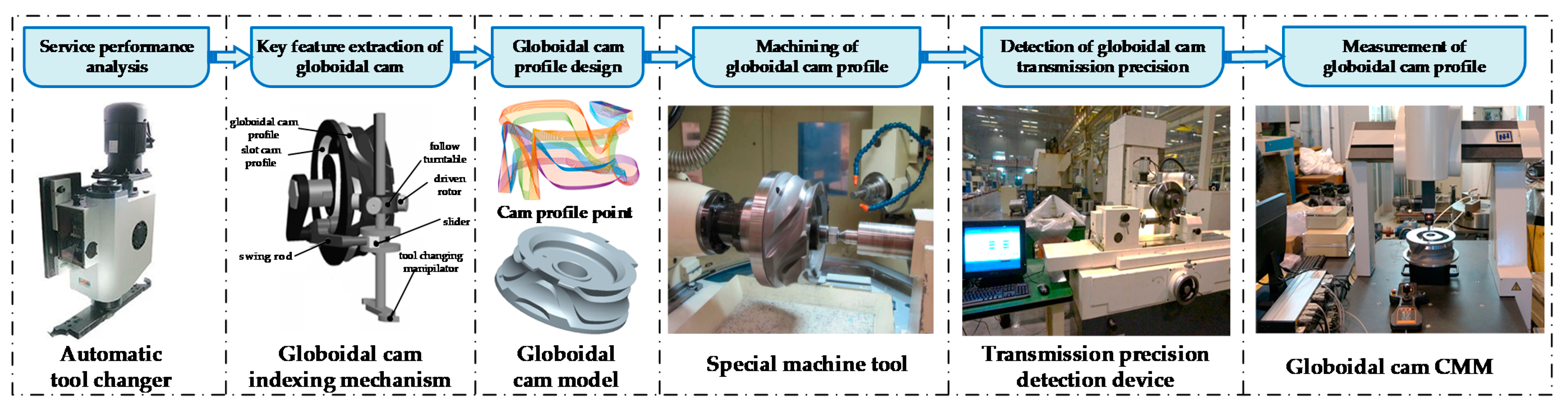
:1. Introduction
2. Analysis Method of Machining Error of Globoidal Cam
2.1. Machining Error Analysis of Globoidal Cam Profile
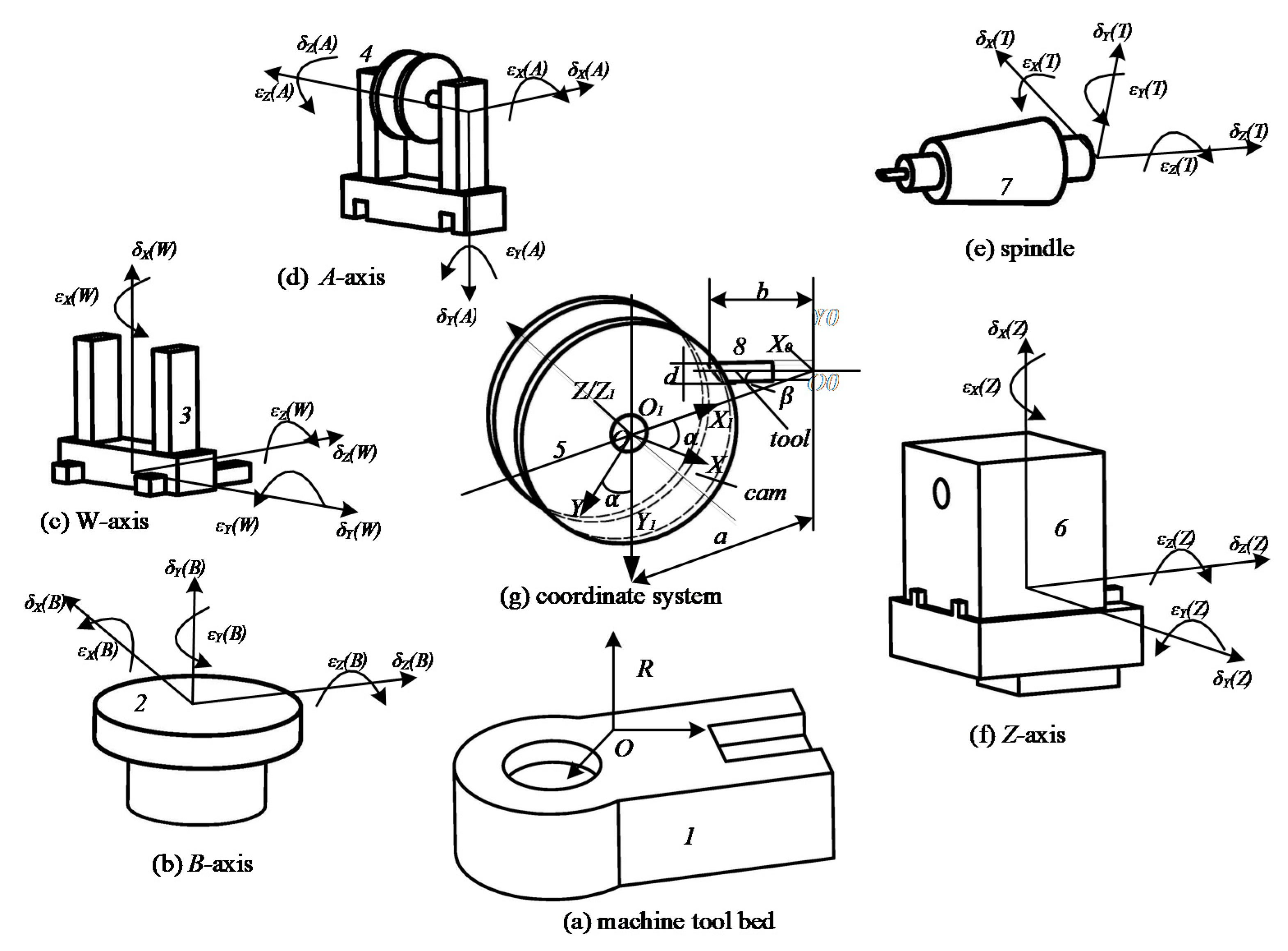
2.2. Multibody System Characteristic Transformation Matrix
2.3. Profile Modeling and Error Sensitivity Analysis of Globoidal Cam
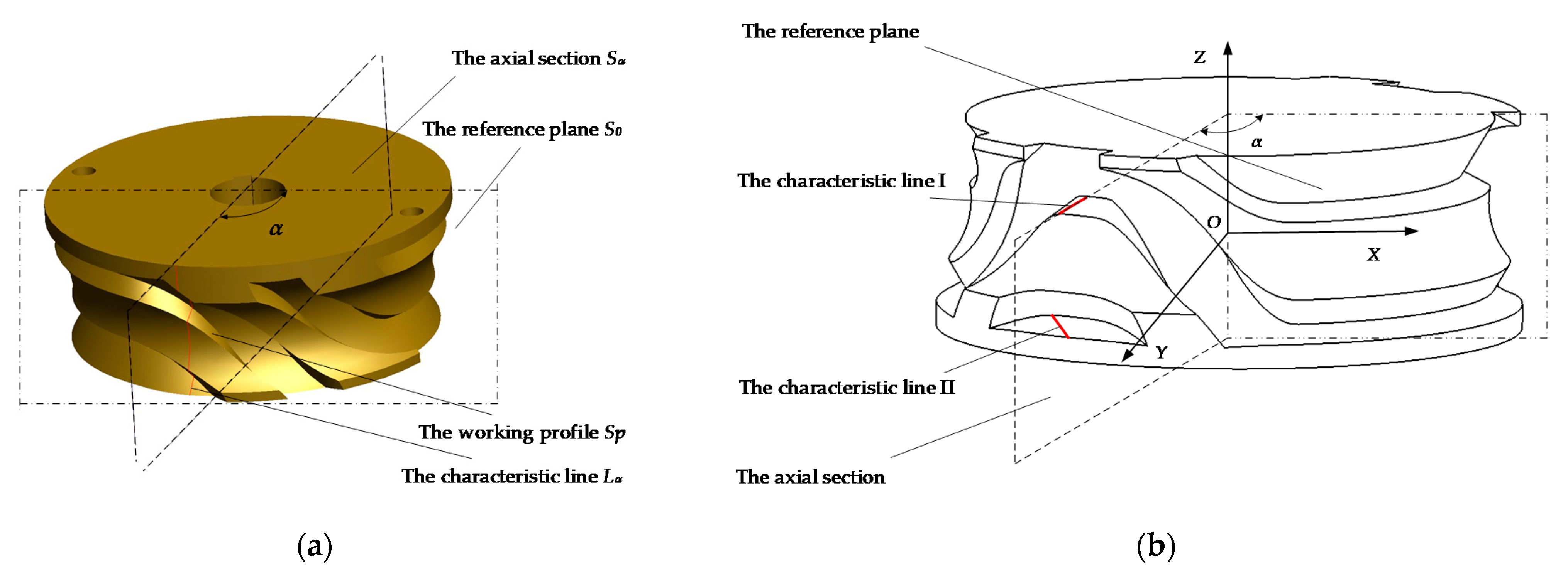
2.3.1. Modeling of Globoidal Cam Profile
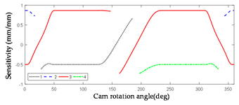
2.3.2. Error Sensitivity Analysis of Globoidal Cam Machining
3. Evaluation and Traceability of Machining Error of Globoidal Cam
3.1. Measurement Method of Machining Error of Globoidal Cam
3.2. Evaluation of Machining Error of Globoidal Cam
- (1)
- Measuring characteristic lines in the dwell segments:
- (a)
- [358°, 2°], four characteristic lines are planned with 1° as a unit;
- (b)
- [52°, 122.5°], 10 characteristic lines are planned with 5° as a unit;
- (c)
- [237.5°, 308°], 10 characteristic lines are planned with 5° as a unit.
- (2)
- Measuring characteristic lines in the indexing segments:
- (a)
- [2°, 52°], 10 characteristic lines are planned with 5° as a unit;
- (b)
- [122.5°, 237.5°], 23 characteristic lines are planned with 5° as a unit;
- (c)
- [308°, 358°], 10 characteristic lines are planned with 5° as a unit.
3.2.1. Error Evaluation of the Characteristic Line of the Dwell Segments
- (a)
- Fit the measurement points to a straight line as the evaluation benchmark;
- (b)
- Solve the coordinates of the endpoints of the theoretical characteristic line;
- (c)
- Find the distance from the two ends of the theoretical characteristic line to the actual characteristic line, and judge whether it is within the tolerance range.
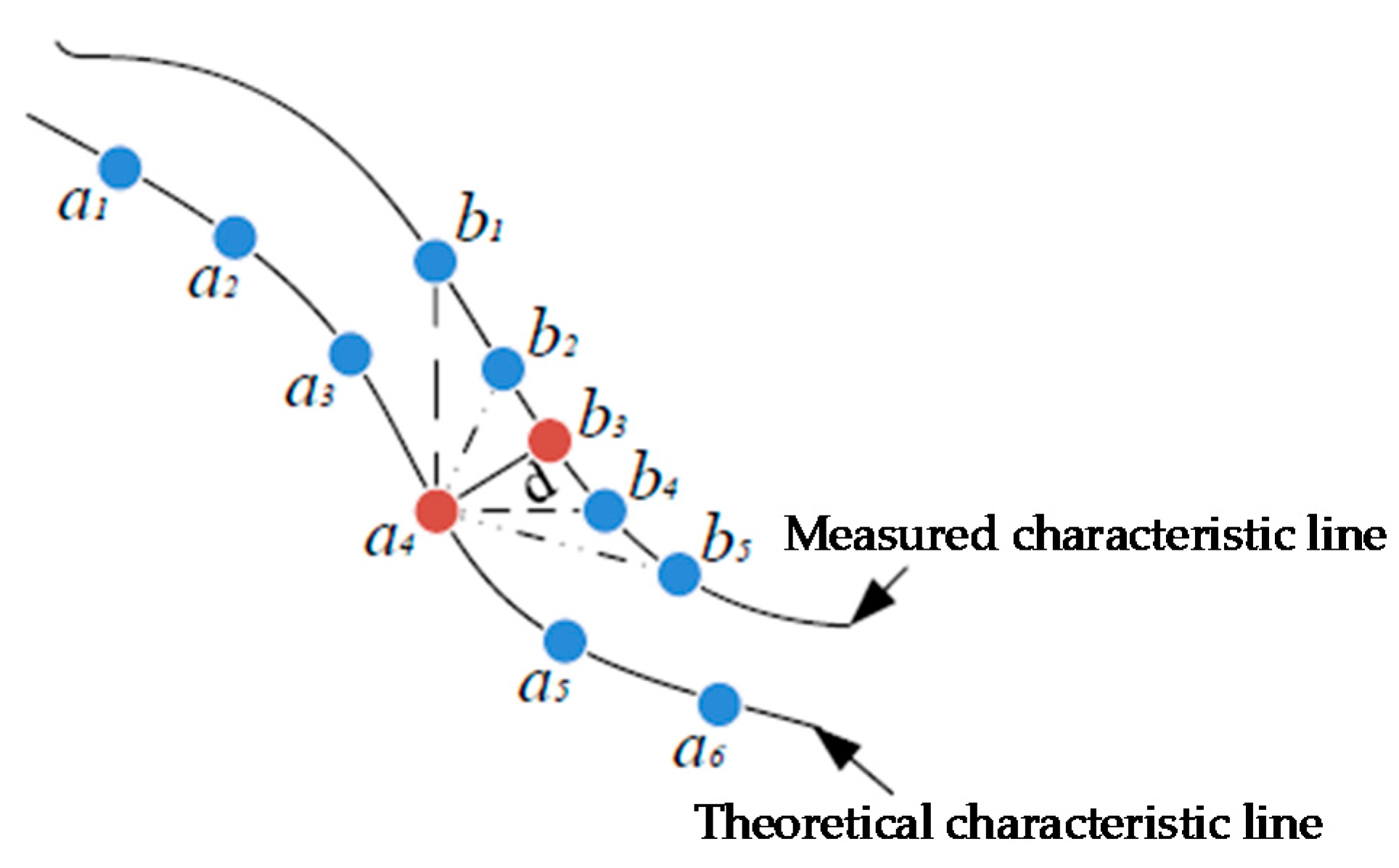
3.2.2. Evaluation of the Error of the Characteristic Line of the Indexing Segments
- (a)
- Use NURBS to fit the actual measurement points into a curve, as the error evaluation benchmark;
- (b)
- Solve the coordinates of the theoretical characteristic points;
- (c)
- Use the segmentation search method to determine the shortest distance from the theoretical characteristic point to the actual characteristic curve, and judge whether it is within the tolerance range.
3.2.3. Evaluation of Surface Profile Error
3.3. Traceability of Machining Errors of Globoidal Cam
- (1)
- Design variables: The design variables of error traceability are all errors of machine tool processing, and the method of segmental traceability is adopted.
- (2)
- Constraints: The constraints of this optimization model need to ensure that the calculation point is located on the globoidal cam profile. The error model of the globoidal cam profile is summarized as in (17).where is the theoretical profile point coordinates (x, y, z) of the globoidal cam with error. α is the cam angle, B is the tool depth, and X is the cam profile error.
- (3)
- Objective function: An objective function based on least squares theory is proposed, as in (19).where n is the number of measurement points., , and are the coordinate values of the points after alignment adjustment, which are called actual coordinate values. When using the sequential quadratic programming method to trace the source of the error, it is finally necessary to obtain a set of error values to maximize the value of the fitness function f(x). At this time, this set of errors is the error traceability result.
4. Experimental Research on Profile Error Detection for Globoidal Cam
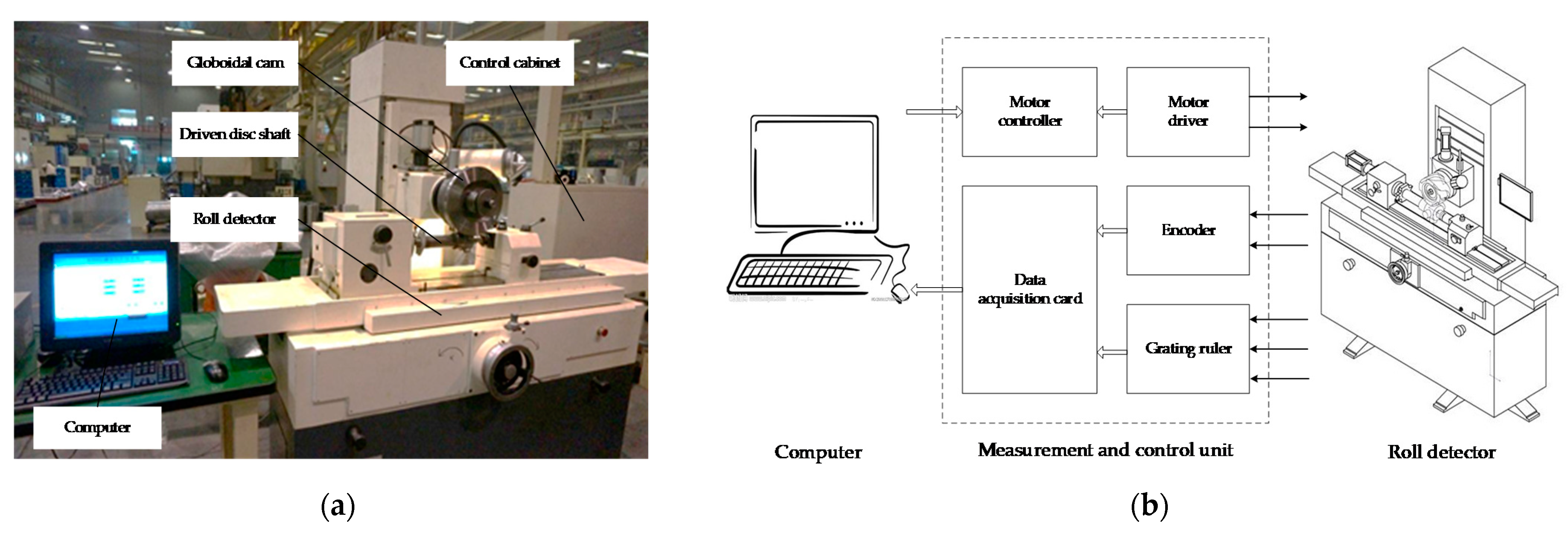
4.1. Testing Experiment of Globoidal Cam Indexing Transmission Accuracy
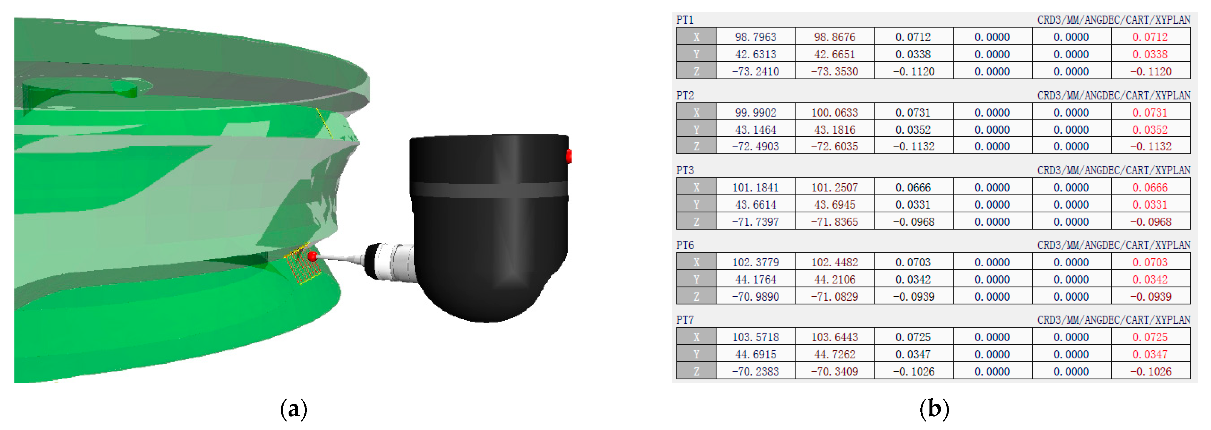
4.2. Measurement Experiment Process
4.3. Error Evaluation for Globoidal Cam
4.3.1. Evaluation of the Error of the Characteristic Line of the Indexing Segment
4.3.2. Evaluation of the Characteristic Line Error of the Dwell Segment
4.4. Error Traceability for Globoidal Cam
- (1)
- Linear displacement error of the main shaft along X direction
- (2)
- Linear displacement error of the main shaft along Y direction
- (3)
- Center distance error
- (4)
- Cam angle error
- (5)
- Follower angle error
- (6)
- Angular displacement error of A axis around X direction
- (7)
- Angular displacement error of A axis around Y direction
- (8)
- B axis angular displacement error around X direction
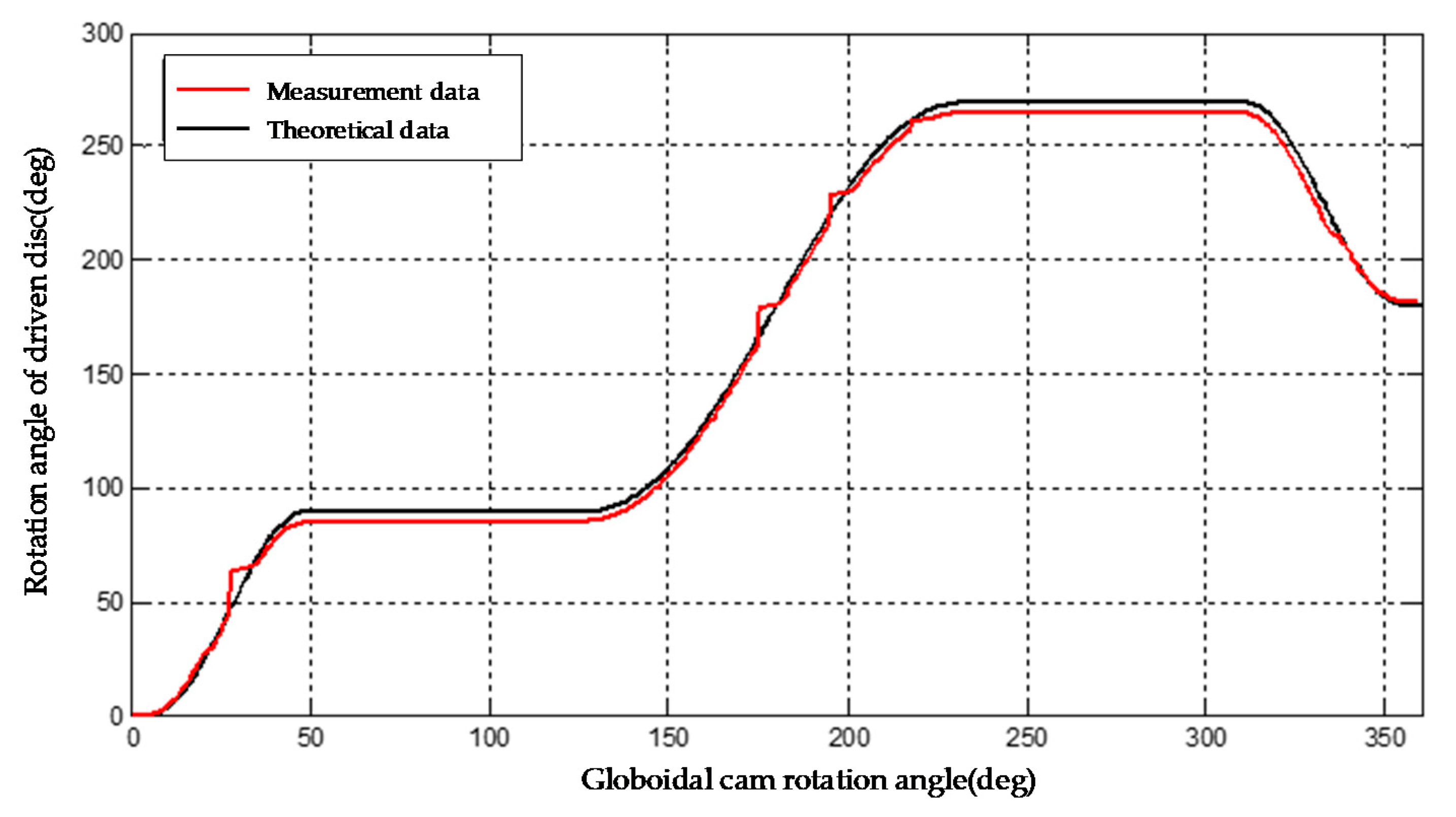
4.5. Testing Experiment of Transmission Accuracy
5. Discussion
6. Conclusions
- (1)
- Based on the multi-body system theory, the special machine tool for globoidal cam machining is analyzed, and the error transfer matrix of globoidal cam machining is deduced. The machining error model of the globoidal cam is established, and a method for comprehensively analyzing the machine tool through the curve of the error sensitivity coefficient of the globoidal cam is proposed. Through the method, the influence law of each error on the globoidal cam profile can be obtained.
- (2)
- By analyzing the characteristics of the globoidal cam profile, a method of segmental measurement and error evaluation of the globoidal cam profile characteristic line and grouping traceability of machining errors is proposed. The dwell segments adopt the two-point method, and the index segments adopt the minimum area method. According to the analysis results of the error sensitivity of the globoidal cam profile, the sequential quadratic programming method is used to trace the processing errors, which improves the data processing speed and the accuracy of the traceability results.
- (3)
- By building a measurement system for globoidal cam transmission accuracy and profile error, the method proposed in this paper is used to evaluate and trace the error of the measurement results, and the machining error compensation of the machine tool is carried out according to the results of error traceability. The experimental results show that the error evaluation and traceability method proposed in this paper can improve the machining accuracy of the globoidal cam.
Author Contributions
Funding
Institutional Review Board Statement
Informed Consent Statement
Data Availability Statement
Acknowledgments
Conflicts of Interest
References
- Ge, Z.H.; Bie, Y.; Jiao, D.; Zhang, T.Y. Study on the profile modification of globoidal indexing cams. Mech. Trans. 2014, 38, 160–162. [Google Scholar]
- Yu, J.W.; Huang, K.F.; Luo, H. Manipulate optimal high-order motion parameters to construct high-speed cam curve with optimized dynamic performance. Appl. Math. Comput. 2020, 371, 1–13. [Google Scholar] [CrossRef]
- Li, Y.L.; Gou, W.D.; Li, J.Y.; Zhou, X.L. Research on the comprehensive performance test specification of chain knife library and manipulator. Mach. Hyd. 2017, 45, 154–159. [Google Scholar]
- Shi, D.F.; Cao, J.J.; Liang, J.S. Design of offset type redundant globoidal cam. Mech. Trans. 2017, 41, 187–190. [Google Scholar]
- Calleja, A.; Fernandez, A.; Rodriguez, A.; De Lacalle, L.N.L.; Lamikiz, A. Turn-milling of blades in turning centres and multitasking machines controlling tool tilt angle. J. Eng. Manuf. 2014, 229 Pt B, 1–13. [Google Scholar] [CrossRef]
- Xia, T.; Xu, L.; Si, J.X. The study of globoidal indexing cam CNC machine tools. Adv. Mat. Res. 2013, 753–755, 888–891. [Google Scholar] [CrossRef]
- Chen, H.; Zhang, Y.M.; Bu, F.H. Parametric design of globoidal indexing CAM. Mach. Des. Manuf. 2007, 6, 3. [Google Scholar]
- Cheng, H.Y. Optimum tolerance for globoidal cam mechanisms. JSME. Int. J. Ser. C 2002, 45, 519–526. [Google Scholar] [CrossRef]
- Yang, S.; Wen, Z.; Li, L. Research on tolerance allocation of globoidal cam mechanism based on improved optimal limit deviation method. Chin. Mech. Eng. 2014, 25, 731–736. [Google Scholar]
- Yin, M.F.; Lyu, C.Y.; Zhao, Z.H. The theoretical study of CAM processing theory and the calculation method of the influence of CAM body deviation error on the profile error are studied. J. Shandong Univer. Technol. 2001, 15, 18–21. [Google Scholar]
- Ji, S.T.; Zhang, Y.M.; Zhao, J. The influence of center distance error of machining center of globoidal cam on convex contour error. J. Beijing Univ. Technol. 2014, 40, 825–830. [Google Scholar]
- Zhang, Y.M.; Ji, S.T.; Zhao, J. Tolerance analysis and allocation of special machine tool for manufacturing globoidal cams. Adv. Manuf. Technol. 2016, 87, 1597–1607. [Google Scholar] [CrossRef]
- Bu, F.H.; Zhang, Y.M.; Shang, D.G. Study on machining error of globoidal cam profile resulting from rotational deviation of location of part in machining. Adv. Mat. Res. 2012, 452–453, 211–218. [Google Scholar]
- Wang, X.F.; Tang, L. Measurement theory and implement of globoidal indexing cam using CMM. J. Tianjin Univ. 2011, 44, 1024–1028. [Google Scholar]
- Lin, P.D.; Hsieh, J.F. Dimension inspection of spatial cams by CNC coordinate measuring machines. J Manuf. Sci. Eng. 2000, 122, 149–157. [Google Scholar] [CrossRef]
- Liang, Y.D.; Song, L.J. Three-dimensional modeling of globoidal indexing cam. Mach. Design Manuf. 2006, 8, 2. [Google Scholar]
- Lin, X.J.; Wang, Z.Q.; Shan, C.W. Method of probe radius compensation for free surface measurement by CMM. Aeronaut. Manuf. Technol. 2011, 10, 75–78. [Google Scholar]
- Wu, P.L.; Hu, D.F. Tool path optimization of globoidal cam flank milling based on spatial linear-regression analysis. J. Adv. Mech. Des. Syst. Manuf. 2019, 13, 60. [Google Scholar] [CrossRef]
- Wu, P.L.; Hu, D.F. Error control of non-equal diameter machining of globoidal cam profile based on adaptive method. J. Braz. Soc. Mech. Sci. 2020, 42, 160–162. [Google Scholar] [CrossRef]
- Abderazek, H.; Yildiz, A.R.; Mirjalili, S. Comparison of recent optimization algorithms for design optimization of a cam-follower mechanism. Int. J. Knowl.-Based Syst. 2019, 11, 1–52. [Google Scholar] [CrossRef]
- Nguyen, T.T.N.; Kurtenbach, S.; Hüsing, M. A general framework for motion design of the follower in cam mechanisms by using non-uniform rational B-spline. Mech. Mach. Theory 2019, 137, 374–385. [Google Scholar] [CrossRef]
- Sateesh, N. Improvement in motion characteristics of cam follower systems using NURBS. Des. Manuf. Technol. 2014, 8, 15–21. [Google Scholar] [CrossRef] [Green Version]
- Xia, B.Z.; Liu, X.C.; Shang, X. Improving cam profile design optimization based on classical splines and dynamic model. J. Cent. South Univer. 2017, 24, 1817–1825. [Google Scholar] [CrossRef]
- Sun, S.W.; Jiang, Z.Q.; Huang, J.; Yang, J.W. Analysis and Detection Method for Machining Error of Globoidal Indexing Cam Profile. In Proceedings of the Asia Conference on Mechanical and Materials Engineering: ACMME, Seoul, Korea, 15–18 June 2018; p. 213. [Google Scholar]


| Error Type | Linear Offset Error | Rotational Error | ||||
|---|---|---|---|---|---|---|
| Error Direction | X | Y | Z | X | Y | Z |
| Spindle | ||||||
| Z-axis | ||||||
| B-axis | ||||||
| W-axis | ||||||
| A-axis | ||||||
| Cam Angle | -- | -- | -- | -- | -- | |
| Turntable Angle | -- | -- | -- | -- | -- | |
| Center Distance | -- | -- | -- | -- | -- | |
| Turntable | ||||||
| Coordinate System | Linear Displacement | Angular Displacement | ||||
|---|---|---|---|---|---|---|
| X | Y | Z | X | Y | Z | |
| Spindle | ||||||
| B-axis | ||||||
| A-axis | ||||||
| W-axis | ||||||
| Z-axis | ||||||
| Cam Angle | -- | -- | -- | -- | -- | |
| Turntable Angle | -- | -- | -- | -- | -- | |
| Center Distance | -- | -- | -- | -- | -- | |
| Symbol | Error Sensitivity Curve | Symbol | Error Sensitivity Curve |
|---|---|---|---|
 |  | ||
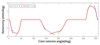 | 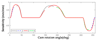 | ||
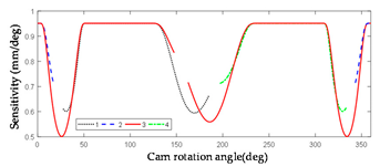 |  |
| Cam Angle Position (o) | Upper Profile Error (mm) | Lower Profile Error (mm) |
|---|---|---|
| 5.1250 | 0.1550 | 0.0350 |
| 10.5125 | 0.1574 | 0.0345 |
| 15.1500 | 0.1456 | 0.0330 |
| 20.0510 | 0.1389 | 0.0294 |
| 25.0650 | 0.1439 | 0.0288 |
| 30.4510 | 0.1530 | 0.0279 |
| 35.1230 | 0.1463 | 0.0253 |
| 40.1380 | 0.1553 | 0.0251 |
| 45.0690 | 0.1491 | 0.0299 |
| 50.1250 | 0.1550 | 0.0289 |
| Cam Angle Position (o) | Upper Profile Error (mm) | Lower Profile Error (mm) |
|---|---|---|
| 60.1250 | 0.1845 | 0.0155 |
| 65.5250 | 0.1745 | 0.0155 |
| 70.0125 | 0.1833 | 0.0149 |
| 75.1125 | 0.1689 | 0.0138 |
| 80.9425 | 0.1762 | 0.0165 |
| 85.2145 | 0.1699 | 0.0165 |
| 90.3468 | 0.1762 | 0.0170 |
| 95.6712 | 0.1789 | 0.0168 |
| 100.4536 | 0.1880 | 0.0160 |
| 105.6921 | 0.1723 | 0.0159 |
| Machining Error | Error Parameter | Traceability Results |
|---|---|---|
| Delta_x | 0.0050 mm | |
| Delta_a | 0.0120 mm | |
| Delta_beta | 0.0056 rad | |
| Delta_Gamma_y | 0.0023 rad | |
| Delta_y | 0.0035 mm | |
| Delta_Alpha | 0.0069 rad | |
| Delta_Gamma_x | 0.0068 rad | |
| Delta_delta_x | 0.0119 rad |
Publisher’s Note: MDPI stays neutral with regard to jurisdictional claims in published maps and institutional affiliations. |
© 2022 by the authors. Licensee MDPI, Basel, Switzerland. This article is an open access article distributed under the terms and conditions of the Creative Commons Attribution (CC BY) license (https://creativecommons.org/licenses/by/4.0/).
Share and Cite
Sun, S.; Qiao, Y.; Gao, Z.; Huang, C. Research on Machining Error Analysis and Traceability Method of Globoidal Indexing Cam Profile. Machines 2022, 10, 219. https://doi.org/10.3390/machines10030219
Sun S, Qiao Y, Gao Z, Huang C. Research on Machining Error Analysis and Traceability Method of Globoidal Indexing Cam Profile. Machines. 2022; 10(3):219. https://doi.org/10.3390/machines10030219
Chicago/Turabian StyleSun, Shuwen, Yunfei Qiao, Zhentao Gao, and Chao Huang. 2022. "Research on Machining Error Analysis and Traceability Method of Globoidal Indexing Cam Profile" Machines 10, no. 3: 219. https://doi.org/10.3390/machines10030219
APA StyleSun, S., Qiao, Y., Gao, Z., & Huang, C. (2022). Research on Machining Error Analysis and Traceability Method of Globoidal Indexing Cam Profile. Machines, 10(3), 219. https://doi.org/10.3390/machines10030219