Article

General Cutting Load Model for Workload Simulation in Spindle Reliability Test

1
Key Laboratory of CNC Equipment Reliability, Ministry of Education, Jilin University, Changchun 130025, China
2
School of Mechanical and Aerospace Engineering, Jilin University, Changchun 130025, China
*
Authors to whom correspondence should be addressed.
Machines 2022, 10(2), 144; https://doi.org/10.3390/machines10020144
Submission received: 24 December 2021 / Revised: 12 February 2022 / Accepted: 14 February 2022 / Published: 16 February 2022

Abstract

:
As the key functional component of the machine tool, the reliability test of the spindle is necessary to verify the reliability of the machine tool. In the reliability test, the cutting load model is the guideline of workload simulation and is the prerequisite to ensure the accuracy and effectiveness of the long-term experiment. However, the existing load models usually aim at the specific cutting force at the tool-tip, thereby ignoring the versatility, maneuverability, and accuracy of the load model when applied in the spindle reliability test. In this study, a general cutting load model for the machine tool spindle is established in a form of radial-axial-torque decomposition, and the radial force is simplified as non-rotating status for the maneuverability of conducting a load simulation. The difference between rotating and non-rotating radial force on the reliability calculation is also discussed and corrected using bearing fatigue analysis. A spindle reliability test platform with radial force, axial force, and torque simulation is developed according to the cutting load model, while the loading spectrum is compiled for conducting the spindle reliability test. This research is of great engineering value for the designing of the spindle reliability test.

1. Introduction

As the key functional component of CNC machine tools, the reliability level of the spindle directly determines the operating rate of machine tools [1]. The spindle reliability test is an effective means to stimulate the potential faults and evaluate the reliability by applying reasonable environmental and working condition stress [2]. As such, it is important to design a suitable test platform together with reasonable experimental plans to carry out the spindle reliability test.
The spindle cutting load model is the basis of load simulation in spindle reliability tests. The accurate reduction of the cutting load condition of the spindle is crucial to ensure the accuracy and effectiveness of the spindle reliability test. The existing modeling methods of cutting load are mainly divided into the following four categories: (1) the analytical modeling method, (2) numerical method based on physical models, (3) semi-empirical modeling method based on experiments, and (4) semi-analytical method based on mechanistic models [3]. Many scholars have established the cutting load models of milling [4], drilling [5], and boring [6] based on the aforementioned methods to predict the cutting load. The first kind of method is mainly based on the shear plane or shear deformation zone theory of orthogonal cutting, and the cutting force models of oblique edge cutting and practical three-dimensional milling are obtained through appropriate transformation [7]. The second method establishes a set of partial differential equations and the corresponding boundary and initial conditions describing the mechanical–thermal coupling of the machining process and then solves the equations by numerical algorithms, such as finite element, boundary element, or finite difference method [8]. The third method is usually based on the experimental data under different process parameters to establish the nonlinear exponential function relationship between cutting force and process parameters [9]. The fourth method requires experiments to calibrate the coefficients in the model for different tool-workpiece combinations [10]. However, the above models only demonstrate the cutting load model for a specific machining method, and the solving process of each machining process is complex due to enormous known parameters. Thus, these existing models can hardly guide the spindle reliability test directly. In this case, the application of a simple and general load model to the reliability loading test is urgently needed.
The cutting load involved in the establishment of the spindle load model is remarkably complex mainly due to the shear stress, friction, and process damping between the removed material and the cutting edges surface [11,12]. To explore a general method to describe the interaction between different materials in the machine process, Kaymakciet et al. proposed a unified geometric model of milling, turning, drilling, and boring operations. The force is further transformed into the XYZ coordinate system of milling, turning, drilling, and boring by assigning specific parameters [12]. Altintas and Kilic extended the model to include cutting vibration in dynamic cutting loads. Their model can predict the flutter stability of multiple machining methods with specific cutting edges [13]. Kilic considered the influence of relative vibration between cutting edge and workpiece segment and constructed a dynamic cutting load model, including shear, static plowing, and process damping components [14]. However, the cutting load models still exist following shortcomings. (1) Complex geometric shapes and tool parameters should be considered, thus complicating their application in engineering. (2) The existing load model mainly focuses on the load on the cutting edge and workpiece, which cannot completely reflect the effect of load on the spindle. (3) Most of the existing load models are devoted to the accurate simulation of a single machining process and cannot represent all machining processes. Therefore, exploring a cutting load model, which considers the theoretical basis and the versatility of the model, is necessary for conducting the spindle reliability test.
The spindle reliability test can be performed by using the cutting load model, and many scholars have established the spindle reliability test platform. For example, Guo designed a 6-DOF parallel loading mechanism to realize the reliability test of the miniature spindle. However, the load simulation frequency is considerably lower than that of the actual cutting load [15]. Ding proposed an improved sliding mode dynamic matrix control strategy to ensure the force tracking performance and improve workload simulation accuracy [16]. Chen proposed a load-dependent precision evaluation method based on a workload simulation platform, which ensures the measurement accuracy under the spindle reliability test [17]. However, the loading mode adopted by the above test system does not consider the rotational character of radial cutting force but directly removes the rotational character, which alters the actual loading frequency and makes the reliability result incorrect. Therefore, a concise and general cutting load model is proposed in accordance with the existing cutting theory and the characteristics of various machining operations. This model can be used to guide the load simulation of the spindle reliability test platform and can provide a good theoretical basis for engineering applications.
A general cutting load model in the spindle reliability test is proposed in this paper. First, a general load model in radial-axial-torque (RAT) form, which can describe the operations of milling, drilling, and boring, is established by the load micro-element model. Second, the general cutting load model is corrected by analyzing the different effects of the rotating and the non-rotating radial forces on the cumulative fatigue times of the spindle bearing, and the cutting load model is verified by cutting tests. Finally, a spindle reliability test system with the combined application of radial force, axial force, and torque is developed, and the loading spectrum is compiled to guide the spindle reliability test.

2. Establishment of Cutting Load Model Based on Rat Decomposition

The load on the spindle is divided into radial force, axial force, and torque (RAT) to facilitate the analysis of the load on the spindle. The load condition of the spindle depends on many factors, such as cutting operations, process parameters, and tool-workpiece materials. Accurately solving the load conditions determined by these complex variables is difficult. Therefore, a general cutting load model is established by analyzing the basic pattern of cutting load exerted on the spindle load under different processing conditions. This model provides a sufficient theoretical basis for guiding spindle load simulation.

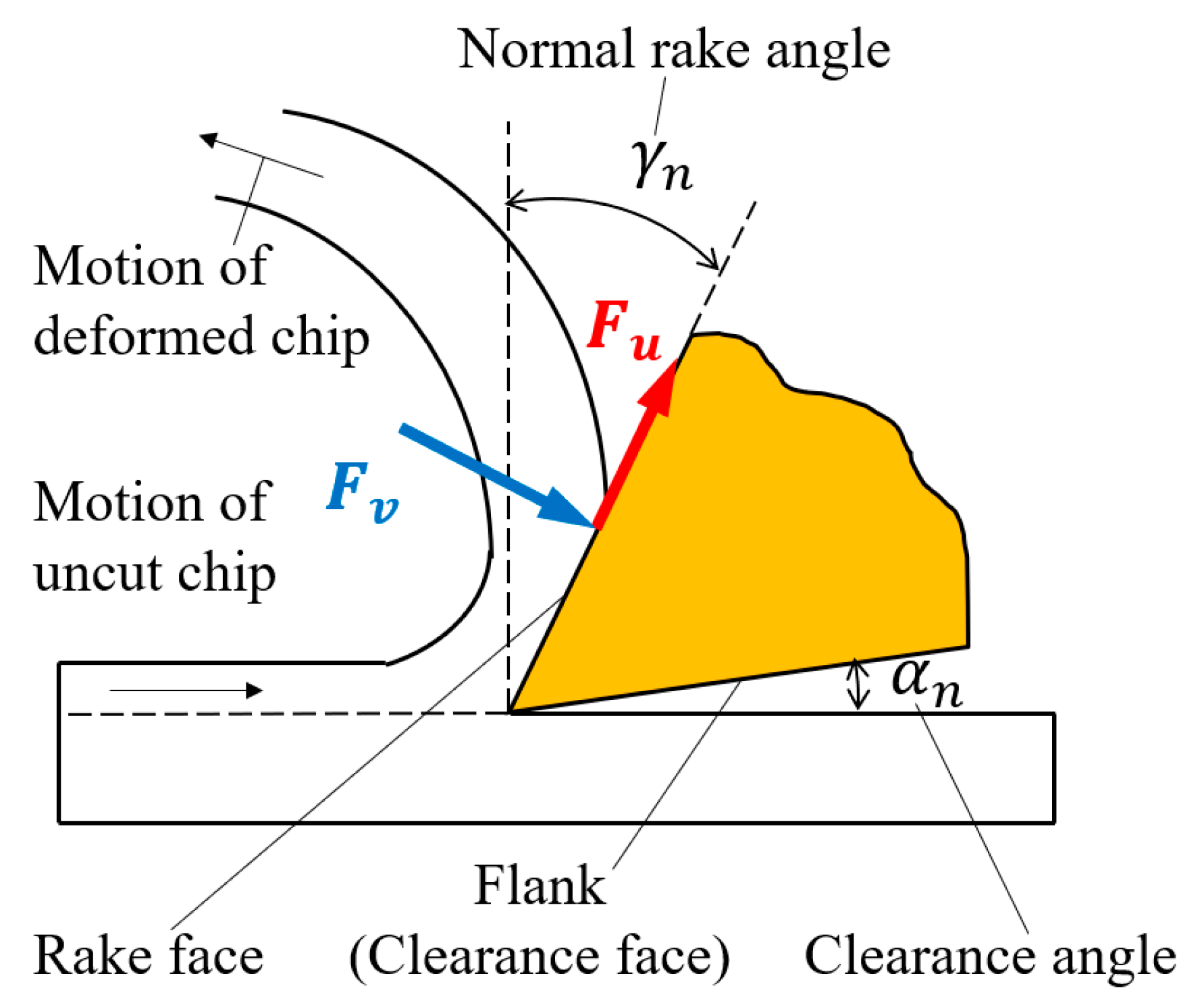
2.1. Establishment of Micro-Element Model

The machining center mainly performs milling, drilling, and boring. Therefore, the development of the micro-element load model is the basis of establishing the general cutting load model. Milling cutters, drills, and boring cutters installed on the spindle are uniformly distributed with one or more inserts during operation. The tool cutting load is the integral of each segment load along the edge. Figure 1 shows that the cutting load comes from both the normal force F v caused by the workpiece resisting the action of the cutting insert and the friction force F u between the removed material and the rake face.
Classical cutting theory indicates that the friction force d F u j and normal force d F v j of the i th segment in the j th insert can be expressed as [18]:
{ d F u j d F v j } i = { K u c j ( i ) d A c j ( i ) + K u e j d S j ( i ) K v c j ( i ) d A c j ( i ) + K v e j d S j ( i ) }
where the element normal force d F v and the element friction force d F u are functions of differential uncut chip area ( d A c ) and differential chip width ( d S ), respectively. K v c j and K u c j are the friction and normal cutting force coefficients, respectively. K u e j and K v e j are the edge force coefficients in oblique cutting for each insert ( j ) and differential segment ( i ), respectively.
The geometric relationship of the segment for milling, drilling, and boring is shown in Figure 2.
In Figure 2, a p is the depth of cut, D is the cutter diameter, R is the radius of boring cutter, κ r i is the cutting edge angle of the insert, d z is the constant axial thickness of each cutting edge element, and h j ( i ) is the uncut chip thickness.
d S j ( i ) = d z / s i n κ r i
The differential uncut chip area ( d A c ( i ) ) is the product of uncut chip thickness ( h j ( i ) ) and differential chip width ( d S j ( i ) ).
d A c j ( i ) = h j ( i ) × d S j ( i ) = h j ( i ) × d z / s i n κ r i
The micro-element load of the i th segment of the j th insert in chip flow (U,V) coordinates ( d F u j , d F v j ) can then be expressed as:
F i j U V = { d F u j d F v j } i = ( { K u c j ( i ) K v c j ( i ) } h j ( i ) + { K u e j ( i ) K v e j ( i ) } ) d z / s i n κ r i
The micro-element loads of milling, drilling, and boring are the same. Therefore, a unified micro-element load model can be established, thus laying a theoretical foundation for analyzing the cutting load pattern.

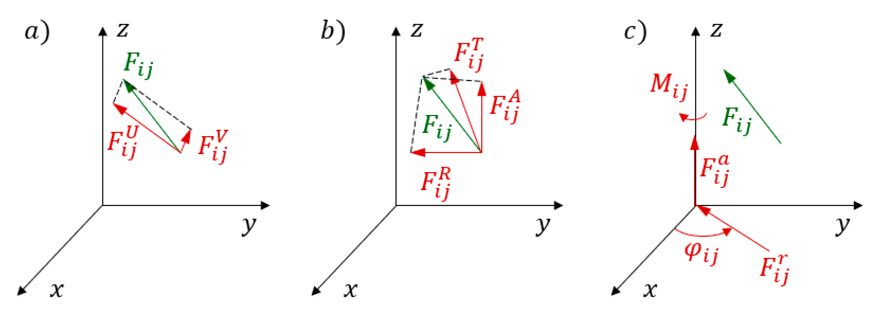
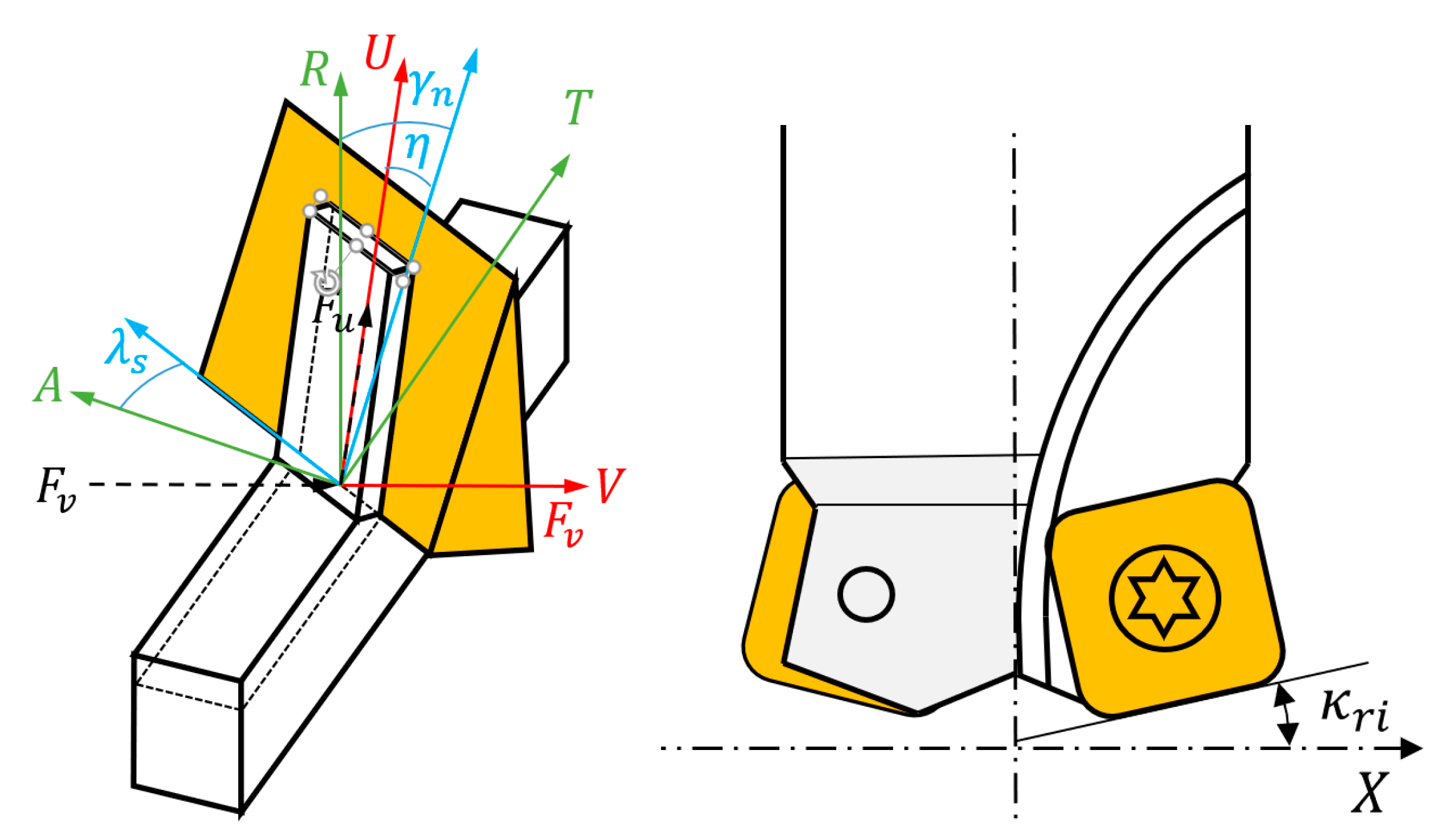
2.2. Establishment of Micro-Element Load Model under RAT Decomposition

Decomposing the load on the tool’s cutting edge into the RAT coordinate system is necessary to establish the general cutting load model in the spindle reference coordinate (RAT coordinate). The micro-element load ( F i j U V ) of the segment ( i ) in the insert ( j ) in the chip flow (U,V) coordinates (Figure 3a) is the spatial force, which can be converted into the insert reference (RAT) coordinates by coordinate transformation to describe the cutting force direction quantitatively (Figure 3b). The tangential force ( F i j T ) in the insert reference coordinates is moved to the spindle axis and combined with the original radial force ( F i j R ) to generate a new radial resultant force ( F i j r ), and an equivalent torque ( M i j ) is generated in the spindle reference (RAT) coordinate (Figure 3c). Therefore, the RAT decomposition form of cutting load is constructed in this paper.
The specific conversion process is as follows.
Firstly, the load is transformed from the chip flow (U,V) coordinates to the Radial-Tangential-Axial (RTA) coordinates of the tool. The conversion process consists of three steps.
Step 1, the load is projected to the cutting edge.
{ F X F Y F Z } e d g e = [ 0 1 sin η 0 cos η 0 ] { F u F v }
where η is the chip flow angle, see Figure 4.
Step 2, the load is transformed from the cutting edge to tool reference coordinates (XRYRZR) according to the geometry and location of the tool as in Figure 4:
{ F X F Y F Z } T o o l = [ cos ( κ r i + p π 2 ) 0 sin ( κ r i + p π 2 ) 0 1 0 sin ( κ r i + p π 2 ) 0 cos ( κ r i + p π 2 ) ] [ 0 0 1 cos λ s sin λ s 0 sin λ s cos λ s 0 ] [ cos γ n 0 sin γ n 0 1 0 sin γ n 0 cos γ n ] { F X F Y F Z } e d g e = ( T T U ) 3 × 3 { F X F Y F Z } e d g e
where γ n is the normal rake angle, λ s is the inclination (helix) angle, κ r i is the cutting edge angle of the insert, p is the parameter to include type of operation, and T T U is the matrices used in force transformations.
Step 3, the cutting forces in insert reference coordinates are transformed from the tool reference insert to operation-specific machine coordinates (radial-tangential-axial (RTA)) as follows:
{ r t a } R = [ 1 0 0 0 D c j 2 0 0 0 1 ] { F X F Y F Z } T o o l = [ 1 0 0 0 D c j 2 0 0 0 1 ] ( T T U ) 3 × 3 { F X F Y F Z } e d g e = [ 1 0 0 0 D c j 2 0 0 0 1 ] ( T T U ) 3 × 3 [ 0 1 sin η 0 cos η 0 ] { F u F v } = ( T R U ) 3 × 2 { F u F v }
Through the above process, the micro-element load can be transformed into the insert reference coordinates (radial-tangential-axial (RTA)) by a geometry matrix T R U after determining the operation and tool. The expression of micro-element cutting load in the RTA coordinate is as follows:
{ d F r i j d F t i j d F a i j } = ( T R U ) 3 × 2 { d F u i j d F v i j } . g i j = [ a 11 a 12 a 21 a 22 a 31 a 32 ] { d F u i j d F v i j } . g i j
where d F r i j , d F t i j , and d F a i j are the radial, tangential, and axial forces on the i th segment of the j th insert, respectively. a i j is the parameters related to tool geometry. When the geometry, material and cutting plan is determined, these parameters are also determined. g i j ( φ i j ) is used to determine whether the segment is in cutting state. Milling is usually in an intermittent machining state: g i j ( φ i j ) = 1 when the segment ( i ) in the insert ( j ) is in cutting state; otherwise, g i j ( φ i j ) = 0 . Drilling and boring belongs to continuous machining, and all micro-elements z i j of the insert participate in cutting at any time, that is, g i j ( φ i j ) = 1 .
The tangential force d F t i j in Equation (8) is moved to the rotating cutter axis. The radial force d F r i j and the tangential force d F t i j are then combined into a radial resultant force (principal cutting force), and the torque load is supplemented. Thus, the load element can be converted to a load relative to the spindle in the RTA coordinates.
{ d F R i j d F A i j d F M i j } = [ a 11 + a 21 a 12 + a 22 a 31 a 32 a 31 . R c a 32 . R c ] { d F u i j d F v i j } . g i j
where R c is the radial distance of the insert from the rotating cutter axis.
The expression of d F u j , d F v j , and h j ( i ) , d z is given in Equation (4). Binding Equation (9), the general cutting load micro-element model d F i j of the RAT of the spindle can be expressed as:
d F i j = { d F r i j d F a i j d M i j } = [ a 11 + a 21 a 12 + a 22 a 31 a 32 a 31 . R c a 32 . R c ] ( { K u c i j K v c i j } h j ( i ) + { K u e i j K v e i j } ) g i j d z / s i n κ r i
The coefficients related to the tool geometric parameters are simplified to a r , a a , a M , b r , b a , and b M . The above equation can be simplified as follows:
d F i j = { d F r i j d F a i j d M i j } = ( [ a r a a a M ] h i j + [ b r b a b M ] ) g i j d z
Overall, the RAT decomposition form can be established after the cutting load is transformed from the cutting edge (U,V) coordinate to the spindle reference (RAT) coordinate. It is noted that the uncut chip thickness ( h i j ) is the key to solving the micro-element load model in the RAT coordinate.

2.3. Establishment of the General Cutting Load Model of Spindle

Combining the load condition characteristics of the spindle in different operations with the micro-element load model in RAT coordinates, the general cutting load model of the spindle under different machining modes is established by solving the total cutting load of the spindle through the uncut chip thickness expressions of milling, drilling, and boring.
The uncut chip thickness expressions of milling, drilling, and boring are established by the load condition characteristics of different machining processes, and the uncut chip thickness expressions are substituted into the micro-element load model (Equation (11)) in RAT coordinate. The general cutting load model of spindles with different operations is analyzed and established.

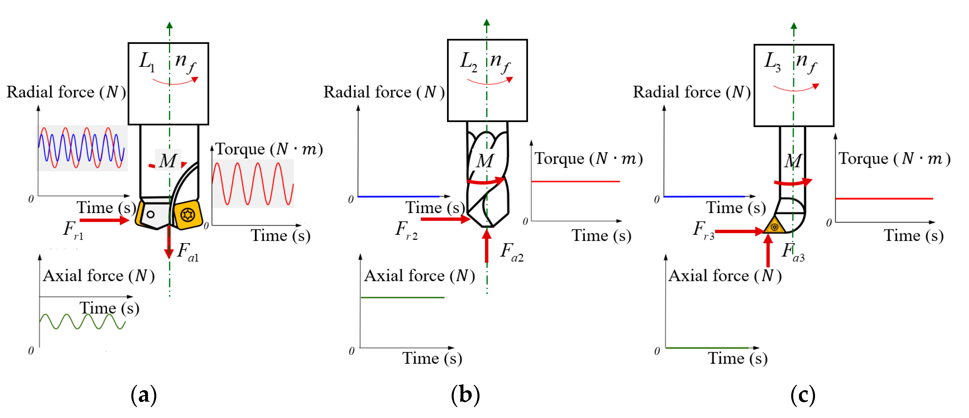
2.3.1. Cutting Load Model under Milling Operation

The milling process is intermittent. The milling dynamic uncut chip thickness model established by Lamikiz et al. [19] revealed that the uncut chip thickness ( h i j ) in the micro-element model of cutting load is approximately the sine function of the orientation angle of the insert ( φ ). If the spindle rotates clockwise during milling, then the uncut chip thickness ( h i j ) is expressed as [20]:
h j ( i ) = v f N n s i n κ r i s i n φ i j ( z )
where n is the speed of the rotating tool, N is the number of inserts of the milling cutter, and v f is the cutting velocity vector represented in design and reference frame.
The expression of uncut chip thickness in milling (Equation (12)) is substituted into the micro-element load model (Equation (11)) in the RAT coordinate system.
d L i j = { d F r j d F a j d M j } i = ( [ a r a a a M ] v f N n s i n ( φ j ) + [ b r b a b M ] ) g i j d z
The cutting load expression of the single insert of the spindle can be obtained by integrating the micro-element load model in milling with the tool geometry.
F j = { F r F a M } j = [ b 11 b 12 b 13 ] v f N n s i n ( φ j ) + [ b 21 b 22 b 23 ]
The entire milling process is equivalent to the repeated motion of an insert in the time domain. Therefore, the milling force of any insert can be obtained by translating a certain angle 2 π / N of a specific insert cutting force in the time domain:
F j ( φ ) = F j 1 ( φ 2 π N )
The total milling force L 1 ( φ ) can be obtained as shown below by summing the milling forces of all inserts.
L 1 ( φ ) = i = 1 N F j ( φ ) = i = 1 N F j ( φ ( i 1 ) 2 π N )
The Fourier series expression of the total milling force after the Fourier transform of total milling force (Equation (16)) is presented as follows:
L 1 ( φ ) = n   =   F ( n ) e j n φ
The load on the spindle in the milling process includes the constant component, N times frequency component, 2N times frequency component, 3N times frequency component, and other dynamic frequency components. The cutting load model of the spindle under the milling mode in the RAT coordinate is as follows:
L 1 = [ B r + n = 1 p A r n sin ( n N ω t + θ r n ) B a + n = 1 p A a n sin ( n N ω t + θ a n ) B M + n = 1 p A M n sin ( n N ω t + θ M n ) ]
It can be seen from the above formula that B r , B a , and B M are the static components of the milling load; A r n , A a n , and A M n are the dynamic components of n times spindle rotation frequency; θ r n , θ a n , and θ M n are the phase angles.

2.3.2. Cutting Load Model under Drilling Operation

Theoretically, the two inserts of the bit are centrally symmetrical, the radial cutting forces of the inserts cancel each other, and the radial resultant force is zero. However, the radial runout is produced during drilling results in different inserts with various cutting thicknesses due to the generally slender shape of the bit. The direction of the radial runout ( ρ r ) and its angle with the insert ( η ) are shown in Figure 5.
In Figure 5, ρ r is the radial runout of the axis, η is the angle between the runout direction and the insert, and Δ h r is the change in uncut chip thickness caused by radial runout.
The runout component produced by the radial runout ρ r on the j th insert along the radial direction (cutting thickness direction) is ρ r cos η , and the runout component along the direction perpendicular to the insert is ρ r sin η . Only the runout along the insert direction has a significant effect on the uncut chip thickness. Figure 5 shows that the change in the uncut chip thickness is Δ h r = ρ r cos η c o s κ r , and the uncut chip thickness after considering the runout is as follows:
h j = v f N n f s i n κ r + Δ h r = v f N n f s i n κ r + ρ r cos η c o s κ r
The micro-element load model in drilling is obtained by substituting Equation (19) into the micro-element load model in the RAT coordinate system (Equation (11)).
d L i j = { d F r j d F a j d M j } i = ( [ a r a a a M ] ( v f N n s i n κ r + ρ r cos η c o s κ r ) + [ b r b a b M ] ) d z
The cutting load model under the drilling operation is established as shown below by integrating the micro-element load model of the bit and summing all the inserts.
L 2 = { F r F a M } = { B r B a B M }
If the radial runout of the bit is zero, or the direction of the runout is perpendicular to the angle of the bit, then the resultant force of the radial force is zero. In this case, the axial force and torque, respectively, contain only the static components B a and B M .

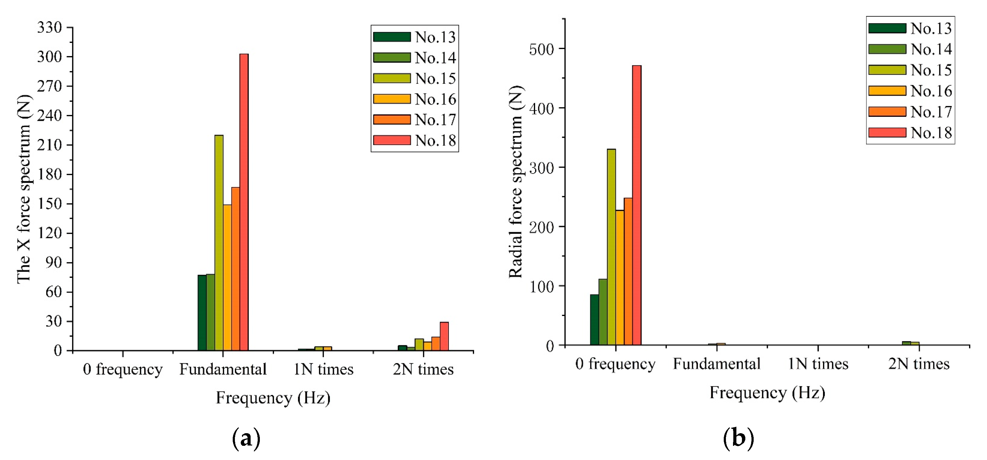
2.3.3. Cutting Load Model under Boring Operation

Boring is generally precision or semi-precision machining, and its cutting force is mainly along the circumferential tangent direction of the insert tip trajectory. Taking the typical single point boring cutter as an example, the uncut chip thickness is as follows:
h j = v f n f
Equation (22) can be substituted into the micro-element load model in the RAT coordinate system (Equation (11)), and the integral solution can be conducted to obtain the cutting load model in the boring operation, such as Equation (23). Radial force, axial force, and torque, respectively, contain only static components B r , B a , and B M .
L 3 = { F r F a M } = { B r B a B M }
Milling, drilling, and boring operations are closely related in accordance with Equations (18), (21) and (23), respectively. Therefore, the three cutting load models are unified into a general cutting load model to facilitate the application of reliability engineering. L m is used in this paper to represent the general cutting load model under all kinds of machining processes, and the following m distinguishes different machining processes.
  • Milling: m = 1
  • Drilling: m = 2
  • Single point boring: m = 3
The general cutting load model of milling, drilling, and boring can be established by setting the factor of the machining process δ m ( δ m = int [ ( 3 m ) / 2 ] ).
L m = { F r F a M } m = { A r δ m n = 1 p sin ( ω N t + θ r ) + B r A a δ m n = 1 p sin ( ω N t + θ a ) + B a A M δ m n = 1 p sin ( ω N t + θ M ) + B M }
The basic law in different machining processes is shown in Figure 6.
Figure 6 shows that the cutting load pattern in different machining processes L m includes the basic rotational speed n , radial force F r , axial force F a , and torque M . The milling load is complex (in Figure 6a), and axial and radial forces have static ( B r , B a , B M ) and dynamic ( n = 1 p A h n sin ( n N ω t + θ r n ) components. Drilling contains only static load components ( B r , B a , B M ) (Figure 6b), and only static load components ( B r , B a , B M ) are included in boring (Figure 6c). Therefore, determining the static and dynamic component ranges of cutting load according to typical working conditions and conducting simulated loading tests is necessary during the simulation of spindle working conditions.

3. Correction and Verification of General Cutting Load Model of the Spindle

The radial force is rotating because of spindle rotation in the machining process. However, applying rotating force on the spindle is extremely difficult in engineering. As such, the radial force in the general cutting load model is simplified as a non-rotational force. The life of the bearing is not only related to the load amplitude, but also to the loading frequency. To eliminate the rotational character of radial force in the load model, the relative relationship of fatigue cumulative times of the bearing between the rotational and non-rotational radial force should be deduced on the basis of the bearing fatigue life analysis.

3.1. Correction of General Cutting Load Model for Spindle

The measurements of the spindle load, the load in the spindle reliability test, and the cutting load solved by the traditional load model are all in the non-rotating state, which is inconsistent with the actual rotational load on the spindle. Therefore, the conversion relationship between the non-rotating load in the traditional model and the rotational load in the revised model is established in accordance with the rotation influence of the radial force on the spindle fatigue. According to the schematic of loading of the spindle parts (Figure 7), in the process of spindle rotation, the rotational speeds of the ball, inner raceway, and outer raceway of the bearing are different, so it is necessary to analyze the fatigue life for different spindle parts, respectively.

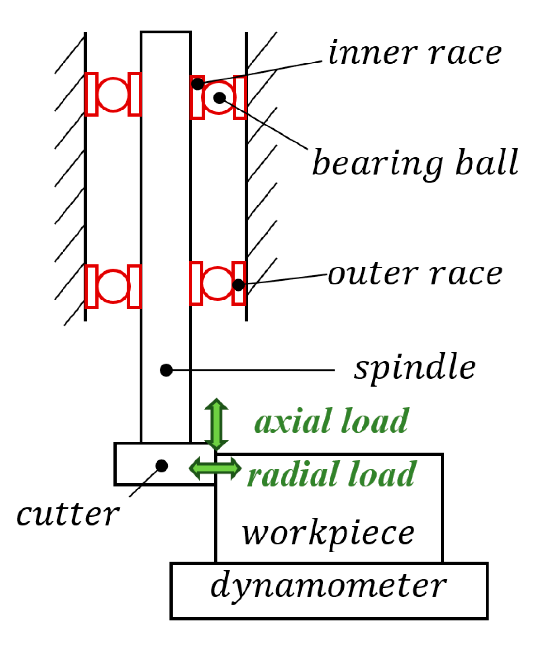
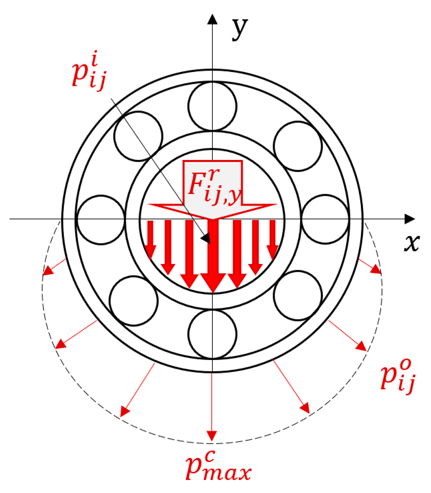
3.1.1. Fatigue Life Analysis of Spindle Bearing

Fatigue cumulative damage theory indicates that stress amplitude and cycle times affect fatigue life. Thus, it is necessary to calculate the frequency of the load on each spindle part.
The rotating shaft, the bearing inner race, and the bearing ball move at high speeds around the rotary axis during the spindle operation while the direction of radial force changes continuously in machining. The distributed loads on the bearing ball are illustrated shown in Figure 8.
Figure 8 shows that p i j i is the stress caused by the contact between the bearing inner race and the bearing ball, p i j o is the stress caused by the contact between the bearing outer race and the ball, and p max c is the maximum contact stress.
From the viewpoint of bearing fatigue life, fatigue crack is the main cause of bearing failure. According to the Paris equation of material fracture mechanics, the equation of contact failure is [20]:
N b = b 1 c 2 β 0 p max c
where N b is the fatigue life of bearings, b is the contact ellipse short axis, β 0 and c are the material parameters related to the crack growth rate.
Therefore, Equation (26) shows that the load related to the fatigue life of the bearing is only the maximum contact stress ( p max c ), and the direction of the load has no effect on the fatigue life. During the working process of the spindle, the axial contact stress of all parts in the bearing is of the same frequency, while the radial load will lead to different contact stress frequency at the same time due to the different rotational speeds of the ball, inner ring and outer ring of the bearing. Therefore, the total time to achieve fatigue life is different, and the load model needs to be corrected.

3.1.2. Correction of the Cutting Load Model

The reasons for the Correction of the model mainly include two aspects. On the one hand, the radial load is rotating (in the RAM coordinate system), but only the load in the fixed direction in the machine tool coordinate system can be applied in the test; On the other hand, the total time for the radial load to reach the fatigue life is different because of the different rotational speeds of the ball, inner ring and outer ring of the bearing, which needs to be analyzed and discussed separately. Finally, a general cutting load model is established, which can be used in engineering practice.
The geometric relationship between the rotational speed of the ball and the angular speed of the spindle is shown in Figure 9a. The calculation process of the linear speed of the bearing inner race ( v 0 ) and the centerline speed of the ball ( v b ) is, respectively, shown in Equations (26) and (27).
v 0 = ω d a 2 = ω b D b
v b = ω b D b 2 = ω s d a + D b 2
where d a is the diameter of the bearing inner race, ω is the angular speed of the spindle, ω b is the rotational speed of the ball, r b is the diameter of the ball, and ω s is the common angular speed of the ball.
Combining Equations (26) and (27), the relationship between the common rotational speed of the ball and that of the spindle is as follows:
ω s = d a 2 ( d a + D b ) ω
A non-rotating radial force is loaded in the machine tool coordinates (Figure 9a). Equation (28) indicates that the frequency of non-rotating radial loading ( f 1 ) is required as shown below when the bearing ball reaches the fatigue life N b considering the load frequency f b and the loading time N b .
f 1 = 2 ( d a + D b ) d a f b
The rotation radial force is loaded in the RAT coordinate (Figure 9b), and the loading frequency is f b . The frequency of rotation radial loading ( f 2 ) is required as follows when the bearing ball reaches the fatigue life N b considering load frequency f b and loading time N b .
f 2 = 2 D b + d a D b f b
Considering the bearing ball, when the ball reaches the same fatigue life ( N b ), the relationship between the loading frequency f 11 under the non-rotating directional load (machine tool coordinates) and the loading frequency f 2 under the rotating directional load (in RAT coordinate system) is:
f 11 = 2 D b ( d a + D b ) d a ( 2 D b + d a ) f 2
With the same calculation method, the relationship between the loading frequency of the ball, inner ring and outer ring of the bearing and spindle under non-rotating directional load (machine tool coordinates) and the loading frequency of radial load as rotational load (in RAM coordinate system) is obtained as follows:
f 12 = f 2
f 13 = n f 60 f 2
Let ρ 1 = 2 D b ( d a + D b ) d a ( 2 D b + d a ) , ρ 2 = 1 , ρ 3 = n f 60 , the equivalent loading frequency of different parts of the spindle is related to ρ M ( M = 1 ,   2 ,   3 ).
The corrected general cutting load model is suitable for load simulation under different spindle operations (by selecting different coefficients m), and the corresponding corrected model L M m is selected in accordance with the actual common damage form of the bearing (damage form parameter M ). Selecting the corresponding corrected model L M m , the corrected general cutting load model under the milling, drilling, and boring operations can be established.
L M m = { F R F A M } M m = { B r + δ m n = 1 p A r n sin ( ρ M n N ω t + θ r n ) B a + δ m n = 1 p A a n sin ( n N ω t + θ a n ) B M + δ m n = 1 p A M n sin ( n N ω t + θ M n ) }
where p represents the maximum frequency doubling included in the model, which can be determined according to the requirements of reliability tests and the realizability of engineering.
The corrected general cutting load model L M m shows that the load can be simulated in accordance with the real fatigue life of different parts and processing methods of the spindle and can be used to load the spindle in the reliability test. The advantages of this test load model over the traditional load model mainly include the following: (1) its generality—this paper presents a unified model that allows for the description of cutting load patterns of turning, milling, boring, and drilling operations; and (2) the fact that the model is simplified and applicable for workload simulation in reliability tests. The existing load models usually aim at the specific cutting force at the tool-tip, thereby ignoring the versatility, maneuverability, and accuracy of the load model when applied in the spindle reliability test. In this study, a general cutting load model for the machine tool spindle is established, and an adjustment method suitable for engineering simulation loading is proposed, which improves the accuracy of the machine tool spindle reliability test.

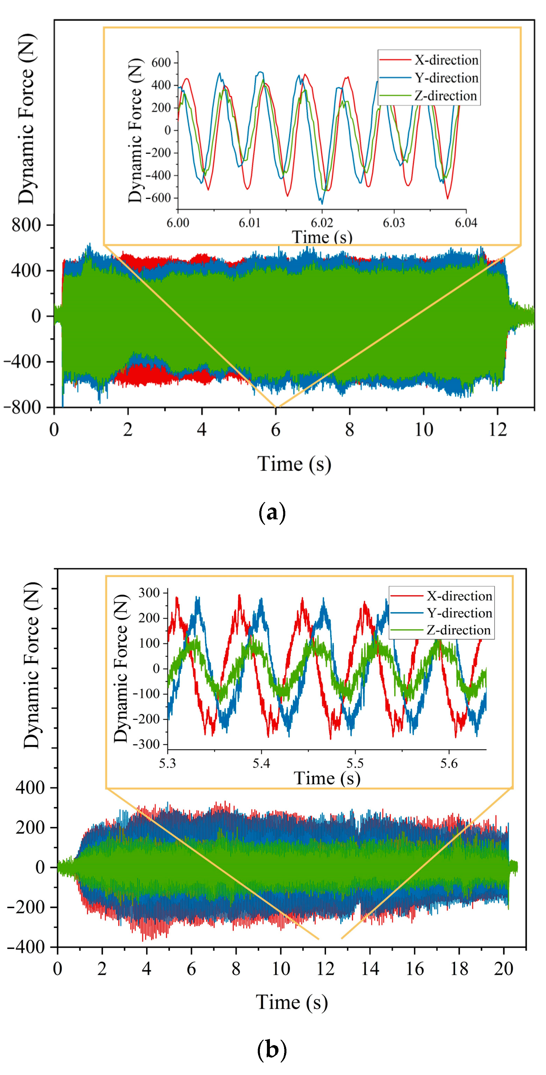
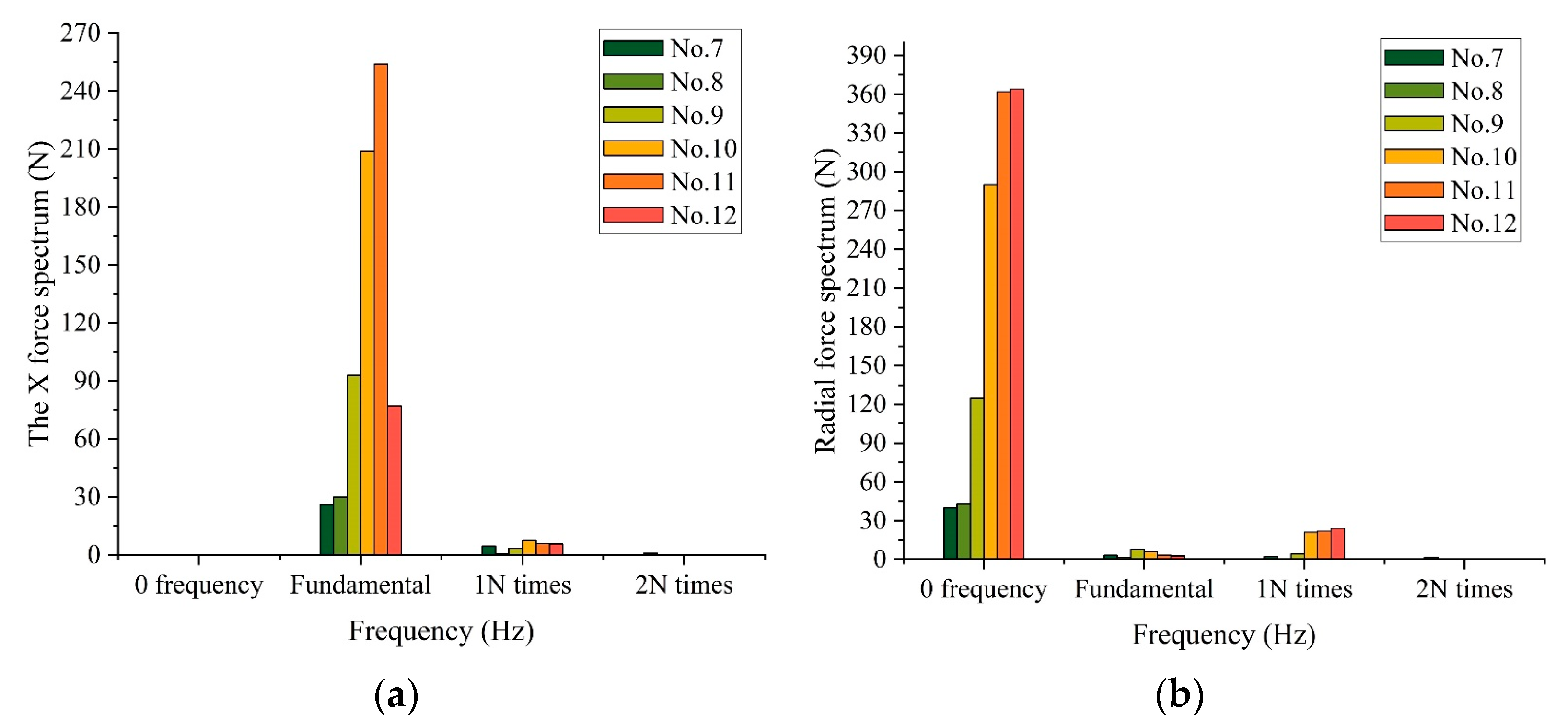
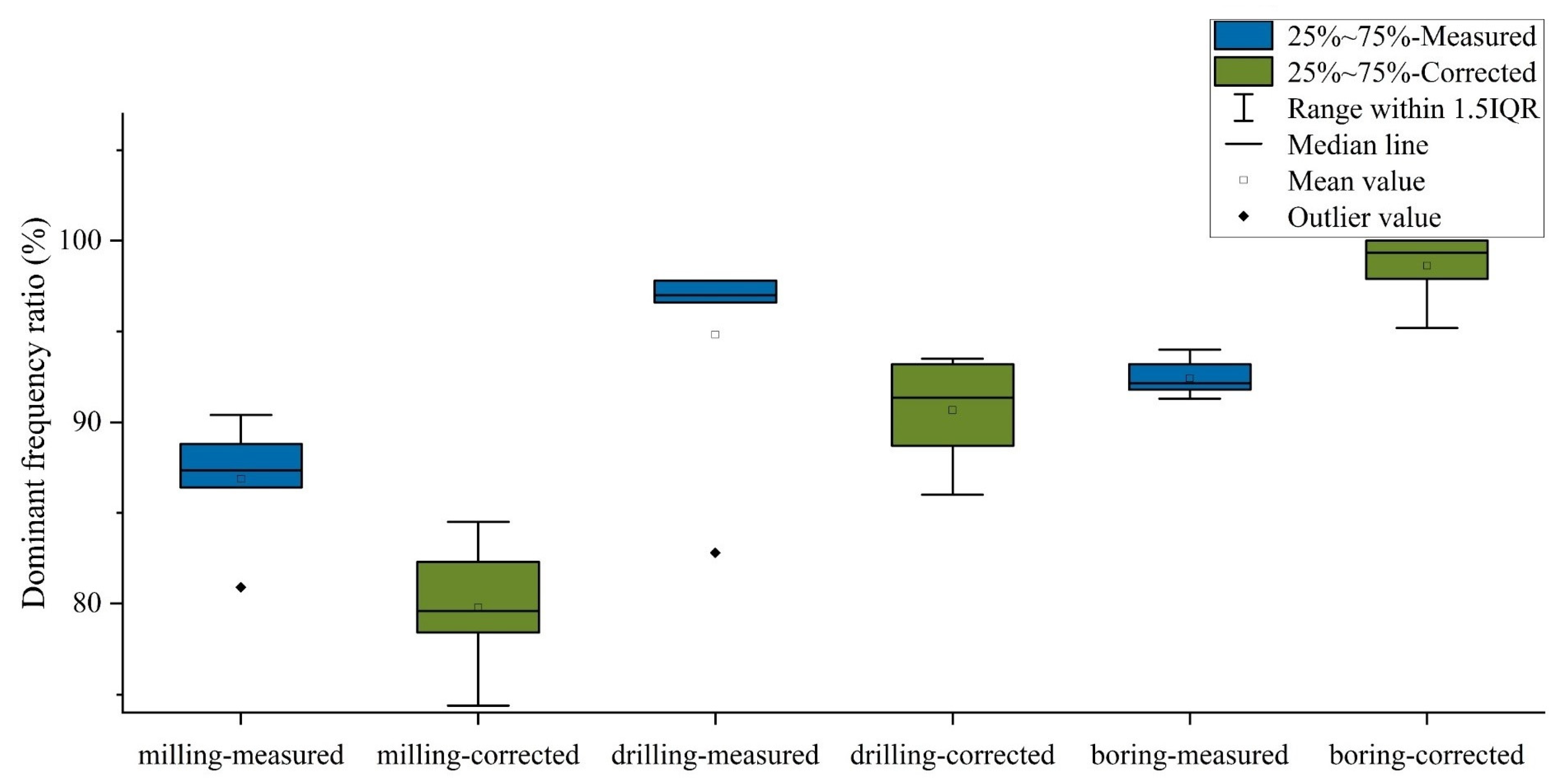
3.2. Verification of General Cutting Model of Spindle

The cutting force tests of milling, drilling, and boring are conducted to verify the general cutting model of the spindle established in this paper. A total of 18 groups of typical processes (Table 1) are selected from the process data collected by an engine parts manufacturing company. The machining is performed in the CNC machining center (VDL-1000), the load data are measured by Kistler-9129A dynamometer, and the real-time acquisition and display of the dynamic cutting force is realized by the software system of Dyno-Ware.
Figure 10 displays 3 out of 18 measured XYZ cutting forces regarding milling, drilling, and boring in Table 1, which intuitively display the time domain signals of cutting load. To analyze the frequency domain character, the 18 measured XYZ decomposition signals are transformed into the time domain by Fast Fourier Transform, as shown in Figure 11a, Figure 12a and Figure 13a. In addition, the measured loads in X and Y directions are converted into the radial direction, and the frequency spectrum is calculated using Fast Fourier Transform, such as Figure 11b, Figure 12b and Figure 13b.
In the machining test, the radial force of the spindle is characterized by measuring the force in the X- and Y-directions, and the force rules in the two directions are similar. However, the phase angle of the difference is π / 2 . Thus, only the X-direction is analyzed here.
The frequency-domain feature of the load data is extracted (X-direction load), and the frequency corresponding to the maximum load amplitude is set to the dominant frequency. The frequency spectrum of the 18 selected groups of processes is analyzed. The load pattern of milling is shown in Figure 11, and that of drilling and boring is, respectively, shown in Figure 12 and Figure 13. Figure 11a reveals that the dominant frequency of the X-direction is 1N times that of the spindle frequency, while Figure 11b shows that the dominant frequency of the radial resultant force is 0N times that of the spindle frequency.
The X force spectrum analysis of milling (Figure 11a) shows that the load frequency of milling is related not only to the fundamental frequency of the spindle speed but also to the number of teeth of the milling cutter (N times of the spindle rotation frequency). The load pattern of drilling and boring is, respectively, shown in Figure 12a and Figure 13a, and the load frequency of drilling and boring is only related to the fundamental frequency of the spindle speed. Except for the 0-frequency load (static component), the radial force spectrum analysis of the milling (Figure 11b) is mainly 1 N, 2 N, and 3 N times of the spindle rotation frequency, and the proportion of the fundamental frequency component of the same frequency as the spindle speed is substantially small. The main load component is 0 frequency (static component) in the radial force spectrum analysis of drilling and boring (Figure 12b and Figure 13b, respectively), and the other frequency loads are considerably small.
The largest difference between the load characteristics of the corrected model and the measured load lies in the bearing ball. Only the bearing ball is analyzed in this study as an example in the frequency spectrum. The proportion of the load power at the main frequency to the total load power is statistically analyzed, and the result is shown in Figure 14. Dominant frequency ratio (%) is the ratio of load amplitude at the dominant frequency to that of total amplitude, described as:
α = P 1 i = 1 n P i
where i is the harmonic frequency, P i is the Fourier coefficients at the ith harmonic frequency. When i = 1 , the Fourier coefficients at the 1st harmonic frequency is defined as the load at dominant frequency.
Figure 14 shows the Dominant frequency ratio under selected process (Table 1) in the XYZ coordinates. It can be seen that no matter the original load or the modified load, most of the energy of the load is the dynamic load on the dominant frequency; in addition, the proportion of the dominant frequency predicted by the modified load decreases slightly, but the dominant frequency predicted by the model accounts for more than 70% of all machining processes, indicating the good versatility of the load model. The following results are observed in the X-direction. The milling load accounts for a large proportion (more than 85%) in the product of spindle rotation frequency and milling cutter edge number (N times of the spindle rotation frequency), the drilling load accounts for more than 82% of the spindle rotation frequency, and the boring load accounts for more than 91% of the spindle rotation frequency. The amplitude of the load accounts for more than 72% in the zero frequency after combining the load vectors in the X- and Y-direction into the radial direction (R-direction). The comparison of the load frequency characteristics in the X- and R-directions revealed that the dynamic load in N times of the spindle rotation frequency is converted to zero frequency and becomes static load after the conversion of the measured dynamic load in the X- and Y-directions into the R-direction. The dynamic load composition decreases, which is consistent with the corrected general cutting load model proposed in this paper.
The above analysis indicates that the law shown in milling, drilling, boring, and cutting is the same as that of Equation (34). During milling, m = 1 ; thus, δ = 1 . The radial load, axial load, and torque, respectively, have 1N, 2N, and 3N times of the spindle rotation frequency in the general cutting load model. m = 2 and m = 3 during drilling and boring, respectively. The main load is static in this case, and the rest of the load can be ignored.
When the spindle is working, the components are subjected to the operation loads which are broad in frequency bandwidth. In this case, even if the stress amplitude is lower than the fatigue limit (Sr), the low amplitude load is accompanied by high frequency, which can also cause fatigue damage to the material. Therefore, when analyzing the spindle load, we should consider not only the actual amplitude of the load, but also its frequency.
In the same machine tool spindle, spindle vibration is tested under different RAT cutting load (radial force with static component and dynamic component proportional to rotation speed). The dynamic vibration is shown in Figure 15 (dynamic vibration is the ratio of the root mean square of the vibration to the amplitude of the dynamic force). The result shows that frequency is the main contributor to vibration. Therefore, as long as the proposed model has the right frequency component as the actual cutting, the load influence on vibration is promised.
A series of spindle fatigue research had been conducted in the field of durability tests and load spectrum. The load spectrum editing approaches for fatigue tests are based on the standard fatigue analysis theory (the S–N curve), the corresponding fatigue life can be deduced by the relationship between the stress amplitude and the number of stress cycles. Their research confirmed that the amplitude of load (calculated by cutting experiment) and load frequency are the main influence of spindle fatigue (reliability). The relationship between these two factors and spindle lifetime is determined after the whole-lifecycle test.
Therefore, the static and dynamic load frequency characteristics of the general load model are verified through the cutting experiments of milling, drilling, and boring in the CNC machining center. The proposed spindle general cutting load model in this paper can effectively reflect the load characteristics of different operations.
The main goal of this research is to discover the possible cutting load pattern for reliability test (e.g., how to composite and simplify cutting load regard with milling, drilling, and boring, and what kind of frequency component they have). As such, in the validation part, this study mainly focuses on whether the proposed RAT decomposition can represent the most kind of cutting load, which is the generality of the model. If a general model which can not only represent the cutting load pattern but is also easy to simulate with equipment is determined, the reliability test of the machine tool spindle can be conducted. Therefore, future work may pay more attention to the calculation of model parameters and also the verification of models for specific machining processes, which can make this research more complete.

4. Application of General Cutting Load Model for Spindle

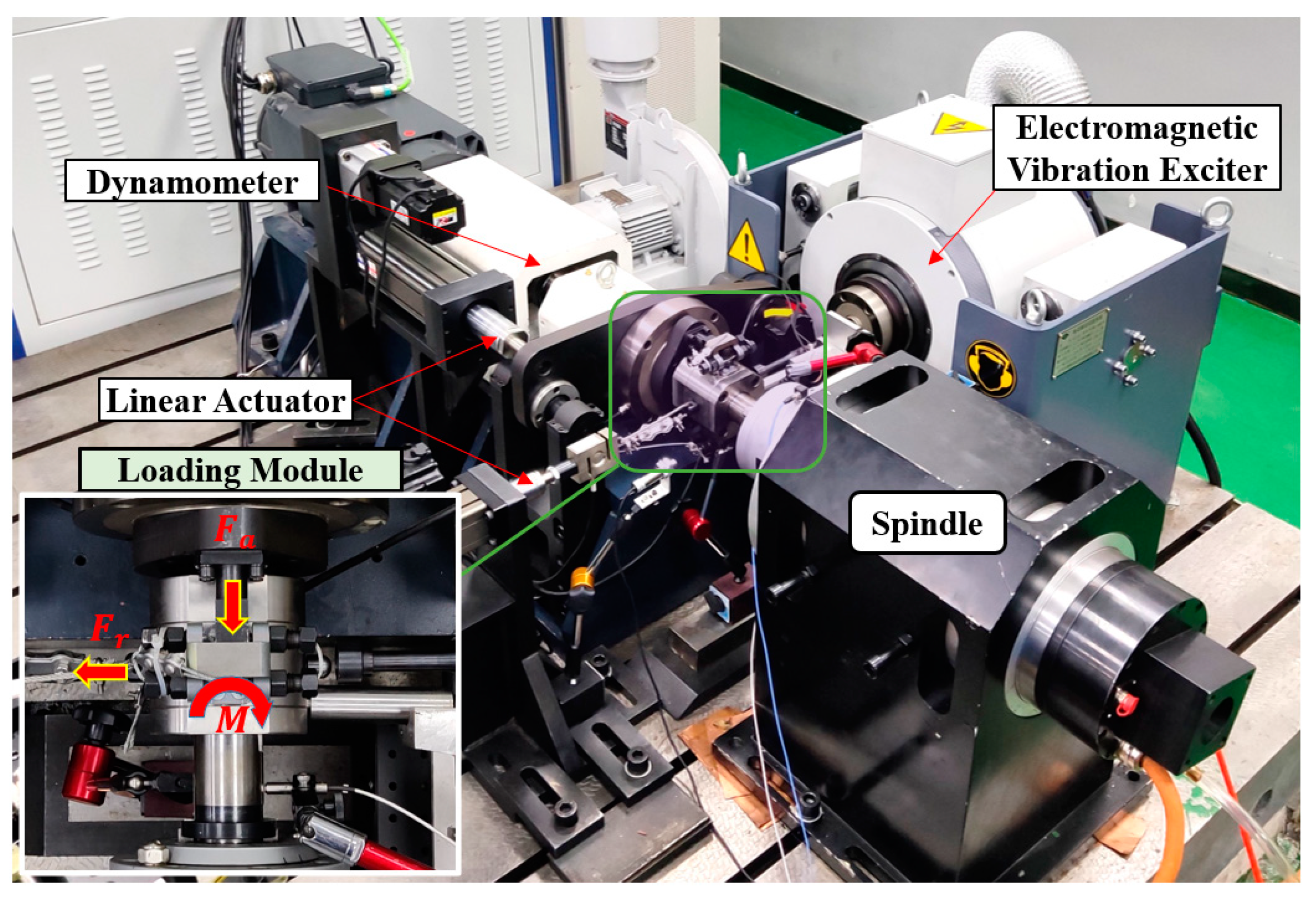
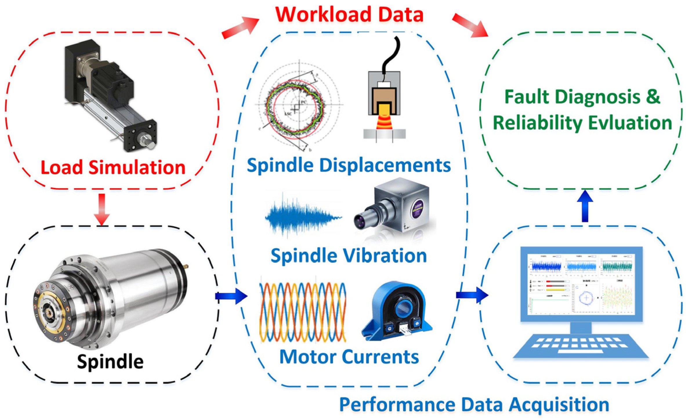
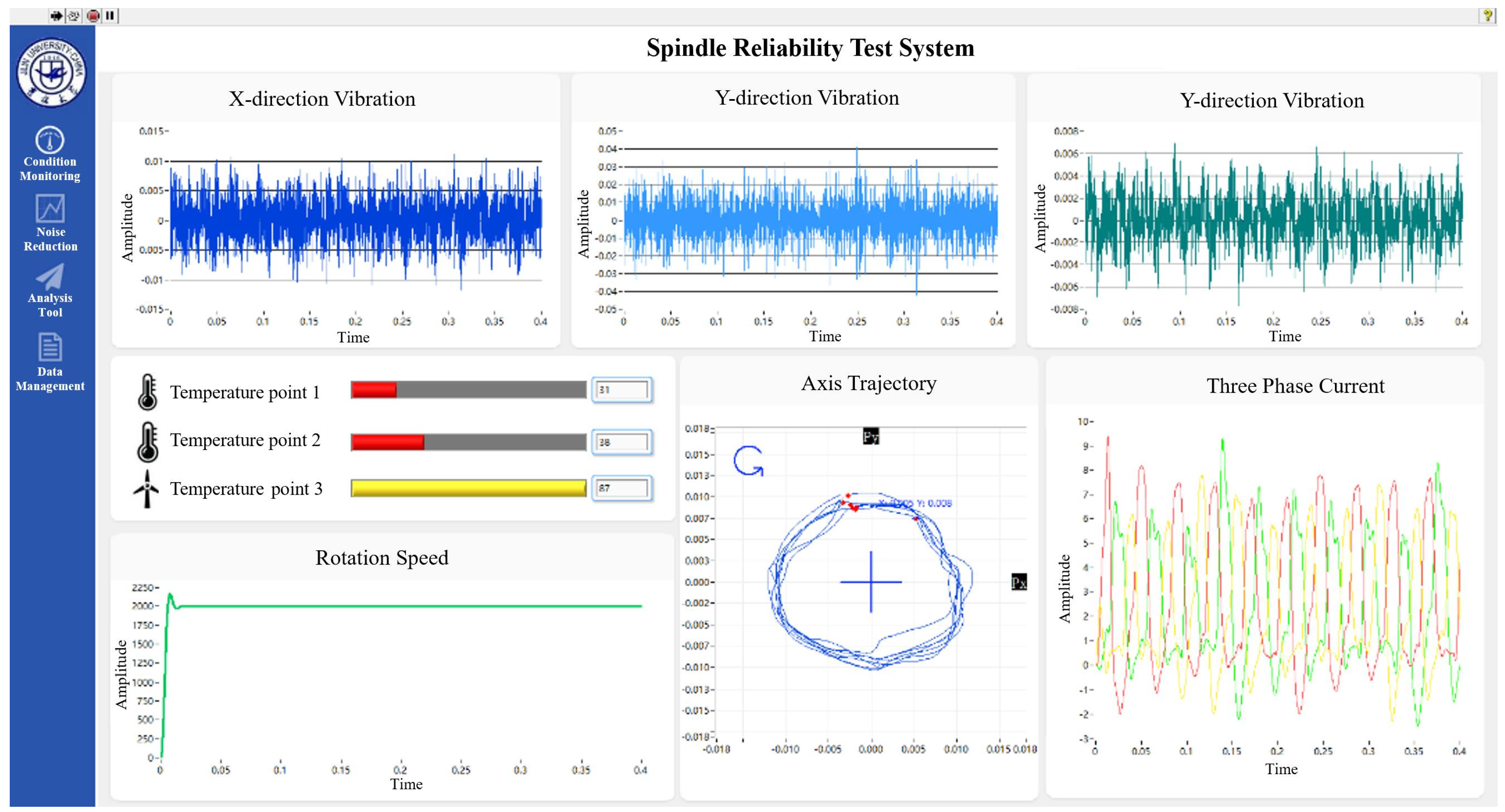
4.1. Design of Reliability Test-Bed for Testing and Leveling of Spindle

A spindle reliability test system with combined application of spindle radial force, axial force, and torque is developed in accordance with the characteristics of the general cutting load model for the spindle proposed in this paper. A 212-series motorized spindle made in China is tested in this spindle reliability test system. The data information of the spindle in the experiment is shown in the following Table 2. The test system comprises the following five modules: load transfer, static radial force loading, dynamic radial force loading, axial force loading, and torque loading. Among these modules, the load transfer module includes a simulation tool, a bearing unit, and a bellows coupling. The static radial force loading module applies the pulling force generated by the cylinder to the bearing unit through the wire rope. The dynamic radial force loading module is realized by an electromagnetic exciter with a high loading frequency and large dynamic amplitude range. The axial force loading module uses the electric cylinder to drive the thrust plate perpendicular to the spindle direction to apply it to the bearing unit. The torque loading module is simulated by the electric dynamometer, and the torque is applied to the spindle by the bellows coupling. The spindle reliability test can be conducted under RAT load decomposition through the test system. The physical diagram of the testbed is shown in Figure 16.
Comprehensively monitoring the spindle state in the process of spindle reliability test is necessary to detect the abnormal situation and immediately alarm and obtain the fault signal related to reliability. Figure 17 shows that the spindle rotation trajectory, bearing vibration, and motor current are measured simultaneously with load simulation and combined with anomaly identification and fault diagnosis algorithm, and online condition monitoring can be realized. The developed spindle reliability test system can realize the reliability and performance test of the spindle under load and provide a carrier for the practical application of the general cutting load model in the reliability test.

4.2. Reliability Test of Spindle

Loading different loads based on the test loading spectrum is necessary to conduct the spindle reliability test by using the spindle reliability test system developed in this paper. The experimental loading spectrum is compiled in this paper by using the load frequency characteristics in the general cutting model of the RAT spindle.
In order to ensure that the load data obtained from the test is in line with the actual production conditions, it is necessary to determine the process data for the test, and the process data are obtained from the actual production. The research team tracked an engine parts manufacturing company for 68 days and collected 1404 pieces of process data from 22 domestic machining centers. All the process data are calculated by empirical formula, and the statistics are performed in accordance with the operation. The distribution map of key working conditions to distinguish milling, drilling, and boring is obtained as shown in Figure 18.
The corresponding load is solved in accordance with the typical working condition and load model after collecting the working condition information, and the milling, drilling, and boring loading spectra are compiled. The three spectra are then combined into a total test loading spectrum according to proportion. Taking the 7012/CD angular contact ball bearing as an example (the bearing parameters are shown in Table 3), the general test eight-block loading spectrum of the engine parts is compiled in this paper as shown in Table 4.
The load spectrum is the pattern that guides the spindle reliability test. In machining, the cutting force on the spindle rotates along the radial direction (with the same frequency of spindle rotation speed). However, in the reliability test, the direction of the radial force is simplified as a constant. In order to calculate loading cycles in the reliability test, it is necessary to determine the equivalent frequency regarding different spindle components, which is called “frequency of the load spectrum” in this research.
In Table 4, the frequency of radial force is modified as f M . f M ( M = 1 ,   2 ,   3 ) is defined as the frequency of the load spectrum compiled in accordance with the corrected general cutting load model, f is the loading frequency of the uncorrected model, f 1 ( M = 1 ) is the corrected loading frequency based on the bearing ball damage as the standard application, f 2 ( M = 2 ) is the corrected loading frequency based on the bearing outer race damage as the standard application, f 3 ( M = 3 ) is the corrected loading frequency based on the bearing inner race damage, rotating spindle, motor, and other parts as the standard application. Table 4 shows that the loading frequency of different components varies when different components are selected as the standard of spindle fatigue damage under similar rotating tool speed and loading time. Therefore, the fatigue damage is different.
The spindle reliability test is performed on the spindle reliability test system using the test loading spectrum compiled by the general cutting load model for spindle in RAT coordinate. During the reliability test, the condition monitoring signal including vibration, bearing temperature, spindle speed, axis trajectory, and current are captured (see Figure 19), which provides basic data for reliability evaluation.
The spindle reliability test system is developed in accordance with the general cutting load model based on the RAT decomposition proposed in this paper. Moreover, the spindle reliability test loading spectrum is compiled by using the corrected spindle cutting load model, the spindle reliability test is successfully conducted, and the practical engineering application of the spindle general cutting load model is realized.

5. Conclusions

To consider the versatility, maneuverability, and accuracy of the load model when applied in the spindle reliability test, this paper introduces a general cutting load model in the RAT composition and eliminates the rotational character of radial force. A reliability test platform and corresponding load spectrum are proposed which can be used to guide the reliability test. (1) First, the load micro-element model is established in accordance with the metal cutting principle. Then, the cutting load model based on RAT decomposition is proposed. This model converts the complex spatial load into the RAT form and is easily simulated by engineering. Finally, a general cutting load model is established in accordance with the cutting load characteristics of different operations to describe the spindle milling, drilling, and boring operations.
(2) This paper scientifically analyzes the relationship between the loading frequency of the bearing components on the reliability test platform and the loading frequency in the actual working process. The relative relationship of fatigue cumulative times of the bearing between the rotating radial and static forces under different conditions is deduced, and the general cutting load model is corrected following this law. The spindle cutting test is performed in the CNC machining center under typical working conditions, and the load cutting model is verified. In the spectrum analysis of each processing mode, more than 70% of the load energy predicted by the load model is at the main frequency, which shows that the load model has good versatility.
(3) A spindle reliability test system with combined application of spindle radial force, axial force, and torque is developed in accordance with the RAT cutting load model. The test loading spectrum is compiled by using factory statistical data and is corrected using the proposed frequency transformation relationship. With the help of the above test system and modified loading spectrum, the spindle reliability test can be successfully conducted.
Creating a general cutting load model is a wish for many researchers in manufacturing. This research only takes a little step and mainly focuses on determining a practical model to guide the spindle reliability test. However, there is still some follow-up work to be done. Firstly, the method for determining the specific parameters in the RAT cutting load model needs to be discussed and studied. Furthermore, the typicality of the process is not accurate enough, which will directly affect the compilation of the load spectrum, so more processing processes need to be collected and analyzed. In addition, the effectiveness of establishing the load model should be further verified when obtaining enough reliability and degradation test data.

Author Contributions

Conceptualization, W.C.; methodology, L.K. and W.C.; resources, Z.Y.; data curation, L.K.; writing—original draft preparation, L.K.; writing—review and editing, L.K. and C.C.; supervision, Z.Y.; project administration, W.L.; funding acquisition, W.L. All authors have read and agreed to the published version of the manuscript.

Funding

This work is supported by the Jilin Province Science and technology development plan project (20210508053RQ) and National Natural Science Foundation of China (Grant No. 51975249).

Institutional Review Board Statement

Not applicable.

Informed Consent Statement

Not applicable.

Data Availability Statement

Not applicable.

Conflicts of Interest

The authors declare no conflict of interest.

References

  1. Li, Y.; Zhang, X.; Ran, Y.; Zhang, G. Reliability modeling and analysis for CNC machine tool based on meta-action. Qual. Reliab. Eng. Int. 2021, 37, 1451–1467. [Google Scholar] [CrossRef]
  2. Wang, Y.; Jia, Y.; Qiu, J.; Shen, G. Load spectra of CNC machine tools. Qual. Reliab. Eng. Int. 2000, 16, 229–234. [Google Scholar] [CrossRef]
  3. Ehmann, K.F.; Kapoor, S.G.; Devor, R.E.; Lazoglu, I. Machining Process Modeling: A Review. J. Manuf. Sci. Eng. 1997, 119, 655–663. [Google Scholar] [CrossRef]
  4. Liu, X.W.; Cheng, K.; Webb, D.; Luo, X.C. Improved Dynamic Cutting Force Model in Peripheral Milling. Part I: Theoretical Model and Simulation. Int. J. Adv. Manuf. Technol. 2002, 20, 631–638. [Google Scholar] [CrossRef]
  5. Roukema, J.C.; Altintas, Y. Kinematic Model of Dynamic Drilling Process. In Proceedings of the ASME International Mechanical Engineering Congress and Exposition, Anaheim, CA, USA, 13–19 November 2004; pp. 955–963. [Google Scholar] [CrossRef]
  6. Yussefian, N.Z.; Moetakef-Imani, B.; El-Mounayri, H. The prediction of cutting force for boring process. Int. J. Mach. Tools Manuf. 2008, 48, 1387–1394. [Google Scholar] [CrossRef]
  7. Williams, J.A. Mechanics of Machining: An Analytical Approach to Assessing Machinability; Halsted Press: Chichester, UK, 1989. [Google Scholar] [CrossRef] [Green Version]
  8. Tapoglou, N. Development of Cutting Force Model and Process Maps for Power Skiving Using CAD-Based Modelling. Machines 2021, 9, 95. [Google Scholar] [CrossRef]
  9. van Luttervelt, C.A.; Childs, T.; Jawahir, I.; Klocke, F.; Venuvinod, P.; Altintas, Y.; Armarego, E.; Dornfeld, D.; Grabec, I.; Leopold, J.; et al. Present Situation and Future Trends in Modelling of Machining Operations Progress Report of the CIRP Working Group ‘Modelling of Machining Operations’. CIRP Ann. Manuf. Technol. 1998, 47, 587–626. [Google Scholar] [CrossRef]
  10. Adetoro, O.B.; Wen, P.H. Prediction of mechanistic cutting force coefficients using ALE formulation. Int. J. Adv. Manuf. Technol. 2010, 46, 79–90. [Google Scholar] [CrossRef]
  11. Huang, C.Y.; Wang, J. Mechanistic Modeling of Process Damping in Peripheral Milling. J. Manuf. Sci. Eng. 2007, 129, 397–406. [Google Scholar] [CrossRef]
  12. Kaymakci, M.; Kilic, Z.M.; Altintas, Y. Unified cutting force model for turning, boring, drilling and milling operations. Int. J. Mach. Tools Manuf. 2012, 54–55, 34–45. [Google Scholar] [CrossRef]
  13. Altintas, Y.; Kilic, Z.M. Generalized dynamic model of metal cutting operations. CIRP Ann. Manuf. Technol. 2013, 62, 47–50. [Google Scholar] [CrossRef]
  14. Kilic, Z.M.; Altintas, Y. Generalized mechanics and dynamics of metal cutting operations for unified simulations. Int. J. Mach. Tools Manuf. 2016, 104, 1–13. [Google Scholar] [CrossRef]
  15. Guo, J.; Dan, W.; Chen, W.; Fan, R. Multi-Axis Loading Device for Reliability Tests of Machine Tools. IEEE/ASME Trans. Mechatron. 2018, 23, 1930–1940. [Google Scholar] [CrossRef]
  16. Ding, Z.; Yang, Z.; Chen, C.; Chen, W.; Chen, H.; Liu, Z. Improved sliding mode dynamic matrix control strategy: Application on spindle loading and precision measuring device based on piezoelectric actuator. Mech. Syst. Signal Process. 2021, 167, 108543. [Google Scholar] [CrossRef]
  17. Chen, W.; Yang, Z.; Chen, C.; Luo, W. Load-Dependent Rotating Performance of Motorized Spindles: Measurement and Evaluation using Multi-Zones Error Map. IEEE Access 2019, 7, 180482–180490. [Google Scholar] [CrossRef]
  18. Kilic, Z.M.; Altintas, Y. Generalized modelling of cutting tool geometries for unified process simulation. Int. J. Mach. Tools Manuf. 2016, 104, 14–25. [Google Scholar] [CrossRef]
  19. Lamikiz, A.; de Lacalle, L.L.; Sánchez, J.; Salgado, M. Cutting force estimation in sculptured surface milling. Int. J. Mach. Tools Manuf. 2004, 44, 1511–1526. [Google Scholar] [CrossRef]
  20. Keer, L.M.; Bryant, M.D. A Pitting Model for Rolling Contact Fatigue. J. Lubr. Technol. 1983, 105, 198. [Google Scholar] [CrossRef]
Figure 1. Schematics of chip removal at the cutting edges element.
Machines 10 00144 g001
Figure 2. Segment of insert in different basic machining operations.
Machines 10 00144 g002
Figure 3. Coordinate system transformation of load microelement. (a) the load in the chip flow (U,V) coordinates. (b) the load in the Radial-Tangential-Axial (RTA) coordinates of the tool. (c) the load in the spindle reference (RAT) coordinate.
Machines 10 00144 g003
Figure 4. Mechanics of oblique cutting.
Machines 10 00144 g004
Figure 5. Insert position diagram caused by runout.
Machines 10 00144 g005
Figure 6. Schematic of cutting load pattern in different machining processes. (a) Load condition of milling. (b) Load condition of drilling. (c) Load condition of boring.
Machines 10 00144 g006
Figure 7. Schematic diagram of spindle parts under load.
Machines 10 00144 g007
Figure 8. Force distribution on loaded balls.
Machines 10 00144 g008
Figure 9. Calculation relation diagram of fatigue times of bearing balls. (a) Bearing motion relationship in machine tool coordinates. (b) Bearing motion relationship in RAT coordinate system.
Machines 10 00144 g009
Figure 10. Measured time-domain cutting force. (a) Milling load amplitude and frequency spectrum. Tungsten steel body tool, 4 inserts, 10 mm diameter cutter, n f = 2700   r/min , v f = 200   mm/min , a p = 3   mm . (b) Drilling load amplitude and frequency spectrum. Arbide tool, 2 inserts, 16 mm diameter cutter −8 mm guide hole, n f = 900   r/min , v f = 60   mm/min , a p = 4   mm . (c) Boring load amplitude and frequency spectrum. Carbide tool, Single insert, Bore, Diameter-34 mm, n f = 540   r/min , v f = 60   mm/min , a p = 1.5   mm .
Machines 10 00144 g010aMachines 10 00144 g010b
Figure 11. Frequency spectrum analysis of milling cutting load. (a) Force in X-direction. (b) Resultant force in radial direction.
Machines 10 00144 g011
Figure 12. Frequency spectrum analysis of drilling cutting load. (a) Force in X-direction. (b) Resultant force in radial direction.
Machines 10 00144 g012
Figure 13. Frequency spectrum analysis of boring cutting load. (a) Force in X-direction. (b) Resultant force in radial direction.
Machines 10 00144 g013
Figure 14. Box diagram of the dominant frequency of load under different processes.
Machines 10 00144 g014
Figure 15. Spindle vibration under different rotation speed and static force.
Machines 10 00144 g015
Figure 16. Spindle reliability test bed.
Machines 10 00144 g016
Figure 17. Condition monitoring of spindle reliability test.
Machines 10 00144 g017
Figure 18. Distribution of key working conditions in different operations. (a) Distribution of milling. (b) Distribution of drilling. (c) Distribution of boring.
Machines 10 00144 g018
Figure 19. Reliability test results of spindle.
Machines 10 00144 g019
Table 1. Experimental design of different workload conditions.
Machining Process
No.OperationTool TypeTool
Material
Tooth
Number
Cutter
Diameter
(mm)
Spindle Speed (r/min)Depth of Cut (mm)Feed Speed
(mm/min)
1MillingHelical End MillsAlloy tool steel289003200
2Helical End MillsAlloy tool steel2818003100
3Helical End MillsAlloy tool steel2818006100
4Helical End MillsAlloy tool steel2827006200
5Helical End MillsCemented carbide489006100
6Helical End MillsCemented carbide41027003200
7DrillingTwist drillAlloy tool steel281800-120
8Twist drillAlloy tool steel282700-30
9Twist drillAlloy tool steel2161800-120
10Twist drillAlloy tool steel216900-60
11Twist drillAlloy tool steel2161800-60
12Twist drillAlloy tool steel2162700-120
13BoringRough boringHigh-speed steel1223600.920
14Rough boringHigh-speed steel1265400.920
15Rough boringHigh-speed steel1345401.560
16Rough boringHigh-speed steel1403601.240
17Rough boringHigh-speed steel1461801.240
18Rough boringHigh-speed steel1521801.560
Table 2. The parameters of 212-series motorized spindle.
PowerMaximum SpeedRated TorqueVoltageLubricationCoolingRadial RunoutAxial Movement
11 kW12,000 rpm35N·m380 VGreaseWater cooling≤0.004 mm≤0.002 mm
Table 3. Structural parameters of angular contact ball bearing 7012/CD.
Structural ParametersValue
Inner diameter of bearing d/mm60
Outer diameter of bearing D/mm95
Rolling element diameter Db/mm9.525
Bearing pitch diameter dm/mm77.5
Radius of locus of inner raceway groove Curvature centers ri/mm4.95
Outer diameter of inner ring da/mm67.5
Radius of locus of outer raceway groove Curvature centers re/mm4.95
Initial contact angle, °15
Number of balls Z18
Table 4. Loading spectrum based on general load model in RAT coordinates.
Block No.12345678
Static radial force F r m e a n 217520671806121611249861494339
dynamic radial force F r a m p 17201617142892293564227209
axial force F z −450−428−386−285−205−120−247−24.50
torque M m e a n 35.3033.6029.4017.606.104.202.101.10
the speed of rotating tool n 60060060012002200180022003500
Uncorrected loading frequency f 40404080110120147233
Corrected loading frequency of the ball f 1 10.4010.4010.4020.8028.6031.2038.2260.58
Corrected loading frequency of the bearing outer race f 1 40404080110120147233
Corrected loading frequency of the bearing inner race f 3 44443444
Loading time0.501.100.832.3021.9511.4141.4880.45
Publisher’s Note: MDPI stays neutral with regard to jurisdictional claims in published maps and institutional affiliations.

