Article

Effect of Assembly Errors on Ground Tooth Surface Deviations for Large-Scale CNC Gear Profile Grinding Machines

1
Jiangsu Key Laboratory of Advanced Numerical Control Technology, Nanjing Institute of Technology, Nanjing 211167, China
2
Nanjing Gongda CNC Technology Co., Ltd., Nanjing 211816, China
*
Author to whom correspondence should be addressed.
Machines 2022, 10(2), 111; https://doi.org/10.3390/machines10020111
Submission received: 30 December 2021 / Revised: 22 January 2022 / Accepted: 28 January 2022 / Published: 1 February 2022
(This article belongs to the Section Advanced Manufacturing)

Abstract

:
Assembling plays a significant role in the performance of large-scale CNC gear profile grinding machines. An approach in the deviation evaluation of ground tooth surfaces taking into account assembly errors is proposed in this paper. Based on the error transmission chain of the profile grinding system and the conjugate motion relationship between the grinding wheel and the workpiece, the ground tooth surface model including assembly errors was established using the surface envelope method. Then, the effect of assembly errors on deviations of the profile grinding tooth surface was quantitatively analyzed. The optimized distribution of assembly errors and machining verifications were performed on large-scale CNC gear profile grinding machines. The results show that the proposed method is effective at ensuring ground tooth surface deviations for large-scale CNC gear profile grinding machines.

1. Introduction

Large module precision gears with hardened tooth surfaces are widely used in the fields of wind power, ships, engineering machinery, etc. The tooth surface accuracy directly affects the performance and lifetime of the equipment seriously, such as transmission accuracy, transmission efficiency, and transmission noise. Grinding is suitable for manufacturing in hard materials because of the abrasive grains’ hardness and their stout cutting wedges with negative rake angles [1]. Laser technology imposes pressure in grinding for hard materials’ manufacturing. However, it has higher costs [2]. In many industrial applications, grinding processes are often the final step in the process towards finished workpieces, which means that no subsequent postgrinding correction of the surface and geometry is performed [3]. Therefore, grinding is the most important finishing process in manufacturing large module precision gears with hardened tooth surfaces.
From 1961 to the present day, researchers have made advances in many areas of grinding technology, such as process principles, machine design, tool design, process optimization, and control technology. Nevertheless, grinding today still requires test pieces to begin a long process run, which clearly indicates the necessity of grinding research and development in grinding machines [4]. Grinding machines can be classified into belt-grinding machines, stroke grinding machines, and grinding machines with rotating tools. A further level of classification for grinding machines with rotating tools distinguishes between cylindrical, planar, tool, and gear grinding machines [5].
There are two primary productive methods for gear grinding machines: the profile grinding method and the generating grinding method [6]. The profile grinding method, a single-indexing process, was developed by Niles, Gleason-Pfauter, and Luren Precision; the generating grinding method, a continuous-indexing process was developed by Reishauer and Gleason [7]. These two methods use different tools: a form wheel and a worm wheel. The rotation angles of the wheel and the workpiece are independent in the former but have a timed relationship in the latter. To meet the demands of the large module gears used, profile correction is especially needed for application on tooth surfaces to increase the gear load capability and to reduce noise [8]. One major concern in gear grinding machine is how to flexibly produce the gears with profile correction. The profile grinding method is more powerful than the generating grinding method for manufacturing large module gears with profile correction, especially when the CNC gear profile grinding machine is developed, because it has enough degrees of freedom to modify the tooth surfaces. Furthermore, the profile grinding method can achieve a high grinding efficiency due to line contact between the grinding wheel and the gear in this process [9]. A CNC gear profile grinding machine not only offers a simultaneous five-axis movement that enables free-form grinding but also includes an NC dressing device for wheel profile modification, so it is suitable for finishing large module gears.
The ground tooth surface deviations are the major target parameter for a gear profile grinding machine, and they are mainly caused by grinding interference and machine errors (including assembly errors, geometric errors, and thermal errors) [4]. The former can be reduced by adjusting setting the parameters and radius of the wheel. However, the latter is more complex. Compared with geometric errors and thermal errors, the assembly errors vary little over time. It is an effective way to control the ground tooth surface deviations by optimizing the assembly errors. Therefore, it is very beneficial to understand the mapping relationship between assembly errors and ground tooth surface deviations, but there is little literature published about it.
In the related literature, the geometric errors were first investigated and a model of a CNC gear profile grinding machine was then established to predict and compensate for geometric errors [10,11]. Subsequently, thermal error compensation was used to improve the gear grinding accuracy. A theoretical model of thermal errors for transmission chain in the large CNC gear profile grinding machine was proposed to guide the error compensation [12]. The influence of thermal errors on pitch errors was investigated successively, and a cross-tooth index machining method was proposed to reduce the pitch errors [13]. In extensive research, Zhang et al. presented a motion control method to improve the gear grinding accuracy. The minimum difference between the actual topological deviations of the tooth surface and the target topological deviations was taken as the optimization objective, and then, the tooth surface distortion resulting from tooth orientation modification was effectively eliminated by optimizing the five-axis motion control of the gear grinding machine [14]. An evaluation approach for tooth orientation modification errors of profile grinding gears was developed, and an optimization method adjusting the installation parameters of grinding wheel and workpiece was proposed, which effectively reduced the tooth direction modification errors of helical gears [15]. More recently, the reasonable selection of grinding wheel installation angles and grinding wheel radius was proposed as another feasible method. Ding et al. judged the grinding interference by computing the induced normal curvature, which is any point of the contact line between the grinding wheel surface and the gear surface, and then the setting parameters of grinding wheel were obtained under the condition of grinding without interference [16]. The contact line of the profile grinding wheel investigated by Li et al. and the optimal installation angle of the grinding wheel were accurately calculated. The machining efficiency was improved, and the grinding interference was avoided at this optimal installation angle [17]. Ding et al. investigated the assembly errors of a five-axis machine tool based on the homogeneous coordinate transformation method, and the assembly errors were compensated in NC codes through reverse decoupling [18]. The influence of assembly errors on the motion accuracy was analyzed for feed systems of CNC machine tools [19]. Lee et al. investigated the effect of assembly errors on volumetric errors for a five-axis machine tool, and they recognized the error terms that cannot be compensated by driving single control axis [20]. Nevertheless, tooth surface deviations in profile grinding were not referred to in the above work. Xia et al. proposed a model of tooth surface deviations and geometric errors for a five-axis gear profile grinding machine, and critical errors and sensitive components were identified by sensitivity analysis method [21]; however, assembly errors were not referred to in that research.
Assembly errors should especially be considered in large-scale CNC gear profile grinding machines for finish machining. On one hand, assembly errors are affected by the dimensional tolerances of assembly parts. Smaller assembly errors are bound to require higher accuracy of assembly parts. An excessively high accuracy is difficult to manufacture, and the machining cost will increase sharply [4,22,23]. On the other hand, assembly operations of large machines are more difficult with respect to conventional size machines and need to be addressed. Looser assembly errors are beneficial for the assembling of large-scale CNC gear profile grinding machines [24,25,26,27]. The objective of this paper is to analyze and optimally distribute assembly errors of large-scale CNC gear profile grinding machines in terms of ground tooth surface deviations.
The structure of the rest of this paper is as follows. Tooth surface modeling including assembly errors is described in detail in Section 2. Section 3 proposes an approach to evaluate tooth surface deviations in gear profile grinding. Calculation analysis and experiment are presented in Section 4. Finally, Section 5 provides the conclusions.

2. Tooth Surface Modeling including Assembly Errors

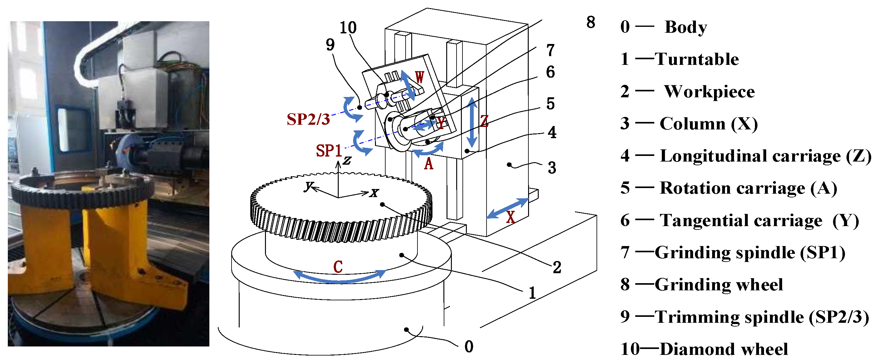
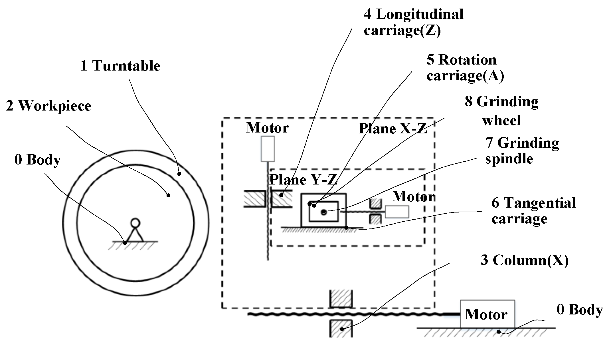
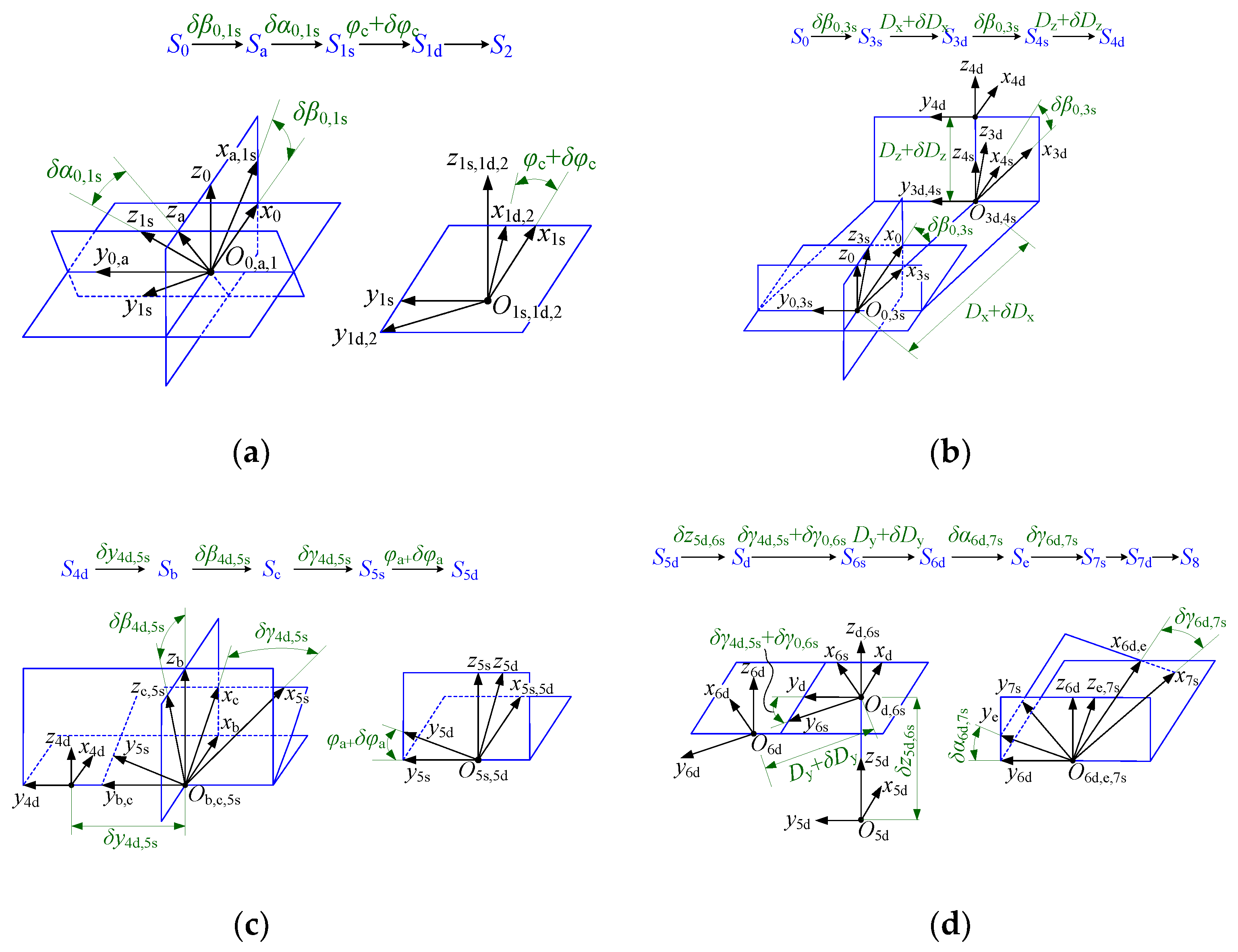
2.1. Assembly Errors of Grinding System

As shown in Figure 1, the large CNC gear profile grinding machine has four translations axes and two rotation axes. The X axis is along the column movement direction. The Y axis is parallel to the grinding wheel rotation axis. The Z axis is parallel to the workpiece rotation axis. The W axis is parallel to the radial direction of the grinding wheel. The grinding spindle swing is the A axis, and the workpiece rotation is the C axis. In addition, there are three spindles: grinding spindle SP1, and dressing spindles SP2 and SP3. The gear grinding system includes the X axis, the Y axis, the Z axis, the A axis, the C axis, and SP1. The grinding wheel dressing system includes the Y axis, the W axis, SP2, and SP3. Before grinding can take place, the grinding wheel must be dressed by the diamond roller with the simultaneous movement of the grinding wheel dressing system. The kinematic chain of the gear grinding system (shown in Figure 2) is more complex than that of the grinding wheel dressing system. Therefore, assembly errors of the gear grinding system are highlighted in this paper.
To investigate the effect of assembly errors on ground tooth surface deviations, the coordinate system transformation with assembly errors was established to describe the spatial relationship between critical components. In Figure 3, S represents the coordinate system. The number in the subscript of S represents the corresponding component in Figure 2, and the small s and d attached to the number represent the stationary coordinate system and the moving coordinate system of the same component, respectively. Sa, Sb, Sc, and Sd are auxiliary coordinate systems. The assembly errors of the gear grinding system are shown in Table 1.

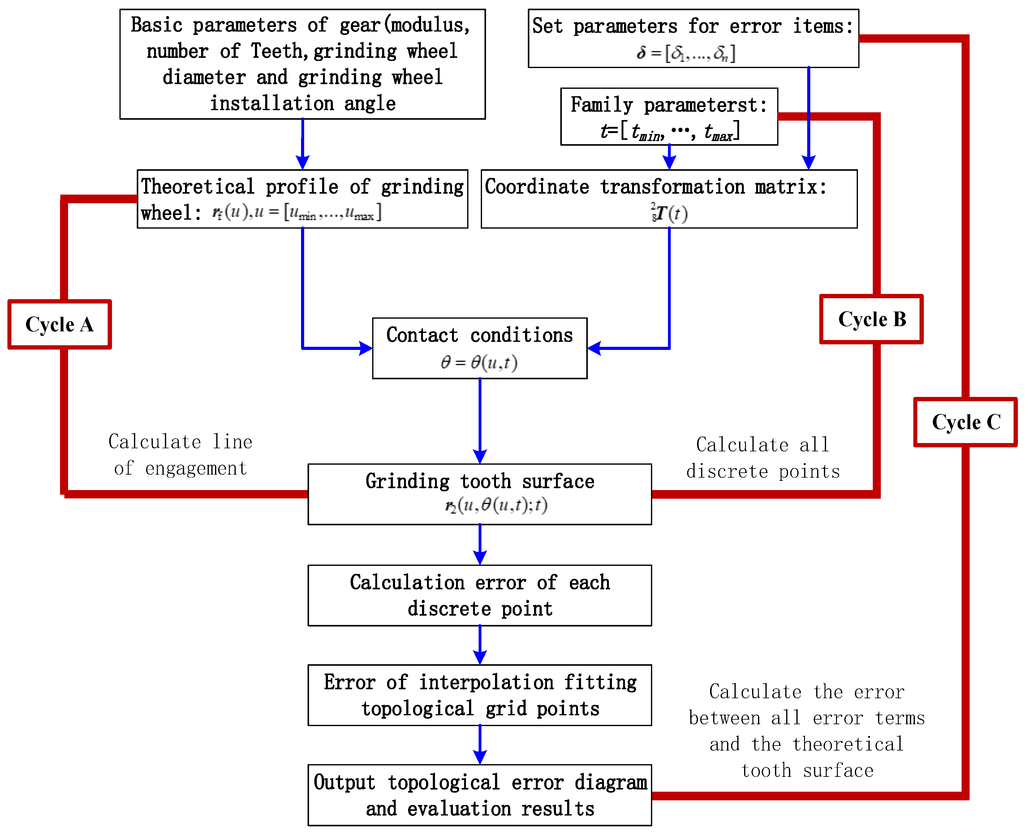
2.2. Modeling of Gear Profile Grinding Motion

The process of gear profile grinding can be described by a mathematical model of position and posture about the grinding wheel relative to the workpiece. This model includes the above assembly errors, which can be expressed as follows:
r 2 ( u , θ ; t ) = T 8 2 ( t ) r 8 ( u , θ )
where r 8 ( u , θ ) is the position vector of the grinding wheel surface in the tool coordinate system S8; u and θ are the two shape parameters of the surface; r 2 ( u , θ ; t ) is the single-parameter surface family of the grinding wheel in S2 during a grinding motion; and t is the motion parameter of surface family. T 8 2 ( t ) is the homogeneous coordinate transformation matrix from S8 to S2, and it can be derived as follows:
T 8 2 ( t ) = T 1 d 2 T 1 s 1 d ( φ c + δ φ c ) T a 1 s ( δ α 0 , 1 s ) T 0 a ( δ β 0 , 1 s ) T 3 s 0 ( δ β 0 , 3 s ) T 3 d 3 s ( D x + δ D x ) T 4 s 3 d ( δ β 0 , 3 s ) T 4 d 4 s ( D z + δ D z ) T b 4 d ( δ y 4 d , 5 s ) T c b ( δ β 4 d , 5 s ) T 5 s c ( δ γ 4 d , 5 s ) T 5 d 5 s ( φ a + δ φ a ) T d 5 d ( δ z 5 d , 6 s ) T 6 s d ( δ γ 4 d , 5 s + δ γ 0 , 6 s ) T 6 d 6 s ( D y + δ D y ) T e 6 d ( δ β 6 d , 7 s ) T 7 s e ( δ α 6 d , 7 s ) T 7 d 7 s T 8 7 d
In Equation (2), the coordinate transformation matrixes between two adjacent coordinate systems can be derived according to the relationship illustrated in Figure 3, and they are summarized in Table 2.
As shown in Figure 4, the grinding wheel surface is regarded as being swept by its axial profile h-h’ while the coordinate system Sf rotates about O8y8 axis. x f ( u ) and y f ( u ) are coordinates of the grinding wheel axial profile h-h’ in the gding wheel axial coordinate system Sf. At the beginning, Sf coincides with S8. Therefore, the grinding wheel surface can be expressed as follows:
r 8 ( u , θ ) = Τ f 8 ( θ ) r f ( u )
where
r f ( u ) = [ x f ( u ) , y f ( u ) , 0 , 1 ] T , T f 8 ( θ ) = [ cos ( θ ) 0 sin ( θ ) 0 0 1 0 0 sin ( θ ) 0 cos ( θ ) 0 0 0 0 1 ]
Figure 4. Wheel surface swept by its axial profile.
Machines 10 00111 g004

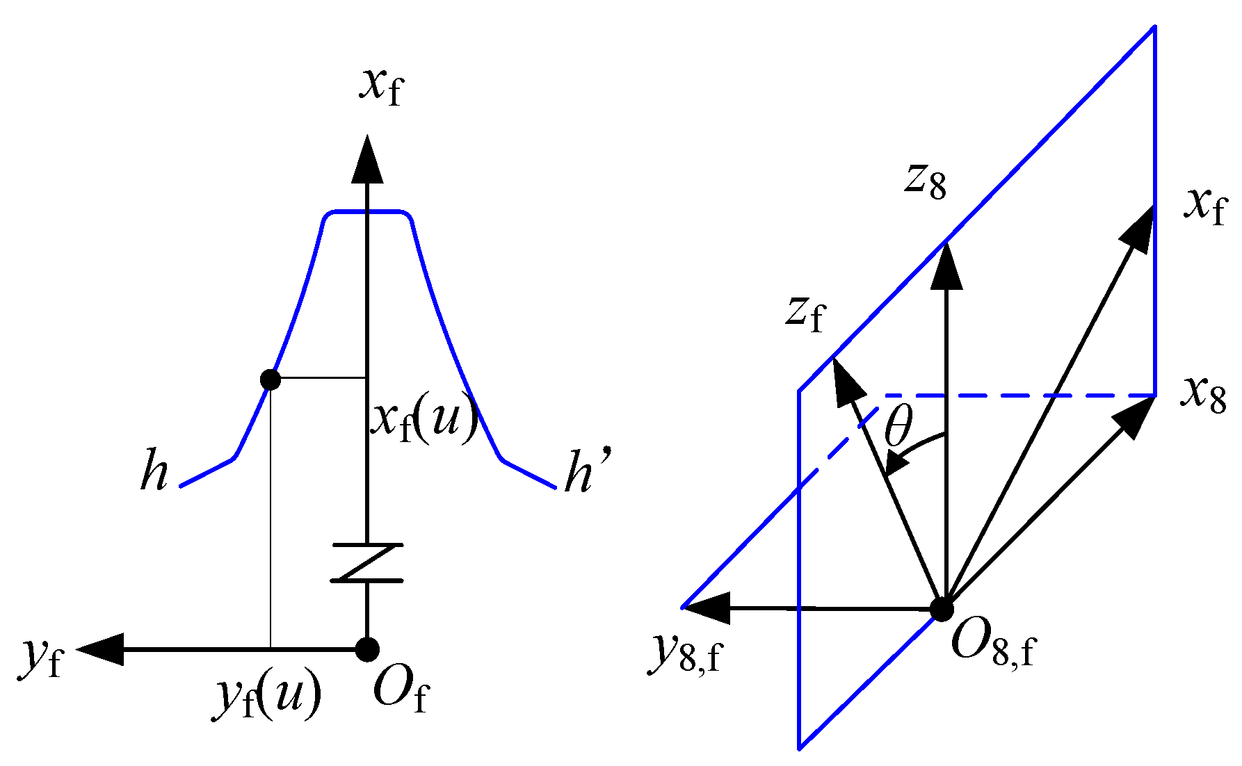
2.3. Tooth Surface Modeling of Gear Profile Grinding

To investigate the effect of assembly errors on ground tooth surface deviations, the dressing errors of the grinding wheel are ignored here. The final tooth surface of gear profile grinding is the envelope surface of a single-parameter surface family r 2 ( u , θ ; t ) , which can be solved as the following steps. First, the contact conditions between the surface family and the envelope surface are established. Then, the common points of tangential contact between the surface family and the envelope surface are calculated according to the above contact conditions. Finally, the envelope surface can be obtained by extracting these points. Therefore, the homogeneous transformation matrix T 8 2 ( t ) in Equation (1) is rewritten into the combination of rotation transformation matrix R ( t ) and translation vector p ( t ) ; thus, Equation (1) is changed into the following:
r 2 ( u , θ ; t ) = R 8 2 ( t ) r 8 ( u , θ ) + p 8 2 ( t )
Then, according to the Spatial Engagement Principle, the contact conditions between the surface family and the envelope surface should meet the following conditions:
( r 2 u , r 2 θ , r 2 t ) = 0
As a result, the envelope surface of the grinding wheel surface family can be obtained as follows:
G ( u , t ) = r 2 ( u , θ ( u , t ) ; t )

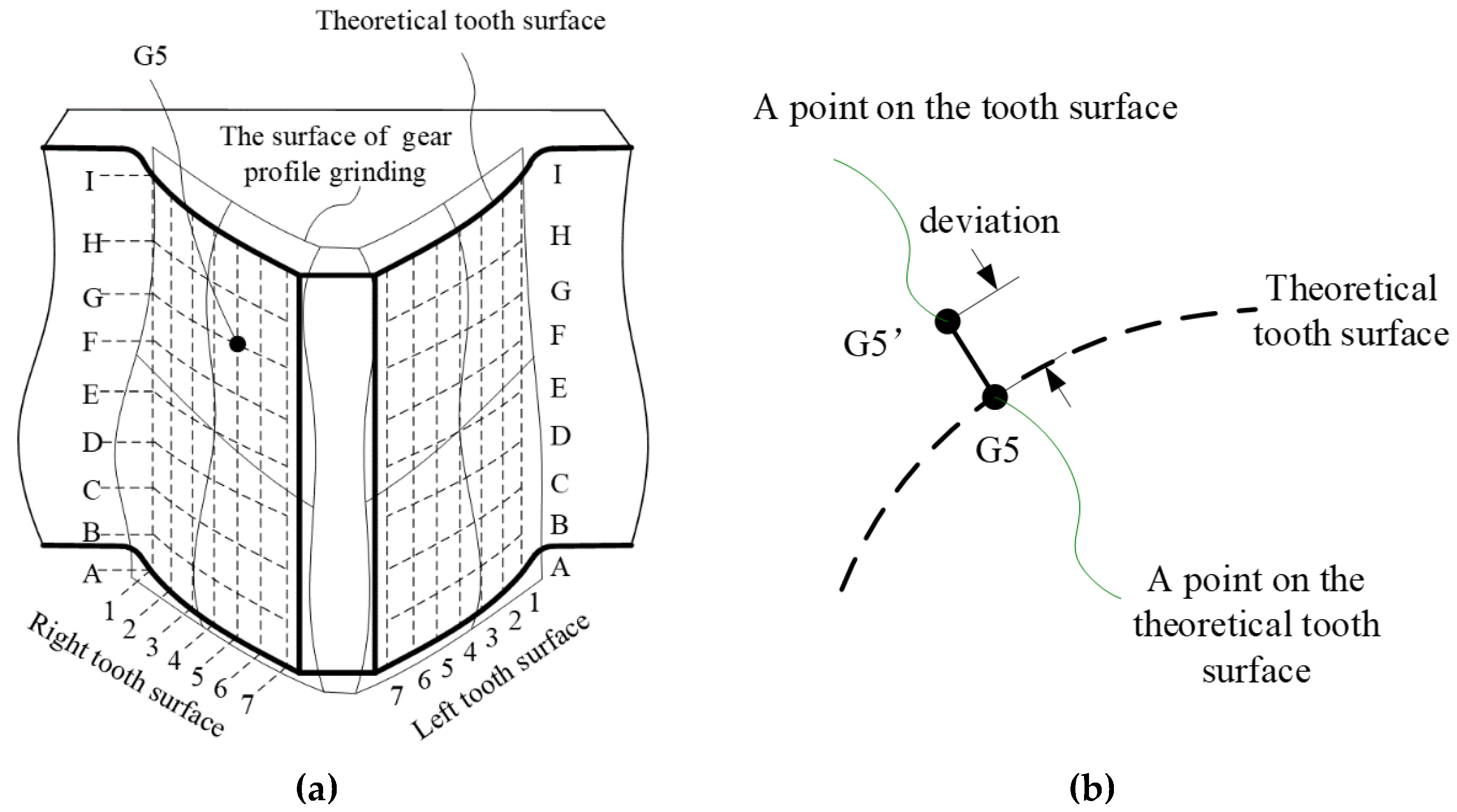
3. Evaluation of Tooth Surface Deviations in Gear Profile Grinding

To evaluate the effect of assembly errors of grinding system on ground tooth surface deviations, it is necessary to evaluate the error of the solved envelope surface. In Figure 5a, there are a series of dotted grids on the theoretical tooth surface, which intersect to form many grid points. Each grid point is represented by a letter and a number. The longitudinal curve formed by a series of grid points with the same number and different letters on the same tooth surface is called the tooth trace curve. The transverse curve formed by a series of grid points with the same letter and different numbers on the same tooth surface is called the tooth profile curve. At present, gear evaluation standards (ISO:1328-1:2013, GB/T 10095.1-2008) are based on tooth profile curve and tooth trace curve, so the errors of tooth profile curve and tooth trace curve must be calculated to evaluate the ground tooth surface deviations. In Figure 5a, The mesh composed of a series of tooth profile curves and tooth trace curves is called the topological mesh. The errors between the envelope tooth surface and the theoretical tooth surface at all grid points are called the ground tooth surface deviations.
The error of each grid point is illustrated in Figure 5b. A perpendicular line was made to the theoretical tooth surface from the discrete point on the envelope surface. Then, the corresponding point on the theoretical tooth surface was obtained. The error between the above two points is the deviation of a point on the tooth surface of gear profile grinding. All of these errors were fitted and interpolated to obtain the deviations in the ground tooth surface. According to this method, tooth profile deviation, tooth profile slope deviation, helix shape deviation, helix inclination deviation, and tooth thickness deviation of gears can be calculated and the precision grade of the gear can be evaluated. The effect of the 15 assembly errors listed in Table 1 on the ground tooth surface deviations can be analyzed based on the above method. The evaluation process is illustrated in Figure 6. There are three main steps. First, the theoretical profile r f ( u ) and coordinate transformation matrix T 8 2 ( t ) are calculated. Then, the contact equation θ = θ ( u , t ) is calculated, and the result is substituted into the surface family to obtain the ground envelope surface r 2 ( u , θ ( u , t ) ; t ) . Finally, the deviations in profile ground tooth surface can be evaluated.
In Figure 6, three cycles—A, B, and C—were included in the evaluation flow. Cycle A is when the coordinate transformation matrix T 8 2 ( t ) is determined, the contact equation is calculated for each point (different parameter u) on the grinding wheel profile, and a series of contact points are obtained. Cycle B includes cycle A, and contact lines are obtained at different moments in the grinding process and are the envelope surface formed by grinding. Cycle C includes cycle C, and its function is to set reasonable error values for different error terms, so different ground tooth surfaces are obtained and the deviation evaluation of each ground tooth surface is performed.

4. Calculation Analysis and Error Distribution

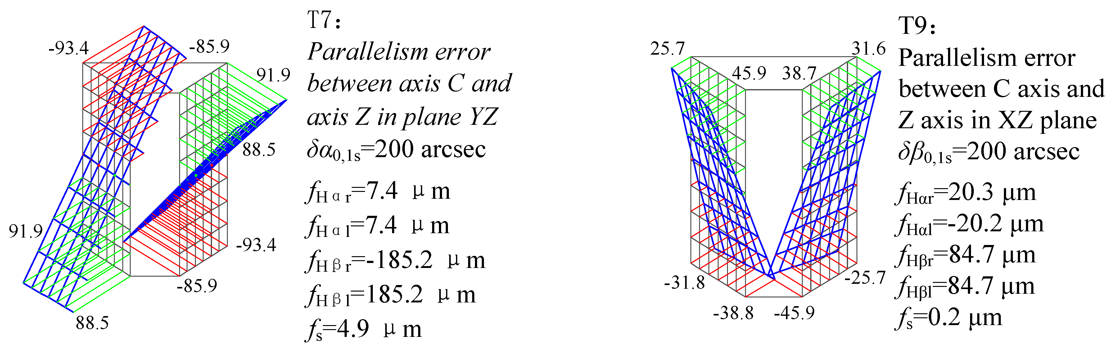
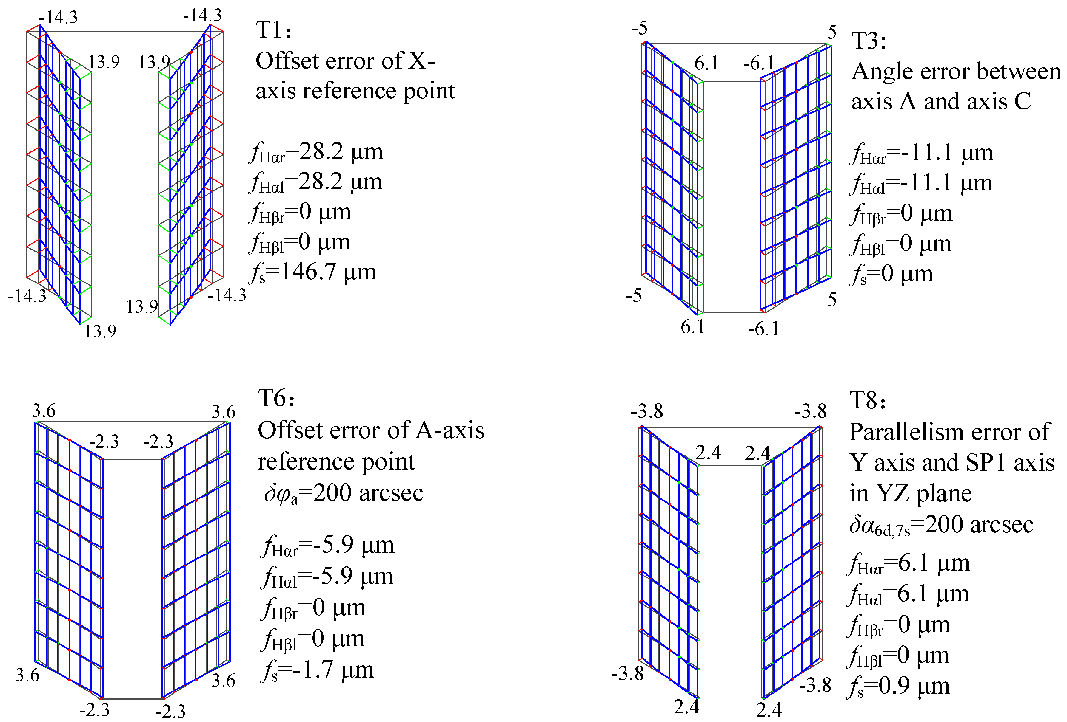
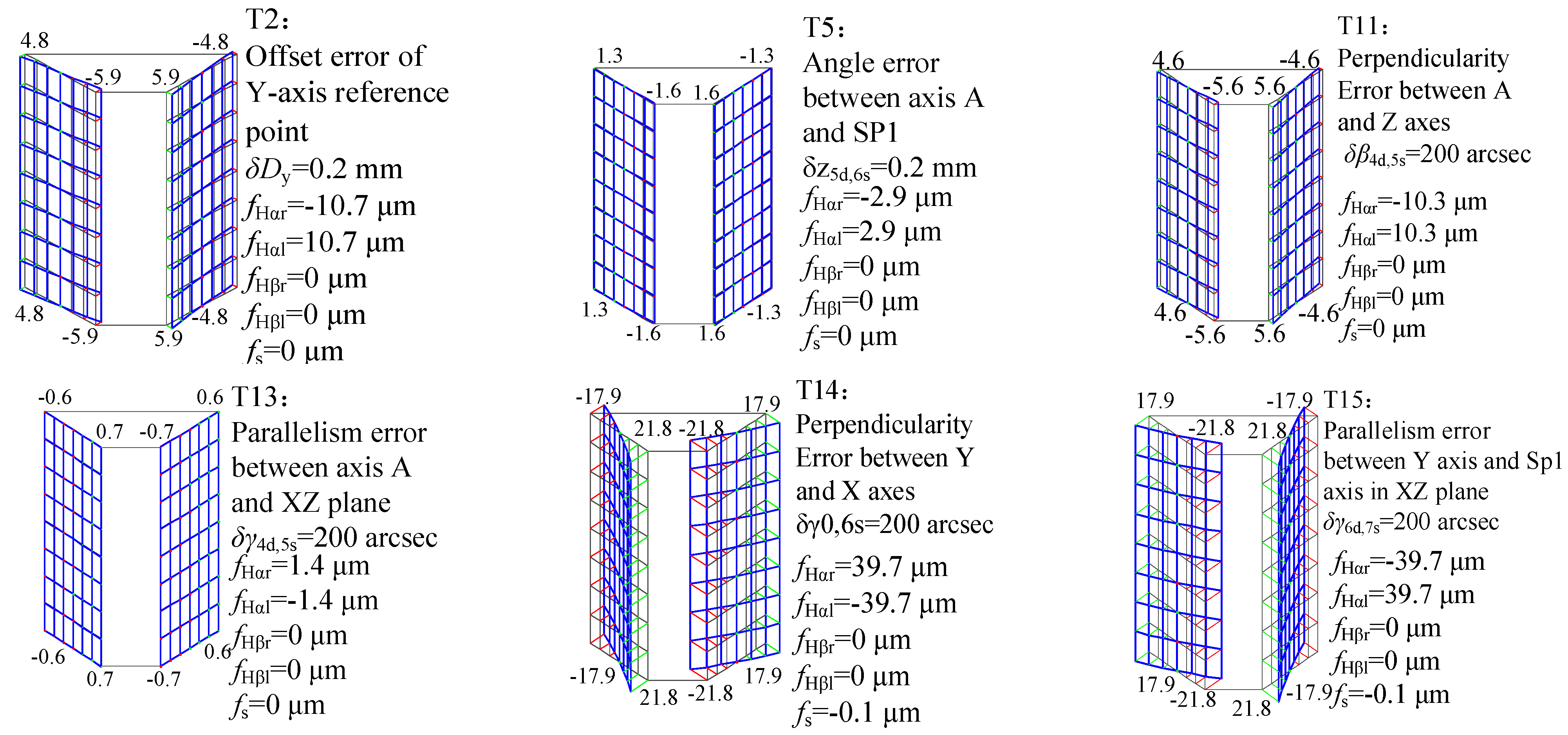
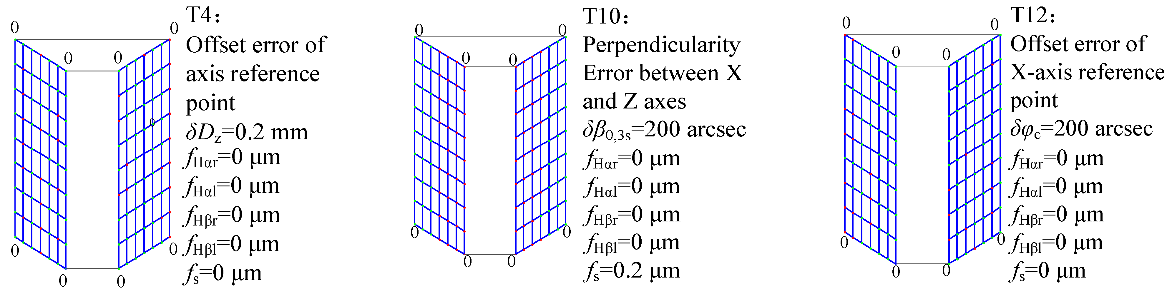
4.1. Single Value Calculation and Analysis

For a gear profile grinding, the related parameters of gear and grinding wheel are shown in Table 3. According to the flow shown in Figure 6, deviations in the ground tooth surface resulting from each error term in Table 1 are analyzed. The value of the length error term was set to 0.2 mm, and the value of the angle error term was set to 200 arcsec. Deviations in the tooth surface corresponding to each error term are shown in Figure 7, Figure 8, Figure 9 and Figure 10. f H α l and f H α r represent the maximum inclination deviation of the tooth profile in the left and right tooth surfaces, respectively. f H β l and f H β r represent the maximum deviation of helix inclination in the left and right tooth surfaces, respectively. f S represents the tooth thickness deviation corresponding to the center point of the tooth surface. In addition, the tooth profile shape deviation and helix shape deviation produced by 15 error terms were close to 0.
More characteristics were found by further analysis. (1) The deviation value of ground tooth surfaces produced by a single error term is the same on the left and right tooth surfaces. However, some deviation directions are the same, and others are opposite. (2) Among the 15 error terms, only T7 and T9 have significant effects on the helical slop deviation. (3) T1, T2, T3, T5, T6, T8, T11, T13, T14, and T15 have effects on the profile slop deviation. As shown in Figure 8, T1, T3, T6, and T8 have the same effect on the left and right tooth surfaces, while others have opposite effects on the left and right tooth surfaces, as shown in Figure 9. (4) T6 is the offset error of the reference point of axis A, which can be regarded as the angle error of the wheel before gear grinding. When the angle error is 200 arcsec, the deviation in ground tooth surface is only about 6 μm. Generally, the angle error is less than 200 arcsec, so T6 has little effect on the precision of gear grinding. (5) As shown in Figure 10, T4, T10, and T12 should also to be controlled, even though they do not produce any deviations in tooth surface, because the machining allowance of the left and right tooth surfaces are affected by them. (6) T1 has a significant effect on tooth thickness deviation, while other error terms have little influence on tooth thickness deviation.

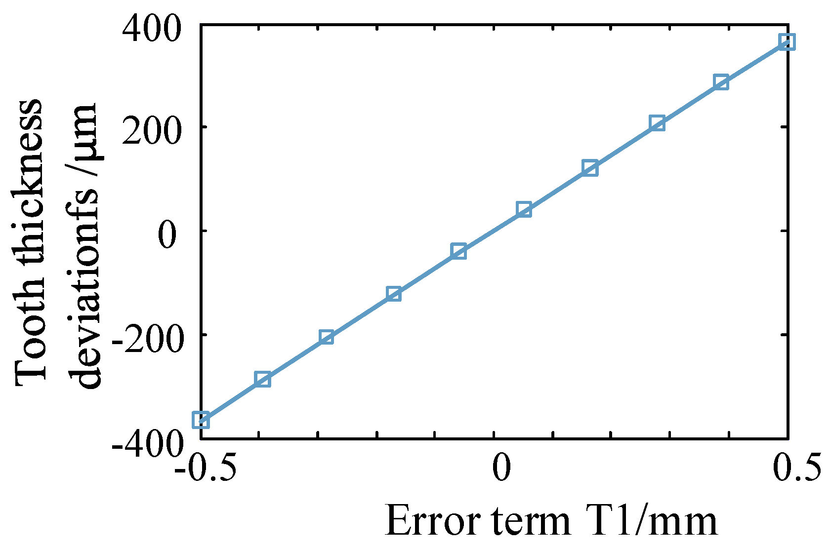
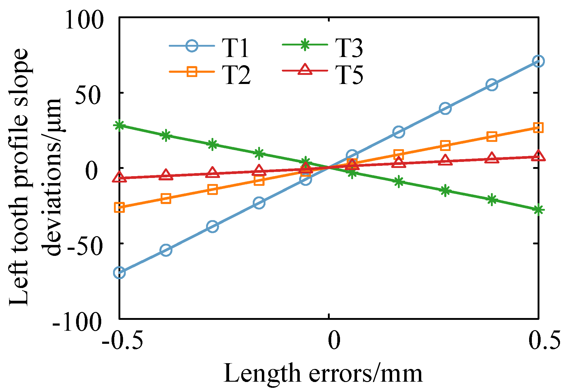
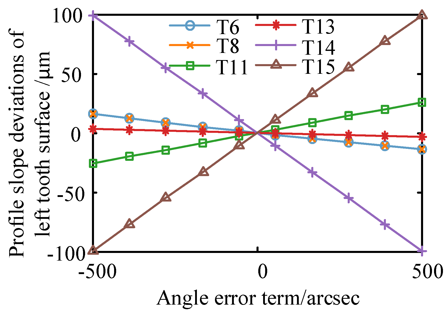
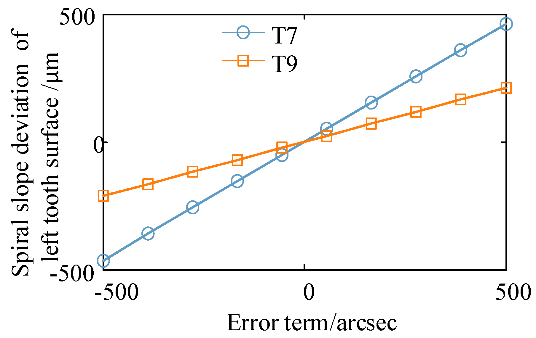
4.2. Multi-Value Computation and Analysis

According to the above analysis, tooth thickness deviation is affected by T1; tooth profile slop deviation is affected by T1, T2, T3, T5, T6, T8, T11, T13, T14, and T15; and helical slop deviation is affected by T7 and T9. From Figure 11, it can be seen that there is a linear relationship between T1 and tooth thickness deviation, and helical slop deviation also changes linearly when T7 and T9 change. From Figure 12 and Figure 13, it can be seen that there is a linear relationship between error items of T1, T2, T3, T5, T6, T8, T11, T13, T14, and T15 and tooth profile slop deviation in the range of specified values. Among these error items, the tooth profile slop deviation is greatly affected by T1, T2, T3, T14, T15, and T11. The spiral slop deviation is also changed linearly with the varying of T7 and T9, as shown in Figure 14. The above analysis results show that deviations in ground tooth surface are cumulatively increased under the combined action of many assembly errors. Excessively tightening every assembly error leads to a sharp rise in accuracy of assembly parts and difficulty of assembly operations. Therefore, it is better to optimally distribute assembly errors under the limitation of deviations in ground tooth surface.

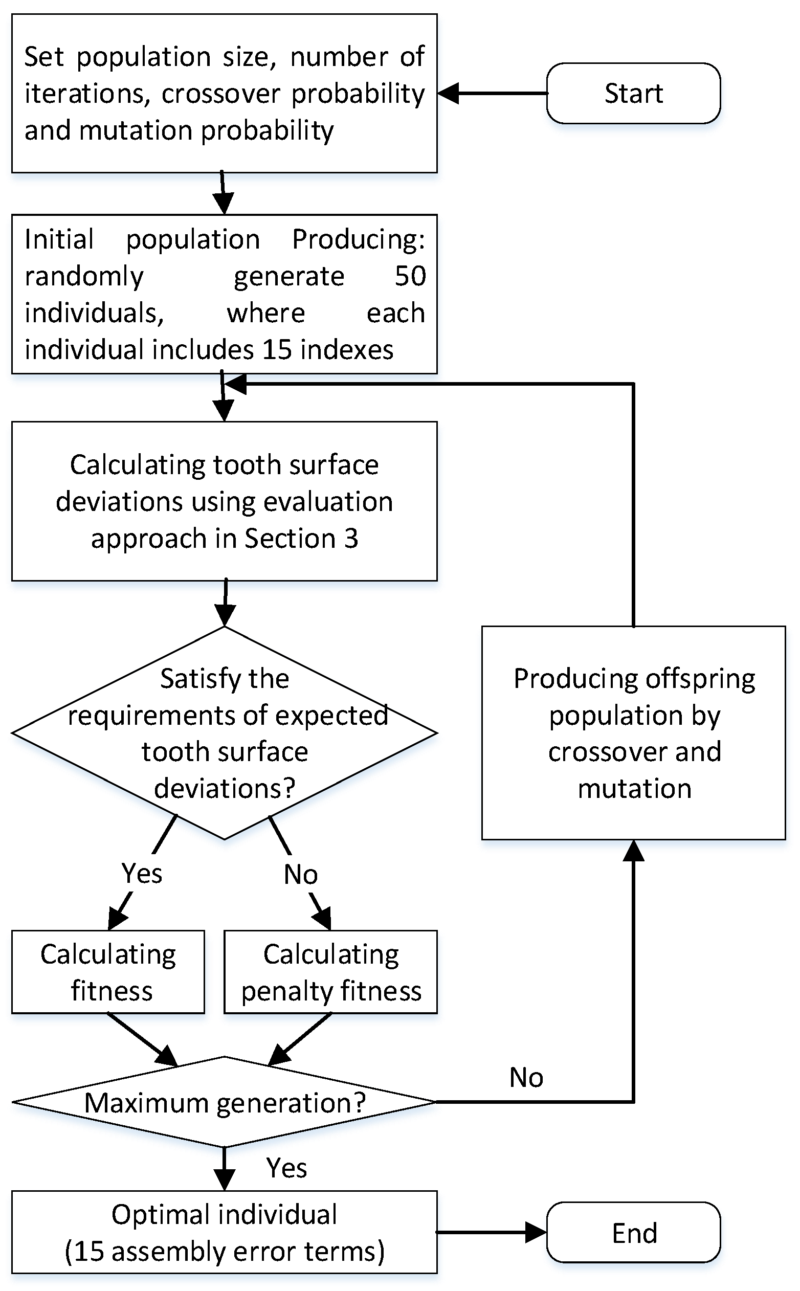
4.3. Optimized Distribution of Assembly Errors

Based on the analysis mentioned above, one error term affects several tooth surface deviations, and one tooth surface deviation may be affected by several error terms. From an empirical point of view, to ensure ground tooth surface deviations, assembly error terms of profile grinding machines should be as small as possible. However, smaller assembly errors are bound to require higher accuracy of assembly parts. Excessively high accuracy is difficult to manufacture, and the machining cost will increase sharply. Furthermore, among these error terms, some have the same effect on certain tooth surface deviations, while others have opposite effects on the certain tooth surface deviation. Therefore, a certain tooth surface deviation may be eliminated by a reasonable combination of some bigger error terms, which indicates the necessity for optimized distribution of assembly errors. In the meantime, bigger allowable assembly errors are beneficial for assembly operations of profile grinding machines.
The maximization of assembly error terms is the first objective for the present optimization problem. Considering the convenience of assembly operations, each assembly error should be relatively harmonious. The minimization of the disparity of assembly error terms is determined as the second objective. Constraint conditions are the expected tooth surface deviations and the allowable range of each assembly error term. The two objective functions are expressed as Equations (7) and (8). The weighted coefficients of the two functions are c 1 = 0.5 , c 2 = 0.5 , respectively.
f 1 ( T i ) = min 0 15 1 T i ( i = 1 , 2 , 3 , , 15 )
f 2 ( T i ) = min ( max { T i } min { T i } ) ( i = 1 , 2 , 3 , , 15 )
where T i represents the value of the i th error term.
According to the fourth grade accuracy of gears in ISO:1328-1:2013, the constraint conditions are expressed as Equation (9).
6 . 0     f s   12 . 0   6 . 5     f H α l   13 . 0   5 . 0     f H β l   12 . 0  
EI T i     T i   ES T i   ( i = 1 , 2 , 15 )
where the tooth surface deviations were calculated from the evaluation approach in Section 3 and the allowable range of each assembly error term can be obtained from Ref. [28].
The commonly used methods for optimization problems include mathematical methods (gradient descent and conjugate gradient) and heuristic methods (simulated anneal ing algorithm and genetic algorithm). The genetic algorithm (GA) is a heuristic optimization method mimicking the principles of natural genetics and natural selection in search and optimization procedures. The GA hopes to converge on a better solution by beginning with a set of potential solution, changing them through several generations. The solution of an optimization problem with the GA algorithm begins with a set of potential solution that is known as chromosomes. The entire set of these chromosomes comprises populations that are randomly selected. The entire set of these chromosomes evolve during several generations or iterations. The GA is suitable for optimization with complicated constraints and is widely used in many fields for optimizing machining parameters [29]. Using the GA, a strategy for selecting assembly errors is formulated, and the evaluation approach in Section 3 is embedded into the GA to calculate the tooth surface deviation. In order to cope with the multi-object optimization issue, the fitness function is established by the penalty function method, combining object function and constraint condition. Over successive generations, the population evolves toward an optimal solution. The flowchart for selecting assembly errors is shown in Figure 15.
In the current study, the GA was implemented using the MATLAB programming platform, in which the crossover probability was 0.98, the mutation probability was 0.05, the number of iterations was 500, and the population size was 50. The optimization results are shown in Table 4.

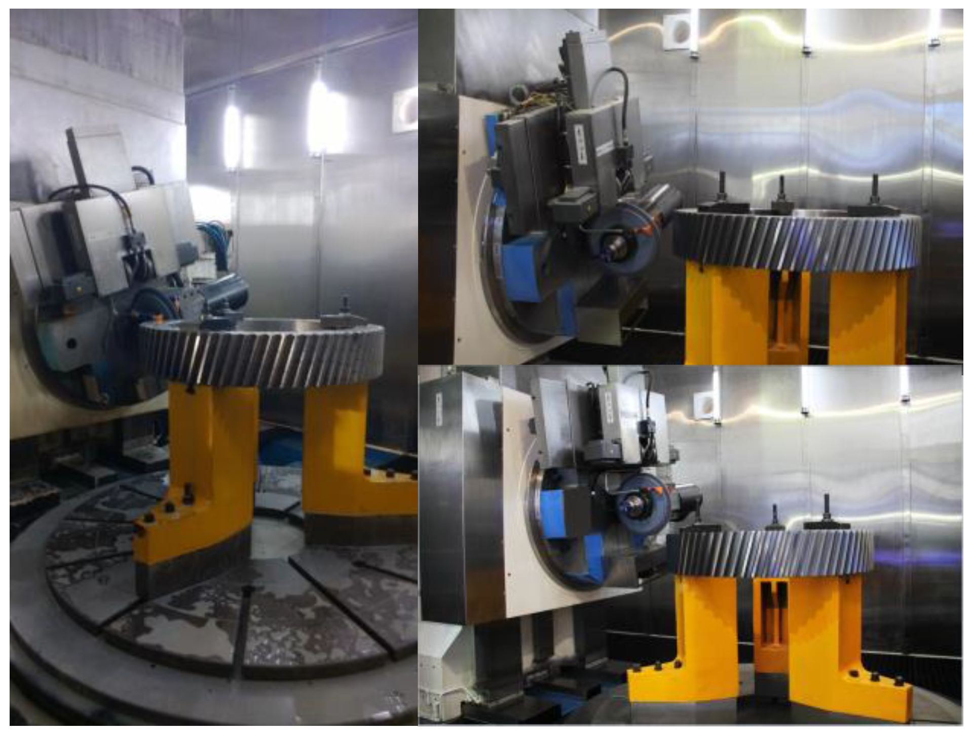
4.4. Gear Profile Grinding Test

To verify the effect of the proposed optimization method of assembly error terms, a large-scale CNC gear profile grinding machine was optimized by Nanjing Gongda CNC Technology Co., Ltd. based on the optimization results. As well known, a high level of investment is required to have a large machine tool in the lab, which is a limiting factor. Therefore, most of the advances in the field of large machine tools are supported by the industry. Two SKMC-1200W/08 CNC gear profile grinding machines were assembled. All of the materials and components used in the two machines were identical, while the assembly errors shown in Table 4 were adjusted to different values intentionally. The empirical values of assembly errors were conducted on the one machine, and the optimization values were conducted on the other machine. Among the empirical values of assembly errors, the length error was 0.02 mm, and the angle error was 0.2°, which was approximately equal to 12.5 arcsec. In order to ensure the measurement accuracy, the API laser tracker, widely applied in the assembling of aircrafts, ships, etc., was used to measure the length error and angle error of large grinding machines. Its measuring accuracy for length error was 5 μm and the measuring accuracy for angle error was 10″.
The gear profile grinding tests were carried out with identical machining parameters. The related parameters of gear grinding were set as the values shown in Table 3. The grinding process is illustrated in Figure 16. In order to ensure the comparability of tests, the same semi-finishing gear was ground on the two machines successively. On each profile grinding machine, one tooth was ground completely. After finishing, the gear was measured on a Wenzel CMM, and the measurement reports are shown in Table 5. Both tooth profile deviations and spiral deviations reached fourth grade accuracy in ISO:1328-1:2013. The results show that the optimized distribution of assembly errors can meet the requirements of expected tooth surface deviations. In addition, assembly operations of large machines are more difficult with respect to conventional size machines and need to be addressed. The results also provide information about which assembly error terms can be relaxed for the profile grinding machine designer or manufacturer.

5. Conclusions

This paper proposed a method to evaluate the effect of assembly errors on ground tooth deviations for large-scale CNC gear profile grinding machines. Specifically, a tooth surface model including assembly errors and an evaluation approach for tooth surface deviations are developed. This new approach has the following conclusions: (1) Among the 15 assembly errors, the tooth profile slop deviation is affected by T1, T2, T3, T5, T6, T8, T11, T13, T14, and T15. The influences of T1, T3, T6, and T8 on the left and right tooth surfaces are symmetrical, while other influences on the left and right tooth surfaces are reversely symmetric. The spiral deviations are mainly affected by T7 and T9. T7 has an inverse symmetric effect on the left and right tooth surfaces, and T9 has an antisymmetric effect on the left and right tooth surfaces. The tooth thickness deviation is greatly affected by T1. The deviations in ground tooth surfaces affected by T4, T10, and T12 are few. (2) Cases studies with error distributions and cutting experiments on large-scale CNC gear profile grinding machines verify the practicability and effectiveness of this distribution method. The results provide information about which assembly error terms can be relaxed for the profile grinding machine designer or manufacturer.

Author Contributions

Conceptualization, W.D.; methodology, H.Z.; software, W.H.; validation, H.Z. and W.H.; formal analysis, Y.L.; investigation, Y.L.; resources, H.Z.; data curation, W.H.; writing—original draft preparation, W.H.; writing—review and editing, W.D.; visualization, W.H.; supervision, W.D.; project administration, W.D.; funding acquisition, W.D. All authors have read and agreed to the published version of the manuscript.

Funding

This research was funded by the National Natural Science Foundation of China, Grant no. 51405220; Young academic leaders program of Jiangsu Qinglan Project.

Data Availability Statement

The data underlying this article will be shared upon reasonable request to the corresponding author.

Acknowledgments

The authors appreciate the contributions of Nanjing Gongda CNC Technology Co., Ltd. to this paper for its assistance in the experiments.

Conflicts of Interest

The authors declare no conflict of interest. Nanjing Gongda CNC Technology Co., Ltd. provides large-scale CNC gear profile grinding machines for experiments.

References

  1. Wegener, K.; Bleicher, F.; Krajnik, P.; Hoffmeister, H.-W.; Brecher, C. Recent developments in grinding machines. CIRP Ann.-Manuf. Technol. 2017, 66, 779–802. [Google Scholar] [CrossRef]
  2. Wang, K.; Sheng, X.; Kang, R. Volumetric error modelling, measurement, and compensation for an integrated measurement-processing machine tool. Proc. IMechE Part C J. Mech. Eng. Sci. 2010, 224, 2477–2486. [Google Scholar] [CrossRef]
  3. Heinzel, C.; Wagner, A. Fine finishing of gears with high shape accuracy. CIRP Ann.-Manuf. Technol. 2013, 62, 359–362. [Google Scholar] [CrossRef]
  4. Rowe, W.B. Principles of Modern Grinding Technology, 3rd ed.; Elsevier: Oxford, UK, 2013. [Google Scholar]
  5. Araujo, J.B.; Oliveira, J.F. Evaluation of two competing machining processes based on sustainability indicators, in leveraging technology for a sustainable world. In Proceedings of the 19th CIRP Conference on Life Cycle Engineering, Berkeley, CA, USA, 23–25 May 2012. [Google Scholar]
  6. Litvin, F.L.; Fuentes, A. Gear Geometry and Applied Theory, 2nd ed.; Cambridge University Press: Cambridge, UK, 2004. [Google Scholar]
  7. Denkena, B.; Preising, D.; Woiwode, S. Gear profile grinding with metal bonded CBN tools. Prod. Eng.-Res. Dev. 2015, 9, 73–77. [Google Scholar] [CrossRef]
  8. Fong, Z.; Chen, G. Gear flank modification using a variable lead grinding worm method on a computer numerical control gear grinding machine. J. Mech. Des. 2016, 138, 083302-1–083302-10. [Google Scholar] [CrossRef]
  9. Wu, Y.; Fan, C. Mathematical modeling for screw rotor form grinding on vertical multi-axis computerized numerical control form grinder. J. Manuf. Sci. Eng. 2013, 135, 051020-1–051020-13. [Google Scholar] [CrossRef]
  10. Chen, G.; Mei, X.; Li, H. Geometric error modeling and compensation for large-scale grinding machine tools with multi-axes. Int. J. Adv. Manuf. Technol. 2013, 69, 2583–2592. [Google Scholar] [CrossRef]
  11. Zhou, B.; Wang, S.; Fang, C.; Sun, S.; Dai, H. Geometric error modeling and compensation for five-axis CNC gear profile grinding machine tools. Int. J. Adv. Manuf. Technol. 2017, 92, 2639–2652. [Google Scholar] [CrossRef]
  12. Wang, S.; Zhou, B.; Fang, C.; Sun, S. Research on thermal deformation of large CNC gear profile grinding machine tools. Int. J. Adv. Manuf. Technol. 2017, 91, 577–587. [Google Scholar] [CrossRef]
  13. Yang, H.; Huang, X.; Guo, E. Analysis and compensation for pitch error in forming manufacturing big gears. Modul. Mach. Tool Autom. Manuf. Tech. 2018, 10, 59–63. [Google Scholar]
  14. Zhang, H.; Fang, C.; Guo, E.; Huang, X. Accurate lead modification of CNC gear profile grinding based on five-axis motions optimization. Comput. Integr. Manuf. Syst. 2014, 20, 3058–3065. [Google Scholar]
  15. Guo, E.; Huang, X.-D.; Fang, C.-G.; Yuan, H. Contact lines optimization method for improving tooth-trace modification accuracy of form grinding. Comput. Integr. Manuf. Syst. 2014, 20, 134–141. [Google Scholar]
  16. Ding, G.; Zhang, S.; Zhao, D.; Zhao, D. Interference study of gear form grinding based on induced normal curvature. Chin. J. Mech. Eng. 2016, 52, 197–204. [Google Scholar] [CrossRef]
  17. Li, T.; Yan, P.; Yu, G.; Ji, W. Solving the problem of interference of forming grinding wheel based on MATLAB. Tool Eng. 2021, 55, 101–104. [Google Scholar]
  18. Ding, S.; Huang, X.; Yu, C.; Wang, W. Actual inverse kinematics for location error compensation of five-axis machine tool. Comput. Integr. Manuf. Syst. 2021, 27, 1300–1308. [Google Scholar]
  19. Zhao, F.; Mei, X.; Jiang, G.; Tao, T.; Shi, J. Molding and characters analysis error of numerical control machine tool. J. Shanghai Jiaotong Univ. 2013, 47, 703–708. [Google Scholar]
  20. Lee, R.S.; Lin, Y.H. Applying bidirectional kinematics to assembly error analysis for five-axis machine tools with general orthogonal configuration. Int. J. Adv. Manuf. Technol. 2012, 62, 1261–1272. [Google Scholar] [CrossRef]
  21. Xia, C.; Wang, S.; Sun, S.; Lin, X.; Huang, X. Geometric error to tooth surface error model and identification of crucial errors in five-axis CNC gear profile grinding machines. Comput. Integr. Manuf. Syst. 2020, 26, 1191–1201. [Google Scholar]
  22. Zhao, W.; Zhang, X.; Lv, D.; Zhang, J. Technical status and strategies for domestic CNC machine tools. Aeronaut. Manuf. Technol. 2016, 9, 16–22. [Google Scholar]
  23. Sun, Y.; Liu, Y.; Ran, Y.; Zhou, Q. Assembly precision prediction method of numerical control machine tools based on meta-action. Mech. Sci. Technol. Aerosp. Eng. 2017, 36, 1734–1739. [Google Scholar]
  24. Guo, J.; Li, B.; Hong, J.; Li, X. Assembly adjustment process planning of precision machine tools based on optimal estimation of variation propagation. Chin. J. Mech. Eng. 2020, 56, 172–180. [Google Scholar]
  25. Wang, Z.; Jiang, X.; Liu, W.; Shi, M.; Yang, S.; Yang, G. Precision prediction and error propagation model of remanufacturing machine tool assembly process. Comput. Integr. Manuf. Syst. 2021, 27, 1300–1308. [Google Scholar]
  26. Chen, X.; Morgan, M.N. Advances in quality and productivity in precision grinding—A review of selected research. In Proceedings of the ASME 2016 International Manufacturing Science and Engineering Conference, Blacksburg, VA, USA, 27 June–1 July 2016. [Google Scholar]
  27. Uriarte, L.; Zatarain, M.; Axinte, D.; Yagüe-Fabra, J.; Ihlenfeldt, S.; Eguia, J.; Olarra, A. Machine tools for large parts. CIRP Ann.-Manuf. Technol. 2013, 62, 731–750. [Google Scholar] [CrossRef]
  28. Hu, W.; Wang, X. Grinding Machines Part3: Profile Grinding Machines Accuracy Inspection; China Machine Press: Beijing, China, 2014. [Google Scholar]
  29. Bhoskar, T.; Kulkarni, O.K.; Kulkarni, N.K.; Patekar, S.L.; Kakandikar, G.M.; Nandedkar, V.M. Genetic algorithm and its applications to mechanical engineering: A review. Mater. Today 2015, 2, 2624–2630. [Google Scholar] [CrossRef]
Figure 1. Schematic of a large-scale CNC gear profile grinding machine.
Machines 10 00111 g001
Figure 2. Kinematic chain of the gear grinding system.
Machines 10 00111 g002
Figure 3. Assembly errors and coordinate systems of the gear grinding system: (a) coordinate system S0 to coordinate system S2, (b) coordinate system S0 to coordinate system S4d, (c) coordinate system S4d to coordinate system S5d, and (d) coordinate system S5d to coordinate system S8.
Machines 10 00111 g003
Figure 5. Deviations between the profile grinding tooth surface and the theoretical tooth surface: (a) the gear profile grinding surface and theoretical tooth surface; (b) deviation of a point on the tooth surface of gear profile grinding.
Machines 10 00111 g005
Figure 6. Evaluation flowchart of assembly errors and profile ground tooth surface deviations.
Machines 10 00111 g006
Figure 7. Deviations in tooth surface produced by assembly errors T7 and T9.
Machines 10 00111 g007
Figure 8. Deviations in tooth surface produced by assembly errors T1, T3, T6, and T8.
Machines 10 00111 g008
Figure 9. Deviations in tooth surface produced by assembly errors T2, T5, T11, T13, T14, and T15.
Machines 10 00111 g009
Figure 10. Deviations in tooth surface produced by assembly errors T4, T10, and T12.
Machines 10 00111 g010
Figure 11. Relationship between tooth thickness deviation and T1.
Machines 10 00111 g011
Figure 12. Relationship between tooth profile slope deviations and length errors.
Machines 10 00111 g012
Figure 13. Relationship between tooth profile slope deviations and angle errors.
Machines 10 00111 g013
Figure 14. Relationship between spiral slope deviations, and T7 and T9.
Machines 10 00111 g014
Figure 15. Flowchart for selecting assembly errors based on the GA.
Machines 10 00111 g015
Figure 16. The grinding process of the SKMC-1200W/08 gear profile grinding machine.
Machines 10 00111 g016
Table 1. Assembly errors of the gear grinding system.
NumberSymbolMeaningNumberSymbolMeaning
T1δDxOffset error of the X-axis reference point T9δβ0,1sParallelism error between the C axis and the Z axis in the XZ plane
T2δDyOffset error of the Y-axis reference pointT10δβ0,3sPerpendicularity error between the X and Z axes
T3δy4d,5sAngle error between the axis A and the axis CT11δβ4d,5sPerpendicularity error between the A and Z axes
T4δDzOffset error of the axis reference pointT12δφcOffset error of the X-axis reference point
T5δz5d,6sAngle error between the axis A and SP1T13δγ4d,5sParallelism error between axis A and the XZ plane
T6δφaOffset error of the A-axis reference pointT14δγ0,6sPerpendicularity error between the Y and X axes
T7δα0,1sParallelism error between the axis C and the axis Z in the plane YZT15δγ6d,7sParallelism error between the Y axis and the SP1 axis in the XZ plane
T8δα6d,7sParallelism error of the Y axis and the SP1 axis in the YZ plane
Table 2. Coordinate transformation matrix of two adjacent coordinate systems.
SymbolMatrixSymbolMatrix
T 1 d 2
T 7 d 7 s
T 8 7 d
[ 1 0 0 0 0 1 0 0 0 0 1 0 0 0 0 1 ] T 0 a ( δ β 0 , 1 s )
T 3 s 0 ( δ β 0 , 3 s )
T 4 s 3 d ( δ β 0 , 3 s )
T c b ( δ β 4 d , 5 s )
[ cos ( θ y ) 0 sin ( θ y ) 0 0 1 0 0 sin ( θ y ) 0 cos ( θ y ) 0 0 0 0 1 ]
θ y = δ β 0 , 1 s , δ β 0 , 3 s , δ β 0 , 3 s , δ β 4 d , 5 s , δ β 6 d , 7 s , respectively
T a 1 s ( δ α 0 , 1 s )
T 5 d 5 s ( φ a + δ φ a )
T e 6 d ( δ α 6 d , 7 s )
[ 1 0 0 0 0 cos ( θ x ) sin ( θ x ) 0 0 sin ( θ x ) cos ( θ x ) 0 0 0 0 1 ]
θ x = δ α 0 , 1 s , φ a + δ φ a , δ α 6 d , 7 s , respectively
T 1 s 1 d ( φ c + δ φ c )
T 5 s c ( δ γ 4 d , 5 s )
T 6 s d ( δ γ 4 d , 5 s + δ γ 0 , 6 s )
T 7 s e ( δ γ 6 d , 7 s )
[ cos ( θ z ) sin ( θ z ) 0 0 sin ( θ z ) cos ( θ z ) 0 0 0 0 1 0 0 0 0 1 ]
θ z = ( φ c + δ φ c ) , δ γ 4 d , 5 s , δ γ 4 d , 5 s + δ γ 0 , 6 s , δ γ 6 d , 7 s , respectively
T 3 d 3 s ( D x + δ D x ) [ 1 0 0 d x 0 1 0 0 0 0 1 0 0 0 0 1 ]
d x = D x + δ D x
T b 4 d ( δ y 4 d , 5 s )
T 6 d 6 s ( D y + δ D y )
[ 1 0 0 0 0 1 0 d y 0 0 1 0 0 0 0 1 ]
d y = δ y 4 d , 5 s , D y + δ D y , respectively
T 4 d 4 s ( D z + δ D z )
T d 5 d ( δ z 5 d , 6 s )
[ 1 0 0 0 0 1 0 0 0 0 1 d z 0 0 0 1 ]
d z = D z + δ D z , δ z 5 d , 6 s , respectively
Table 3. Related parameters of gear and grinding wheel.
NameSymbolUnitValueNameSymbolUnitValue
Modulemnmm14Tooth breadthBmm200
Gear numberz-74helix parameterpmm2001.3983
Pressure angleαndeg20Grinding wheel diameterdwmm380
Helix angleβdeg15Grinding tooth root diameterdfgmm1040
Modification coefficientxn-0Grinding tooth tip diameterdagmm1104
Root diameterdfmm1037.55Grinding tooth installation angleγsdeg15
Tip diameterdamm1100.55Grinding tooth center distanceDxmm710
Table 4. Assembly errors of the optimized distribution for the profile grinding system.
NumberSymbolUnitValueNumberSymbolUnitValue
T1δDxmm0.03T9δβ0,1sarcsec15
T2δDymm0.05T10δβ0,3sarcsec50
T3δy4d,5smm0.05T11δβ4d,5sarcsec10
T4δDzmm0.2T12δφcarcsec20
T5δz5d,6smm0.2T13δγ4d,5sarcsec20
T6δφaarcsec50T14δγ0,6sarcsec20
T7δα0,1sarcsec30T15δγ6d,7sarcsec20
T8δα6d,7sarcsec20
Table 5. Measurement results of the tooth profile deviations and spiral deviations.
Left Tooth SurfaceRight Tooth Surface
f/μm (Q)f/μm (Q)f/μm (Q)f/μm (Q)
7.7 (4)7.9 (4)8.2 (4)7.3 (4)
Note: the numbers in brackets are precision levels.
Publisher’s Note: MDPI stays neutral with regard to jurisdictional claims in published maps and institutional affiliations.

