Article

MFPointNet: A Point Cloud-Based Neural Network Using Selective Downsampling Layer for Machining Feature Recognition

School of Mechanical Science and Engineering, Huazhong University of Science and Technology, Wuhan 430074, China
*
Author to whom correspondence should be addressed.
Machines 2022, 10(12), 1165; https://doi.org/10.3390/machines10121165
Submission received: 17 October 2022 / Revised: 25 November 2022 / Accepted: 1 December 2022 / Published: 5 December 2022
(This article belongs to the Section Advanced Manufacturing)

Abstract

:
Machining feature recognition is a research hotspot in recent years. A point cloud is a geometry data representation format of three-dimensional (3D) models. The use of point cloud-based convolutional neural networks (CNNs) for machining feature recognition has received increasing research attention. However, these point cloud-based networks usually have large complexity size and training time. In this paper, a selective downsampling-based point neural network for machining feature recognition is proposed. Firstly, a machining feature dataset called MFDataset is constructed and contains 33 feature types. Secondly, a selective downsampling algorithm of the input points is presented, which drops out unimportant points while keeping the important ones. In single-machining feature recognition, MFPointNet is proposed by utilizing the selective downsampling of the input points. In multi-machining feature recognition, the segmentation part of the MFPointNet is adopted with the selective downsampling algorithm to segment and recognize multiple features. Compared with other point cloud-based networks, experimental results show that MFPointNet reduces the computational complexity without losing the recognition accuracy basically. MFPointNet is more robust to model complexity when more machining feature points are input to the network. Moreover, several intersecting feature models validate the segmentation performance of MFPointNet.

1. Introduction

In the realm of smart manufacturing, each product or part originates from a computer-aided design (CAD). The technologies of CAD and computer-aided manufacturing (CAM) help increase the design productivity and the process of manufacturing products. As a bridge between CAD and CAM, computer-aided process planning (CAPP) realizes the integration of CAD and CAM. However, the independent operation of the CAD and CAPP system has resulted in the inability to interconnect design information with manufacturing information [1]. Therefore, in order to realize the information transmission between CAD and CAPP, it is indispensable to recognize the machining feature from the 3D CAD model. Machining feature recognition can directly apply the processing feature information to the design of process planning, followed by obtaining the feature information from the 3D design information. It is worth noting that how to effectively recognize machining features from CAD models remains relatively immature, which is still the focus of research in academia and industry.
Machining feature recognition techniques have been developed for over thirty years. Many researchers have proposed many recognition methods. In general, these methods can be divided into two categories: traditional recognition methods [2] and deep learning-based methods [3]. The traditional recognition algorithms can be summarized as the graph-based method [4], volume decomposition-based method [5], feature hint-based method [6], rule-based method [7], semantic-based method [8], and the hybrid method [9]. In general, these methods usually only can recognize machining features in the B-rep model [10]. In addition, they suffer from poor robustness, computational complexity, and poor ability to recognize intersecting features. In recent years, researchers try to apply deep learning algorithms to machining feature recognition. Before inputting the machining feature into the CNN, we need to convert the feature into a format suitable for the network, as described by the representation vector (RV) [11]. These feature encoding methods are mainly categorized as the voxel, multi-view representation, and point cloud. In particular, the point cloud is easily accessible and widely used in 3D shape recognition. Some existing point cloud-based networks have been proposed, such as PointNet [12], PointNet++ [13], PointCNN [14], and DGCNN [15]. These point cloud methods use publicly available datasets such as ModelNet and ShapeNet to classify or segment the specific 3D shape entities. They cannot recognize and segment groups of associated geometric entities with specific shapes and properties, such as through-holes, keyways, and threads. Moreover, the input to point cloud-based network above are all the points in the 3D model, either PointNet++ for FPS downsampling [16] or DGCNN for KNN clustering [17], resulting in a large use of computational memory and an increasing CNN training time.
Motivated by the adaptive hierarchical downsampling [18] for point cloud classification, where a permutation-invariant layer called the critical points layer (CPL) reduces the input point while keeping the important points, a selective downsampling algorithm of the point cloud input is presented in this paper. In the case of single-machining feature recognition, we construct MFDataset, a publicly available machining feature dataset. It contains approximately 2000 features per category for classification. An improved CNN structure MFPointNet, utilizing the selective downsampling of the input points, is proposed to recognize the different features. In terms of multi-machining feature recognition, the segmentation part of the MFPointNet is adopted and combined with the MLP [19] to recognize those multi-machining features.
The studies of this paper make the contributions as follows: (i) MFDataset is established, which is dedicated to specific machining features. (ii) The proposed selective downsampling algorithm reduces the computational complexity without loss in the recognition accuracy basically. (iii) MFPointNet is compared with other point cloud-based networks. Experimental results demonstrate that MFPointNet strikes a balance between recognition accuracy and computational complexity.
The remainder of this paper is organized as follows. A literature review on feature recognition methods is presented in Section 2. In Section 3, the process of establishing the machining feature dataset MFDataset is described. The proposed MFPointNet is presented in Section 4, containing the classification network and segmentation network. The network training parameters and comparative experimental results are discussed in Section 5. Finally, the conclusion is shown in Section 6.

2. Literature Review

In recent years, researchers have proposed different kinds of machining feature recognition algorithms, which can be summarized as traditional recognition methods [2] and deep learning-based methods [3]. This section conducts a wide range of feature recognition methods.

2.1. Traditional Feature Recognition Methods

The traditional rule-based recognition method mainly consists of graph-based method [4], volume decomposition method [5], hint-based method [6], and the hybrid recognition method [9].
The graph-based recognition method was first presented by Joshi et al. [20] in 1988. It introduced the concept of attributed adjacency graph (AAG), which is an auxiliary shape descriptor. Gao et al. [21] proposed the extended attributed adjacency graph (EAAG), consisting of node face attributes and arched edge attributes. Yeo et al. [22] proposed a method to evaluate manufacturability after the machining features recognition from 3D CAD models. They used two test cases to demonstrate feature recognition results. Xu et al. [23] developed the generalized attributed adjacency graph (GAAG) to recognize the high-level composite machining features in detail. The graph-based methods are effective in recognizing single features. However, these methods are difficult to deal with intersecting machining features due to their concavity to represent the relationship between surfaces. Furthermore, the graph-based method tends to have inaccurate recognition.
The hint-based method was developed by abundant information as an indispensable module of a machining feature’s boundary. This kind of method generates hints based on the rules. They include topological, geometrical [24,25,26] and taxonomies [27,28]. Then these features are inferred by these hint rules [29]. Li et al. [30] presented a novel hint-based shape feature recognition approach for 3D B-rep models. Gong et al. [31] put forward a hole feature recognition method based on the hint. They completed the automatic recognition of hole features and can endow machining and manufacturing semantics for manufacturability checks. However, the hint-based method has its application limitations. It is difficult to recognize the feature hint in the case of interacting machining features.
The volume decomposition method decomposes the removal volume of stock into intermediate volumes. The machining features are presented by combining these volumes based on the predefined rules. It can be divided into convex-hull decomposition [32,33] and cell-based decomposition [34,35]. Woo et al. [36] proposed a set of machining features in a part to recognize by decomposing the delta volume. Gupta et al. [37] used volume subtraction and syntactic pattern recognition to identify machining features on a prismatic part from B-Rep data extracted from a 3D model. However, the volume decomposition method is less accurate and more computationally intensive in recognizing features.
Based on the above recognition method, many experts proposed varied hybrid machining feature recognition methods. Verma et al. [38] proposed a hybrid machining feature recognition method consisting of graphs and hints to recognize the milling features. Rameshbabu et al. [39] proposed a hybrid recognition method combining the volume decomposition method and the graph-based method to recognize machining features from a 3D model. Jong et al. [40] used the hybrid recognition method based on the graph-based method, the rule-based method, and the hint-based method to identify 3D shape features. Guo et al. [41] developed a hybrid 3D machining feature recognition method to recognize machining features, based on the graph-based method and the rule-based method. Mazin wswasi et al. [42] presented a methodology for recognizing the features of rotational parts. They extracted the geometrical and topological information of the feature, building a dataset containing 54 predefined features. Sunil et al. [43] developed a new hybrid (graph + rule-based) approach for recognizing the interacting features from B-Rep CAD models of prismatic machined parts. Although the hybrid feature recognition methods eliminate some flaws of the above method, they still suffer from low multi-machining feature recognition accuracy and high computational cost.

2.2. Deep Learning-Based Feature Recognition Methods

With the development of deep learning, researchers have tried to apply deep learning algorithms to machining feature recognition in recent years.
The voxelization-based method is to voxelize the triangular mesh model into a 3D voxel mesh, which is then input into the CNN. Zhang et al. [44] proposed FeatureNet to learn machining features from CAD models of mechanical parts. Sambit Ghadai et al. [45] presented the 3D-GradCAM framework to learn local features from a voxelized representation of a CAD model and classify its manufacturability. Ning et al. [46] studied a convolutional neural network combined with a graph-based method to recognize the machining features. The comparison results demonstrated the high recognition accuracy of convex features. Dheeraj Peddireddy et al. [47] presented a two-step machining process identification system based on a 3D CNN and transfer learning. The system showed more than 98% accuracy in identifying the manufacturability of a part. Lee et al. [48] proposed a method to reconstruct 3D CAD models containing machining features into voxels through an encoder–decoder network. The recognition accuracy of the voxel neural network is closely related to resolution size. As the voxel resolution increases, the computational cost increases linearly. This makes large-scale network training difficult.
There are also studies where machining feature recognition technology is combined with 3D CAD systems. Lee et al. [49] presented a deep learning method to recognize machining features from a 3D CAD model and detect feature areas using gradient-weighted class activation mapping. Their model can achieve a feature classification accuracy of 98.81%. Yeo et al. [50] proposed a method making integration of a 3D CAD system with a neural network using feature descriptors as input for recognizing machining features. The feature types for all test cases were recognized. Zhang et al. [51] designed an intelligent machining feature recognition method for STEP-NC-compliant manufacturing based on the artificial bee colony algorithm and back propagation neural network. It was concluded by some case studies that the method is feasible. Shi et al. [52] presented a feature recognition method using heat kernel signature for manufacturability analysis.
The multi-view representation method uses the feature multi-view images as input for recognition. Shi et al. [53] presented MsvNet, in which multiple sectional views of a model are inputted into the CNN for recognition. However, it is difficult to segment intersecting features accurately according to the shape information in an unsupervised way, since the topology information of the features might be destroyed. Motivated by an object detection algorithm named single shot multibox detector (SSD), Shi et al. [54] proposed SsdNet, where feature segmentation and recognition are carried out via supervised learning. However, these methods produce less favorable results in recognizing highly interacting features, especially when collecting training data becomes difficult. To tackle the above issue, Shi et al. [55] designed a method named RDetNet which is capable of recognizing highly interacting features with small training samples. Experiments showed the interacting feature recognition performance of RDetNet.
A point cloud is a series of data points in 3D space that contains only 3D coordinates XYZ or contains other attributes such as normal vectors. Andrew et al. [56] presented a method for the creation and labeling of point clouds from 3D CAD models for machine learning technology. Qi et al. [12] designed PointNet, which is accepted the point cloud as input directly and the model classification or part segmentation as output results. To improve the network performance, Qi et al. [13] improved a network called PointNet++ to combine the features from multiple scales. Li et al. [14] introduced a CNN architecture called PointCNN to learn the x-transformation from input clouds directly. Wang et al. [15] proposed a dynamic graph CNN for learning on point clouds, which uses the Edge-Conv to make local geometric architecture. Yao et al. [16] constructed a feature recognition approach based on the hierarchical neural network. It is demonstrated to recognize the features accurately with low computational cost. Zhang et al. [57] designed the associatively segmenting and identifying network (ASIN) based on point cloud to recognize the machining features. The ASIN can realize the machining feature segmentation, feature identification, and bottom face identification simultaneously. Jonathan et al. [58] described a machining feature recognition based on the point cloud. They used PointNet as the baseline architecture. This approach can be used to recognize 12 features, with a recognition rate of 95%.

3. Machining Feature Dataset Creation

This section first summarizes some of the relevant issues in the existing literature, which motivate the proposed method. Then, the creation process of the point cloud machining feature dataset is illustrated in detail.

3.1. Overview

As discussed in Section 2.1, the traditional feature recognition methods (Yeo et al. [22] and Sunil et al. [43]) suffer from inaccurate recognition and intensive computational cost. Moreover, they have difficulty recognizing intersecting features.
As illustrated in Section 2.2, voxel recognition methods (FeatureNet [44]) and multi-view recognition methods (MsvNet [53]) are subject to many objective experimental conditions. Point cloud data are easily accessible. Most existing point cloud-based recognition methods (PointCNN [14]) classify or segment the 3D object, rather than the machining feature. Additionally, there is a lack of dedicated feature datasets. Not only that, but the existing point cloud-based method (PointNet [12] or PointNet++ [13]) inputs are all point data, causing the network to be more computationally and parametrically intensive. Therefore, the main research of this paper is how to construct a machining feature dataset and reduce the network complexity size while ensuring the recognition accuracy. To solve these problems, an improved method is proposed in this paper.

3.2. Definition and Types of Machining Feature

Machining feature is a set of geometric shapes with certain properties and semantics in parts [59]. After reference to the machining feature specified in the ISO STEP AP224 [60] standard, we construct MFDataset by SolidWorks, containing about 66000 machining feature data.
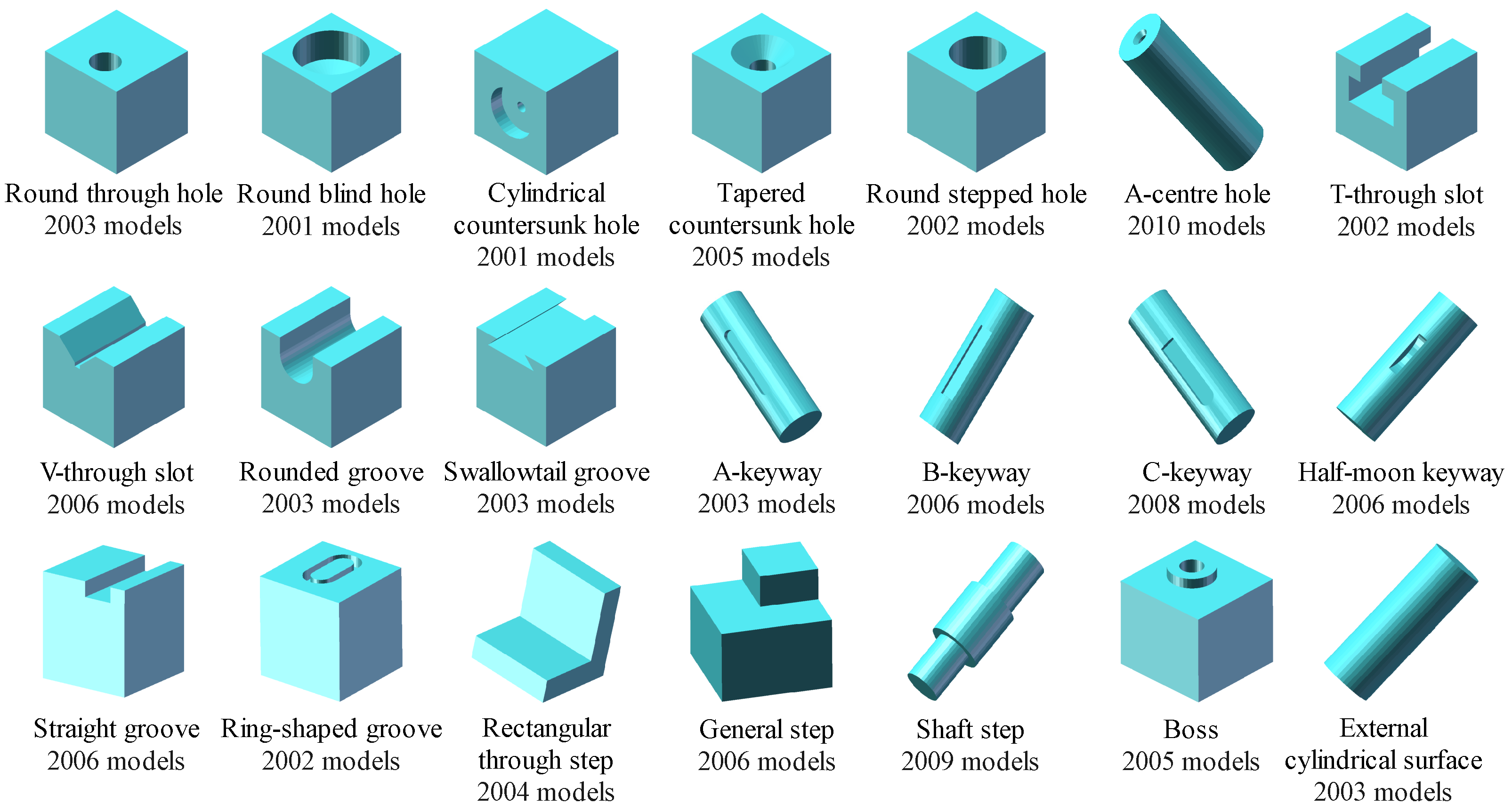
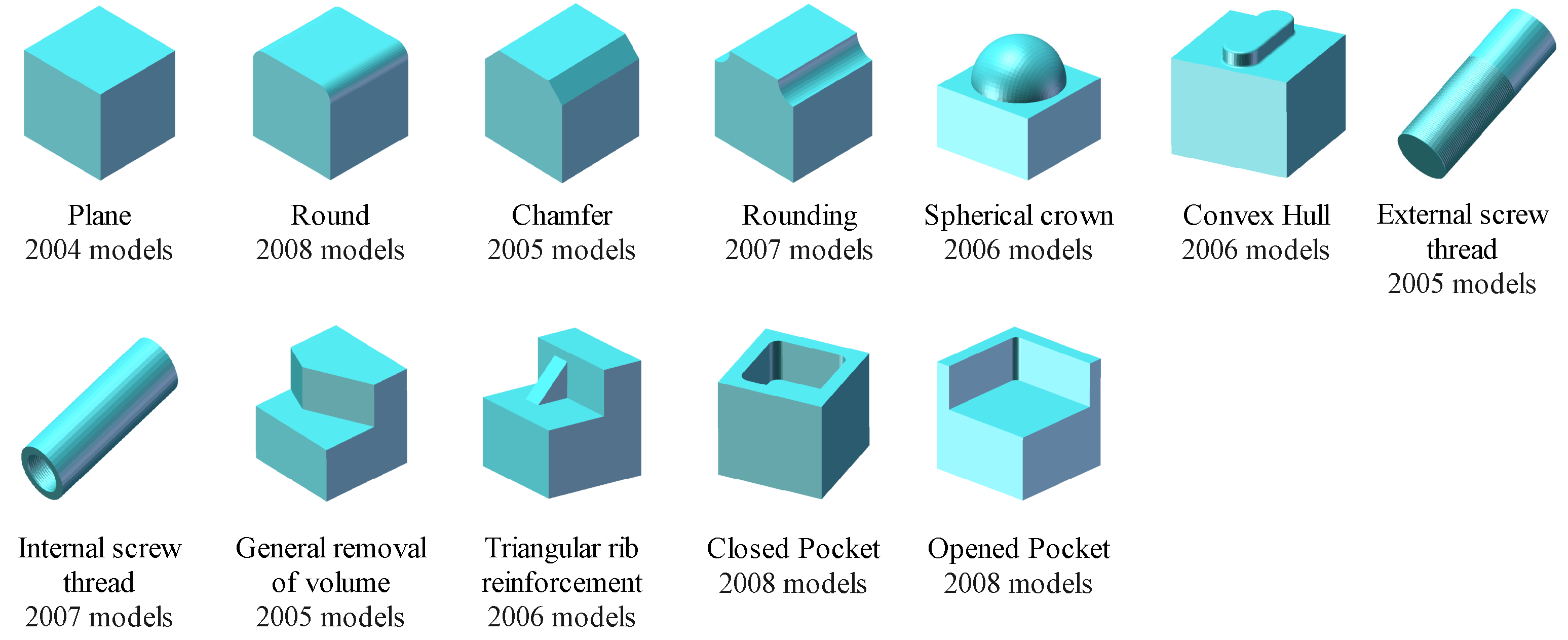
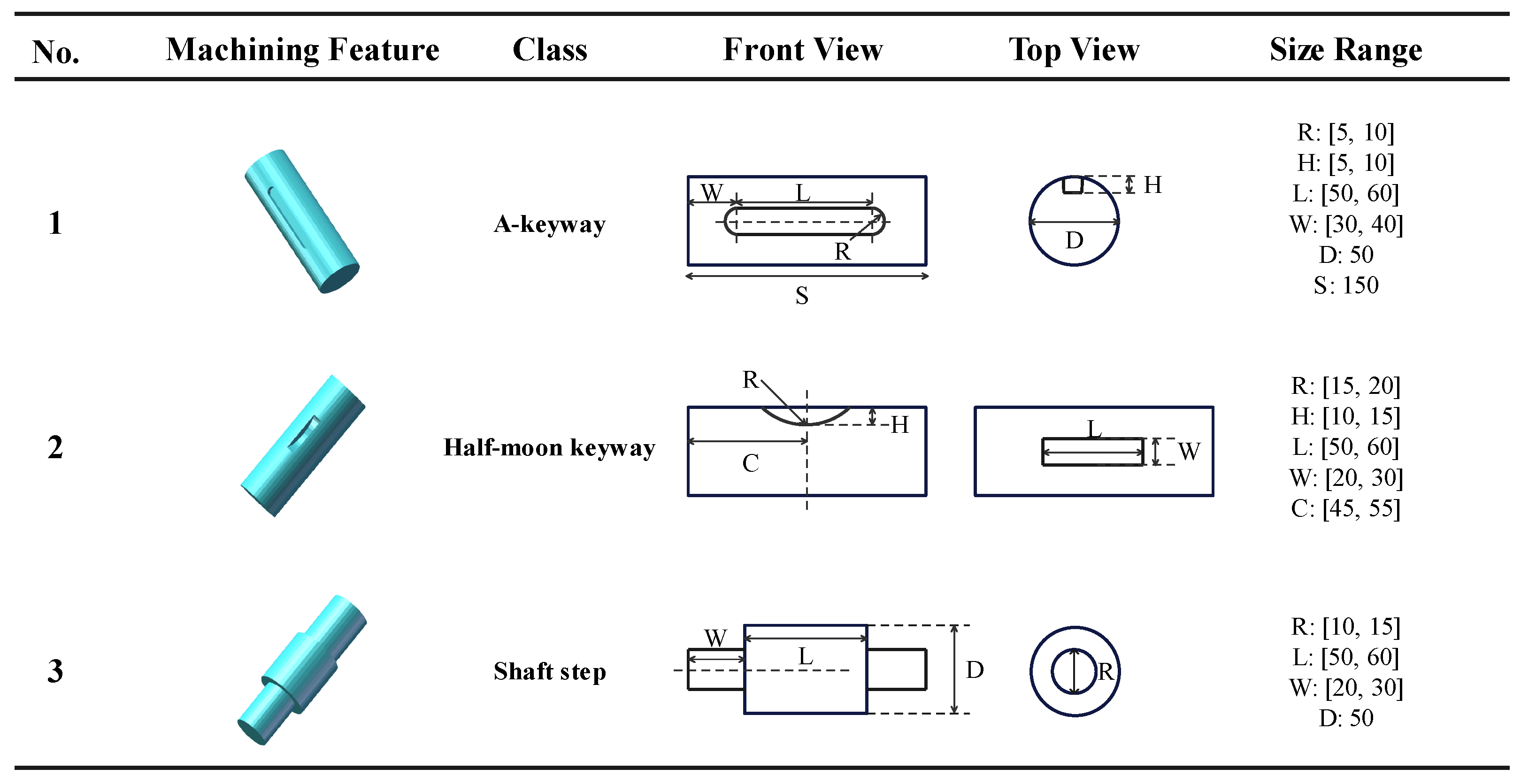
A cubic raw stock of 10 cm × 10 cm × 10 cm side length is applied to create the non-rotary feature models, as shown in Figure 1. Moreover, Figure 2 shows some rotary machining feature models, which are established by a raw cylindrical blank of 5 cm in diameter × 15 cm in height. These machining feature models are generated with random parameters in a predefined certain range. All the feature types of MFDataset are presented in Figure A1 in Appendix A. All the parameter ranges of MFDataset are presented at https://github.com/leiruoshan/MFPointNet_feature_dataset (accessed on 2 June 2022).

3.3. Point Cloud Feature Dataset

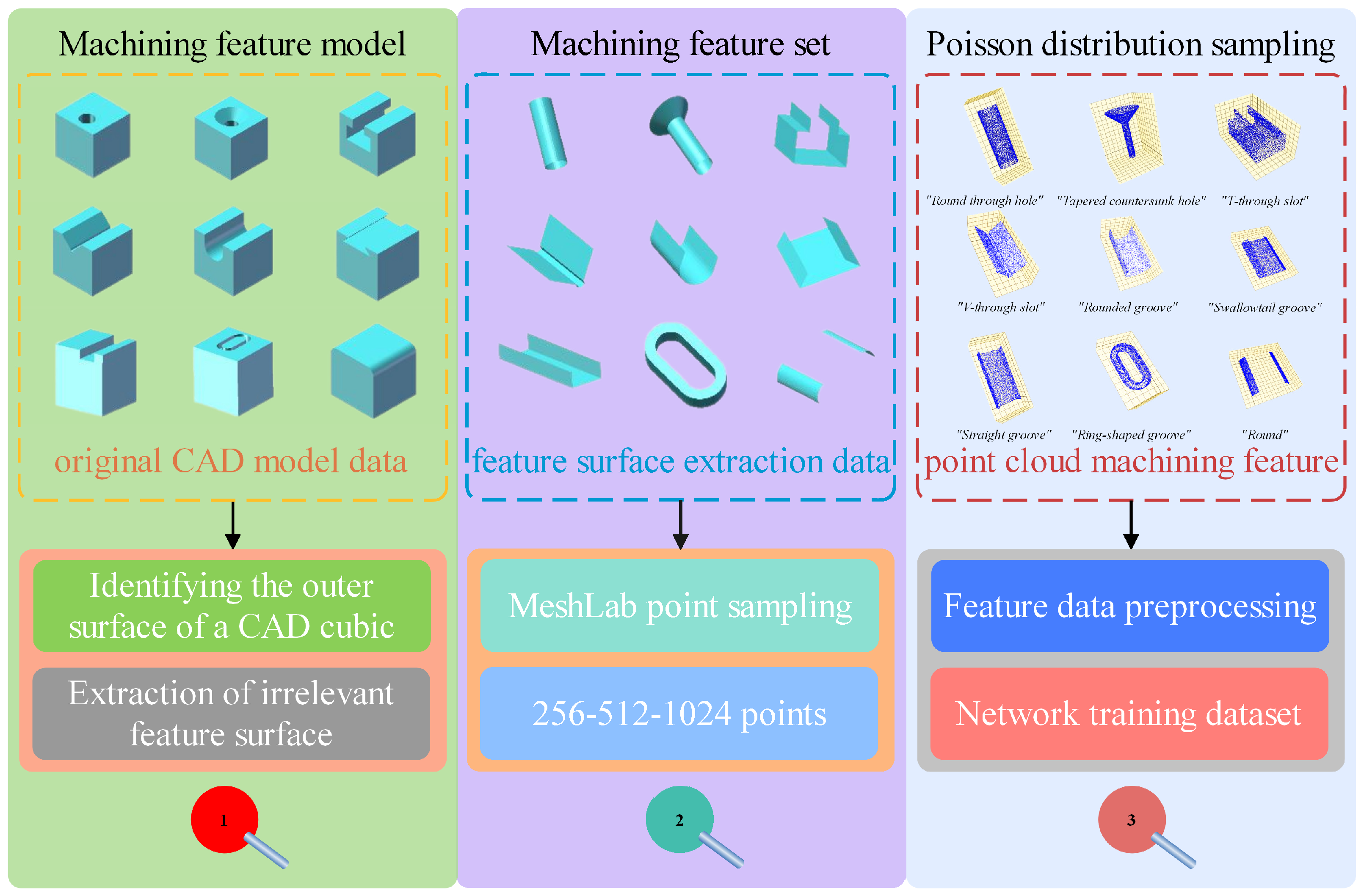
A point cloud is a representation of 3D objects in real space. Each point is determined by the three coordinate dimensions (X, Y, Z). Moreover, the point can also be expressed by (X, Y, Z, σ x , σ y , σ z ), where σ x denotes the spatial normal vector along the x-axis. For machining feature datasets in the STL format model, we need to transform it into the point cloud format which is suitable for inputting point cloud-based networks. Figure 3 illustrates the dataset conversion process. The process can be divided into three steps: (i) The machining feature surface sets non-relevant to the feature should be stripped from the original STL format model. (ii) We use the Poisson distribution sampling [61] on machining feature surface sets to get the point cloud feature models. (iii) The point cloud models are augmented through random rotation. After data pre-processing, the point cloud machining feature dataset is established.

3.3.1. Extraction of Machining Feature Surface Point Sets

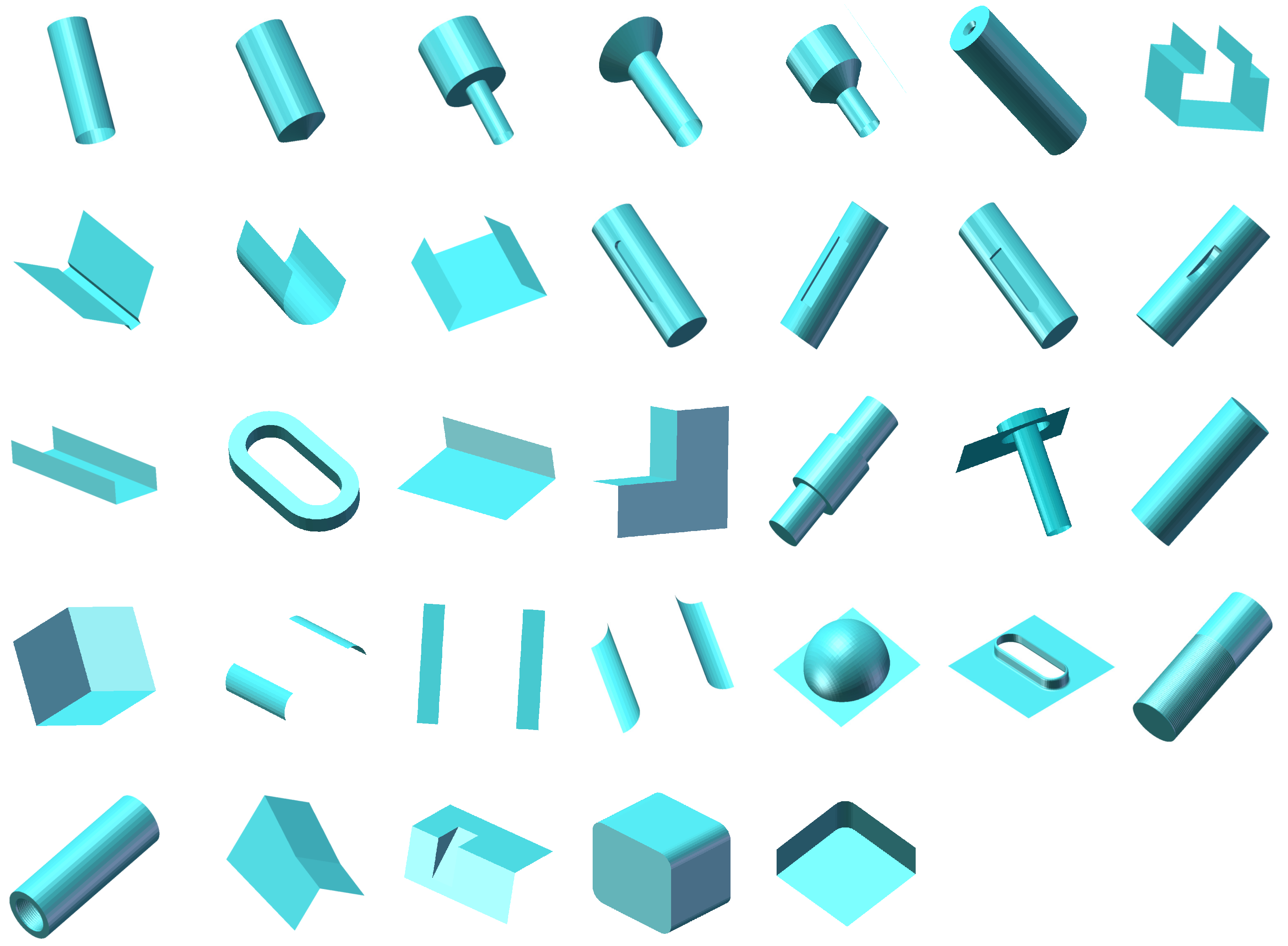
In order to reduce the impact of the cubic on the recognition accuracy, a machining feature dataset containing the surface point sets is used in this paper. The triangular faces that are not part of the features need to be removed from the original STL model. The machining feature surface point set extraction procedure is shown in Algorithm 1. All the feature surface point extraction results are shown in Figure A2 in Appendix B.
Algorithm 1 The process of machining feature surface set extraction.
  • Input: Original STL feature model with the cubic raw stock
  • Output: STL feature model after feature surface point sets extraction
  •     for ProcessSurface (document) do
  •           if select (document) == NULL then
  •                 return false;
  •           else
  •                 file += open (document);
  •                 S += pass “solid *.**”;
  •                 if S != “endsolid” then
  •                       file += normal vectors + coordinates;
  •                       if addsurfaces (normal, vertex) then
  •                            newSets += face (normal, vertex);
  •                       end if
  •                 end if
  •          end if
  • end for
  • for addsurfaces (normal, vertex) do
  •     i = 0 || i = 1 || i = 2;
  •     j = 0 || j = 1 || j = 2;
  •     if vertex[i][j] == 0 || vertex[i][j] == 10 then
  •           return true;
  •     end if
  • end for

3.3.2. Poisson-Disk Sampling

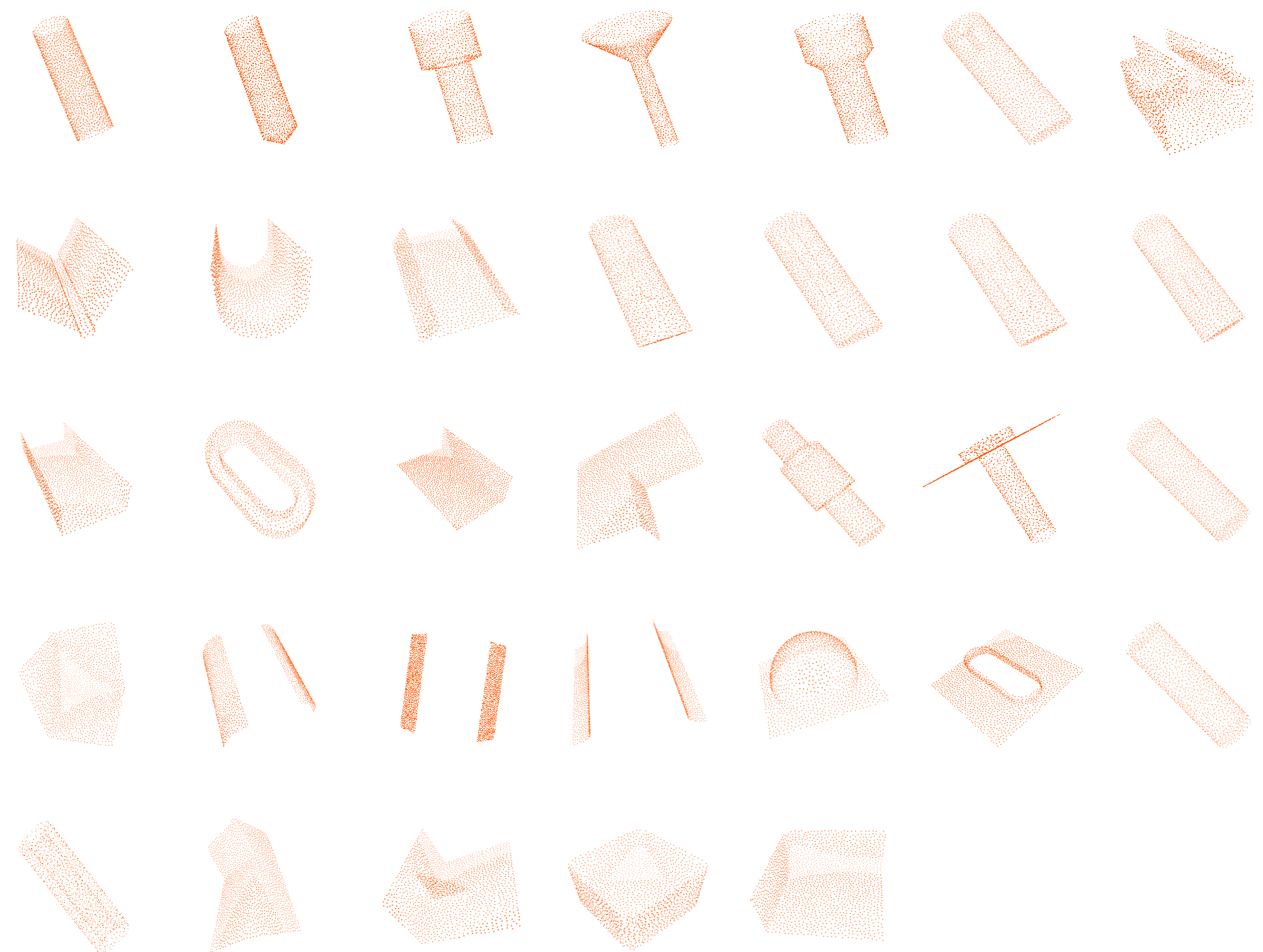
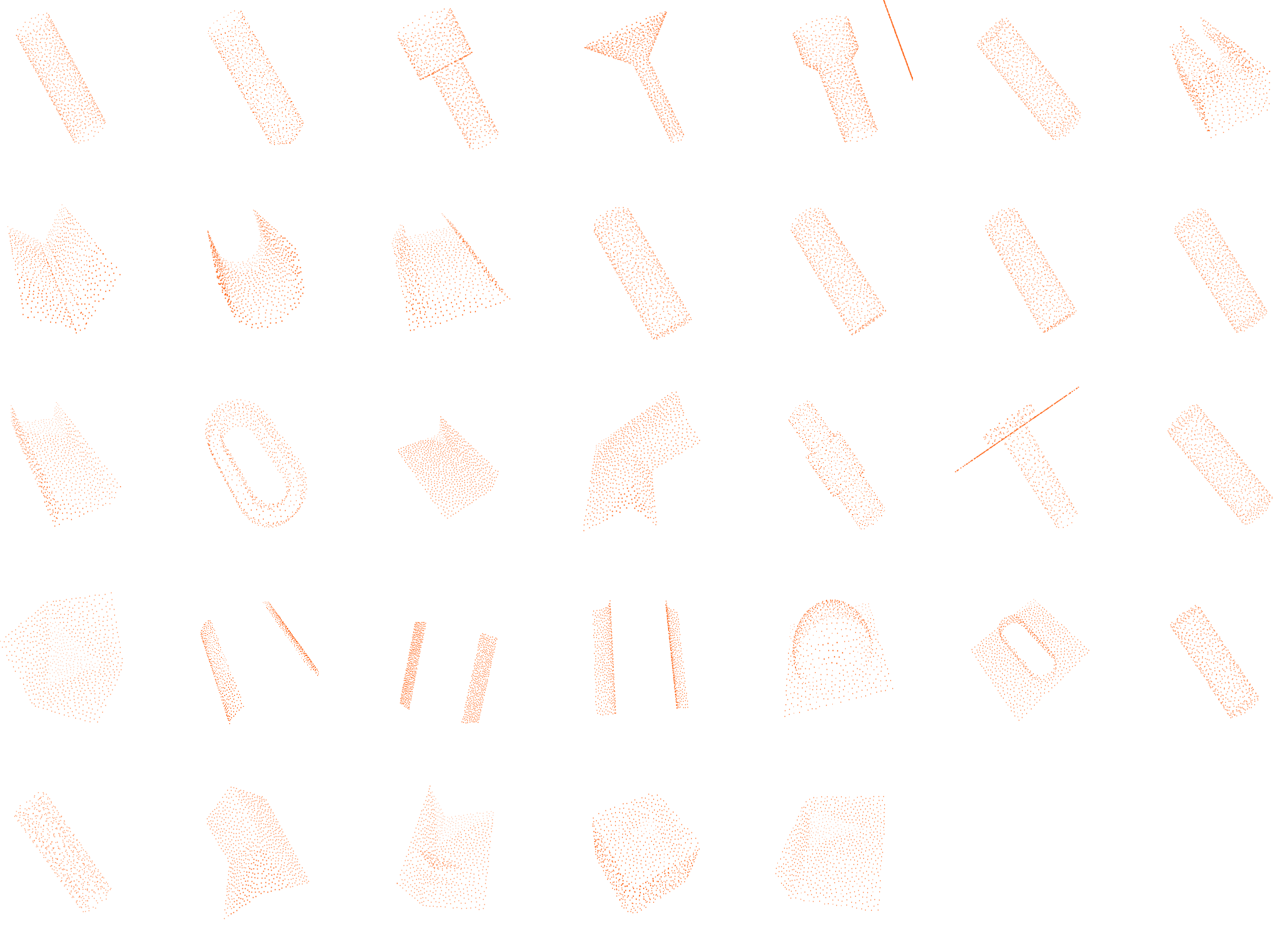
The technique of uniform sampling of the triangular grid is the key point to obtaining the feature dataset. Corsini et al. [62] presented a constrained Poisson-disk sampling algorithm to generate customized point sets. This method creates a new layer populated with a point sampling of the current meshes. Based on the Poisson-disk sampling, we use a 3D mesh processing software named Meshlab [63] to achieve the sampling from the original STL format models. For each feature type, we collect the coordinates without normal vectors by default, sampling 256 points, 512 points, and 1024 points, respectively. For the comparison experiments, we additionally collect point clouds with normal vectors for 1024 points. Some point cloud models are shown in Figure 4. The 512-point sampling model and the 256-point sampling model are shown in Figure A3 of Appendix C and Figure A4 of Appendix D, respectively.

3.3.3. Feature Data Pre-Processing

Machining features can appear in any position of a model with diversified attitudes and sizes. Even identical machining features can lead to different point cloud data due to differences in location. These create a great deal of uncertainty in feature recognition. Therefore, we need to normalize the point cloud data by offsetting the point cloud to the origin and scaling the data to [−1, 1], which can be illustrated as follows (Equations (1)–(3)):
x i + = 2 × x i m e a n ( x ) max ( x ) min ( x )
y i + = 2 × y i m e a n ( y ) max ( y ) min ( y )
z i + = 2 × z i m e a n ( z ) max ( z ) min ( z )

3.4. Multi-Machining Feature Dataset

To recognize the multi-machining feature precisely, some point cloud feature models are established. They are based on MFDataset, by a Boolean summation operation [64] of multiple single-machining features. All the multi-machining feature models are built on the cubic raw stock of 15 cm × 15 cm × 15 cm side length. The detailed information of the models is shown in Table 1. An intersecting number of features (3–8) is randomly applied to construct the feature models. When the number of features is 3 or 4, we define the models as slightly intersecting features; when the number is 5, we call them moderately intersecting features; otherwise, they are viewed as highly intersecting features.

4. MFPointNet for Machining Feature Recognition

In this section, we present the MFPointNet architecture based on the original PointNet. MFPointNet can be divided into single-machining feature classification tasks and intersecting feature segmentation tasks, as shown in Section 4.1 and Section 4.2, respectively.

4.1. Single-Machining Feature Recognition

Unlike PointNet, which inputs all points data into the network, MFPointNet only selectively inputs some more important points data into the network. Moreover, the selective downsampling layer (SDL) avoids judging the importance only based on the global maximum pooling for each feature vector in adaptive hierarchical downsampling [18] module. The description of the SDL module and MFPointNet are explained as follows.

4.1.1. The Selective Downsampling Layer (SDL)

The SDL module measures the importance of each machining feature point by the degree to which it contributes to the global average pooling feature (avg-reduced feature vector). The detail of the SDL module is shown in Figure 5. Firstly, the original network input has N feature points, each feature with dimension D, i.e., the input machining feature f is an N × D two-dimensional matrix. The average of each column of f is taken to obtain a 1 × D feature vector f a . Secondly, the first value of the machining feature points that are greater than the average value in each column are stored in the feature vector f m , and the index corresponding to each of the machining features in f m are marked down and saved in the array idx. idx represents the specific feature points that contribute to the input machining feature vector f. Thirdly, the corresponding values in f m of the duplicate indexes in idx are added up and represented by a new feature vector f c . Meanwhile, the indexes are stored in a new vector uidx after merging duplicate indexes. Fourthly, the feature points of f c are sorted in ascending order, and the corresponding indexes are sorted in order successively. suidx is used to represent the new indexes. Considering that different numbers of points during network training will result in different numbers of indexes in the suidx array, nearest neighbor resizing [65] is used to transform suidx into a new index array ruidx to ensure that the same number of machining feature points is fed into MFPointNet. Finally, the input N × D features are turned into M × D features, where M ≤ N, according to the index ruidx of the machining feature points with large contributions. By reducing the number of features from N to M, we achieve the selective downsampling of the input machining feature points.

4.1.2. The Architecture of the MFPointNet

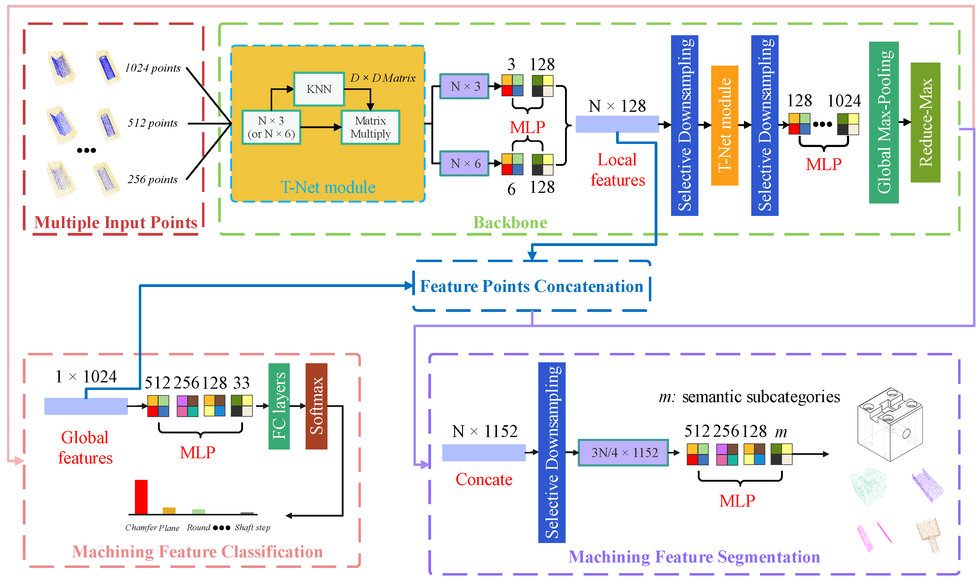
The overall architecture of the MFPointNet is shown in Figure 6. The number of input points is set to N, and the input point cloud is p R N × 3 (no normal vector) or p R N × 6 (using normal vector). The overall structure is divided into two branches: single-machining feature classification and multi-machining feature segmentation.
In the backbone, after inputting the feature points into a T-Net module, the attribute of input points remains unchanged. MLP (3, 128) or MLP (6, 128) is convolved through a two-layer perceptron network [66] to obtain an N × 128 output feature point cloud. Only half of the original input points are inputted after the SDL module, obtaining an output feature of (N/2) × 128. This is then followed by a T-Net module to guarantee the rotational invariance of the input point. Then after an SDL module, the output point becomes (N/4) × 128. The (N/4) × 1024 output feature points are obtained by using four convolution layers, each with 128, 256, 512, and 1024 convolution kernels of size 1 × 1, respectively. After this step, the output features are transformed from (N/4) × 1024 by global max pooling to obtain 1 × 1024.
In the single-machining feature classification network, the feature vector 1 × 1024 represents the global feature information. Then followed by four convolutional layers, each with 512, 256, 128, and 33 convolution kernels of size 1 × 1, respectively. Now, we finally can obtain the machining feature classification and recognition results.

4.2. The Procedure of Multi-Machining Feature Recognition

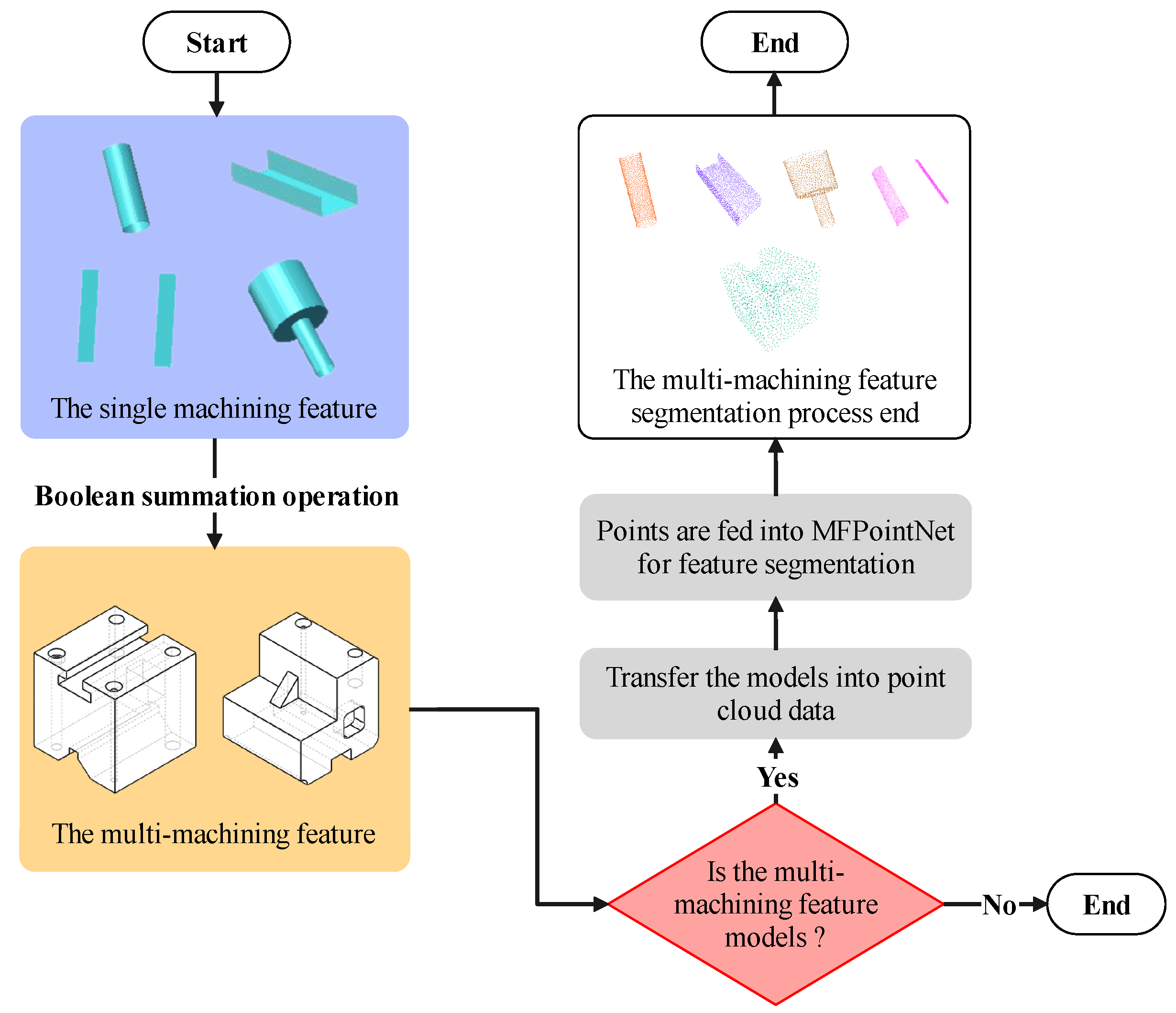
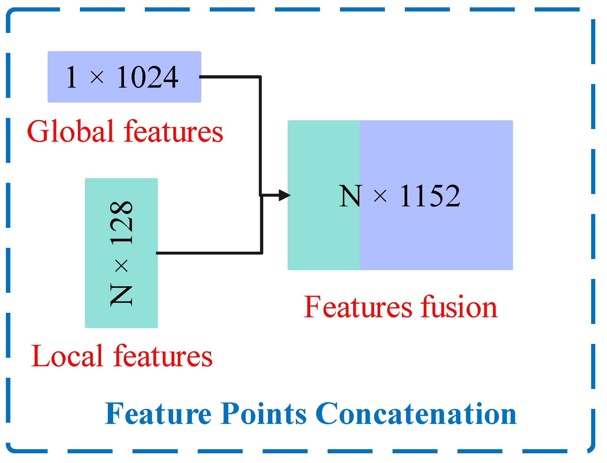
The overall procedure for the multi-feature recognition task is shown in Figure 7. Firstly, the multi-feature models are established by Boolean operation according to the MFDataset. These models are in STL format. Secondly, a transformation process will be used to convert into the point cloud models. Thirdly, we input the feature point cloud models into MFPointNet directly. As to the intersecting features, MFPointNet concatenates global features with previously learned local features of each feature point, which is shown in Figure 8, and then passes MLP to obtain the classification labels for each machining feature point.
As illustrated in Figure 6 and Figure 8, the multi-machining feature segmentation network is an extension of single-machining feature classification network. After finding the global feature points, we feed it back to per-point features by concatenating the global feature with each of the local features. Then we extract the new point features based on the combined features-both the local feature information and global feature information are taken into account. Therefore, the N × 128 output features obtained by feature extraction and the 1 × 1024 output features are fused to obtain N × 1152 output features. After the SDL module, the (3N/4) × 1152 output feature points are received. For each of the (3N/4) feature points, the segmentation network will output the corresponding m scores. m represents the semantic feature subcategories. Because the multi-machining feature model is based on MFDataset, m here is equal to a fixed value of 33. This is followed by four convolutional layers, each with 512, 256, 128, and 33 convolution kernels of size 1 × 1, respectively, and we can get the final (3N/4) × 33 output machining feature point labels.

5. Experimental Results and Discussion

Based on MFPointNet proposed in Section 4 and the machining feature dataset MFDataset presented in Section 3, the effect of different numbers of input points on recognition accuracy is shown in this section. Moreover, we compare MFPointNet to PointNet [12], PointNet++ [13], PointCNN [14], and DGCNN [15] in terms of the recognition accuracy and complexity model size under the different input points. In multi-machining feature recognition, the multi-machining feature segmented into single-machining features is analyzed.
All the experiments in this paper are conducted on the “High Performance Computing Public Service Platform of Huazhong University of Science and Technology” platform, using Pytorch [67] as the deep learning framework. Moreover, the platform is available in the following configurations: a Linux Operating System with NVIDIA Tesla V100S GPU, 32 GB memory, and Intel Xeon Gold 6230R CPU with 256 GB memory.
The network training parameters are set as follows: the default setting for the number of input points is 1024 (alternatives are 256 and 512). The maximum number of training iteration epochs is set to 200. The batch size is set to 64. The initial learning rate is 0.001. The optimizer is Adam. The decay rate is 0.0001. The number of categories is set to 33. The loss function is set to cross entropy (CE). The point cloud dataset is not used with normal vectors, i.e., use normals == false. The dataset is divided into the training set (70% of the whole dataset) and the testing set (30% of the whole dataset).

5.1. Single-Machining Feature Recognition

In this section, experimental results of MFPointNet and comparative experiments with other point cloud-based neural networks are shown separately.

5.1.1. The MFPointNet Experimental Results

To demonstrate the performance of MFPointNet, we use the training epoch number, average epoch time, total training time, training model size, network parameters, and overall classification accuracy as the evaluation indicators on MFDataset. We have used 256 points, 512 points, and 1024 points successively as the original input point numbers in the network. To verify the effect of input normal vectors on the experiment results, we added a set of experiments using the 1024 points with normal vectors as the input. The relevant experimental results are shown in Table 2. As can be seen from Table 2, the average training epoch time and network parameters definitely do not increase linearly with the number of input points but remain essentially unchanged. Compared to 256 and 512 input points, the classification accuracy of 1024 input points is slightly higher, reaching 98.93%. The model size with normal vectors is only a bit more than without them, but the classification accuracy reaches 99.60% clearly. The classification recognition accuracy with normal vectors is the highest among the four experiment groups.

5.1.2. Comparative Experiments of Effect on Input Point Number with Other Point Cloud-Based Networks

Table 3 shows the effect of different input point numbers on the network training parameters and recognition accuracy. As can be seen from Table 3, the parameters for different networks do not change at all as the input point number varies. This is due to the fact that these neural networks have shared weights and the different input sizes will not affect the network parameters. The parameters of MFPointNet are the largest due to the successive use of MLP. The parameters of the PointCNN network are the smallest, owing to the X-Conv architecture. Moreover, the recognition accuracy increases with the number of input points, regardless of the network. The recognition accuracy of the MFPointNet network is highest when the number of input points is 256 and 1024, respectively, while the recognition accuracy of the MFPointNet is slightly lower than that of PointNet++ when the number of input points is 512.
Table 4 shows the effect of different input feature point numbers on the network training time and model complexity size. Despite the increasing number of input feature points, the training time per epoch for all the methods remains largely unchanged, with the exception of PointCNN. The average epoch training time of MFPointNet is twice that of PointNet and close to that of PointNet++. The longer training time per epoch for MFPointNet may be caused by the fact that MFPointNet takes some time to go through the SDL module and MLP. On the other hand, the training time for PointCNN basically increases linearly with the number of input points. It is mainly because in every training epoch a transformation matrix X needs to be learned. This poses some difficulties for network training.
The model size of each network grows essentially linearly as the number of input feature points increases, in which that of the PointCNN is the smallest. It is mainly because the convolution operation uses separable convolution to reduce the parameters and computational consumption. Although the model size of MFPointNet is slightly higher than that of PointCNN, it is the smallest compared to PointNet, PointNet++, and DGCNN. It may be because of the use of the SDL module, which only selects the more important points for network training. In addition, as can be seen in Table 4, when the number of input feature points increases from 256 to 1024, the model size of PointNet, PointNet++, and DGCNN increases by a factor of four. Meanwhile, MFPointNet only increases by a factor of two, from 0.10676 G to 0.21725 G. This illustrates that MFPointNet is more robust to model complexity when more machining feature points are input to the neural network. In general, MFPointNet can reduce the network model complexity size while ensuring the feature recognition accuracy.

5.1.3. Comparative Experiments of Effect on Input Normal Vectors with Other Point Cloud-Based Networks

To verify the effect of the input normal vector on the network parameters and recognition accuracy, some comparative experiments are done as shown in Table 5, while keeping the input point number constant at 1024. When we use an input point with normal vectors compared to that without normal vectors, the network parameters increase slightly. This is due to the change of parameters in the head part of the network, which is caused by the input normal vectors.
As can be seen from Table 5, regardless of the network, the recognition accuracy with input normal vectors is higher than that without input normal vectors. This is because the normal vectors in the x, y, and z directions contain more feature information, which helps to improve the classification accuracy. MFPointNet achieves the highest recognition accuracy of 98.93% when no normal vectors are input, but PointNet++ achieves the highest accuracy when normal vectors are used.
The influence of normal vectors on training time and model complexity size is shown in Table 6. Having no vector input has essentially no effect on the training every epoch time. MFPointNet takes only slightly more epoch time than PointNet++, while DGCNN takes the least training epoch time. As is illustrated in Table 6, the model size of the input normal vector is slightly more than that of the no normal vector input. The model size of MFPointNet is the least computationally intensive in comparison, being only slightly more than that of PointCNN. This is due to the downsampling of the SDL module.

5.2. Multi-Machining Feature Recognition

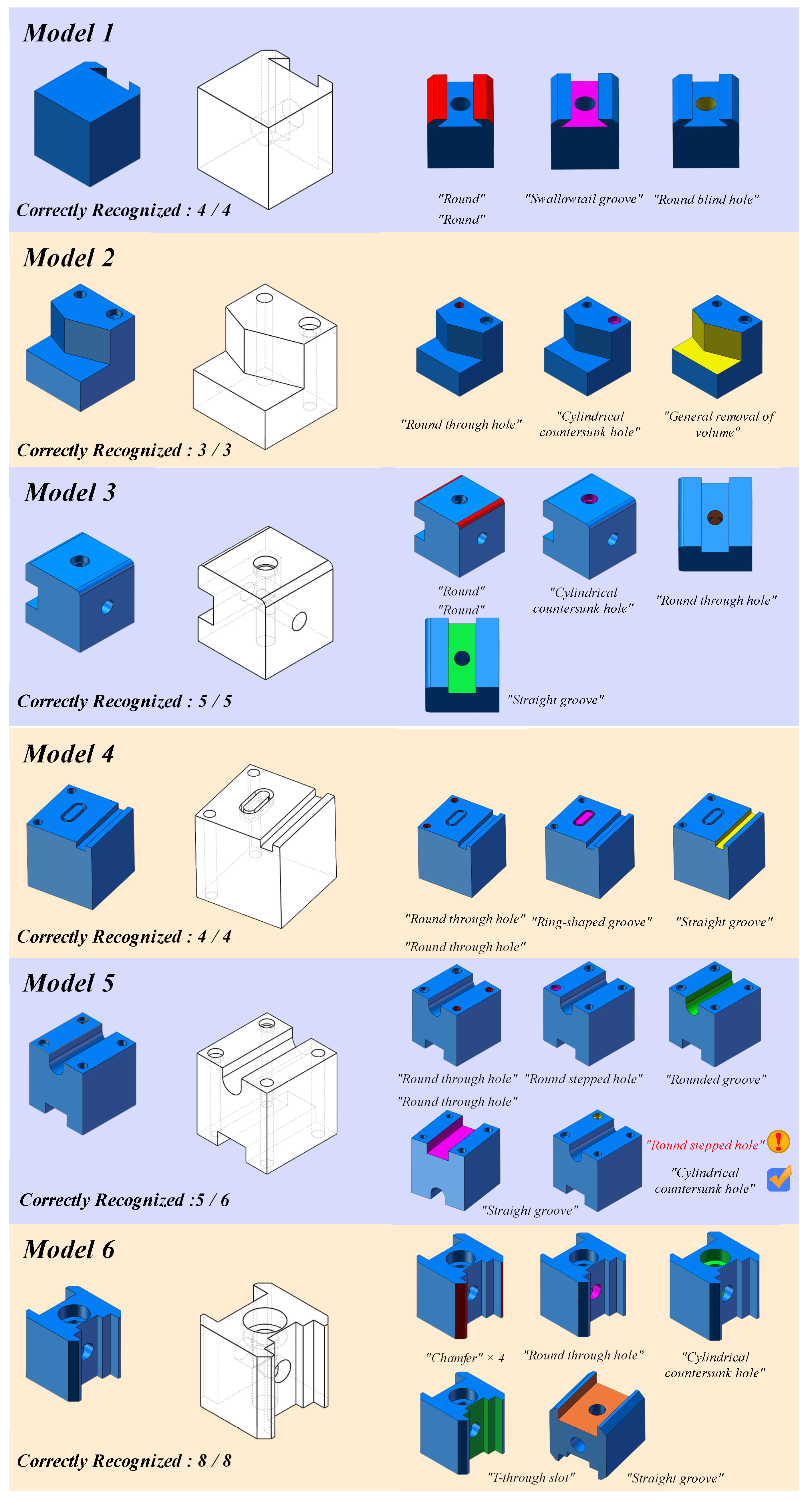
To demonstrate the segmentation performance of the MFPointNet, nine test models with varied intersecting features are used to recognize the multi-machining features. The related results are shown in Figure 9 and Figure 10. As can be seen in Figure 9 and Figure 10, MFPointNet identifies all the segment features correctly for slightly intersecting models. For the two moderately intersecting models, 13 of the 14 machining features can be recognized correctly. It is worth noting that the cylindrical countersunk hole feature has been misrecognized as a round stepped hole. This may be due to the fact that these two features are simply similar and the connecting surfaces are not expressed accurately. For the three highly intersecting models in Figure 10, 23 of the 25 features are recognized correctly.
The misclassification of closed pockets as general step features in Model 7 is probably caused by the confusing intersection between the closed pocket and the straight groove in depth. Furthermore, the rounding feature in Model 9 is incorrectly classified as the round, which is a failure of recognition for MFPointNet. In general, 52 out of 55 machining features are segmented and recognized, with a recognition accuracy of 94.54%. In future work, we intend to establish multi-machining feature datasets, rather than the few models here, to train the neural network to get better recognition accuracy.

6. Conclusions

Machining feature recognition plays an important role in the 3D machining process. In this paper, we propose a neural network MFPointNet, utilizing the selective downsampling layer of the input point to achieve the machining feature recognition. The presented selective downsampling algorithm works by dropping out unimportant points while keeping the important ones. It is proven to reduce the computational model size without accuracy loss. We establish the MFDataset feature dataset. Then the extraction of machining feature surface point sets is adopted to get the corresponding feature data separately, followed by Poisson-disk sampling. In single-feature recognition, we use MFPointNet to train the 256, 512, and 1024 input points. Moreover, the impact of normal vector input is also studied in our method. Experimental results show that compared with other point cloud-based networks, MFPointNet can get a higher single-feature classification accuracy based on the original input point 1024. Due to the selective downsampling layer, the computational model size of MFPointNet is smaller than other point cloud-based networks in general. MFPointNet is more robust to model complexity when more machining feature points are input to the neural network. Compared with the 256 and 512 input points, the classification accuracy of 1024 input points is a bit higher, reaching 98.93%. The model size with normal vectors is only a little more than that without them, but the classification accuracy reaches 99.60%. In multi-machining feature recognition, nine intersecting feature models are made to test MFPointNet’s segmentation performance. Experimental results demonstrate that 52 of the overall 55 machining features are segmented and recognized, with a segmentation accuracy of 94.54%. As this paper is still mainly focused on single-feature recognition, the multi-machining feature dataset creation and a better multi-feature segmentation network will be carried out in future work.

Author Contributions

Conceptualization, R.L.; methodology, R.L.; software, R.L.; validation, R.L.; formal analysis, R.L.; investigation, R.L.; resources, R.L.; data curation, R.L.; writing—original draft preparation, R.L.; writing—review and editing, Y.P.; visualization, R.L.; supervision, H.W.; project administration, Y.P.; funding acquisition, Y.P. All authors have read and agreed to the published version of the manuscript.

Funding

This work was sponsored by the National Key Research and Development Program of China (No.2022YFB3304100).

Institutional Review Board Statement

Not applicable.

Informed Consent Statement

Not applicable.

Data Availability Statement

All the related data generated during this research are included in the article, and the data that support the conclusion of this study are openly available by https://github.com/leiruoshan/MFPointNet_feature_dataset (accessed on 2 June 2022).

Acknowledgments

Thanks for the support by the National Key Research and Development Program of China (No.2022YFB3304100).

Conflicts of Interest

The authors declare no conflict of interest.

Appendix A

Figure A1. The overall machining features contained in MFDataset.
Machines 10 01165 g0a1aMachines 10 01165 g0a1b

Appendix B

Figure A2. The machining feature surface point extraction results of MFDataset.
Machines 10 01165 g0a2

Appendix C

Figure A3. The 512-point sampling models of MFDataset.
Machines 10 01165 g0a3

Appendix D

Figure A4. The 256-point sampling models of MFDataset.
Machines 10 01165 g0a4

References

  1. Ding, S.; Feng, Q.; Sun, Z.; Ma, F. MBD Based 3D CAD Model Automatic Feature Recognition and Similarity Evaluation. IEEE Access 2021, 9, 150403–150425. [Google Scholar] [CrossRef]
  2. Shi, Y.; Zhang, Y.; Xia, K.; Harik, R. A critical review of feature recognition techniques. Comput.-Aided Des. Appl. 2020, 17, 861–899. [Google Scholar] [CrossRef]
  3. Deng, L.; Yu, D. Deep learning: Methods and applications. Found. Trends Signal Process. 2014, 7, 197–387. [Google Scholar] [CrossRef] [Green Version]
  4. Fougères, A.J.; Ostrosi, E. Intelligent agents for feature modelling in computer aided design. J. Comput. Des. Eng. 2018, 05, 19–40. [Google Scholar] [CrossRef]
  5. Zhao, P.; Sheng, B. Recognition method of process feature based on delta-volume decomposition and combination strategy. J. South China Univ. Technol. (Natural Sci. Ed.) 2011, 39, 30–35. (In Chinese) [Google Scholar]
  6. Han, J.H.; Requicha, A.A.G. Integration of feature based design and feature recognition. Comput. Aided Des. Appl. 1997, 29, 393–403. [Google Scholar] [CrossRef]
  7. Zehtaban, L.; Roller, D. Automated rule-based system for Opitz feature recognition and code generation from STEP. Comput.-Aided Des. Appl. 2016, 13, 309–319. [Google Scholar] [CrossRef]
  8. Zhang, Y.; Luo, X.; Zhang, B.; Zhang, S. Semantic approach to the automatic recognition of machining features. Int. J. Adv. Manuf. Technol. 2017, 89, 417–437. [Google Scholar] [CrossRef]
  9. Woo, Y.; Wang, E.; Kim, Y.S.; Rho, H.M. A hybrid feature recognizer for machining process planning systems. CIRP Ann. 2005, 54, 397–400. [Google Scholar] [CrossRef]
  10. Wu, M.C.; Lit, C.R. Analysis on machined feature recognition techniques based on B-rep. Comput.-Aided Des. 1996, 28, 603–616. [Google Scholar] [CrossRef]
  11. Sakurai, H.; Gossard, D.C. Recognizing shape features in solid models. IEEE Comput. Graph. Appl. 1990, 10, 22–32. [Google Scholar] [CrossRef]
  12. Qi, C.R.; Su, H.; Mo, K.; Guibas, L.J. Pointnet: Deep learning on point sets for 3d classification and segmentation. In Proceedings of the IEEE Conference on Computer Vision and Pattern Recognition, Honolulu, HI, USA, 21–26 July 2017; pp. 652–660. [Google Scholar]
  13. Qi, C.R.; Yi, L.; Su, H.; Guibas, L.J. Pointnet++: Deep hierarchical feature learning on point sets in a metric space. In Proceedings of the Advances in Neural Information Processing Systems 30: Annual Conference on Neural Information Processing Systems 2017, Long Beach, CA, USA, 4–9 December 2017; Volume 30. [Google Scholar]
  14. Li, Y.; Bu, R.; Sun, M.; Wu, W.; Di, X.; Chen, B. Pointcnn: Convolution on x-transformed points. In Proceedings of the Advances in Neural Information Processing Systems 31: Annual Conference on Neural Information Processing Systems 2018, NeurIPS 2018, Montréal, QC, Canada, 3–8 December 2018; Volume 31. [Google Scholar]
  15. Wang, Y.; Sun, Y.; Liu, Z.; Sarma, S.E.; Bronstein, M.M.; Solomon, J.M. Dynamic graph cnn for learning on point clouds. ACM Trans. Graph. TOG 2019, 38, 1–12. [Google Scholar] [CrossRef] [Green Version]
  16. Yao, X.; Wang, D.; Yu, T.; Luan, C.; Fu, J. A machining feature recognition approach based on hierarchical neural network for multi-feature point cloud models. J. Intell. Manuf. 2022, 1–12. [Google Scholar] [CrossRef]
  17. Keller, J.M.; Gray, M.R.; Givens, J.A. A fuzzy k-nearest neighbor algorithm. IEEE Trans. Syst. Man Cybern. 1985, 4, 580–585. [Google Scholar] [CrossRef]
  18. Nezhadarya, E.; Taghavi, E.; Razani, R.; Liu, B.; Luo, J. Adaptive hierarchical down-sampling for point cloud classification. In Proceedings of the IEEE/CVF Conference on Computer Vision and Pattern Recognition, Seattle, WA, USA, 13–19 June 2020; pp. 12956–12964. [Google Scholar]
  19. Tolstikhin, I.O.; Houlsby, N.; Kolesnikov, A.; Beyer, L.; Zhai, X.; Unterthiner, T.; Dosovitskiy, A. Mlp-mixer: An all-mlp architecture for vision. Adv. Neural Inf. Process. Syst. 2021, 34, 24261–24272. [Google Scholar]
  20. Joshi, S.; Chang, T.C. Graph-based heuristics for recognition of machined features from a 3D solid model. Comput. Aided Des. 1988, 20, 58–66. [Google Scholar] [CrossRef]
  21. Gao, S.; Shah, J.J. Automatic recognition of interacting machining features based on minimal condition subgraph. Comput. Aided Des. 1998, 30, 727–739. [Google Scholar] [CrossRef]
  22. Yeo, C.; Cheon, S.; Mun, D. Manufacturability evaluation of parts using descriptor-based machining feature recognition. Int. J. Comput. Integr. Manuf. 2021, 34, 1196–1222. [Google Scholar] [CrossRef]
  23. Xu, T.; Li, J.; Chen, Z. Automatic machining feature recognition based on MBD and process semantics. Comput. Ind. 2022, 142, 103736. [Google Scholar] [CrossRef]
  24. Shi, Y.; Zhang, Y.; Harik, R. Manufacturing feature recognition with a 2D convolutional neural network. CIRP J. Manuf. Sci. Technol. 2020, 30, 36–57. [Google Scholar] [CrossRef]
  25. Dimov, S.S.; Brousseau, E.B.; Setchi, R. A hybrid method for feature recognition in computer-aided design models. Proc. Inst. Mech. Eng. 2007, 221, 79–96. [Google Scholar] [CrossRef]
  26. Cao, W.; Robinson, T.; Hua, Y. Graph representation of 3D CAD models for machining feature recognition with deep learning. In Proceedings of the International Design Engineering Technical Conferences and Computers and Information in Engineering Conference, Virtual, 17–19 August 2020; Volume 84003. [Google Scholar]
  27. Verma, A.K.; Rajotia, S. A hint-based machining feature recognition system for 2.5 D parts. Int. J. Prod. Res. 2008, 46, 1515–1537. [Google Scholar] [CrossRef]
  28. Fu, M.W.; Ong, S.K.; Lu, W.F.; Lee, I.B.H.; Nee, A.Y. An approach to identify design and manufacturing features from a data exchanged part model. Comput. Aided Des. 2003, 35, 979–993. [Google Scholar] [CrossRef]
  29. Nasr, E.S.A.; Kamrani, A.K. A new methodology for extracting manufacturing features from CAD system. Comput. Ind. Eng. 2006, 51, 389–415. [Google Scholar] [CrossRef]
  30. Li, H.; Huang, Y.; Sun, Y.; Chen, P. Hint-based generic shape feature recognition from three-dimensional B-rep models. Adv. Mech. Eng. 2015, 7, 1687814015582082. [Google Scholar] [CrossRef]
  31. Gong, L.; Xue, X.; Wang, T.; Wu, T.; Zhang, H.; Meng, Z. Machining Hole Feature Recognition Method and Application for Manufacturability Check. In Proceedings of the 6th International Conference on Virtual and Augmented Reality Simulations, Brisbane, Australia, 22–27 June 2014; pp. 76–84. [Google Scholar]
  32. Kataraki, P.S.; Abu Mansor, M.S. Auto-recognition and generation of material removal volume for regular form surface and its volumetric features using volume decomposition method. Int. J. Adv. Manuf. Technol. 2017, 90, 1479–1506. [Google Scholar] [CrossRef]
  33. Zubair, A.F.; Abu Mansor, M.S. Auto-recognition and part model complexity quantification of regular-freeform revolved surfaces through delta volume generations. Eng. Comput. 2020, 36, 511–526. [Google Scholar] [CrossRef]
  34. Kim, B.C.; Mun, D. Stepwise volume decomposition for the modification of B-rep models. Int. J. Adv. Manuf. Technol. 2014, 75, 1393–1403. [Google Scholar] [CrossRef]
  35. Kwon, S.; Mun, D.; Kim, B.C.; Han, S.; Suh, H.-W. B-rep model simplification using selective and iterative volume decomposition to obtain finer multi-resolution models. Comput. Aided Des. 2019, 112, 23–34. [Google Scholar] [CrossRef]
  36. Woo, Y.; Sakurai, H. Recognition of maximal features by volume decomposition. Comput. Aided Des. 2002, 34, 195–207. [Google Scholar] [CrossRef]
  37. Gupta, M.K.; Swain, A.K.; Jain, P.K. A novel approach to recognize interacting features for manufacturability evaluation of prismatic parts with orthogonal features. Int. J. Adv. Manuf. Technol. 2019, 105, 343–373. [Google Scholar] [CrossRef]
  38. Verma, A.K.; Rajotia, S. A hybrid machining Feature Recognition system. Int. J. Manuf. Res. 2009, 4, 343–361. [Google Scholar] [CrossRef]
  39. Rameshbabu, V.; Shunmugam, M.S. Hybrid feature recognition method for setup planning from STEP AP-203. Robot. Comput.-Integr. Manuf. 2009, 25, 393–408. [Google Scholar] [CrossRef]
  40. Jong, W.R.; Lai, P.J.; Chen, Y.W.; Ting, Y.H. Automatic process planning of mold components with integration of feature recognition and group technology. Int. J. Adv. Manuf. Technol. 2015, 78, 807–824. [Google Scholar] [CrossRef]
  41. Guo, L.; Zhou, M.; Lu, Y.; Yang, T.; Yang, F. A hybrid 3D feature recognition method based on rule and graph. Int. J. Comput. Integr. Manuf. 2021, 34, 257–281. [Google Scholar] [CrossRef]
  42. Al-wswasi, M.; Ivanov, A. A novel and smart interactive feature recognition system for rotational parts using a STEP file. Int. J. Adv. Manuf. Technol. 2019, 104, 261–284. [Google Scholar] [CrossRef] [Green Version]
  43. Sunil, V.B.; Agarwal, R.; Pande, S.S. An approach to recognize interacting features from B-Rep CAD models of prismatic machined parts using a hybrid (graph and rule based) technique. Comput. Ind. 2010, 61, 686–701. [Google Scholar] [CrossRef]
  44. Zhang, Z.; Jaiswal, P.; Rai, R. Featurenet: Machining feature recognition based on 3D convolution neural network. Comput. Aided Des. 2018, 101, 12–22. [Google Scholar] [CrossRef]
  45. Ghadai, S.; Balu, A.; Sarkar, S.; Krishnamurthy, A. Learning localized features in 3D CAD models for manufacturability analysis of drilled holes. Comput. Aided Geom. Des. 2018, 62, 263–275. [Google Scholar] [CrossRef]
  46. Ning, F.; Shi, Y.; Cai, M.; Xu, W. Part machining feature recognition based on a deep learning method. J. Intell. Manuf. 2021, 2021, 1–13. [Google Scholar] [CrossRef]
  47. Peddireddy, D.; Fu, X.; Shankar, A.; Wang, H.; Joung, B.G.; Aggarwal, V.; Jun, M.B.G. Identifying manufacturability and machining processes using deep 3D convolutional networks. J. Manuf. Process. 2021, 64, 1336–1348. [Google Scholar] [CrossRef]
  48. Lee, H.; Lee, J.; Kim, H.; Mun, D. Dataset and method for deep learning-based reconstruction of 3D CAD models containing machining features for mechanical parts. J. Comput. Des. Eng. 2022, 9, 114–127. [Google Scholar] [CrossRef]
  49. Lee, J.; Lee, H.; Mun, D. 3D convolutional neural network for machining feature recognition with gradient-based visual explanations from 3D CAD models. Sci. Rep. 2022, 12, 14864. [Google Scholar] [CrossRef] [PubMed]
  50. Yeo, C.; Kim, B.C.; Cheon, S.; Lee, J.; Mun, D. Machining feature recognition based on deep neural networks to support tight integration with 3D CAD systems. Sci. Rep. 2021, 11, 22147. [Google Scholar] [CrossRef] [PubMed]
  51. Zhang, Y.; Zhang, Y.; He, K.; Li, D.; Xu, X.; Gong, Y. Intelligent feature recognition for STEP-NC-compliant manufacturing based on artificial bee colony algorithm and back propagation neural network. J. Manuf. Syst. 2022, 62, 792–799. [Google Scholar] [CrossRef]
  52. Shi, Y.; Zhang, Y.; Baek, S.; De Backer, W.; Harik, R. Manufacturability analysis for additive manufacturing using a novel feature recognition technique. Comput. Aided Des. Appl. 2018, 15, 941–952. [Google Scholar] [CrossRef] [Green Version]
  53. Shi, P.; Qi, Q.; Qin, Y.; Scott, P.J.; Jiang, X. A novel learning-based feature recognition method using multiple sectional view representation. J. Intell. Manuf. 2020, 31, 1291–1309. [Google Scholar] [CrossRef] [Green Version]
  54. Shi, P.; Qi, Q.; Qin, Y.; Scott, P.J.; Jiang, X. Intersecting machining feature localization and recognition via single shot multibox detector. IEEE Trans. Ind. Inform. 2020, 17, 3292–3302. [Google Scholar] [CrossRef]
  55. Shi, P.; Qi, Q.; Qin, Y.; Scott, P.J.; Jiang, X. Highly interacting machining feature recognition via small sample learning. Robot. Comput.-Integr. Manuf. 2022, 73, 102260. [Google Scholar] [CrossRef]
  56. Colligan, A.R.; Robinson, T.T.; Nolan, D.C.; Hua, Y. Point Cloud Dataset Creation for Machine Learning on CAD Models. Comput. Aided Des. Appl. 2021, 18, 760–771. [Google Scholar] [CrossRef]
  57. Zhang, H.; Zhang, S.; Zhang, Y.; Liang, J.; Wang, Z. Machining feature recognition based on a novel multi-task deep learning network. Robot. Comput.-Integr. Manuf. 2022, 77, 102369. [Google Scholar] [CrossRef]
  58. Worner, J.M.; Brovkina, D.; Riedel, O. Feature recognition for graph-based assembly product representation using machine learning. In Proceedings of the 2021 21st International Conference on Control, Automation and Systems (ICCAS), Jeju, Republic of Korea, 12–15 October 2021; pp. 629–635. [Google Scholar]
  59. Liu, C.; Li, Y.; Li, Z. A machining feature definition approach by using two-times unsupervised clustering based on historical data for process knowledge reuse. J. Manuf. Syst. 2018, 49, 16–24. [Google Scholar] [CrossRef]
  60. Sharma, R.; Gao, J.X. Implementation of STEP Application Protocol 224 in an automated manufacturing planning system. Proc. Inst. Mech. Eng. Part B J. Eng. Manuf. 2002, 216, 1277–1289. [Google Scholar] [CrossRef] [Green Version]
  61. Bowers, J.; Wang, R.; Wei, L.-Y.; Maletz, D. Parallel Poisson disk sampling with spectrum analysis on surfaces. ACM Trans. Graph. TOG 2010, 29, 1–10. [Google Scholar] [CrossRef]
  62. Corsini, M.; Cignoni, P.; Scopigno, R. Efficient and flexible sampling with blue noise properties of triangular meshes. IEEE Trans. Vis. Comput. Graph. 2012, 18, 914–924. [Google Scholar] [CrossRef] [Green Version]
  63. Cignoni, P.; Callieri, M.; Corsini, M.; Dellepiane, M.; Ganovelli, F.; Ranzuglia, G. Meshlab: An open-source mesh processing tool. In Proceedings of the Eurographics Italian Chapter Conference, Salerno, Italy, 2–4 July 2008; pp. 129–136. [Google Scholar]
  64. Brands, S. Rapid demonstration of linear relations connected by boolean operators. In Proceedings of the International Conference on the Theory and Applications of Cryptographic Techniques, Konstanz, Germany, 11–15 May 1997; pp. 318–333. [Google Scholar]
  65. Odena, A.; Dumoulin, V.; Olah, C. Deconvolution and checkerboard artifacts. Distill 2016, 1, e3. [Google Scholar] [CrossRef]
  66. Gardner, M.W.; Dorling, S.R. Artificial neural networks (the multilayer perceptron)—A review of applications in the atmospheric sciences. Atmos. Environ. 1998, 32, 2627–2636. [Google Scholar] [CrossRef]
  67. Paszke, A.; Gross, S.; Massa, F.; Lerer, A.; Bradbury, J.; Chanan, G.; Killeen, T.; Lin, Z.; Gimelshein, N.; Antiga, L.; et al. Pytorch: An imperative style, high-performance deep learning library. In Proceedings of the Advances in Neural Information Processing Systems 32: Annual Conference on Neural Information Processing Systems 2019, NeurIPS 2019, Vancouver, BC, Canada, 8–14 December 2019; Volume 32. [Google Scholar]
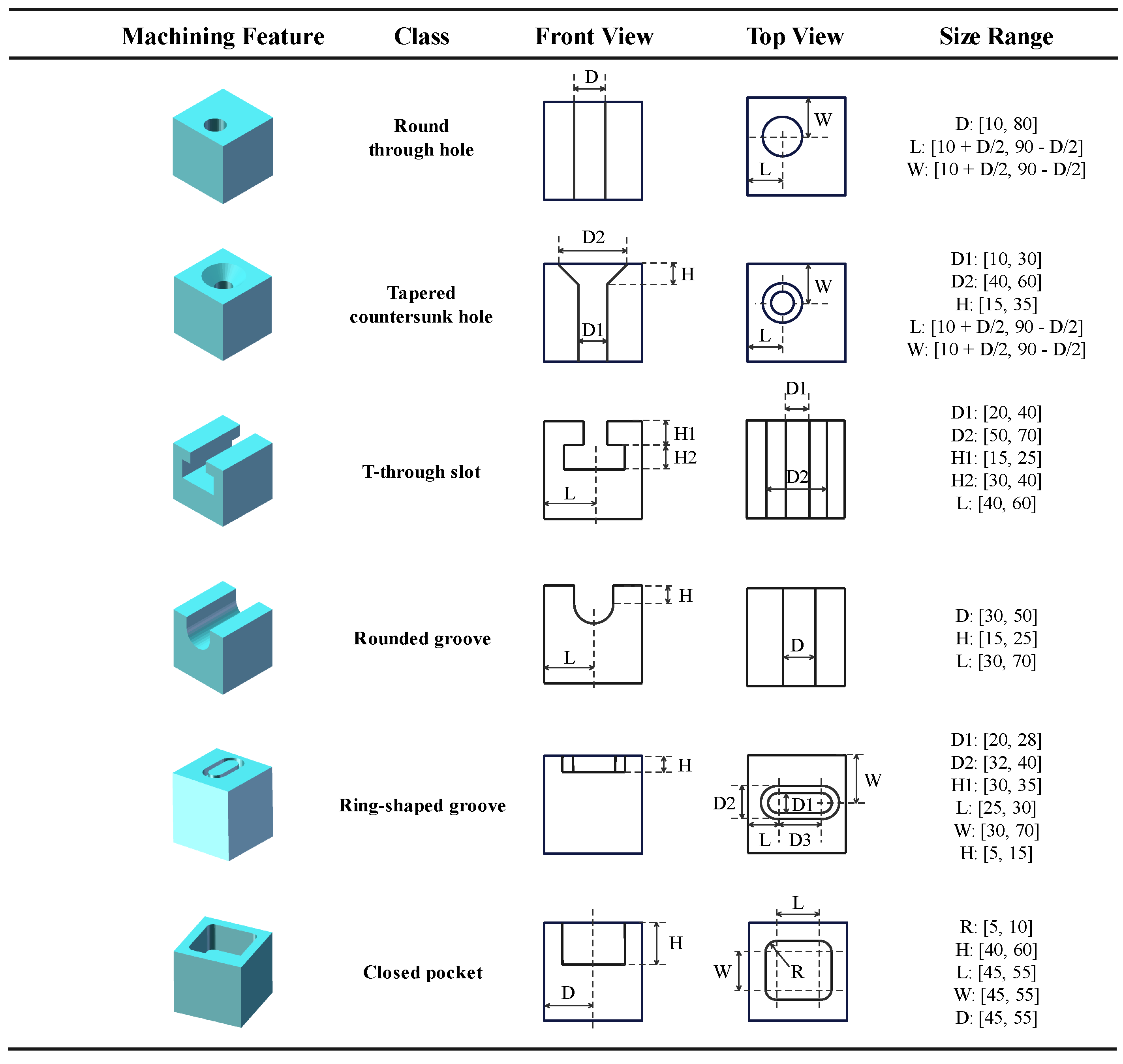
Figure 1. Some non-rotary feature models contained in MFDataset.
Machines 10 01165 g001
Figure 2. Some rotary machining feature models in MFDataset.
Machines 10 01165 g002
Figure 3. Flow chart of the point cloud machining feature dataset creation.
Machines 10 01165 g003
Figure 4. Some machining feature point cloud models.
Machines 10 01165 g004
Figure 5. The description of selective downsampling layer.
Machines 10 01165 g005
Figure 6. The structure of MFPointNet combining the classification network and segmentation network.
Machines 10 01165 g006
Figure 7. The procedure of multi-machining feature segmentation and recognition.
Machines 10 01165 g007
Figure 8. The process of machining feature point concatenation.
Machines 10 01165 g008
Figure 9. Multi-machining feature recognition results on several 3D CAD models. Each model contains a 3D model entity, a 3D perspective view, and the segmentation results. For every model, the correctly recognized result equals the true feature types divided by the segment-identified types.
Machines 10 01165 g009
Figure 10. Multi-machining feature recognition results on three complex 3D CAD models. For every model, the correctly recognized result equals the true feature types divided by the segment-identified number. The different colors of each model represent the various segment recognition results.
Machines 10 01165 g010
Table 1. The detailed description of the multi-machining feature dataset.
Model DefinitionNumber of Feature TypesFeature CategoriesIntersecting Degrades
Model 1302 + 10 + 24slight
Model 2301 + 03 + 30slight
Model 3401 + 03 + 15 + 23slight
Model 4401 + 01 + 15 + 16slight
Model 5501 + 03 + 05 + 09 + 15moderate
Model 6501 + 03 + 07 + 15 + 24moderate
Model 7601 + 03 + 05 + 15 + 23 + 32high
Model 8701 + 02 + 03 + 04 + 07 + 08 + 30high
Model 9802 + 04 + 15 + 23 + 24 + 25 + 30 + 31high
Table 2. The experimental results of MFPointNet.
Input Point NumbersUsing Normal VectorsTraining Epoch NumberAverage Epoch TimeTotal Training TimeTraining Model SizeNetwork ParametersOverall Classification Accuracy
256No185470.9 s24.20 h0.1067 G5.2118M96.88%
512No188474.8 s24.79 h0.1435 G98.09%
1024No190490.4 s25.88 h0.2172 G98.93%
Yes189488.8 s25.66 h0.2188 G99.60%
Table 3. The effect of input point numbers on recognition accuracy and parameters.
MethodsInput Point NumbersNetwork ParametersOverall AccuracyMean Class Accuracy
PointNet [12]2563.469674M96.41%96.12%
PointNet++ [13]1.745569M96.82%96.58%
PointCNN [14]0.275449M94.42%94.04%
DGCNN [15]1.810849M95.02%94.88%
MFPointNet5.211882M96.88%96.20%
PointNet [12]5123.469674M97.33%96.95%
PointNet++ [13]1.745569M98.35%97.99%
PointCNN [14]0.275449M96.37%95.96%
DGCNN [15]1.810849M97.75%97.01%
MFPointNet5.211882M98.09%97.23%
PointNet [12]10243.469674M98.05%97.09%
PointNet++ [13]1.745569M98.34%97.20%
PointCNN [14]0.275449M98.89%97.75%
DGCNN [15]1.810849M98.59%97.56%
MFPointNet5.211882M98.93%97.99%
Table 4. The effect of input point numbers on training time and model complexity size.
MethodsInput Point NumbersTraining Epoch NumberAverage Epoch TimeTotal Training TimeModel Complexity Size
PointNet [12]256184200.9 s10.27 h0.11393 G
PointNet++ [13]178430.8 s21.30 h1.02956 G
PointCNN [14]174746.4 s36.08 h0.04760 G
DGCNN [15]190190.8 s10.07 h0.62470G
MFPointNet185470.9 s24.20 h0.10676 G
PointNet [12]512165199.8 s9.16 h0.22484 G
PointNet++ [13]196441.3 s24.03 h2.09457 G
PointCNN [14]1792127.7 s105 h0.06665 G
DGCNN [15]175194.0 s9.43 h1.24821 G
MFPointNet188474.8 s24.79 h0.14359 G
PointNet [12]1024200200.2 s11.12 h0.44704 G
PointNet++ [13]199447.2 s24.72 h4.01569 G
PointCNN [14]1887340.8 s383.35 h0.10476 G
DGCNN [15]185199.8 s10.27 h2.49523 G
MFPointNet194490.4 s26.43 h0.21725 G
Table 5. The effect of normal vectors on recognition accuracy and network parameters.
MethodsInput Point NumbersUsing Normal VectorsNetwork ParametersOverall AccuracyMean Class Accuracy
PointNet [12]1024No3.469674M98.05%97.09%
PointNet++ [13]1.745569M98.34%97.20%
PointCNN [14]0.275449M98.89%97.75%
DGCNN [15]1.810849M98.59%97.56%
MFPointNet5.211882M98.93%97.99%
PointNet [12]1024Yes3.470058M99.94%98.56%
PointNet++ [13]1.746049M99.96%98.79%
PointCNN [14]0.280056M99.03%98.09%
DGCNN [15]1.820042M99.54%98.23%
MFPointNet5.211882M99.80%98.55%
Table 6. The effect of normal vectors on training time and model complexity size.
MethodsInput Point NumbersUsing Normal VectorsTraining Epoch NumberAverage Epoch TimeTotal Training TimeModel Complexity Size
PointNet [12]1024No200200.2 s11.12 h0.44704 G
PointNet++ [13]199447.2 s24.72 h4.01569 G
PointCNN [14]1887340.8 s383.35 h0.10476 G
DGCNN [15]185199.8 s10.27 h2.49523 G
MFPointNet194490.4 s26.43 h0.21725 G
PointNet [12]1024Yes147200.5 s8.19 h0.44664 G
PointNet++ [13]189448.2 s23.53 h4.02960 G
PointCNN [14]1917336.6 s389.25 h0.11257 G
DGCNN [15]190200.1 s10.56 h2.50613 G
MFPointNet189488.8 s25.66 h0.21885 G
Publisher’s Note: MDPI stays neutral with regard to jurisdictional claims in published maps and institutional affiliations.