Article

Horse Riding Simulator Design to Replicate Human Walking Gait for Hippotherapy in Cerebral Palsy Rehabilitation

by
Wildan Trusaji
1,*,
Ardianto Satriawan
2,*,
Septia Susanti Rahadini
3,
Muhammad Ogin Hasanuddin
2,
Casi Setianingsih
4,
Nurseptian Pratomo
5,
Mayang Cendikia Selekta
3 and
Ellyana Sungkar
3
1
Faculty of Industrial Technology, Institut Teknologi Bandung, Jl. Ganesha No. 10, Bandung 40132, Indonesia
2
School of Electrical Engineering and Informatics, Institut Teknologi Bandung, Jl. Ganesha No. 10, Bandung 40132, Indonesia
3
Department of Physical Medicine and Rehabilitation, Faculty of Medicine, Universitas Padjadjaran—Dr. Hasan Sadikin General Hospital, Bandung 40161, Indonesia
4
School of Electrical Engineering, Telkom University, Jl. Telekomunikasi No. 1, Bandung 40257, Indonesia
5
PT. Monta Cakra Teknologi, Jalan Cihanjuang No. 1 KM 5.6, Bandung Barat 40559, Indonesia
*
Authors to whom correspondence should be addressed.
Machines 2022, 10(11), 1060; https://doi.org/10.3390/machines10111060
Submission received: 18 October 2022 / Revised: 8 November 2022 / Accepted: 9 November 2022 / Published: 10 November 2022
(This article belongs to the Section Robotics, Mechatronics and Intelligent Machines)

Abstract

:
Hippotherapy is a popular rehabilitation method for children with cerebral palsy (CP), which is done by riding an actual horse or a horse riding simulator (HRS) device. Riding a real horse is more expensive than using an HRS device due to its high maintenance cost. However, most HRS devices commonly sold in the market are designed as exercise devices, not rehabilitation devices. Most of them are designed to simulate a horse’s walk, trot, canter, or gallop gait at various speeds. Hippotherapy aims to improve the walking ability of CP patients. Therefore, the device should aim to replicate the walking gait of a healthy human, the end goal of hippotherapy. This problem motivates us to design and build a specialized HRS device replicating the walking gait of a healthy human that is suitable for hippotherapy, which is achievable by simulating a horse walking gait with several adjustments. We first studied and observed the walking gait cycle of a horse, then analyzed and derived a formulation of it. We then continue by designing an HRS device using a single electrical rotational motor and mechanical means to replicate the walking gait of a horse, then tune it to an extent to replicate a human walking gait. To measure the performance of our design, we compare the gait of the user when riding our device versus walking.

1. Introduction

Cerebral palsy (CP) is a group of motor disorders caused by a non-progressive lesion in the immature brain [1]. Impaired mobility, such as difficulties in walking, is one of the most common issues experienced by children with CP, which may disrupt their daily activities [2,3]. One treatment available for children with CP is Equine Assisted Therapy (EAT), also known as hippotherapy. Hippotherapy or horseback riding exercise is a rehabilitation method that uses a horse’s movement characteristics to provide the patients with motor and sensory input [4]. It is a proven method in children with CP rehabilitation that improves motor function, symmetry of muscle contraction, posture, and walking [5]. Some researchers supported this fact by reporting positive results on randomized controlled trials and case studies of the effectiveness of hippotherapy.
Despite hippotherapy’s positive results, it has a severe drawback that needs to be considered, especially in developing countries: the cost. Taking care of a horse is a costly task to do. It requires a massive landmass for the ranch, making it impossible to do in urban areas [6]. It also requires significant human resources with particular skills that are difficult to find. A hippotherapy session also needs to be accompanied by a therapist who must have both a horse riding instructor license and therapist qualification, a rare-to-find combination of skills. All combinations of those factors make the cost of hippotherapy extraordinarily expensive.
The exorbitant cost of hippotherapy makes it unaffordable to most CP patients. The socioeconomic data of the parents of children with CP from the hospital we are affiliated with shows that the monthly income of the parents clearly can not afford 10-12 horse riding sessions in a horse ranch [7]. Moreover, hippotherapy is generally not an option available in Indonesia. The last report on it was in 2009 [8].
Using a Horse Riding Simulator (HRS) to replace actual horses in hippotherapy is one of the solutions because it significantly reduces the cost of performing hippotherapy. Hippotherapy using HRS only needs a room with all the necessary equipment, eliminating the need for a massive horse ranch in rural areas. An HRS device is commonly sold as an exercise or fitness machine. Many recent reports in the last decade [9,10,11,12,13,14,15,16,17,18,19,20,21,22,23,24,25] show that using HRS yields positive results for CP treatments similar to an actual horse’s hippotherapy.
In our previous research, we also designed a hippotherapy simulator platform using a store-bought HRS device, Jufit JFF043QM (Jufit Smart Tech, Shanghai, China) [26]. From our experiences and comparison to other studies, we learned that the HRS device sold in the market simulates various types of horse gait cycles: walk, trot, canter, and gallop at an adjustable speed. From a study, HRS devices do the motion simulation of a horse almost perfectly [27]. However, hippotherapy aims to train the patient to improve their walking and other impaired mobility. Therefore, the motion provided should simulate the walking gait of a healthy human, which motivates us to design a device that can do so.
To achieve our goal, we first study how a horse’s walking gait works because it has been observed that there are many similarities between human pelvis motions when walking and when riding on a horse [28]. We first observe how a horse walking gait cycle works: which legs are lifted and stay on the ground. We then translate them into linear movements simulating each horse’s legs. We also observe that the shoulder and hip of a horse move at different phases, which inspires us to design an HRS with two independent hip and shoulder parts. After all the calculations and designs, we build our device.
However, aside from similarities, there is some difference between human walking and horse riding motions, especially in the vertical angle tilt of the pelvis [28]. To fix this, we tune our device to match the frequency, speed, and characteristics that represent a walking gait of a healthy human. We then observe the performance of our design by comparing the movement of a healthy user when walking versus when riding our HRS device.
The rest of the paper is organized as follows. Recent studies related to horse riding simulators and their applications in CP rehabilitation are reviewed and discussed in Section 2. We then discuss the observation of a horse’s movements and our rationales to build our design in Section 3. Section 4 presents our system design in detailed explanations. Then, we discuss our design’s performance by comparing a user’s movements when riding a horse versus walking in Section 5. Section 6 discusses the future potential research and development of our design. Finally, Section 7 concludes the paper.

2. Related Research and Contribution of Our Works

We surveyed two literature areas: healthcare and mechanical engineering. The reports from healthcare fields typically use a store-bought HRS Device to conduct a case review, comparison review, or clinical trial for CP rehabilitation. Conversely, the reports from mechanical engineering fields are more concerned about designing a device that might be useful for hippotherapy.
In the healthcare field, the most common HRS devices in the studies are JOBA (Panasonic, Japan), which was used by seven teams of researchers [9,10,11,12,14,16,22], followed by FORTIS (Daewon, South Korea), which was used by five teams of researchers [13,17,19,20,21]. Another popular option is OSIM uGallop (Taiwan), used by three teams of researchers [18,23,24]. Lastly, there are SRIDER (Neiplus, Korea) [15], Shinhwa (Korea) [25], and Jufit JFF043QM (China) [26], each used by one team of researchers. However, all of the store-bought HRS devices have a similar design. All the devices claim to be able to simulate various gait types of horse movements from walk, trot, canter, and gallop at various speeds.
In the mechanical engineering field, the researchers focus on presenting how to build an HRS device that might be useful for Hippotherapy. Most of them were made to replicate actual horses’ movements with various mechanical means. However, the follow-up study of a designed horse in an actual therapy setting for CP patients is rare.
The first pioneer and significant idea of a mechanical horse as a means of therapy were proposed by Yamaguchi et al. [29] in 1991, who designed a structure that consists of swing mechanisms and a control unit. The design is claimed to be capable of simulating three types of movements: walk, trot, and canter of a horse. The design uses a linear actuator mechanism and has two actuators, one for the forelegs and the other for the hindlegs. Other researchers that also built mechanical horses include [30], Lee et al. [31], Benoit et al. [32], and Montgomery [33,34].
The horse simulators designed by Yamaguchi et al. [29] and Lott et al. [30] movements only occur in the sagittal plane and both the sagittal and transversal plane, respectively. Both designs do not have a roll movement that occurs on the frontal plane. Thus, they can not provide stimulation for pelvic obliquity movements.
The horse designs by Lee et al. [31] and Benoit et al. [32] have six degrees of freedom movement. Thus, they can produce the roll movement on the frontal plane. However, their horses only have one body segment, so they do not simultaneously simulate the roll movement of the horse’s shoulder and hip.
Montgomery researched [33] and then patented [34] a horse design capable of simultaneously producing roll movement on both shoulder and hip. The horse’s body consists of eight small rib segments, but it can not support a saddle. It may seem superficial, but a saddle has an important effect through the horse–saddle–user interaction. A saddle helps the user create a correct sitting posture and maintain balance [35].
Our horse design can generate roll movement for both shoulders and hips We achieve the movement through four sets of cam and follower connected to one motor. In addition, we build two body segments: front and back segments, to achieve different roll timing between shoulder and hip; and to provide support for saddle placement.
We summarized all the store-bought horses and designs in Table 1. We compared various factors such as the simulated horse gait, design mechanisms, number of actuators, number of body segments, movements provided, the presence of a saddle, and other remarks. In summary, compared to other researchers’ works, the novelty and main contribution of our works are the following:
1.
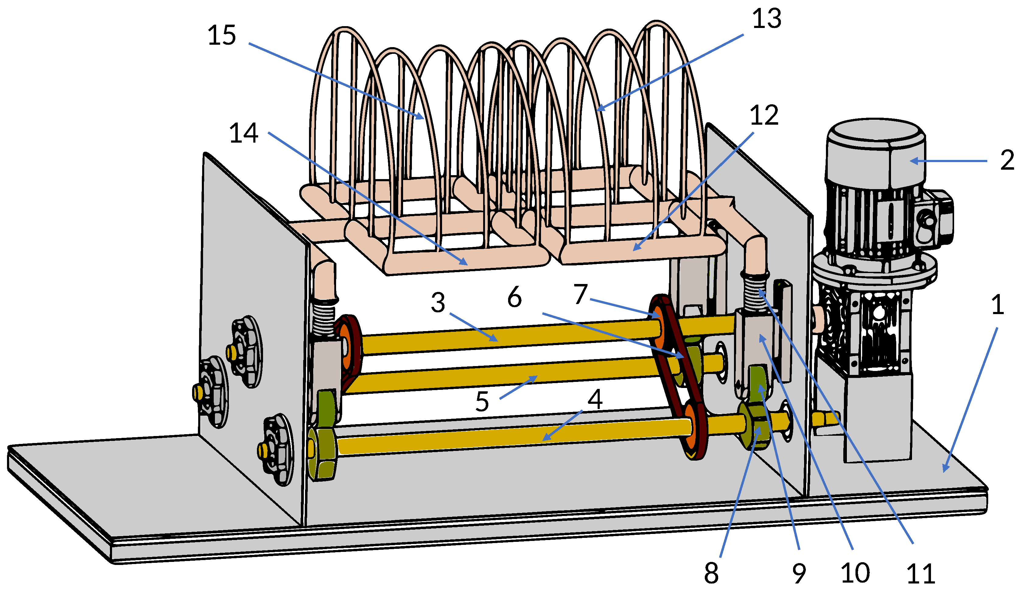
We developed a mechanical horse design capable of simulating both shoulder and hip roll movement with a single main motor. We use only one motor since it is essential to make the control system of the horse movement as simple as possible. In addition, minimizing the number of actuators also means reducing costs, making the design affordable. Higher affordability also means higher accessibility for the user;
2.
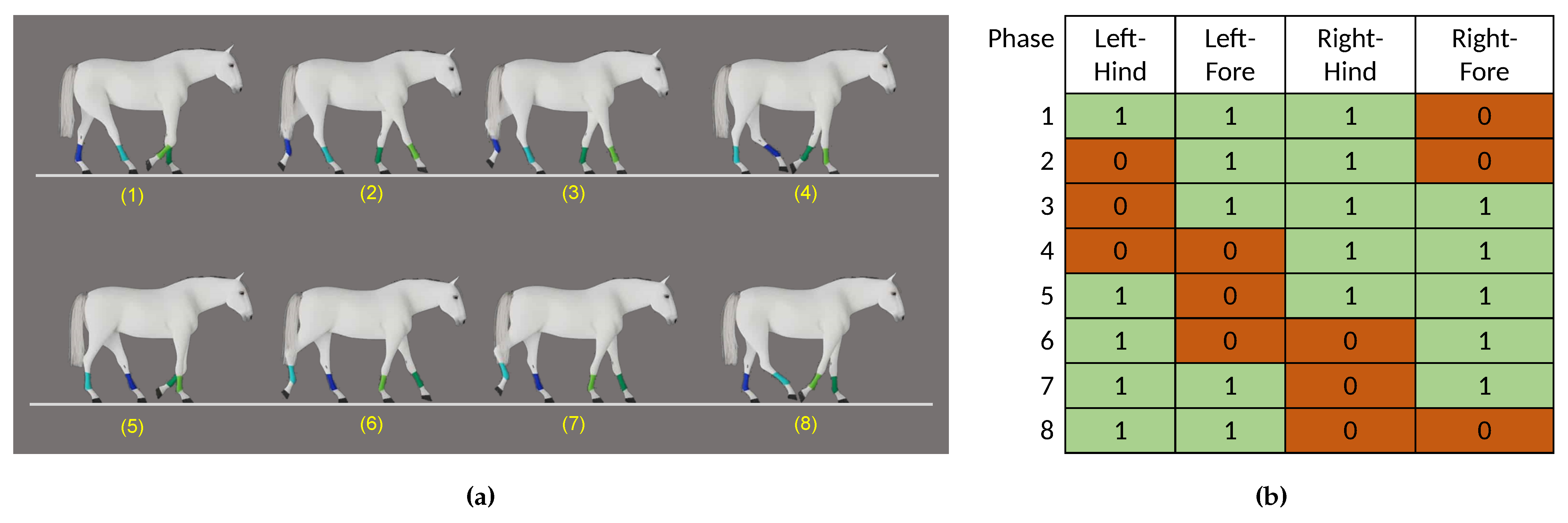
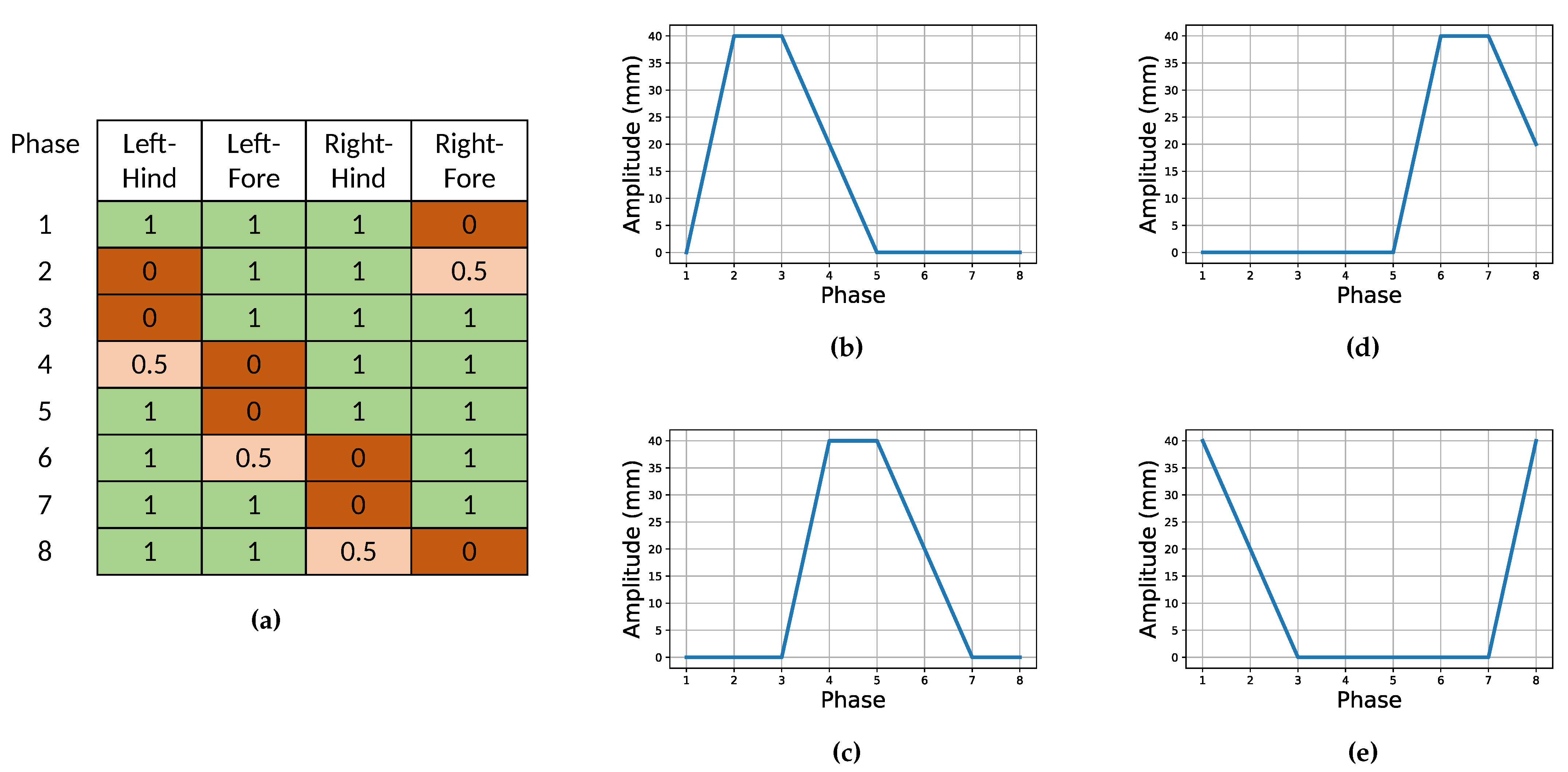
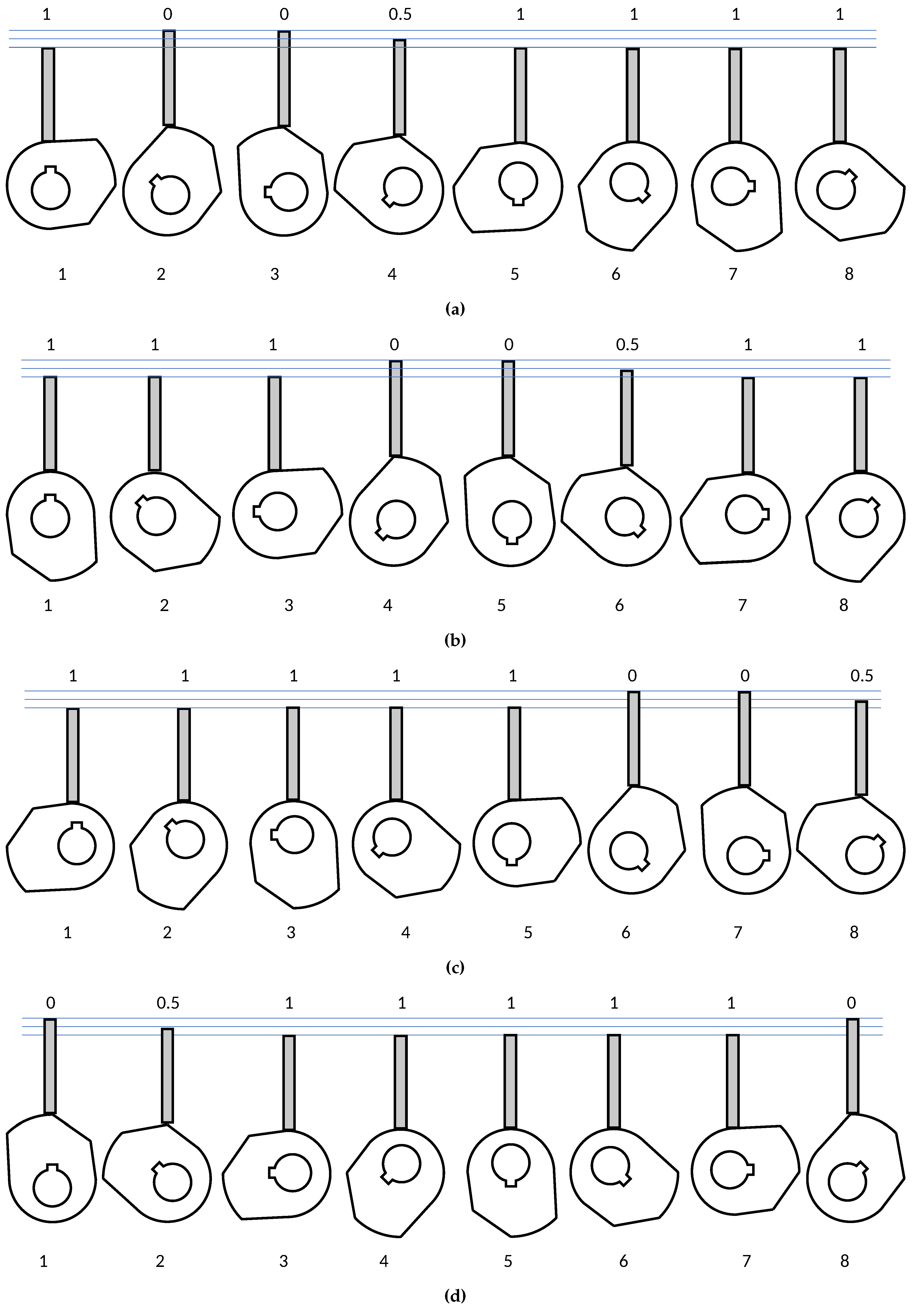
We developed a mechanical horse design capable of simulating both shoulder and hip roll movement where the mechanical horse’s left shoulder, right shoulder, left hip, and right hip have different cyclic motion phases. We argue that this difference is important to create a dual frequency of the sinusoidal curve of horse pelvic obliquity pattern [36] where in the normal human walking gait, pelvic obliquity has the same pattern of dual frequency of sinusoidal curve [37,38,39,40];
3.
The user’s gait when riding our mechanical horse closely resembles a human walking gait, which is a desirable gait for CP rehabilitation. We observe and discuss our experiments for comparing the user’s gait when riding the design and walking in Section 5.

3. Horse Movement Observation and Cams-Followers Designs

Horses have four gait types: the walk, trot, canter, and gallop. The walking gait has consistent, cyclical, rhythmical, bilateral, and symmetrical movement [41]. The horse walking gait has a double sinusoidal pelvic obliquity movement pattern similar to humans [36]. In addition, the duration of one cycle of horse walking gait is also similar to the duration of the average human walking gait [28]. Because of these characteristics, the horse walking gait is the most similar to a human walking gait. Therefore, we choose to simulate the horse walking gait in our mechanical horse for therapeutic purposes.
When walking, a horse’s legs follow this sequence: right-fore, left-hind, left-fore, and right-hind. There are always two or three feet on the ground at a time with 3-2-3-2-3-2-3-2 patterns [42,43]. Figure 1 illustrates a horse’s walking cycle and the representation table of each horse’s legs. The notation “0” represents the foot lifted from the ground, while the notation “1” represents the foot on the ground.
In our design, we want to use cams and followers to simulate the movements of a horse’s legs. The followers act as the horse’s legs. In that respect, we can also interpret the representation table in Figure 1 as the following: each column of the representation table represents linear movements of a follower: “0” represents the follower moving up, while “1” represents the follower moving down.
We also consider that a sudden change from the follower from the “0” position to the “1” position will cause a jerk movement that will cause the rider to feel uncomfortable. We introduce a half movement between them with a “0.5” notation to reduce this effect. Therefore, we will have each cam with three different circles, starting from the smallest to largest: base circle, prime circle, and pitch circle.
The cam circles’ dimensions correspond to the amplitude of the horse’s legs’ linear up and down movements. Yamaguchi [29] uses 45 mm as the amplitude of the forelegs and 35 mm for the hindlegs, while Lee [31] uses 40 mm amplitude for both forelegs and hindlegs. We decided to use 40 mm for our designs through trial and error experiments. This amplitude also resembles a human walking gait [28]. The amplitude translates to the radius difference between the base circle and the pitch circle of 40 mm. We designed the cams to have radii of 35 mm, 55 mm, and 75 mm, respectively.
Figure 2 shows the modified representation table, which accommodates the followers’ half-movements and the desired linear amplitudes movements. This representation table is the base of our cams’ shape designs.
We transform the representation table into a polar coordinate system. We defined phases 1 to 8 as 0 to 315 degrees, respectively. The increment between the phase is 45 . We put the “0” or when the horse’s leg is lifted at the cam’s pitch circle with a 75 mm radius, “1” or when the leg is on the ground at the base circle with a 35 mm radius, and “0.5” at the prime circle with 55 mm radius. The polar coordinate transformation for each leg and how the shape of the cam is designed is illustrated in Figure 3, while Figure 4 shows how the rotating cams translate into the desired linear movements of the followers.

4. System Design, Build, and Assembly

4.1. System Block Diagram—Legs Mechanism

To achieve higher affordability and ease of speed control, we design our mechanical horse only to use a motor as its actuator. The electric motor we use is Motovario’s 080 Size S-series. Connecting four sets of cam and follower to one electric motor is challenging. We solve the problem by introducing central, left, and right shafts with two sets of chains and sprockets into the system. The left and right shafts are responsible for rotating the left and right cam, respectively. A chain and sprocket connect the left and right shafts to the central shaft. The central shaft is connected to the electric motor. Figure 5 explains the block diagram of the system mechanism, while Figure 6 illustrates how we implemented the system mechanism.

4.2. System Block Diagram—Hip and Shoulder Mechanism

We divide the horse body part of our design simulator into two segments: the front and rear body. The division is important since we want to mimic the horse’s shoulder and hip movement simultaneously. We argue that the simulation of shoulder and hip movement is essential to create a dual frequency sinusoidal curve of horse pelvic obliquity pattern, which resembles normal human walking gait [36]. On the other hand, we want the body segment to be capable of supporting a saddle since the saddle has a beneficial effect on the user’s posture [35]. Thus, we only divide the body horse into no more than two parts.
The front body structure is linked to the left and right fore follower, whereas the rear body structure is connected to the left and right hind follower. This configuration enables the front body to have the same cyclic movement but a different phase from the rear body. This movement makes the body twist around the axis, which is the body shaft. We argue that the twisted movement of the body or the same cyclic movement but at a different phase of hip and shoulder movement creates the dual frequency of the sinusoidal curve of the horse pelvic obliquity pattern. Figure 7 shows the block diagram of the system mechanism with the body structure, while Figure 8 illustrates how we implement the body structure to the system mechanism.

4.3. Packaging and Saddle Designs

Figure 9 shows our packaging design: front box, rear box, body enclosing, and saddle. The safety factor is the first consideration for the packaging design. We want to ensure that all moving mechanical and electronic parts are inaccessible to the user when the system is operating. We built the front box to enclose the power supply, controller, electronics part, and left-fore follower and right-fore follower. The rear box encloses the electric motor, left hind, and right hind follower. The box height is parallel to the body height to minimize falling risk.
There are three buttons to control the movement of the mechanical horse. The upper button is the power button to turn off/on the device, the lower right button is the manual speed control switch, and the lower left button is the manual or automatic speed control switch mode button.
We use an inverter, Mitsubishi fr-e720-0.75k, as our motor control device. The inverter input is 0–5 Volt DC. An input of 0 V will produce 0% of the maximum rotation speed of the motor. Conversely, a 5 V input will produce a 100% of the maximum rotation speed, which is 1400 RPM. We have two pre-set speeds: “low” and “high,” which are all the specified variables listed in Figure 10. A gearbox is also used to lower the motor speed to the 60 and 120 RPM desired central shaft speed.
In future research, we want to control the speed through a computer since we want to integrate the mechanical horse with our previously-designed exergaming software [26]. This manual control of the horse’s speed can be done by inputting a specified voltage to the inverter of the control unit.
We covered all packaging parts with 1 cm thick foam and synthetic leather. This can reduce the impact severity and has electrical isolation properties to minimize the electrocution risk. It also creates a luxury image in the user’s perception. We also chose the color blue to evoke the feeling of trust, whereas the black color can cover up any uncleanliness.
For the saddle, we used an actual saddle. The saddle uses synthetic leather and has a handlebar in the front. We bought the smallest saddle as we designed our mechanical horse for children. The saddle is tied to the body structure by wrappingaround the saddle’s belt. This setup is similar to how the saddle is tied to an actual horse.

4.4. Building and Trials

We assemble all the parts, including the customized and store-bought parts, in our industrial partner’s warehouse. Figure 11 shows our team members and child trying the mechanical horse. They experienced the mechanical horse’s movement as being similar to the actual horse. One of our team member’s child (a healthy child) tried the mechanical horse. He seemed relaxed while riding the mechanical horse. However, he criticized that the mechanical horse did not have a head.
The mechanical horse user target base is 3 to 18 years old and under 100 kg. However, for safety reasons, the mechanical horse is designed to be able to support a maximum of 150 kg weight. This safety requirement is to satisfy the Indonesian National Standards (SNI 1727-2020) that a structure must be able to withstand at least 1.4 times the stated maximum weight. Both children and adults can use the mechanical horse. However, the saddle size must be adjusted since the existing saddle is designed for children. The weight of the mechanical horse is around 100 kg. The weight helps stabilize the mechanical horse when in use.

5. Observations and Performance Evaluations

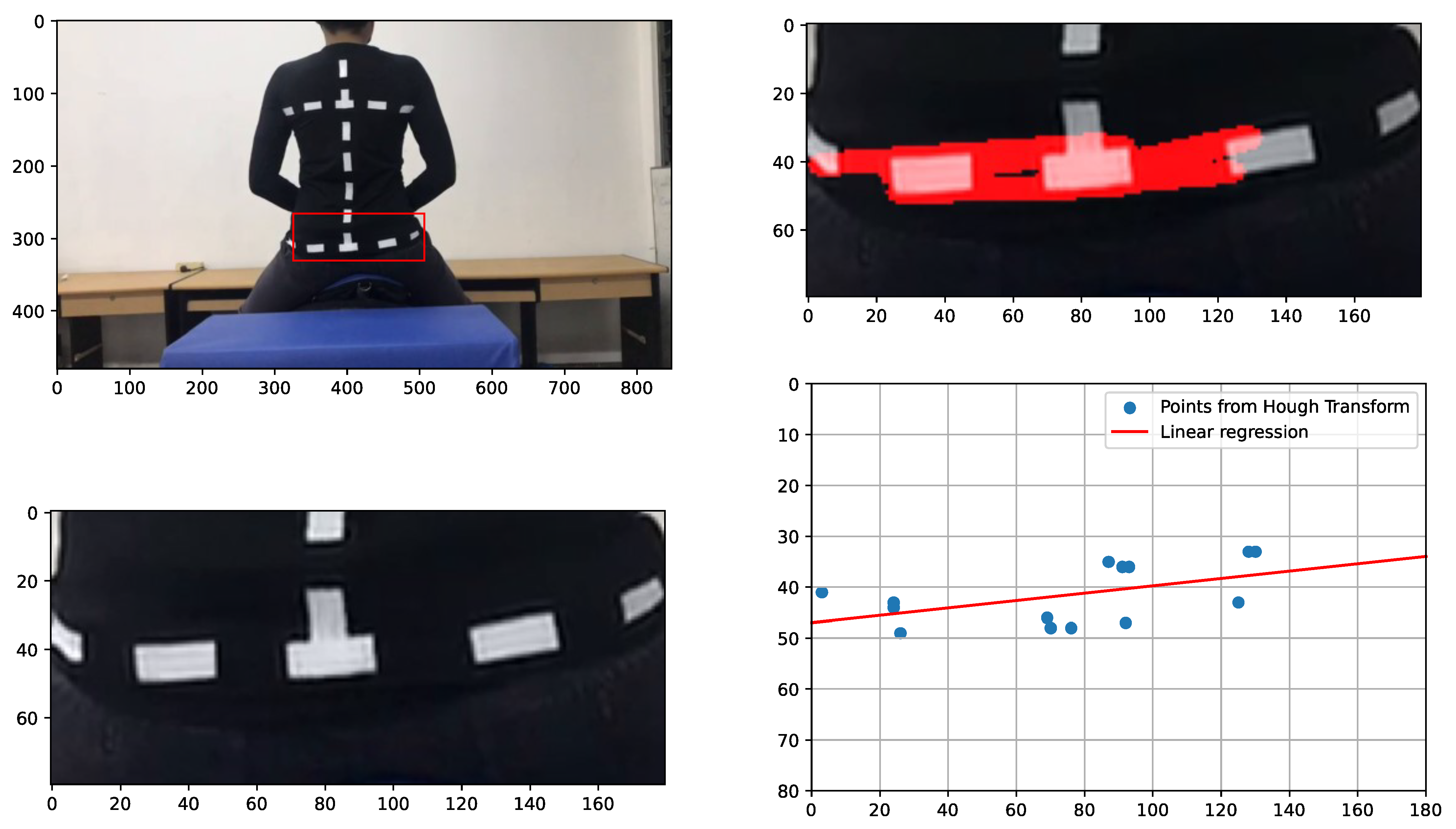
5.1. Data Acquisitions

To compare how similar the user’s riding and walking gait is, We use video and image processing analysis similar to Ref. [28]. We recorded a video of the user’s movements from the back. The first video is when the user is riding our mechanical horse design, while the second video is when the user is walking on a treadmill. We asked the user to wear a black-colored measurement uniform with white dashed lines to make it easy for us to process the data. Figure 12 shows a user riding our mechanical horse and the same user walking on a treadmill using the same uniform.
To measure the pelvic tilt angles, we extracted every frame from the video and cropped the pelvic part of the image. We then used the Hough Transform [44] to detect the dashed white lines of the user’s pelvis. We then extracted the points of the vertex of the resulting lines to a coordinate and performed linear regression to the set of points, in which we got the slope and intercept of the line.
y = m x + c
where m and c are the slope and intercept, respectively. The inverse tangent of the slope in degrees will be the approximate angle of the pelvic tilt, p.
p = arctan ( m ) × 180 2 π
Figure 13 illustrates how we obtain the pelvic tilt angles from one frame. We then iterate the process throughout the frames and save all the pelvic tilt angles obtained as an array of p, which we denote as p . We name the data from the riding video as p r and from the walking video as p w . However, the data obtained from the video is not clean but still resembles the desired sinusoidal-like signals in general. To reduce the noise effect, we smooth the data using Savitzky–Golay filter [45] with a window of w = 31 . We call the resulting series as p ^ r and p ^ w . Figure 14 shows (a) p r and p ^ r (b) p w and p ^ w , and (c) comparison between p ^ r and p ^ w with the walking frequency adjusted to the riding frequency.
In the analysis of the comparison between the two signals, we only focus on the shape and the amplitude of both pelvic tilt angles. The riding frequency can easily be adjusted by controlling the main motor rotational speed.

5.2. Performance Evaluations

From Figure 14, we can compare our data for some factors: shape, amplitude, the slope between peaks and troughs, and the smoothness of the curve. Our observations are as follows:
1.
The shape of both data looks very similar, with a slight difference: the walking data closely resembles a sinusoidal function, while the peak of riding our design is not precisely sinusoidal but more of a triangular shape;
2.
The amplitude of the pelvic tilt angles is also similar between both of them, which is about 5 to 6 degrees in up and down directions;
3.
The slope between the peaks and troughs of each cycle is also similar to each other;
4.
The curve is smooth while walking but has some noticeable notches when going up and down. These notches may be caused by the sudden jerk movements caused by the transition of the followers.
From our observations, we conclude that our mechanical horse provides a similar gait to a healthy user when walking, making it suitable for hippotherapy for CP rehabilitation. We can also adjust the rotational speed of the motor to adjust the frequency of the riding gait, simulating a faster or slower walking gait.

6. Discussion and Future Plans

6.1. Improvements Opportunities

We presented our design from our observations of a horse walking cycle. We then derived it into motor and cam-follower mechanisms. The two-bodied structure segments can generate two different phases of movement between the front and rear parts, resembling a horse’s shoulder and hip. From the data available, we conclude that our design is capable of simulating a normal human walking gait.
However, we are aware that many improvements can be applied to our design. Some of the design-improvements ideas that we got during our implementation, assembly, manufacturing, and trial process are:
1.
Our HRS’s size and weight is relatively bulky compared to other mechanical horses’ design, especially compared to the store-bought HRS;
2.
For safety reasons, a body weight support device might be necessary to minimize the falling risk, especially when the device is intended for children with CP.

6.2. Future Research and Developments Plan

For future developments, we want to invest in proper motion detection equipment to accurately measure how similar the walking gait is compared to riding our design. Using the proper equipment, we can measure the pelvic obliquity angles and other necessary variables.
We are currently working on proposing the device to comply with the National Standard of Indonesia (SNI) for electromedical devices. After passing the compliance, we can proceed to a clinical trial for the device’s effectiveness in an actual hippotherapy setting.
One of the main factors that lead to a therapy’s success is the patient’s motivation. We are aware that motivational factors such as the scenery, the relation between the horse and the patients, and many others are missing in a room setting. Therefore, in our previous research, we developed a virtual environment and a game to motivate the patients. Therefore, in future research, we want to integrate the device with our previous exergaming software [26]. Currently, the user can only control the in-game horse speed and movements. In the future, we want to make the mechanical horse’s speed increase when the user increases the in-game horse’s speed.
Another interesting research possible is to compare hippotherapy, either with an actual horse or a simulator, to classical means of therapy such as walking on the treadmill, where a subjective test to actual patients will be conducted.

7. Conclusions

This report presented an engineering design of a horse riding simulator (HRS) or mechanical horse for CP rehabilitation purposes. Our design also has advantages compared to other mechanical horses:
1.
Only uses one motor as the sole actuator, minimizing costs and power consumption. This is achieved by designing unique cams and followers mechanism that simulates actual horse movements;
2.
Provides different movement phases between the shoulder and hip, mimicking actual horse body movements;
3.
An actual horse saddle can be installed, which is beneficial to the user’s posture [35];
4.
The design is capable of simulating a human walking gait, as proven by our experiment using video analysis.
We also know that our design has much room for improvement. One of them is reducing the weight of our design to ease the device’s mobility. Another improvement is installing safety measures such as a harness or weight support, especially when the device is intended for children with CP.
We also plan to integrate our mechanical design into our exergaming software project so that the user can control both the in-game horse and the mechanical horse. More importantly, we are also working on the design to comply with the Indonesian National Standard (SNI) so that our device can go through clinical trials with actual CP patients.

Author Contributions

This work was realized through the collaboration of all authors. Conceptualization, A.S., W.T., S.S.R., N.P., M.C.S. and E.S.; methodology, A.S., W.T. and S.S.R.; software, N.P. and W.T.; investigation, W.T. and A.S.; resources, W.T., C.S.; data curation, A.S. and C.S.; writing—original draft preparation, W.T. and A.S.; writing—review and editing, A.S.; visualization, A.S. and M.O.H.; supervision, C.S. and E.S.; project administration, W.T. and C.S.; funding acquisition, W.T., A.S., M.O.H. and C.S. All authors have read and agreed to the published version of the manuscript.

Funding

This research was funded by Lembaga Pengembangan Inovasi dan Kewirausahaan, Institut Teknologi Bandung (LPIK ITB) under the grant “Program Penguatan Inovasi 2021” number 289L/IT1.A/SK-KP/2021 and partly by School of Electrical Engineering, Telkom University.

Informed Consent Statement

Informed consent was obtained from all subjects involved in the study.

Data Availability Statement

Not applicable.

Acknowledgments

We thank Nurseptian Pratomo and PT. Monta Cakra Teknologi for helping us with the technical support for the design, implementation, manufacturing, and assembly of the horse riding simulator.

Conflicts of Interest

The authors declare no conflict of interest.

Abbreviations

The following abbreviations are used in this manuscript:
CPCerebral Palsy
HRSHorse Riding Simulator

References

  1. Rosenbaum, P.; Paneth, N.; Leviton, A.; Goldstein, M.; Bax, M.; Damiano, D.; Dan, B.; Jacobsson, B. A report: The definition and classification of cerebral palsy April 2006. Dev. Med. Child Neurol. Suppl. 2007, 109, 8–14. [Google Scholar] [CrossRef] [PubMed]
  2. Wright, F.V.; Rosenbaum, P.L.; Goldsmith, C.H.; Law, M.; Fehlings, D.L. How do changes in body functions and structures, activity, and participation relate in children with cerebral palsy? Dev. Med. Child Neurol. 2008, 50, 283–289. [Google Scholar] [CrossRef] [PubMed]
  3. Beckung, E.; Carlsson, G.; Carlsdotter, S.; Uvebrant, P. The natural history of gross motor development in children with cerebral palsy aged 1 to 15 years. Dev. Med. Child Neurol. 2007, 49, 751–756. [Google Scholar] [CrossRef]
  4. Koca, T.T.; Ataseven, H. What is hippotherapy? The indications and effectiveness of hippotherapy. North. Clin. Istanb. 2015, 2, 247. [Google Scholar] [CrossRef] [PubMed]
  5. Pantera, E.; Froment, P.; Vernay, D. Does Hippotherapy Improve the Functions in Children with Cerebral Palsy? Systematic Review Based on the International Classification of Functioning. J. Integr. Complement. Med. 2022. [Google Scholar] [CrossRef] [PubMed]
  6. Scott, N. Special Needs, Special Horses: A Guide to the Benefits of Therapeutic Riding; Number 4; University of North Texas Press: Denton, TX, USA, 2005. [Google Scholar]
  7. Moenardi, M.C.S.; Sungkar, E.; Hawani, D. Cerebral Palsy Parents’ Knowledge, Attitude, and Behavior at Dr. Hasan Sadikin General Hospital Bandung 2014. Althea Med. J. 2020, 7, 84–88. [Google Scholar] [CrossRef]
  8. Setyawan, A.; Mirajziana, K.; Husein, W.F. Terapi Berkuda (Hippotherapy) Sebagai Media Stabilisasi Emosi Penyandang Autisme. 2010. Available online: https://repository.ipb.ac.id/handle/123456789/44472 (accessed on 1 November 2022).
  9. Herrero, P.; Asensio, A.; Garcia, E.; Marco, A.; Olivan, B.; Ibarz, A.; Gomez-Trullen, E.M.; Casas, R. Study of the therapeutic effects of an advanced hippotherapy simulator in children with cerebral palsy: A randomised controlled trial. BMC Musculoskelet. Disord. 2010, 11, 1–6. [Google Scholar] [CrossRef] [PubMed] [Green Version]
  10. de Lima Mello, E.M.C.; de Lima, M.B.B.; Prieto, A.V.; Alves, F.M.; Bento, A.C.C.; Benedita, L.; Oliveira, S.; Blascovi-Assis, S.M. Effects of a JOBA horse riding simulator on postural balance in children with spastic cerebral palsy. Int. J. Dev. Res. 2011, 11, 48621–48624. [Google Scholar] [CrossRef]
  11. Borges, M.B.S.; Werneck, M.J.d.S.; Silva, M.d.L.d.; Gandolfi, L.; Pratesi, R. Therapeutic effects of a horse riding simulator in children with cerebral palsy. Arquivos de Neuro-Psiquiatria 2011, 69, 799–804. [Google Scholar] [CrossRef]
  12. Han, J.Y.; Kim, J.M.; Kim, S.K.; Chung, J.S.; Lee, H.C.; Lim, J.K.; Lee, J.; Park, K.Y. Therapeutic effects of mechanical horseback riding on gait and balance ability in stroke patients. Ann. Rehabil. Med. 2012, 36, 762–769. [Google Scholar] [CrossRef]
  13. Park, J.; Lee, S.; Lee, J.; Lee, D. The effects of horseback riding simulator exercise on postural balance of chronic stroke patients. J. Phys. Ther. Sci. 2013, 25, 1169–1172. [Google Scholar] [CrossRef] [PubMed] [Green Version]
  14. Choi, H.J.; Kim, K.J.; Nam, K.W. The effects of a horseback riding simulation exercise on the spinal alignment of children with cerebral palsy. J. Korean Phys. Ther. 2014, 26, 209–215. [Google Scholar]
  15. Lee, C.w.; Kim, S.G.; Na, S.S. The effects of hippotherapy and a horse riding simulator on the balance of children with cerebral palsy. J. Phys. Ther. Sci. 2014, 26, 423–425. [Google Scholar] [CrossRef] [PubMed] [Green Version]
  16. Lee, D.; Lee, S.; Park, J. Effects of indoor horseback riding and virtual reality exercises on the dynamic balance ability of normal healthy adults. J. Phys. Ther. Sci. 2014, 26, 1903–1905. [Google Scholar] [CrossRef] [PubMed] [Green Version]
  17. Cho, W.S.; Cho, S.H. Effects of mechanical horseback riding exercise on static balance of patient with chronic stroke. J. Korea Acad.-Ind. Coop. Soc. 2015, 16, 1981–1988. [Google Scholar] [CrossRef] [Green Version]
  18. Temcharoensuk, P.; Lekskulchai, R.; Akamanon, C.; Ritruechai, P.A.; Ongsa, S.S. Effect of horseback riding versus a dynamic and static horse riding simulator on sitting ability of children with cerebral palsy: A randomized controlled trial. J. Phys. Ther. Sci. 2015, 27, 273–277. [Google Scholar] [CrossRef] [Green Version]
  19. Cha, Y.J.; Stanley, M.; Shurtleff, T.; You, J.S.H. Long-term effects of robotic hippotherapy on dynamic postural stability in cerebral palsy. Comput. Assist. Surg. 2016, 21, 111–115. [Google Scholar] [CrossRef] [Green Version]
  20. Kim, M.J.; Kim, T.Y.; Oh, S.; Yoon, B.C. Equine Exercise in Younger and Older Adults: Simulated Versus Real Horseback Riding. Percept. Mot. Ski. 2018, 125, 93–108. [Google Scholar] [CrossRef] [Green Version]
  21. Park, J.H.; You, J.S.H. Innovative robotic hippotherapy improves postural muscle size and postural stability during the quiet stance and gait initiation in a child with cerebral palsy: A single case study. NeuroRehabilitation 2018, 42, 247–253. [Google Scholar] [CrossRef]
  22. Kim, H.W.; Nam, K.S.; Son, S.M. Effects of Virtual Reality Horse Riding Simulator Training Using a Head-Mounted Display on Balance and Gait Functions in Children with Cerebral Palsy: A Preliminary Pilot Study. J. Korean Phys. Ther. 2019, 31, 273–278. [Google Scholar] [CrossRef]
  23. Hemachithra, C.; Meena, N.; Ramanathan, R.; Felix, A.J.W. Immediate effect of horse riding simulator on adductor spasticity in children with cerebral palsy: A randomized controlled trial. Physiother. Res. Int. 2020, 25, e1809. [Google Scholar] [CrossRef] [PubMed]
  24. Chinniah, H.; Natarajan, M.; Ramanathan, R.; Ambrose, J.W.F. Effects of horse riding simulator on sitting motor function in children with spastic cerebral palsy. Physiother. Res. Int. 2020, 25, e1870. [Google Scholar] [CrossRef] [PubMed]
  25. Jung, Y.G.; Chang, H.J.; Jo, E.S.; Kim, D.H. The Effect of a Horse-Riding Simulator with Virtual Reality on Gross Motor Function and Body Composition of Children with Cerebral Palsy: Preliminary Study. Sensors 2022, 22, 2903. [Google Scholar] [CrossRef] [PubMed]
  26. Satriawan, A.; Trusaji, W.; Hasanuddin, M.O.; Rahadini, S.S.; Selekta, M.C.; Sungkar, E. Design of Virtual Reality-Based Hippotherapy Simulator Exergaming Software and Its Controller for Rehabilitation of Children with Cerebral Palsy in Indonesia: An Engineering Concept. Designs 2022, 6, 76. [Google Scholar] [CrossRef]
  27. Park, J.H.; Shurtleff, T.; Engsberg, J.; Rafferty, S.; You, J.Y.; You, I.Y.; You, S.H. Comparison between the robo-horse and real horse movements for hippotherapy. Bio-Med. Mater. Eng. 2014, 24, 2603–2610. [Google Scholar] [CrossRef] [Green Version]
  28. Garner, B.A.; Rigby, B.R. Human pelvis motions when walking and when riding a therapeutic horse. Hum. Mov. Sci. 2015, 39, 121–137. [Google Scholar] [CrossRef]
  29. Yamaguchi, M.; Iguchi, N. Development of a horseback riding simulator. Adv. Robot. 1991, 6, 517–528. [Google Scholar] [CrossRef]
  30. Lott, J. A Mechanized Horseback Riding Simulator as an Aid to Physical Therapy. 2006. Available online: https://digitalcommons.usf.edu/etd/3752/ (accessed on 1 November 2022).
  31. Lee, W.; So, B.R.; Lee, Y.; Moon, C. A new robotic horseback-riding simulator for riding lessons and equine-assisted therapy. Int. J. Adv. Robot. Syst. 2018, 15, 1729881418784433. [Google Scholar] [CrossRef] [Green Version]
  32. Benoit, H.D.; Garner, B.A. Designing, Constructing, and Testing a Second-Generation Prototype Mechanical Hippotherapy Horse. 2011. Available online: https://baylor-ir.tdl.org/handle/2104/8200 (accessed on 1 November 2022).
  33. Montgomery, M. Development and Validation of a Robust, Adjustable Hippotherapy Simulator. 2015. Available online: https://scholar.rose-hulman.edu/abbe_grad_theses/7/ (accessed on 1 November 2022).
  34. Montgomery, M.J. Hippotherapy Device. U.S. Patent US10960267B2, 30 March 2021. Available online: https://patents.google.com/patent/US10960267B2/en (accessed on 1 November 2022).
  35. Greve, L.; Dyson, S. The horse–saddle–rider interaction. Vet. J. 2013, 195, 275–281. [Google Scholar] [CrossRef]
  36. MacPhail, H.A.; Edwards, J.; Golding, J.; Miller, K.; Mosier, C.; Zwiers, T. Trunk Postural Reactions in Children with and without Cerebral Palsy during Therapeutic Horseback Riding. 1998. Available online: https://journals.lww.com/pedpt/abstract/1998/01040/trunk_postural_reactions_in_children_with_and.2.aspx (accessed on 1 November 2022).
  37. Lewis, C.L.; Laudicina, N.M.; Khuu, A.; Loverro, K.L. The human pelvis: Variation in structure and function during gait. Anat. Rec. 2017, 300, 633–642. [Google Scholar] [CrossRef] [Green Version]
  38. Forczek, W.; Ivanenko, Y.; Salamaga, M.; Sylos-Labini, F.; Frączek, B.; Masłoń, A.; Curyło, M.; Suder, A. Pelvic movements during walking throughout gestation-the relationship between morphology and kinematic parameters. Clin. Biomech. 2020, 71, 146–151. [Google Scholar] [CrossRef] [PubMed]
  39. Michaud, S.B.; Gard, S.A.; Childress, D.S. A Preliminary Investigation of Pelvic Obliquity Patterns during Gait in Persons with Transtibial and Transfemoral Amputation. 2000. Available online: https://pubmed.ncbi.nlm.nih.gov/10847567/ (accessed on 1 November 2022).
  40. Bolink, S.A.; Brunton, L.R.; van Laarhoven, S.; Lipperts, M.; Heyligers, I.C.; Blom, A.W.; Grimm, B. Frontal plane pelvic motion during gait captures hip osteoarthritis related disability. Hip Int. 2015, 25, 413–419. [Google Scholar] [CrossRef] [PubMed] [Green Version]
  41. Lightsey, P.; Lee, Y.; Krenek, N.; Hur, P. Physical therapy treatments incorporating equine movement: A pilot study exploring interactions between children with cerebral palsy and the horse. J. Neuroeng. Rehabil. 2021, 18, 1–11. [Google Scholar] [CrossRef] [PubMed]
  42. Harris, S.E. Horse Gaits, Balance, and Movement: The Natural Mechanics of Movement Common to All Breeds; Souvenir Press: London, UK, 2017. [Google Scholar]
  43. Luso Maria. The 4 Basic Horse Gaits Explained [Diagrams & Animations]. 2020. Available online: https://www.horsesandus.com/the-4-basic-horse-gaits-explained/ (accessed on 1 November 2022).
  44. Mukhopadhyay, P.; Chaudhuri, B.B. A survey of Hough Transform. Pattern Recognit. 2015, 48, 993–1010. [Google Scholar] [CrossRef]
  45. Schafer, R.W. What is a Savitzky-Golay filter? [lecture notes]. IEEE Signal Process. Mag. 2011, 28, 111–117. [Google Scholar] [CrossRef]
Figure 1. A horse’s walking cycle. (a) Illustration of a horse’s walking gait cycle. (b) A representation table of each leg of a horse, “0” when the leg is lifted from the ground, while “1” is when the leg is on the ground. Figures used with permission from Ref. [43].
Machines 10 01060 g001
Figure 2. (a) A slightly modified version of the horse’s legs model changing “0” to “0.5” when the horse puts down its leg to prevent a sudden jerk movement going down and desired linear motion of (b) left-hind leg, (c) left-fore leg, (d) right-hind leg, and (e) right-fore leg.
Machines 10 01060 g002
Figure 3. Cam design of each leg of the horse: (a) Left-fore, (b) Left-hind, (c) Right-fore, (d) Right-hind. Phase 1 corresponds to 0 and increases 45 clockwise until 315 , which corresponds to phase 8. The notations “0”, “0.5”, and “1” in each leg correspond to a point at the pitch circle, prime circle, and base circle of the cams.
Machines 10 01060 g003
Figure 4. Illustration of how a counter-clockwise rotating cam generates a cycle of a follower’s linear movements replicating each leg of a horse: (a) left-hind, (b) left-fore, (c) right-hind, (d) right-fore.
Machines 10 01060 g004
Figure 5. Block diagram of the designed system mechanism to generate linear movements of each horse’s legs.
Machines 10 01060 g005
Figure 6. System mechanism: an electric motor rotates a central shaft (a), then transfers its rotation by the front (b) and rear (c) chain-sprocket system to the right (d) and left (e) shafts. It then rotates the right-fore (f), left-fore (g), right-hind (h), left-hind (i) cams. It then generates linear movements that simulate a horse’s legs in the followers (j), (k), (l), and (m).
Machines 10 01060 g006
Figure 7. Complete block diagram of our designed HRS device with the front body structure and frame simulating a horse’s shoulder and the back ones simulating a horse’s hip.
Machines 10 01060 g007
Figure 8. Complete view of our design before packaging: (1) base structure, (2) electric motor, (3) central shaft, (4) left shaft, (5) right shaft, (6) chains, (7) sprockets, (8) cams, (9) roller, (10) follower, (11) compression springs, (12) rear body structure, (13) rear body frame, (14) front body structure, (15) front body frame, and (16) body shaft.
Machines 10 01060 g008
Figure 9. Packaging design of our HRS device. The front box part is for putting power supplies, controllers, and all electronic parts. The rear box is for putting the main electric motor.
Machines 10 01060 g009
Figure 10. Control unit system diagram block and the value of the pre-set speed variables.
Machines 10 01060 g010
Figure 11. Various age ranges of users that tried our design.
Machines 10 01060 g011
Figure 12. Video snapshot of a user wearing the measurement uniform: (a) Riding the mechanical horse and (b) walking on a treadmill.
Machines 10 01060 g012
Figure 13. Pelvic tilt angle data acquisitions from the videos: (1) We extract all the frames from the video, (2) we crop the pelvic part from the video frame, (3) we use Hough transform to detect lines of the measuring clothes, and (4) we extract points from all the detected lines, and then perform a linear regression. The inverse tangent of the linear regression results’ slope is the approximate pelvic tilt angles of the users. We repeat this process for every frame in the videos.
Machines 10 01060 g013
Figure 14. Time plot of the comparison of pelvic tilt angles between (a) a user when riding our design vs. (b) the user walking, adjusted to the same frequency, both filtered using the Savitzky–Golay filter [45]. Subfigure (c) shows the comparison plot between them.
Machines 10 01060 g014
Table 1. Comparison of store-bought and researcher-designed HRS devices.
VariablesPanasonic JOBA [9,10,11,12,14,16,22]Daewon Fortis [13,17,19,20,21]OSIM uGallop [18,23,24]SRIDER [15]/ Shinhwa [25]/ JUFIT [26]Yamaguchi [29]Lott [30]Lee [31]Benoit [32]Montgomery [33]Our Design
Horse GaitSide to side workout, forward and backward tilt waistGallopGallopGallopWalk, trot, canterWalk, trot, canterWalk, trot, canter, gallopWalkWalkWalk, modified to replicate a human’s walking gait
MechanismsUnknownUnknownUnknownUnknownLinear actuatorLinear actuatorLinear actuator and rotation moduleLinear actuator (Stewart platform)Cams and followers, with different front and rear sizesCams and Followers
Number of ActuatorsUnknownUnknownUnknownUnknown2: Foreleg and hindleg2: Horizontal and vertical4: Left-fore, left-hind, right-fore, right-hind6 Stewart platform actuator1 motor and 4 cams and followers1 motor and 4 cams and followers
Horse Body Segments111111, a foam can be added to simulate flexion-extension11Eight flexible rib segments2: shoulder and hip
MovementsUp, down, forward, backward, pitch, and rollUp, down, forward, backward, and pitchPitch and rollUp, down, forward, backwardUp, down, forward, backwardUp, down, forward, backward, and pitchx, y, z, roll, pitch, and yawx, y, z, roll, pitch, and yawMimic hip and shoulder motions of a walking horseMimic hip and shoulder motions of a walking horse
SaddleSaddle-shaped seatSaddle-shaped seatSaddle-shaped seatSaddle-shaped seatSaddle can be attachedSaddle can be attachedNo saddleNo saddleNo saddleUsing actual horse saddle
Other remarksSpecifically designed as an exercise deviceSpecifically designed as an exercise deviceSpecifically designed as an exercise deviceSpecifically designed as an exercise device, the speed is too fast, even for the lowest settingsNo roll motion that important to mimic a walking horseNo roll motion and only has 1 horse body segmentsOnly has 1 horse body segments, while a walking horse has different roll phase between fore-legs and hind-legsOnly has 1 horse body segments, while a walking horse has different roll phase between fore-legs and hind-legsAlthough the design is mimicking the flexion of horseback, the size is not to scale. The ribs also can be a pinch point hazard to the fingers of children users.Mimic the motion of a horse’s hip and shoulder with a similar size to accommodate an actual horse saddle
Publisher’s Note: MDPI stays neutral with regard to jurisdictional claims in published maps and institutional affiliations.

