Abstract
Based on the direct differentiation method, sensitivity analysis of transient responses with respect to local nonlinearity is developed in this paper. Solutions of nonlinear equations and time-domain integration are combined to compute the response sensitivities, which consist of three steps: firstly, the nonlinear differential equations of motion are solved using Newton–Raphson iteration to obtain the transient response; secondly, the algebraic equations of the sensitivity are obtained by differentiating the incremental equation of motion with respect to nonlinear coefficients; thirdly, the nonlinear transient response sensitivities are determined using the Newmark-β integration in the interested time range. Three validation studies, including a Duffing oscillator, a nonlinear multiple-degrees-of-freedom (MDOF) system, and a cantilever beam with local nonlinearity, are adopted to illustrate the application of the proposed method. The comparisons among the finite difference method (FDM), the Poincaré method (PCM), the Lindstedt–Poincaré method (LPM), and the proposed method are conducted. The key factors, such as the parameter perturbation step size, the secular term, and the time step, are discussed to verify the accuracy and efficiency. Results show that parameter perturbation selection in the FDM sensitivity analysis is related to the nonlinear features depending on the initial condition; the consistency of the transient response sensitivity can be improved based on the accurate nonlinear response when a small time step is adopted in the proposed method.
1. Introduction
A mathematical model (for example, in biomedical science [1], environmental science [2], or engineering) can be highly complex in analyzing the behavior of the system and, as a result, its relationships between inputs and outputs may be difficult to understand. In models consisting of some parameters, sensitivity analysis is an essential component of model building and accuracy assurance [3]. Sensitivity analysis methods can be classified by determining whether they search the input space at a point or over a larger region of it, namely, global methods and local methods. The former ones take the sensitivities at multiple points, e.g., the Sobol method [4], that represent the influence of the inputs on the output uncertainty. The local methods generate the sensitivity of the model inputs at a specific input point. The simplicity of the local methods ensures their popularity to structural engineering application, e.g., structural optimization [5] and model updating [6]. However, without considering structural nonlinearity [7,8], the structural responses will be calculated with low accuracy; essential errors are even introduced into the response. In order to determine the rate of change of structural response caused by perturbation in parameters, sensitivity analysis considering localized nonlinearity should be paid more attention.
Sensitivity analysis of dynamic responses has been studied extensively. Lu and Law [9] discussed the features of the response sensitivities of the structure when under sinusoidal, impulsive, and random excitations. Weng et al. [10] proposed an efficient approach to calculate the linear dynamic response sensitivities using the dynamic condensation. For the nonlinear response sensitivity analysis, Park et al. [11] developed a procedure to obtain the sensitivity of the nonlinear transient response based on the time finite element method. Choi et al. [12,13] presented a continuum-based sizing design sensitivity analysis method for the transient dynamic response of nonlinear structure with elastic–plastic material and large deformation. Liu et al. [14] developed a sensitivity analysis method for nonlinear transient aeroelastic gust response. In addition, the parameter variations in nonlinear systems are also uncertain, e.g., model form error, initial and boundary conditions, and operation wear [15]. Global sensitivity analysis can be applied to identify the main sources of uncertainty in the model inputs, especially when the model under consideration is nonlinear and the uncertainty level of model inputs is large [16,17]. Therefore, the sensitivity analysis method has been developed to quantitatively analyze the influence between the inputs and outputs of the nonlinear systems.
In general, the sensitivity analysis methods can also be classified by computational algorithms [18]: the analytical method, the finite difference method (FDM), and the semi-analytical method; these methods can also be applied to nonlinear structures. The FDM is easy to be implemented for sensitivity analysis with respect to multiple parameters by performing repeated analyses [19], but the accuracy depends on the parameter perturbations. Another method based on a complex variable derivative can be applied to obtain the sensitivity with second-order accuracy. Wang and Apte [20] proposed the application of a complex variable method for eigenvalue and eigenvector sensitivity analysis. Kim et al. [21] presented a numerical procedure for generating accurate tangent stiffness matrices. Garza and Millwater [22] presented the multicomplex Newmark-β time integration method for transient response sensitivity analysis. In our previous work [23], the nonlinear transient response sensitivities are computed using the real–imaginary perturbations. The imaginary-based sensitivity is feasible for a small imaginary perturbation and the real-based sensitivity is stable within a limited real perturbation range. However, the application of the above perturbation-based sensitivity analysis methods is limited to computational inefficiency caused by repeated analyses.
The derivatives are calculated by using analytical differentiation integrated with finite difference approximation, which is the so-called “semi-analytical” sensitivity method [24]. It might be attractive as it combines the computational efficiency of the analytical method with the ease to implementation. Cho and Kim [25] proposed a refined semi-analytical method to improve the convergence of the eigenvalue and eigenvector sensitivities for a wide range of perturbed size of design variables. Wang et al. [26] applied the secant stiffness matrix to semi-analytical sensitivity analysis for geometrical nonlinear problems. Fernandez and Tortorelli [27] presented a semi-analytical-based sensitivity analysis method for nonlinear transient problems. The wide application of the semi-analytical method to nonlinear transient response sensitivity analysis, however, is limited, owing to the inaccuracy and the computational inefficiency caused by the finite difference approximation.
The analytical differentiation is an accurate method to determine the sensitivity of the structural response. The adjoint variable method (AVM) is well known to perform analytical derivatives [28,29]. Zhu et al. [30] developed the adjoint sensitivity analysis method based on a penalty formulation. Lauss et al. [31] presented the discrete adjoint method to calculate the exact gradient for solving inverse problems. Yan and Cheng [32] applied the adjoint variable method to sensitivity analysis for residual vibrations subject to impact loads. Keulen et al. [24] reviewed and compared some methods for transient response sensitivity analysis. The calculation of the transient response using AVM is difficult to solve simultaneously with response analysis.
The nonlinear transient response sensitivity, on the other hand, can be efficiently calculated by the DDM [33], which is adopted in this study. Considering material nonlinearity, Conte et al. [34] and Gu et al. [35,36] distinguished the similar schemes by using the DDM, (1) differentiate then time discretize and (2) time discretize then differentiate, for transient response sensitivity analysis. The exact differentiation of the discretized equation of motion is employed in the first method. In the second method, the time discretization of the discretized equation of motion is implemented firstly. Then, differentiating with respect to the parameters, the time discrete–spatially discrete equations are determined as an algebraic sensitivity equation. These two approaches will obtain the same results when the same discretization and integration schemes are used to determine numerically both the response and its sensitivities. Ding et al. [37] proposed the design sensitivity analysis method of transient response for non-viscously damped systems based on the DDM. Wojtkiewicz and Johnson [38] presented an efficient method for response sensitivity analysis of a structure with local modification in time domain. In our previous work [39], the DDM-based response sensitivity is applied to update the local nonlinear parameters accurately and efficiently. However, the comparison between the DDM and the perturbation sensitivity analysis method is not investigated. The influencing factors of DDM method for nonlinear system response sensitivity analysis were also not discussed. The major novelty and contributions of this study are concluded as follows:
- ➢
- The transient response sensitivities of a nonlinear structure are analyzed using the DDM method, in which the algebraic equations of the nonlinear transient response sensitivity are derived.
- ➢
- The effect of parameter perturbation step size in FDM sensitivity, and the effect of the secular term and the time step are investigated using three different nonlinear systems.
This paper is organized as follows: the modeling method of local nonlinearity in structure and the general formulation of nonlinear dynamical response and direct differentiation-based sensitivity calculation are introduced in Section 2. Three numerical validations and discussions of transient response sensitivity analysis for a Duffing oscillator, a nonlinear MDOF system, and a cantilever beam with nonlinear spring are conducted in Section 3. Some discussions and conclusions on the DDM-based nonlinear transient response sensitivity analysis are given in Section 4.
2. Basic Theory
The equation of motion for assembled structures with local nonlinearity is introduced, and the formulation of dynamics analysis in time domain and sensitivity analysis with respect to nonlinear parameters are derived.
2.1. Equation of Motion of Localized Nonlinear Structure
Considering a dynamical structure connected with β nonlinear elements, the equation of motion (EOM) is written as follows:
where M, C, and K∈ℜN × N are the mass, damping, and stiffness matrix, respectively. x∈ℜN × 1, fnl∈ℜN × 1, and q(t)∈ℜN × 1 represent the displacements, the nonlinear restoring forces, and the external excitation forces, respectively. p is a vector and denotes the parameters of the local nonlinear elements.
The localized nonlinear restoring force vector fnl (p, x, ẋ) is sparsely distributed and can be expressed as:
where fα is the internal force of the αth nonlinear element, which can be obtained according to the relative displacement. The relative displacement across the αth nonlinear element can be described as [40]:
in which, the and denote the ith and jth node of the αth localized nonlinear element. If the αth nonlinear element is fixed to the boundary, the relative displacement is ; otherwise, it can be expressed as -. k is the DOF of each node and indicates the direction of the relative displacement. The nonlinear restoring force corresponding to the relative response is then expressed as:
where the relative displacement vector rα is written as:
where tα means the αth transforming matrix and the detailed expression is:
2.2. Nonlinear Transient Response Sensitivity Analysis
2.2.1. Nonlinear Transient Dynamics
At time t, the nonlinear EOM Equation (1) is expressed as:
At time t + ∆t, the nonlinear EOM is written as:
Subtracting Equation (7) from Equation (8), the incremental EOM [18] is obtained:
in which:
and:
Using the first-order Taylor expansion, the nonlinear restoring force can be obtained:
The effective tangent nonlinear stiffness matrix at time t is given by:
Thus, the incremental nonlinear restoring force is written as:
Substituting Equation (14) into Equation (9) and combining similar terms yields:
where:
The incremental EOM Equation (15) can be solved iteratively by using the nonlinear equation solvers (Newton–Raphson algorithm [34] is a good option).
2.2.2. Direct Differentiation Method
By differentiating Equations (10) and (15) with respect to design parameters p, the derivatives of the nonlinear dynamic response with respect to nonlinear parameters and the algebraic equations of the sensitivity [18] can be obtained:
where the operator Dp is defined as the partial differential of the matrix with respect to row vector pT:
and the representations of DpM⨂t∆ẍ, DpC⨂t∆ẋ, and DptKe⨂t∆x are expressed as:
Substituting Equations (10) and (17)–(19) into Equation (20) and defining the displacement sensitivity tS = ∂tx/∂p, the velocity and the acceleration sensitivities are determined and expressed as:
The incremental sensitivity equation is given by:
where the tQe is the equivalent excitation at time t:
For the DDM transient sensitivity analysis, the tangent matrix in nonlinear transient response analysis (see left-hand side in Equation (15)) can be reused for the sensitivity analysis (see left-hand side in Equation (26)). The accurate sensitivity can be achieved after the nonlinear transient response analysis is converged when using the implicit method for response computation.
2.2.3. Implementation Procedure
Figure 1 shows the steps applied for nonlinear transient response sensitivity calculation.
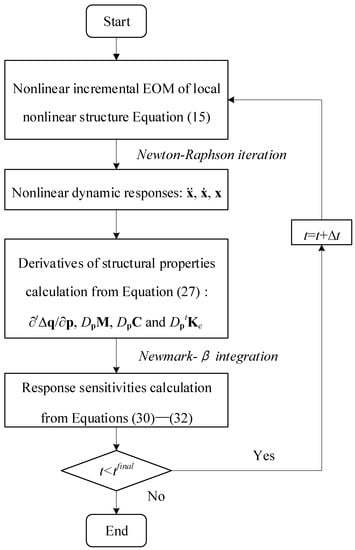
Figure 1.
Flow chart of transient response sensitivity analysis.
- (1)
- The nonlinear algebraic equations are solved using the Newton–Raphson iteration scheme, and the transient responses of the structure with local nonlinearity are solved by Newmark-β method in the time range (t1 tfinal);
- (2)
- The derivatives of structural properties are determined with respect to the local nonlinear parameters in Equation (27), ∂t∆q/∂p, DpM, DpC, and DptKe;
- (3)
- For a given initial condition, the initial displacement and velocity sensitivities are zero: 0S = 0Ṡ = 0. By differentiating Equation (7) with respect to parameters under the initial condition:
Substituting these initial responses and initial sensitivities into Equation (28), the initial acceleration sensitivity can be calculated from the following equation:
The pseudo-code for initial response sensitivity analysis is listed in Algorithm 1.
| Algorithm 1. Pseudo-code for initial transient response sensitivity analysis. | |
| Procedure Initial Sensitivity (0x, 0ẋ, 0ẍ, M, C, K, 0q, p) | |
Input: initial transient responses, stiffness matrix, damping matrix, stiffness matrix, external force, and design parameters
|
Using the Newmark-β method [34], the algebraic sensitivity equation could be integrated numerically in time domain:
where β and γ are the parameters controlling the accuracy and stability of the numerical integration algorithm. The special choice of the controlling parameters is β = 1/2 and γ = 1/4 (the unconditionally stable constant average acceleration method). Time step Δts denotes the constant time increment for sensitivity analysis, which can provide exact results with enough of a small step. Substituting Equations (30) and (31) into sensitivity Equation (26), the incremental sensitivity formulation is rewritten as:
Equations (30)–(32) give the general formulation to compute the transient response sensitivities. Comparing Equations (15) and (32), the key point in the DDM sensitivity analysis is that the same coefficient matrices with the response analysis are applied to sensitivity analysis. Once the dynamic response of the structure is obtained, the sensitivity equation, Equation (32), has the same left-hand-side matrix consistent with Equation (15) for the response analysis. Hence, only the equivalent excitation tQe needs to be recomputed. The computational procedure is more efficient to determine the transient response sensitivity in the interested time range compared to the finite-difference method. The pseudo-code for direct sensitivity analysis is listed in algorithm 2.
| Algorithm 2. Pseudo-code for nonlinear transient response sensitivity analysis using direct differential method. | |
| Procedure Transient Sensitivity (0S, 0Ṡ, 0, M, C, K, x, ẋ, ẍ, p) | |
Input: initial transient response sensitivities, mass matrix, damping matrix, stiffness matrix, transient responses, design parameters
|
3. Case Studies
Three case studies, a Duffing system, a nonlinear MDOF system, and a beam structure, are investigated in this section. The finite difference method (FDM) and asymptotical analysis method are applied to verify the performance, and the effects of parameter perturbation step size and secular term are discussed. The nonlinear MDOF and cantilever beam focus on the accuracy of the direct differentiation method for the application to an FE model, considering different integrating time steps.
3.1. Duffing Oscillator
An undamped Duffing oscillator with mass m = 1 kg, linear stiffness k = 1 N/m, and the cubic nonlinear stiffness knl = 0.01 N/m3 is applied to calculate the transient response sensitivities. The governing equation is:
3.1.1. Finite Difference Sensitivity Analysis
The finite difference method is the general approach to an application on computers for sensitivity calculation. The main idea of the FDM is to approximate the first-order derivative s by a parameter perturbation. The forward difference formula for the nonlinear stiffness knl is:
where ε is the truncation error, ε = Δknl/2|x″(knl + δknl)|, and (*)″ means the second-order sensitivity with respect to *. The accuracy of the sensitivity approximated by the forward difference is dependent on the parameter step size, ∆knl. As shown in Equation (34), the reduction in the parameter step size could minimize the truncation error ε. However, a too small parameter step size, in turn, enlarges the condition errors, which is caused by the round-off errors in (tx(knl + Δknl)-tx(knl))/∆knl. In Section 3.1.3, the effect of the parameter step size on the sensitivity accuracy will be discussed.
3.1.2. Asymptotical Sensitivity Analysis
Using the Poincaré method (PCM) and the Lindstedt–Poincaré method (LPM), with initial condition 0x = u0 and 0ẋ = 0, the asymptotically analytical solution of x could be obtained. The asymptotically analytical expression of the response sensitivity is given:
in which ω0 is the natural frequencies of the underlying linear system: ; (*)′ means the first derivative with respect to the local nonlinear parameters. In the Poincaré solution, Equation (35), the frequency is the same as the underlying linear structure and is independent to the nonlinear stiffness. The solution of the sensitivities calculated from the Poincaré method is concise compared with the Lindstedt–Poincaré solution. However, the accuracy for long time response calculated from Equation (35) will decrease because of the secular term tsinω0t. Moreover, the accuracy of these sensitivities will also decrease due to the existence of the secular term.
3.1.3. Results Comparison and Discussion
The influence of parameter perturbation and secular term were discussed as follows.
Case 1. Effect of the parameter perturbation step size
The initial displacement and velocity are 0x = u0 = 1 mm and 0ẋ = v0 = 0, respectively. The transient response, with a time range of 0 < t ≤ 10 s, can be numerically obtained from Equation (33). Based on the exact transient solution, the DDM-based response sensitivities could be calculated by solving the incremental sensitivity equation. The time step used in the time integration of both schemes (response and sensitivity analysis) is ∆t = 0.001 s. The two asymptotically analytical solutions (the PCM and the LPM) of displacement sensitivity could be calculated from Equations (35) and (36) directly. The sensitivities of the velocity and acceleration can also be determined analytically, respectively, taking the first and second derivative of Equations (35) and (36) with respect to time and, then, with respect to variables. Perturbing the sensitivity parameter knl, the FDM-based sensitivity will be computed. In this case, the parameter step size ∆knl is selected from 10−4 knl to 10−6 knl.
Figure 2 shows the response (displacement, velocity, and acceleration) sensitivities calculated by the DDM, the FDM, the PCM, and the LPM. The effect of parameter perturbation step size Δknl on the response sensitivity is studied with three different situations. In Figure 2, the DDM sensitivity matches well with the analytical sensitivities computed by the LPM and the PCM. The inaccuracy between the FDM sensitivity and analytical sensitivity is shown obviously in the case of small parameter perturbation step size (Δknl = 10−6 knl). The inaccuracy of the transient response sensitivity is caused by the condition error of the small parameter perturbation step size [24]. To further investigate the influence of the parameter perturbation step size, a large initial displacement is employed to the Duffing oscillator.
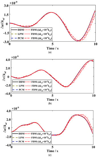
Figure 2.
Sensitivities of (a) displacement, (b) velocity, and (c) acceleration with respect to the nonlinear stiffness knl in different perturbations (0u = 1 mm).
Figure 3 illustrates the acceleration sensitivity with respect to the nonlinear stiffness using these four methods with the initial displacement 0u = 1 cm and the parameter perturbation step size Δknl = 10−6 knl. The nonlinear characteristic of this case is more obvious with an increase in the initial displacement, and the accuracy of the sensitivity calculated by the FDM has also been improved as compared with the results shown in Figure 2c. It is shown that the initial conditions of the nonlinear structural vibration affect the selection of parameter perturbation step size in the FDM method, and then affect the accuracy of the nonlinear transient response sensitivity analysis. This is because large initial conditions make the nonlinear behavior of the nonlinear structure more obvious.
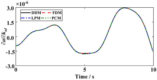
Figure 3.
Acceleration sensitivity with respect to the nonlinear stiffness knl (0u = 1 cm and ∆knl = 10−6 knl).
Case 2. Effect of the secular term
The secular term tsinω0t in the PCM precludes its potential application in long-time dynamic response analysis as the low accuracy of the long-time response, which has a negative effect on the transient response sensitivity computation. The initial condition is set to 0u = 0.2 m and 0v = 0, and the computing time ranges are 0 < t ≤ 20 s, 0 < t ≤ 200 s, and 0 < t ≤ 400 s for sensitivity analyses, respectively. In the analytical results, the amplitude of the PCM response will be increasing for the long-time calculation. The improved LPM avoids the passive effect of the secular term on the response, and the solution computed by Equation (36) is accurate. Thus, sensitivities calculated by the LPM will be used as the reference in comparing the results obtained by the DDM, the FDM, and the PCM. For the DDM- and the FDM-sensitivity analysis, the time step Δt and the parameter step size Δknl are 0.001 s and 10−3 knl, respectively.
Figure 4 illustrates the relationship of nonlinear transient response sensitivities, such as displacement, velocity, and acceleration, among the four methods with time ranges, (a)–(c) for 0 < t ≤ 20 s, (d)–(f) for 0 < t ≤ 200 s, and (h)–(i) for 0 < t ≤ 400 s, respectively. For the short-time case, these sensitivities calculated by the DDM, the FDM, and the PCM match well with the sensitivities obtained by the LPM. With the increasing of the calculation time, the effect of the secular term for the PCM-based sensitivity analysis is more obvious, in which the relationship to the LPM vs. PCM is no longer a straight line as shown in Figure 4d–i. It can be concluded that the long-term nonlinear response sensitivity calculated by the LPM method is susceptible to the secular term. In addition, the sensitivities obtained by the DDM and the FDM have high accuracy for the short-time and long-time nonlinear response sensitivity analysis, once the transient response is accurate.
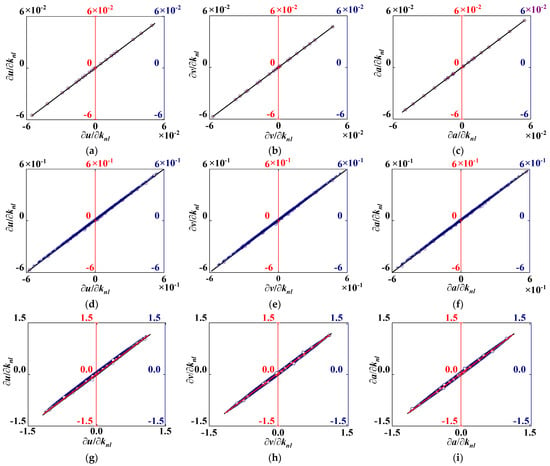
Figure 4.
Comparison of response sensitivities (a,d,g) displacement, (b,e,h) velocity, and (c,f,i) acceleration among the four methods (x: LPM, y: DDM, FDM, PCM) with different time intervals: LPM vs. DDM (black color), LPM vs. FDM (red color), LPM vs. PCM (blue color).
3.2. MDOF Nonlinear System
The accuracy of the DDM depends on the numerical integration schemes used to determine transient response and response sensitivity. Once the dynamic response is determined, the primary factor affecting the accuracy of the DDM sensitivity is the integrating time step Δts in the sensitivity equation, Equation (32). The computational accuracy generally increases with a decrease in the time step. The sensitivities calculated by the FDM are used as the reference in comparing the results obtained by the DDM with different time steps.
An MDOF system shown in Figure 5 is illustrated to investigate the computational accuracy of the DDM sensitivity. The properties of the MDOF are chosen as follows: the mass m1 = m2 = m3 = 5 kg, the linear stiffness k1 = k2 = k3 = k4 = 20 N/m, the damping coefficients c1 = c2 = 1 Ns/m, andthe cubic nonlinear stiffness knl1 = 5 N/m3 and knl2 = 2 N/m3. The initial displacement is u0 = [0.1 0 0]T and velocity v0 is zero. The calculating time interval is 0 ≤ t ≤ 50 s. The time step for dynamical response calculation is chosen as Δtd = 1.0 × 10⁻⁴ s, which can ensure the high accuracy of the dynamic response computation. The parameter perturbation step sizes for the FDM sensitivities calculation are chosen as Δknl1 = 10−3 knl1 and Δknl2 = 10−3 knl2.

Figure 5.
Simplified MDOF model with a cubic nonlinear spring.
The free response sensitivities of the third DOF with respect to the first nonlinear spring are shown in Figure 6. The results obtained from the DDM could match well with the referred FDM values at the long time interval. With the decrease in the time step in integration of sensitivity differential equation, the consistency is increasingly close to the referred values. To quantify the difference, the consistency of the sensitivity is verified by considering the relative error between the DDM and the FDM sensitivities. In this paper, the form of the relative error is:
where ||∗||2 means the second norm of vector ∗.
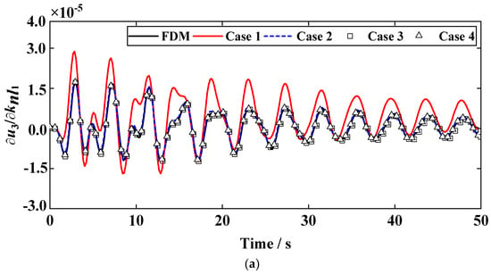
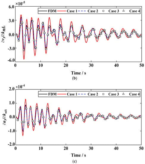
Figure 6.
Sensitivities of the 3rd DOF (a) displacement, (b) velocity, and (c) acceleration with respect to the knl1 at different time steps.
Table 1 shows the computational accuracy and efficiency of different time steps for the displacement, velocity, and acceleration sensitivities of third DOF with respect to nonlinear stiffness knl1. Figure 7 clearly shows the relationship among the time step, computational time, and relative error.

Table 1.
The results of different time steps in DDM for the computational efficiency and relative error in MDOF system (Δtd = 1.0 × 10⁻⁴ s).
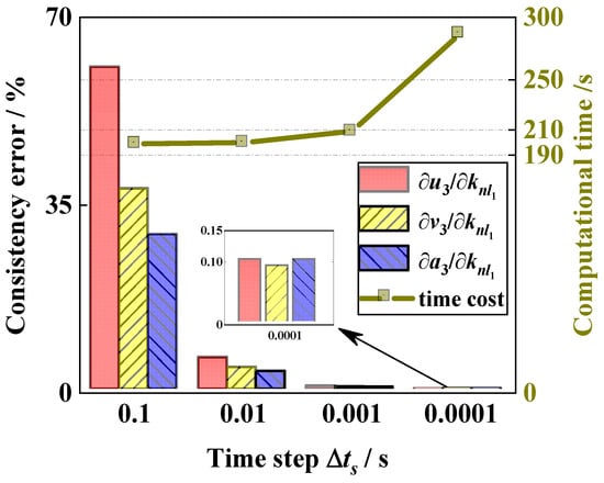
Figure 7.
The accuracy and computational time of the sensitivities obtained from the DDM versus the different time steps.
For the calculation of the free response sensitivity, the relative error for the DDM exists obviously when the time step is too large. At the time step Δts = 100Δtd, the maximum relative error of the response sensitivity is 5.96% (=∂u3/∂knl1) and the computational time is 199.97 s. When the time step becomes smaller, the relative errors are decreased but the computational time is increased extremely. A small relative error can be achieved using a large time step (Δts < 100Δtd) in the DDM transient response sensitivity analysis procedure.
3.3. Cantilever Beam with Nonlinear Springs
Figure 8 shows the model of a cantilever beam with nonlinear springs, where the local nonlinearities are set at the end point B. The cantilever beam is discretized into 10 Euler–Bernoulli beam elements. The length of the beam is l = 1 m and the section is the circle with radius r = 15 mm. The elastic modulus is E = 70 GPa, Poisson’s ratio is μ = 0.3, and density is ρ = 2.7 × 10³ kg/m3. The cubic nonlinear stiffness coefficients are knl1 = 10,000 N/m3 and knl2 = 200,000 N·m/rad3, respectively. The proportional damping matrix is C = a1M + a2K, and the scalar coefficients are a1 = a2 = 0.0001 in this example, respectively.
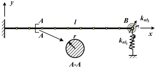
Figure 8.
Cantilever beam with locally nonlinear springs.
In order to compute the sensitivities of the nonlinear free vibration, the initial values are set to be: uB y = 0.01 m and θB z = 0.01 rad for initial displacements and zero for initial velocities. The dynamic responses are obtained by the Newmark-β numerical integration method; a time step Δtd that corresponds to Nt and steps per final time tf, for calculating, is Δtd = tf/Nt, e.g., tf = 0.005 s and Nt = 5 × 10³ in this case. The sensitivities of the responses (displacement, velocity, and acceleration) with respect to the nonlinear stiffness parameters are investigated. The analytical formulation of the sensitivities cannot be determined directly; the consistency of the DDM sensitivities is verified by comparing the FDM (0.1% parameter perturbation). The time step in the DDM algorithm for computing nonlinear response sensitivities in Equation (26) is Δts = Δtd. The comparison curve of response sensitivities using the DDM and the FDM with two parameters, knl1 and knl2, are shown in Figure 9. The relationship curve reflects the consistency between the DDM and the FDM. When the curve can be approximated by the relationship y = x, the consistency error of the two methods trends to zero.
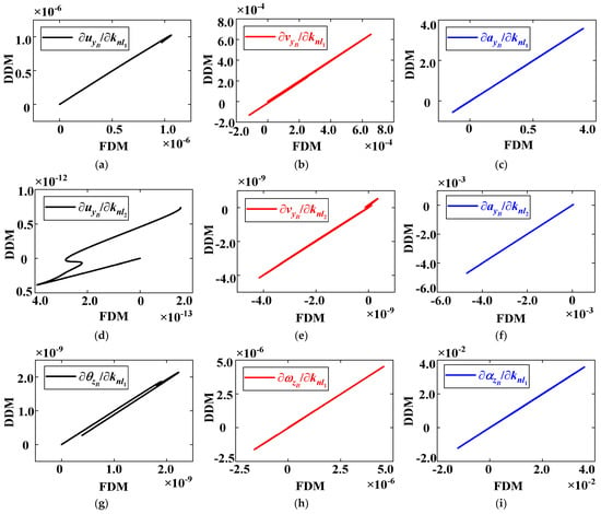

Figure 9.
Comparison curve of response sensitivities of point B (translation and rotation displacement, velocity, and acceleration) with respect to nonlinear stiffness parameters knl1 (a–c,g–i) and knl2 (d–f,j–l) with FDM and DDM at Nt = 5000.
Figure 9 illustrates the comparison curve of the response sensitivities (displacement, velocity, and acceleration response sensitivity) between the FDM and the DDM. Results show that the highest consistency exists in acceleration response sensitivities (see Figure 9c,f,i,l), for which the relationship curves almost satisfy the approximate function yDDM = xFDM. In contrast, the obvious non-consistencies on the displacement response sensitivities are shown in Figure 9a,d,g,j. The results show that the DDM can be applied to accurately compute the response sensitivity of a beam structure with local nonlinearities.
To illustrate that the consistency of the nonlinear response sensitivities of displacement and acceleration are different, the number of steps Nt is set to 5000, 10,000, 50,000, 100,000, and 200,000. The comparison of different Nt for sensitivity calculation is shown in Figure 10. It is concluded that the consistency error of the displacement sensitivity decreases significantly with the increasing of Nt. By contrast, the consistency error of acceleration sensitivity remains at the smallest level and generally converges as the Nt increases. The results show that the integration step in Newmark-β procedure has a great effect on the consistency for the displacement, velocity, and acceleration sensitivity solutions. Compared with the nonlinear MDOF system and cantilever beam, the consistency of the DDM sensitivities, especially for the displacement sensitivity, is affected by the integration time step size. Furthermore, the DDM method could also be effective for the sensitivity analysis of a complex nonlinear structure with large DOFs [39]. Particularly to compute the sensitivity of a nonlinear structure with higher dimensions, some nonlinear model order reduction method [41] needs to be combined with the DDM method for further investigation.
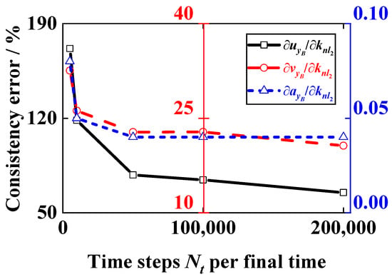
Figure 10.
Consistency error between DDM and FDM for response sensitivities at different steps Nt.
4. Conclusions and Discussion
In this paper, a direct differentiation method for nonlinear transient response sensitivity analysis for a Duffing oscillator, a nonlinear multiple-degrees-of-freedom system, and a cantilever beam with local nonlinearity was investigated. The method was verified by comparing with the finite difference method and asymptotical analysis method for different numerical examples. Furthermore, the effects on the accuracy and efficiency of the perturbation step, the secular term and the time step were conducted. The conclusions were drawn as follows:
- (1)
- The DDM-based transient response sensitivities match well with the analytical and numerical sensitivities computed by the PCM and FDM, respectively.
- (2)
- The accurate DDM transient response sensitivity can be obtained based on the accurate nonlinear transient response; the computational efficiency of the response sensitivity is improved using a suitable time step, especially for a long-time dynamic response sensitivity analysis.
- (3)
- The selection of the parameter perturbation step size in FDM sensitivity analysis is affected by the nonlinear behaviors caused by the initial conditions; a large perturbation step size can be selected to improve the accuracy of the transient response sensitivity for a weak nonlinear structure with small initial conditions.
The DDM sensitivity analysis method was demonstrated on three different examples and the accuracy was verified compared with the LPM, the PCM, and the FDM. However, the prerequisite of the DDM method is that the nonlinear function is continuously differentiable, which limits its application in sensitivity analysis of non-smooth nonlinear structures. An alternative scheme is to transform the non-smooth function by smoothing method to make it derivable, and then directly differentiate to obtain the corresponding sensitivity analysis equation. In addition, sensitivity analysis of a nonlinear structures is also affected by parameter uncertainty, and the global DDM method for nonlinear structure under consideration of parameter uncertainty is worthy of further study.
Author Contributions
Conceptualization, Z.C. and J.Y.; funding acquisition, Z.C.; methodology, Z.C. and Z.J.; resources, J.Y.; software, Z.J. and D.L.; validation, Z.C. and Z.J.; writing—original draft preparation, Z.C.; writing—review and editing, Z.C., J.Y., Z.J. and D.L. All authors have read and agreed to the published version of the manuscript.
Funding
This research was funded by the Natural Science Foundation of Chongqing (No. cstc2021jcyj-bshX0106).
Data Availability Statement
Not applicable.
Conflicts of Interest
The authors declare no conflict of interest.
Nomenclature
| M | Structural mass matrix |
| C | Structural damping matrix |
| K | Structural stiffness matrix |
| fnl, fnl (p,x,ẋ) | Nonlinear force vector |
| q(t) | External force vector |
| x, ẋ, ẍ | Structural displacement, velocity, and acceleration vector |
| p | Design parameter vector |
| fα | Nonlinear restoring force of the αth local nonlinear element |
| rα | Relative displacement vector of the αth local nonlinear element |
| tα | Transforming matrix of the αth local nonlinear element |
| tKnl | Nonlinear stiffness matrix at time t |
| tKe | Equivalent stiffness matrix at time t |
| , , | Defined displacement, velocity and acceleration sensitivity matrix |
| tQe | Equivalent excitation vector at time t |
| β, γ | Numerical integrating constants in Newmark-β method |
| knl | Nonlinear stiffness coefficient |
| cnl | Nonlinear damping coefficient |
| ω0 | Natural frequency of linear system |
| u0, v0 | Initial displacement and velocity |
| m, c, k | Linear mass, damping, and stiffness coefficient |
| E | Elastic modulus |
| ρ | Density |
| μ | Poisson’s ratio |
| a1, a2 | Coefficients of proportional damping |
| ⊗ | Kronecker tensor produce |
| Dp (*) | Partial differential of matrix (*) with respect to design parameter p |
References
- Qian, G.; Mahdi, A. Sensitivity Analysis Methods in the Biomedical Sciences. Math. Biosci. 2020, 323, 108306. [Google Scholar] [CrossRef] [PubMed]
- Khan, S.; Al-Shuhail, A.A.; Khulief, Y.A. Numerical Modeling of The Geomechanical Behavior of Ghawar Arab-D Carbonate Petroleum Reservoir Undergoing CO2 Injection. Environ. Earth Sci. 2016, 75, 1–15. [Google Scholar] [CrossRef]
- Rihan, F.A. Sensitivity Analysis for Dynamic Systems with Time-lags. J. Comput. Appl. Math. 2003, 151, 445–462. [Google Scholar] [CrossRef]
- Cao, L.; Liu, J.; Jiang, C.; Liu, G. Optimal Sparse Polynomial Chaos Expansion for Arbitrary Probability Distribution and Its Application on Global Sensitivity Analysis. Comput. Methods Appl. Mech. Eng. 2022, 399, 115368. [Google Scholar] [CrossRef]
- Takezawa, A.; Kitamura, M. Sensitivity Analysis and Optimization of Vibration Modes in Continuum Systems. J. Sound Vib. 2013, 332, 1553–1566. [Google Scholar] [CrossRef]
- Cao, Z.F.; Fei, Q.G.; Jiang, D.; Wu, S.Q. Substructure-based Model Updating using Residual Flexibility Mixed-Boundary Method. J. Mech. Sci. Technol. 2017, 31, 759–769. [Google Scholar] [CrossRef]
- Xu, Y.J.; Tian, Y.; Li, Q.Y.; Li, Y.B.; Zhang, D.H.; Jiang, D. Vibro-Impact Response Analysis of Collision with Clearance: A Tutorial. Machines 2022, 10, 814. [Google Scholar] [CrossRef]
- Sun, Y.H.; Li, M.X.; Dong, R.W.; Chen, W.Y.; Jiang, D. Vision-Based Detection of Bolt Loosening Using YOLOv5. Sensors 2022, 22, 5184. [Google Scholar] [CrossRef]
- Lu, Z.R.; Law, S.S. Features of Dynamic Response Sensitivity and Its Application in Damage Detection. J. Sound Vib. 2007, 303, 305–329. [Google Scholar] [CrossRef]
- Weng, S.; Tian, W.; Zhu, H.P.; Xia, Y.; Gao, F.; Zhang, Y.T.; Li, J.J. Dynamic Condensation Approach to Calculation of Structural Responses and Response Sensitivities. Mech. Syst. Signal Process. 2017, 88, 302–317. [Google Scholar] [CrossRef]
- Park, S.; Kapania, R.K.; Kim, S.J. Nonlinear Transient Response and Second-order Sensitivity using Time Finite Element Method. AIAA J. 1999, 37, 613–622. [Google Scholar] [CrossRef]
- Kim, N.H.; Choi, K.K. Design Sensitivity Analysis and Optimization of Nonlinear Transient Dynamics. Mech. Struct. Mach. 2001, 29, 351–371. [Google Scholar] [CrossRef]
- Cho, S.; Choi, K.K. Design Sensitivity Analysis and Optimization of Non-linear Transient Dynamics. Part I-Sizing Design. Int. J. Numer. Meth. Eng. 2000, 48, 351–373. [Google Scholar] [CrossRef]
- Liu, S.B.; Canfield, R.A. Continuum Shape Sensitivity for Nonlinear Transient Aeroelastic Gust Response. In Proceedings of the 52nd AIAA/ASME/ASCE/AHS/ASC Structures, Structural Dynamics and Materials Conference, Denver, CO, USA, 4–7 April 2011; p. 1971. [Google Scholar]
- Subramanian, A.; Mahadevan, S. Variance-based Sensitivity Analysis of Dynamic Systems with Both Input and Model Uncertainty. Mech. Syst. Signal. Process. 2022, 166, 108423. [Google Scholar] [CrossRef]
- Abbiati, G.; Marelli, S.; Tsokanas, N.; Sudret, B.; Stojadinović, B. A global Sensitivity Analysis Framework for Hybrid Simulation. Mech. Syst. Signal Process. 2021, 146, 106997. [Google Scholar] [CrossRef]
- Wan, H.-P.; Ren, W.-X.; Todd, M.D. Arbitrary Polynomial Chaos Expansion Method for Uncertainty Quantification and Global Sensitivity Analysis in Structural Dynamics. Mech. Syst. Signal Process. 2020, 142, 106732. [Google Scholar] [CrossRef]
- Bogomolni, M.; Kirsch, U.; Sheinman, I. Nonlinear Dynamic Sensitivities of Structures using Combined Approximations. AIAA J. 2006, 44, 2765–2772. [Google Scholar] [CrossRef]
- Haftka, R.T.; Adelman, H.M. Recent Developments in Structural Sensitivity Analysis. Struct. Optim. 1989, 1, 137–151. [Google Scholar] [CrossRef]
- Wang, B.P.; Apte, A.P. Complex Variable Method for Eigensolution Sensitivity Analysis. AIAA J. 2006, 44, 2958–2961. [Google Scholar] [CrossRef]
- Kim, S.H.; Ryu, J.Y.; Cho, M.Y. Numerically Generated Tangent Stiffness Matrices using the Complex Variable Derivative Method for Nonlinear Structural Analysis. Comput. Methods Appl. Mech. Eng. 2011, 200, 403–413. [Google Scholar] [CrossRef]
- Garza, J.; Millwater, H. Multicomplex Newmark-Beta Time Integration Method for Sensitivity Analysis in Structural Dynamics. AIAA J. 2015, 53, 1188–1198. [Google Scholar] [CrossRef]
- Cao, Z.F.; Fei, Q.G.; Jiang, D.; Kapania, R.K.; Wu, S.Q.; Jin, H. A Sensitivity-based Nonlinear Finite Element Model Updating Method for Nonlinear Engineering Structures. Appl. Math. Model. 2021, 100, 632–655. [Google Scholar] [CrossRef]
- Keulen, F.V.; Haftka, R.T.; Kim, N.H. Review of Options for Structural Design Sensitivity Analysis. Part 1: Linear Systems. Comput. Methods Appl. Mech. Eng. 2005, 194, 3213–3243. [Google Scholar] [CrossRef]
- Cho, M.; Kim, H. A Refined Semi-analytic Design Sensitivity Based on Mode Decomposition and Neumann Series. Int. J. Numer. Meth. Eng. 2005, 62, 19–49. [Google Scholar] [CrossRef]
- Wang, W.J.; Clausen, P.M.; Bletzinger, K.U. Improved Semi-analytical Sensitivity Analysis using A Secant Stiffness Matrix for Geometric Nonlinear Shape Optimization. Comput. Struct. 2015, 146, 143–151. [Google Scholar] [CrossRef]
- Fernandez, F.; Tortorelli, D.A. Semi-analytical Sensitivity Analysis for Nonlinear Transient Problems. Struct. Multidiscip. Optim. 2018, 58, 2387–2410. [Google Scholar] [CrossRef]
- Kang, B.S.; Park, G.J.; Arora, J.S. A Review of Optimization of Structures Subjected to Transient Loads. Struct. Multidiscip. Optim. 2006, 31, 81–95. [Google Scholar] [CrossRef]
- Yun, K.S.; Youn, S.K. Design Sensitivity Analysis for Transient Response of Non-viscously Damped Dynamic Systems. Struct. Multidiscip. Optim. 2017, 55, 2197–2210. [Google Scholar] [CrossRef]
- Zhu, Y.T.; Dopico, D.; Sandu, C.; Sandu, A. Dynamic Response Optimization of Complex Multibody Systems in A Penalty Formulation using Adjoint Sensitivity. J. Comput. Nonlinear Dyn. 2015, 10, 031009. [Google Scholar] [CrossRef]
- Lauss, T.; Oberpeilsteiner, S.; Steiner, W.; Nachbagauer, K. The Discrete Adjoint Gradient Computation for Optimization Problems in Multibody Dynamics. J. Comput. Nonlinear Dyn. 2017, 12, 031016. [Google Scholar] [CrossRef]
- Yan, K.; Cheng, G.D. An Adjoint Method of Sensitivity Analysis for Residual Vibrations of Structures Subject to Impacts. J. Sound Vib. 2018, 418, 15–35. [Google Scholar] [CrossRef]
- Kerschen, G.; Worden, K.; Vakakis, A.F.; Golinval, J.C. Past, Present and Future of Nonlinear System Identification in Structural Dynamics. Mech. Syst. Signal Process. 2006, 20, 505–592. [Google Scholar] [CrossRef]
- Conte, J.P.; Vijalapura, P.K.; Meghella, M. Consistent Finite-element Response Sensitivity Analysis. J. Eng. Mech. 2003, 129, 1380–1393. [Google Scholar] [CrossRef]
- Gu, Q.; Wang, G. Direct Differentiation Method for Response Sensitivity Analysis of a Bounding Surface Plasticity Soil Model. Soil. Dyn. Earthq. Eng. 2013, 49, 135–145. [Google Scholar] [CrossRef]
- Li, Y.; Huang, S.R.; Lin, C.; Gu, Q.; Qiu, Z.J. Response Sensitivity Analysis for Plastic Plane Problems Based on Direct Differentiation Method. Comput. Struct. 2017, 182, 392–403. [Google Scholar] [CrossRef]
- Ding, Z.; Li, L.; Zou, G.M.; Kong, J.Y. Design Sensitivity Analysis for Transient Response of Non-viscously Damped Systems Based on Direct Differentiate Method. Mech. Syst. Signal Process. 2019, 121, 322–342. [Google Scholar] [CrossRef]
- Wojtkiewicz, S.F.; Johnson, E.A. Efficient Sensitivity Analysis of Structures with Local Modifications. I: Time Domain Responses. J. Eng. Mech. 2014, 140, 04014067. [Google Scholar] [CrossRef]
- Cao, Z.F.; Fei, Q.G.; Jiang, D.; Zhang, D.H.; Jin, H.; Zhu, R. Dynamic Sensitivity-based Finite Element Model Updating for Nonlinear Structures using Time-Domain Responses. Int. J. Mech. Sci. 2020, 184, 105788. [Google Scholar] [CrossRef]
- Wang, X.; Hill, T.L.; Neild, S.A.; Shaw, A.D.; Haddad, K.H.; Friswell, M.I. Model Updating Strategy for Structures with Localised Nonlinearities using Frequency Response Measurements. Mech. Syst. Signal Process. 2018, 100, 940–961. [Google Scholar] [CrossRef]
- Touzé, C.; Vizzaccaro, A.; Thomas, O. Model Order Reduction Methods for Geometrically Nonlinear Structures: A Review of Nonlinear Techniques. Nonlinear Dyn. 2021, 105, 1141–1190. [Google Scholar] [CrossRef]
Publisher’s Note: MDPI stays neutral with regard to jurisdictional claims in published maps and institutional affiliations. |
© 2022 by the authors. Licensee MDPI, Basel, Switzerland. This article is an open access article distributed under the terms and conditions of the Creative Commons Attribution (CC BY) license (https://creativecommons.org/licenses/by/4.0/).