Abstract
Hovering ability is the basis of fixed-point monitoring and tracking of an aircraft. Herein, we propose a new hovering vehicle inspired by bird feathers, with an airfoil composed of passive opening and closing feather units. Two wings of the prototype are vertically distributed and driven in anti-phase linear reciprocation. The lift is generated by the asymmetric flow of air caused by the opening and closing of the feather unit. The design of the vehicle is simple and can be incorporated into a large-area hovering platform for large loads. In this paper, the design and fabrication of the vehicle are described, along with an aerodynamic theoretical model of the vehicle kinematics. The correctness of the model was verified by numerical calculations and tests on the opening and closing characteristics of the plume unit. The opening and closing characteristics of the feather unit were investigated and revealed through controlled-variable experiments. An experimental prototype with a mass of 52 g was built. During preliminary flight tests, the vibration frequency was controlled to verify that the prototype was capable of hovering and vertical takeoff and landing.
1. Introduction
Hoverable unmanned aerial vehicles have attracted research attention because of their important role in defense and civil applications. In particular, significant effort is devoted to the design and fabrication of new vehicles with lifting, hovering, and propulsion functions, incorporating bionic principles that mimic natural organisms using unstable aerodynamic mechanisms [1,2] in the low-Reynolds-number range [3].
Scientists have used birds [4] or insects as sources of inspiration for studying and designing flying machines. Flapping-wing flight modes in nature are roughly classified into two types based on the type of wing movement [5]. The first is the flight mode represented by pigeons and hawks, which cannot takeoff vertically or hover [6,7]. They glide up and down by fluttering their wings, generate lift in the downstroke, and use a small angle of attack of the wings and special wing shape and motion for takeoff and landing. The second type of flight is represented by fruit flies [8] and hummingbirds [9] that hover in a near-horizontal plane by flapping their wings and rapidly flipping them [10] on each stroke to generate lift throughout the cycle. Most existing hovering flutter planes have been designed and built using this model. By simulating the shape and flight principles of a fly, Steltz et al. and Jafferis et al. designed the microlight vehicle MFI [11] and RoboBee [12], respectively. Both of these use a piezoelectrically driven linkage mechanism to perform wing flapping motions and achieve hovering and vertical takeoff and landing, but are unable to achieve precisely controlled flight. By simulating the shape and flight principle of a hummingbird, AeroVironment designed a flapping-wing micro air vehicle (FMAV) that uses a rope-driven mechanism to achieve a large flutter angle and a frequency of 30 Hz. The wing angle of attack was adjusted using a new twisting mechanism. The aircraft can achieve 11 min of stable hovering and controlled flight [9]. The robotic hummingbird of the University of Maryland, which is actuated by a single-crank dual-rocker mechanism and a guide rod mechanism, achieves four degrees of freedom of motion and generates much higher aerodynamic forces than a flutter-wing aircraft of the same size [13]. In addition, some FMAVs, such as the KU Beetle-mimicking flutter wings [14], the NUS-TL-Flapping wing micro air vehicle (MAV) [15,16], the oscillating-wing MAV [17], and the DelFly tailless aerial robotic flutter wing [18,19], mimic the flight patterns of insects or hummingbirds to achieve controlled hovering flight.
Although there have been many achievements in research on hoverable flutter-wing vehicles, owing to the complexity of biological motion and the limitations of existing manufacturing processes and materials, existing vehicles still face many challenges in achieving the high lift characteristics exhibited by organisms. Many new hoverable vehicles are also being developed to explore more efficient flight. The jellyfish-like hovercraft [20,21] of New York University was designed and built by imitating the motion of a jellyfish using a motor-driven linkage mechanism, thus, simplifying the mechanism design and flight control requirements. The flutter rotor [22] developed by Cranfield University and Beijing University of Aeronautics and Astronautics combines insect flutter motion and rotor motion to provide a higher lift advantage through flutter and passive rotor motion. The flutter design of these vehicles is driven by the rotation of a simple integral wing from the root. A gyroscopic flying robot [23,24] can hover along vertical rails by changing the variable wing angle of orientation depending on the rotation angle. However, the heavy and complex organization is a drawback. The semi-biological pigeon robot [25,26] designed by Stanford University combines a flying robot and real feathers, which attempt to precisely mimic the shape of a bird’s altered wings to maintain and manipulate flight. Although the robot cannot achieve hovering flight, it provides good insight for creating variable-winged vehicles.
In this study, a three-dimensional physical model of a new variable wing hovering vehicle was developed (Figure 1). The main purpose of this study was to provide theoretical guidance for the development of a large-load hovering vehicle with a simple actuation mode and large-area array airfoil. The microstructure of bird feathers and the change in their structures during flight [27,28] inspired the design of a variable-array feather airfoil. The airfoil design is composed of spiracle units that can be opened and closed passively. The two wings are distributed vertically and vibrate reciprocally in opposite phases. This design ensures consistent speed throughout the airfoil, and the relative motion of the two airfoils facilitates the offset of the airfoil inertial forces to improve the vehicle stability. To facilitate the design of the vehicle, a theoretical aerodynamic model of vehicle kinematics was developed and validated by numerical calculations and tests of the spiracle unit’s opening and closing characteristics. The opening and closing characteristics of the spiracle unit were investigated through controlled-variable experiments, whose results provided guidance for the parameter design of the prototype.
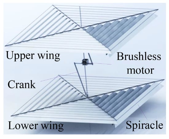
Figure 1.
Three-dimensional MAV model.
2. Micro-Aerial Vehicle Design and Kinematics
2.1. Bird Feather-like Array of Spiracle Wings Design
Pigeons are highly skilled in flight. Figure 2a–c shows the structure of the primary flight feathers of pigeons. The feathers are epidermal derivatives unique to birds that assume the function of flying, and the large feathers located in the wings, the flight feathers, are the feathers that power the bird’s flight. Each flight feather consists of a feather shaft and soar on either side, as shown in Figure 2a. Figure 2b shows that the soar is composed of a series of branches arranged in parallel and at a certain angle with the feather shaft. The feather branches are composed of the shaft and willow leaf-shaped hooked and unhooked branchlets on both sides, and the two types of branchlets are arranged in a tile-like pattern with the small hooks hooked to each other to form a tight feather tail, as shown in Figure 2c. The opening (Figure 2d) and closing (Figure 2e) of the feathers during flight causes bilateral airflow through asymmetry. When the wings are fluttering upward, the feather twigs are separated by airflow to reduce drag. When fluttering downward, the feather twigs cover each other by inertial force, airflow, and small hooks to increase lift.
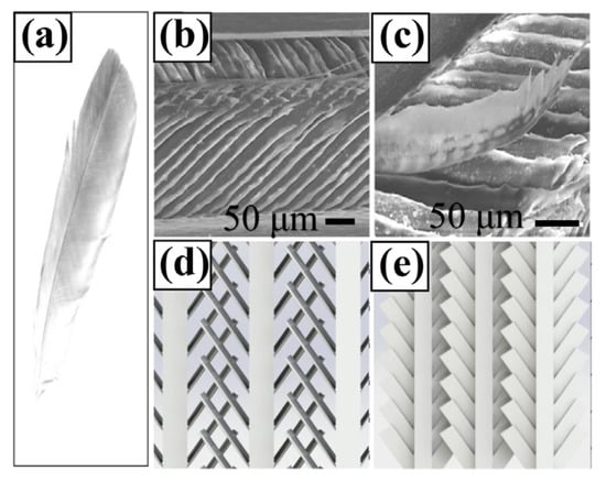
Figure 2.
Stacked microstructure (a–c) and physical model (d,e) of pigeon feathers.
The airfoil design in this study, with an array of spiracles, was inspired by the flying feather microstructure. The spiracle unit consists of a frame and film, as shown in Figure 3a. One side of the film is fixed to the frame and the other three sides are free. Figure 3b shows the change in the attitude of the spiracle during one cycle of motion. The film closes the spiracle under the action of airflow resistance, inertial force, and frame shielding during downward vibration, and opens the spiracle under the action of airflow resistance and inertial force during upward vibration. When the spiracle unit is closing and flapping down to the lowest point, the lifting force decreases, owing to the reduction in the moving speed. The membrane starts to separate from the frame under the action of gravity, the lifting force, and the inertial force before moving to the lowest point. As a result, the spiracle unit is open at the lowest point. The opening and closing of the spiracle during one cycle cause asymmetric airflow and generate lift.
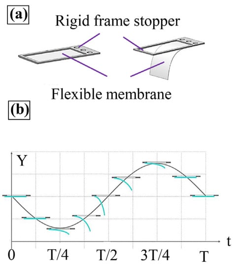
Figure 3.
Passive spiracle design: (a) Physical model of the spiracle unit. (b) Model of the opening and closing of the spiracle unit in one vibration cycle.
2.2. Wing Design
Making a lightweight and strong airfoil is key to achieving hovering flight. Figure 4 shows the design details of the array-spiracle airfoil. Unlike most airfoils, which are made of rods and films, the array airfoil is made of rods, thin wires, and films, which significantly reduces the airfoil mass, while maintaining stiffness. The overall size of the airfoil was 30 × 30 cm, with a mass of 12 g. Four carbon fiber rods were cross-fixed to the central slider. The length, width, and height of the carbon fiber rods were 20 cm, 1.5 mm, and 2.0 mm, respectively. Holes with a diameter of 1 mm were drilled on the side of the rods at 3-cm intervals to facilitate the stringing of polyurethane rubber elastic threads, 0.5 mm in diameter, to form a mesh structure. The polyethylene film was attached to the wire near the center end, and the other end was below the adjacent wire and kept free. The width of the film was 2.5 cm and slightly larger than the spacing between the two wires. The filaments require a certain tension but cannot cause the airfoil to bend, and a carbon fiber rod, 1 mm in diameter and 2.5 cm in length was fixed in the middle of the filaments to enhance the stiffness of the film plume. These designs ensure that the spiracle stack is closed during the downward vibration of the airfoil and open during the upward vibration of the spiracle rotation, thus, generating lift.
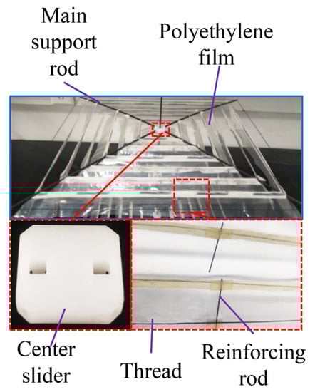
Figure 4.
Array-spiracle wing design.
2.3. Wing Motion Design
The vehicle design incorporates a layout of double-layered feathers arranged up and down, with both wing surfaces fluttering in reverse at the same speed during flight. Figure 5 shows that the opening and closing of the spiracle unit makes the lift of the lower vibrating airfoil always greater than the drag of the upper array in one cycle; therefore, the entire process generates additional lift to balance gravity and achieve the ascent and hovering of the vehicle. At the same time, the double-layer arrangement of the design promotes the mutual offset of inertial forces during airfoil vibration, which enhances vehicle stability. This driving mode is simple and ensures uniform velocity distribution over the whole wing surface. This is conducive to large loads generated by super-large wing surface drive.
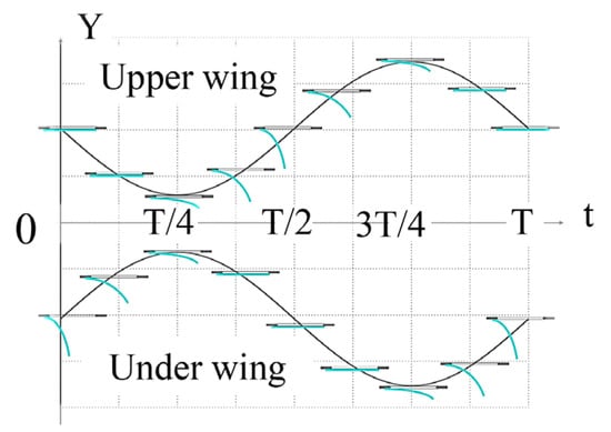
Figure 5.
Opening and closing state of biplane spiracles in one cycle.
A motor and linkage mechanism were used for the airfoil drive design, as shown in Figure 6. A brushless motor (2200 KV, 11.2 V) and micro-reducer (1:20, 12.6 g) were placed in the middle of the upper and lower airfoils. The center crank was made of hard steel wire, 1.4 mm in diameter, bent with a 30 mm turning radius, and the center crank and center slider of the upper and lower airfoils were connected by a carbon fiber linkage and spring. The springs were used as damping and energy storage/release elements to reduce mechanical shock and energy loss during changes in the airfoil vibration direction.
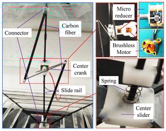
Figure 6.
Drive system design.
3. Kinematic and Aerodynamic Model of the Spiracle Unit
Quasi-definite aerodynamic theory and propeller unit theory were used to calculate the lift force for one cycle. Figure 7 shows the side view of the biplane vehicle and the plenum unit. The inertial coordinate system is denoted by [X, Y, Z]T , the coordinate system of the fixed vehicle is denoted by [x, y, z]T, and the corresponding unit vector [i,j,k] is attached to the center-of-mass position. Any spiracle unit on the left side of the upper airfoil can be used to build the computational model, which can also be extended to the spiracle units on the right and lower airfoils. The unit vector of the spiracle film is denoted by [m,n,p]. The motion cycle of the spiracle unit was divided into lower and upper vibrational openings. The velocity of the spiracle frame v0 (t) is expressed as:
where L0 is the crank radius, L1 is the linkage length, L2 is the displacement of the upper airfoil, and θ is the angle between the crank and vertical direction.
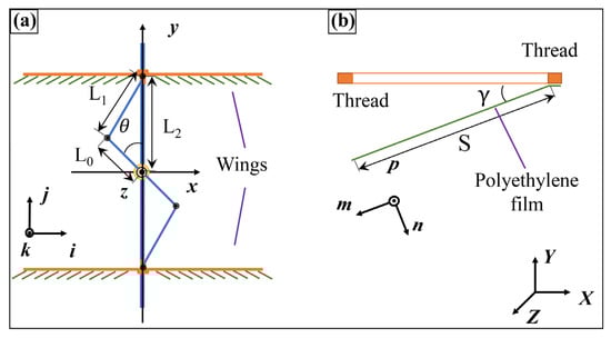
Figure 7.
Side view of the flight (a) and spiracle unit (b).
In the process of vibration, the film produces a bending motion because of gravity, inertial force, and wind resistance. For the calculation, it was assumed that the film was rigid and produced bending deformation at the bonded end with the frame; the motion and force analysis is shown in Figure 8. In the power stroke, the relationship between the unit vector [m,n,p] and fixed coordinate system of the vehicle is:
where γ is the angle of film bending with respect to the frame.
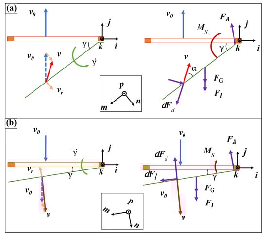
Figure 8.
Velocity (left) and force analysis (right) of the spiracle unit during wing-up flutter (a) and underwing flutter (b).
From blade element theory [29], the wind resistance for each defined cell d at time t is calculated as:
where is the film differential unit absolute velocity, is the drag component in the velocity direction, is the drag component in the velocity perpendicular direction, ρ is the air density, C is the width of the film, and and are the unit vectors in the velocity and velocity perpendicular directions, respectively. is the angle between the actual wind speed and the film, and are the drag coefficients in the corresponding directions, and is the film, which can be determined using the empirical formula [30]:
The angle of attack α(s,t) of each differential unit can be obtained by:
The film differential cell absolute velocity is the vector sum of the frame and film rotational linear velocity:
where is the defined linear velocity of the rotation of the differential unit with respect to the frame.
According to the rigid assumption on the film, the gravitational force acting at the center of gravity for a film of mass m is:
The inertial force on the film is:
In analyzing the force and motion of the film with the frame as the relative coordinate system, the total moment generated by the wind resistance, gravity, and inertial forces is:
The structural reverse moment at the film-frame connection is:
where the constant Ks is measured experimentally and is related to the type and thickness of the material.
The law of angular variation of the film relative to the frame can be obtained by:
where J is the rotational inertia of the film.
The angular velocity of the film and the angular variation can be obtained by integrating:
where and are determined by the initial state of the film, and γ ∈ [0,π/2].
In this example, the highest frame position is taken as the starting point, which is constrained by the frame at which time are equal to 0.
The forces and motion of the film were analyzed in the absolute inertial coordinate system. Analysis of the force and motion of the film in absolute inertial coordinate system:
The vertical component of is the force exerted by the film on the system (lift force).
4. Experimental Results
4.1. Construction of the Test System
The coordinated opening and closing of the spiracle unit during airfoil vibration is critical to the efficiency of lift generation; therefore, the spiracle unit attitude must be observed. Figure 9 shows the spiracle unit test system and observation equipment required for the experiment. The opening and closing characteristics of the spiracle units, observed using Olympus high-speed photographic equipment, were determined by a vibration system and the different sizes of the spiracle units. The vibration system used a stepper motor for the vibration drive and speed adjustment in the range of 0–20 Hz. The amplitude adjustment was achieved by changing the length of the connecting rod. The adjustment amplitudes were 20, 30, and 40 mm. The spiracle unit consisted of a resin frame and polyethylene film of 12.5 μm thickness, with five sizes: 10 × 10 mm, 10 × 15 mm, 10 × 20 mm, 10 × 25 mm, and 10 × 30 mm.
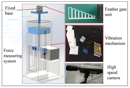
Figure 9.
Test system construction.
4.2. Numerical Calculation and Verification of the Aerodynamic Theoretical Model
MATLAB software was used to calculate the theoretical model and verify the correctness of the model through experiments. For verification purposes, the time of a cycle was divided into 1000 steps. Starting from the first step, the obtained motion and force state were carried to the second step, in which the state of all moments in a cycle, and change in the opening and closing state of the spiracle with time, were calculated. The active motion of the airfoil frame was a known quantity, and the motion of the frame forced the film to move. Once the film started to move, it generated changing inertial forces and wind resistance. The combination of these two forces and gravity caused the film to bend or stretch, which affected the motion of each element, and this, in turn, affected the forces on the vehicle. The relevant parameters are listed in Table 1. In addition, the bending characteristics of the film were obtained experimentally and used in the calculations. Initially, the film bent under the action of gravity. Figure 10a shows the bending state of the film under the action of gravity for different lengths. The relationship between the bending angle and the bending moment of the film was obtained by measuring its angle, as shown in Figure 10b. The curves were obtained by fitting the data:
where x is the bending moment value and is the angle value.

Table 1.
Parameter settings in numerical simulation.
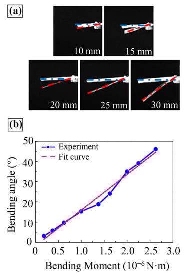
Figure 10.
Bending characteristics of spiracle film under gravity: (a) Bending state under gravity for films of length 10, 15, 20, 25, and 30 mm. (b) Film bending angle variation curve with bending moment.
Figure 11 shows the variation of the opening and closing angles of the plenum film with time during one cycle obtained by numerical calculation. The spiracle started to open after 3/8 cycle, reached the maximum angle by 3/4 cycle, and closed rapidly by the end of the cycle. The spiracle was closed during most of the downward movement of the frame and was open during the upward movement of the frame.
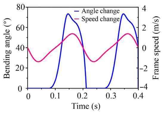
Figure 11.
Spiracle film angle change and frame vibration velocity change curve with time.
To verify the correctness of the calculated results, the change of the opening and closing angles of the spiracle film in vibration with the same parameters was captured by a high-speed camera, as shown in Figure 12a. The experimental spiracle started to open at time point 0.3 T, reaching the maximum opening angle at time point 0.6 T. The spiracle was completely closed at the end of one cycle. As shown in Figure 12b, the experimental results were compared with the calculated results. It was found that the experimental and theoretical curves closely matched at each important turning time point and the maximum spiracle opening angle was approximately the same. However, the spiracle opening speed in the experiment was faster than the theoretical opening speed, and it reached the maximum angle point before the theoretical time point. The reason might be that the junction between the frame and the film cannot be tightly attached under actual conditions, resulting in an angle of rotation that reduced the reverse torque applied to the film at the junction, thus, making the film easier to open. According to the overall trend, the theoretical and experimental results were consistent, which verified the accuracy of the theoretical and simulation calculations.
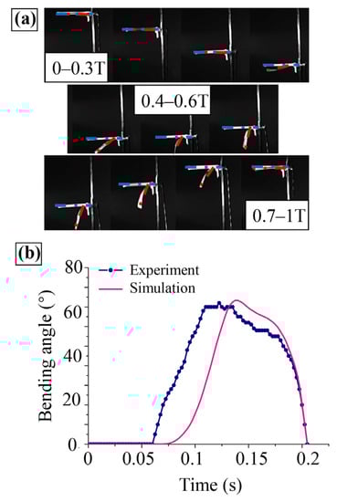
Figure 12.
Angle variation of spiracle unit during one vibration cycle. (a) Vibration observation of spiracle unit (time interval is 0.1 T). (b) Experimental and calculated values of angle variation.
4.3. Experimental Analysis of Spiracle Opening and Closing Characteristics
The changes in the spiracle film length, vibration amplitude, and vibration frequency have a great influence on the spiracle opening and closing characteristics. Therefore, the effects of the spiracle opening and closing characteristics were analyzed individually using the control variable method. Figure 13a shows the bending variation of the film in one cycle at different frequencies for a spiracle film length of 30 mm and an amplitude of 40 mm. The variable frequency did not affect the overall opening time of the spiracle, and as the frequency increased, the latter reached the maximum angle; however, its maximum angle also improved the opening and closing performance of the spiracle. When the frequency reached 12 Hz, the spiracle angle was able to open up to 90° and remained at this value for a long time, with excellent opening and closing performance. Figure 13b shows the change in the opening and closing of the plenum film in one cycle with different amplitudes at a vibration frequency of 12 Hz for a plenum film length of 30 mm. Increasing the amplitude increased the spiracle opening speed and angle maximum to a certain extent, and the spiracle maintained the maximum angle for a longer time with an amplitude of 40 mm. Figure 13c shows the opening and closing variations of the plenum film in one cycle for different plenum film lengths with a plenum amplitude of 40 mm and a vibration frequency of 12 Hz. The spiracle opening time point and total opening time were different but similar for different lengths. The opening angle increased with increasing spiracle length, and the increase was followed by a decrease under this parameter condition. The spiracle length of 30 mm exhibited the best opening and closing performance.
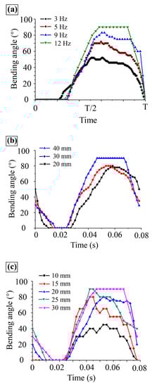
Figure 13.
Variation curve of spiracle angle with time in one cycle under different frequency (a), amplitude (b), and length values (c).
4.4. Prototype Manufacturing and Flight Experiments
Figure 14 shows the completed prototype. The total mass of the prototype was 52 g (excluding the battery and controller), and the stroke from the highest to the lowest position of the wing was 60 mm. The shortest distance between the two airfoils was 150 mm. Since the inertial forces generated by the symmetric inverse vibration of the two wings cancelled each other out, lift could be directly obtained by fixing the bottom of the prototype to the LH-Z05A (range 1000 g, accuracy 0.05% F.S) piezoresistance mechanical sensor (Shanghai Liheng Company, Shanghai, China). Figure 15 shows the average lift force of the prototype measured in five cycles at different vibration frequencies, which increased as the vibration frequency increased. When the vibration frequency was 11.3 Hz, the lift force exceeded the dead weight of the prototype, allowing hovering flight to be realized, theoretically.
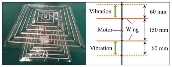
Figure 14.
Prototype of the MAV.
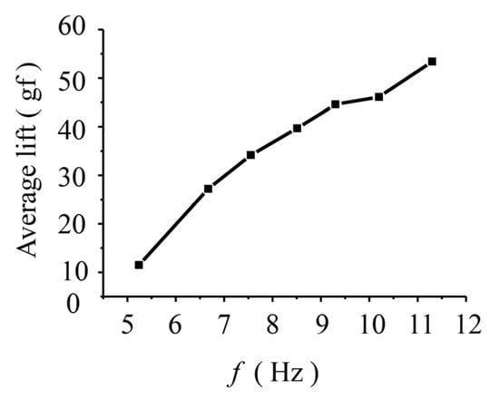
Figure 15.
Average lift of the MAV.
To visualize the flight capability of the prototype, a flight test was conducted under the guidance of a wire vertically threaded into the central rod. Figure 16 shows the vertical takeoff and hovering capability of the prototype by slowly increasing the vibration frequency to achieve vertical takeoff under the wire restraint. The vehicle generated enough lift to leave the support seat and rise 0.4 m in 2 s. The vertical takeoff and hovering abilities of the prototype were visually verified. However, the spiracles were distorted during movement, which caused uneven force distribution and prototype shaking. In future work, it is necessary to improve the selection of the spiracle materials, the wing–skeleton stiffness, and manufacturing process of the array-spiracle wing to solve this problem.
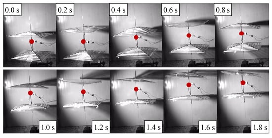
Figure 16.
MAV liftoff.
5. Conclusions
We proposed a flying machine scheme, inspired by the motion of bird feathers, that can achieve hovering and vertical takeoff and landing. Unlike existing biplanes or quadruple-flutter aircraft that mimic birds and insects, the prototype uses a simple motor linkage mechanism that vibrates up and down reciprocally to drive an airfoil composed of an array of feather units. The prototype successfully achieved hovering and vertical takeoff and landing under wire guidance. This work represents a successful attempt at designing and testing an array-type hoverable vehicle, which, in future research, could be developed with multiple driving units and two super-large airfoils with large load capacity and air operation capability. A kinematic and aerodynamic model of the plume unit was established, and the model was verified through MATLAB simulation and experimental tests. The effects of the plume film length, vibration amplitude, and vibration frequency on the passive opening and closing of the plume unit were investigated using the control variables method, and the structural and kinematic parameters, with good opening and closing characteristics, were determined, which will be useful in the next step of large-area array airfoil design. In this study, the lift efficiency of the prototype was not quantified. Furthermore, the prototype was not equipped with a power supply and on-board control system integration, which requires further research and design.
Author Contributions
Funding acquisition and conceptualization, D.Z.; revision, Y.L.; analysis and writing original draft, X.Z.; physical assembly, experimental verification, X.Z. and X.S; analysis of experimental results, X.Z., X.S., D.Z. and Y.L. All authors have read and agreed to the published version of the manuscript.
Funding
This research received no external funding.
Data Availability Statement
Not applicable.
Conflicts of Interest
The authors declare no conflict of interest.
References
- Lehmann, F.-O.; Pick, S. The aerodynamic benefit of wing–wing interaction depends on stroke trajectory in flapping insect wings. J. Exp. Biol. 2007, 210, 1362–1377. [Google Scholar] [CrossRef] [PubMed]
- Sane, S.P. Steady or Unsteady? Uncovering the Aerodynamic Mechanisms of Insect Flight. J. Exp. Biol. 2011, 214, 349–351. [Google Scholar] [CrossRef] [PubMed][Green Version]
- Ellington, C.P. The novel aerodynamics of insect flight: Applications to micro-air vehicles. J. Exp. Biol. 1999, 202, 3439–3448. [Google Scholar] [CrossRef] [PubMed]
- Zhu, Y.; He, X.; Zhang, P.; Guo, G.; Zhang, X. Perching and Grasping Mechanism Inspired by a Bird’s Claw. Machines 2022, 10, 656. [Google Scholar] [CrossRef]
- Deng, H.; Xiao, S.; Huang, B.; Yang, L.; Xiang, X.; Ding, X. Design optimization and experimental study of a novel mechanism for a hover-able bionic flapping-wing micro air vehicle. Bioinspir. Biomim. 2020, 16, 026005. [Google Scholar] [CrossRef]
- Platzer, M.F.; Jones, K.D.; Young, J.; Lai, J.C.S. Flapping Wing Aerodynamics: Progress and Challenges. AIAA J. 2008, 46, 2136–2149. [Google Scholar] [CrossRef]
- Mackenzie, D. A Flapping of Wings. Science 2012, 335, 1430–1433. [Google Scholar] [CrossRef] [PubMed]
- Nguyen, Q.V.; Truong, Q.T.; Park, H.C.; Goo, N.S.; Byun, D. Measurement of Force Produced by an Insect-Mimicking Flapping-Wing System. J. Bionic Eng. 2010, 7, S94–S102. [Google Scholar] [CrossRef]
- Keennon, M.; Klingebiel, K.; Won, H. Development of the Nano Hummingbird: A Tailless Flapping Wing Micro Air Vehicle. In Proceedings of the 50th AIAA Aerospace Sciences Meeting including the New Horizons Forum and Aerospace Exposition, Nashville, Tennessee, 9–12 January 2012; American Institute of Aeronautics and Astronautics: Reston, VA, USA, 2012. [Google Scholar]
- Shyy, W.; Aono, H.; Kang, C.K.; Liu, H. An Introduction to Flapping Wing Aerodynamics: Rigid Fixed-Wing Aerodynamics; Cambridge University Press: Cambridge, UK, 2013; pp. 42–89. [Google Scholar]
- Steltz, E.; Avadhanula, S.; Fearing, R.S. High lift force with 275 Hz wing beat in MFI. In Proceedings of the 2007 IEEE/RSJ International Conference on Intelligent Robots and Systems, San Diego, CA, USA, 29 October–2 November 2007; pp. 3987–3992. [Google Scholar]
- Jafferis, N.T.; Helbling, E.F.; Karpelson, M.; Wood, R.J. Untethered flight of an insect-sized flapping-wing microscale aerial vehicle. Nature 2019, 570, 491–495. [Google Scholar] [CrossRef]
- Coleman, D.A.; Benedict, M.; Amp, T.A.; Hrishikeshavan, V.; Chopra, I. Design, Development and Flight-Testing of a Robotic Hummingbird; Vertical Flight Society: Fairfax, VA, USA, 2015. [Google Scholar]
- Nguyen, Q.V.; Park, H.C.; Goo, N.S.; Byun, D. Characteristics of a Beetle’s Free Flight and a Flapping-Wing System that Mimics Beetle Flight. J. Bionic Eng. 2010, 7, 77–86. [Google Scholar] [CrossRef]
- Quoc-Viet, N.; Woei Leong, C.; Marco, D. An Insect-Inspired Flapping Wing Micro Air Vehicle with Double Wing Clap-Fling Effects and Capability of Sustained Hovering; Proc. SPIE: Bellingham, WA USA, 2015; p. 94290U. [Google Scholar]
- Nguyen, Q.-V.; Chan, W.L.; Debiasi, M. Hybrid Design and Performance Tests of a Hovering Insect-inspired Flapping-wing Micro Aerial Vehicle. J. Bionic Eng. 2016, 13, 235–248. [Google Scholar] [CrossRef]
- Zhou, X.; Zhang, D.; Huang, Z.; Song, X.; Liu, H.; Feng, L. Liftoff of a New Hovering Oscillating-wing Micro Aerial Vehicle. J. Bionic Eng. 2021, 18, 649–661. [Google Scholar] [CrossRef]
- de Croon, G.C.H.E.; Groen, M.A.; De Wagter, C.; Remes, B.; Ruijsink, R.; van Oudheusden, B.W. Design, aerodynamics and autonomy of the DelFly. Bioinspir. Biomim. 2012, 7, 025003. [Google Scholar] [CrossRef] [PubMed]
- Karásek, M.; Muijres, F.T.; De Wagter, C.; Remes, B.D.W.; de Croon, G.C.H.E. A tailless aerial robotic flapper reveals that flies use torque coupling in rapid banked turns. Science 2018, 361, 1089–1094. [Google Scholar] [CrossRef] [PubMed]
- Ristroph, L.; Childress, S. Stable hovering of a jellyfish-like flying machine. J. R. Soc. Interface 2014, 11, 20130992. [Google Scholar] [CrossRef]
- Fang, F.; Ho, K.L.; Ristroph, L.; Shelley, M.J. A computational model of the flight dynamics and aerodynamics of a jellyfish-like flying machine. J. Fluid Mech. 2017, 819, 621–655. [Google Scholar] [CrossRef]
- Guo, S.; Li, H.; Zhou, C.; Zhang, Y.L.; He, Y.; Wu, J.H. Analysis and experiment of a bio-inspired flyable micro flapping wing rotor. Aerosp. Sci. Technol. 2018, 79, 506–517. [Google Scholar] [CrossRef]
- Tanaka, K.; Suzuki, R.; Emaru, T.; Higashi, Y.; Wang, H.O. Development of a Cyclogyro-Based Flying Robot With Variable Attack Angle Mechanisms. IEEE/ASME Trans. Mechatron. 2007, 12, 565–570. [Google Scholar] [CrossRef]
- Hara, N.; Tanaka, K.; Ohtake, H.; Wang, H.O. Development of a Flying Robot with Pantograph-based Variable Wing Mechanism. In Proceedings of the 2007 IEEE International Conference on Robotics and Automation, Roma, Italy, 10–14 April; 2007; pp. 349–354. [Google Scholar]
- Chang, E.; Matloff, L.Y.; Stowers, A.K.; Lentink, D. Soft biohybrid morphing wings with feathers underactuated by wrist and finger motion. Sci. Robot. 2020, 5, eaay1246. [Google Scholar] [CrossRef]
- Matloff, L.Y.; Chang, E.; Feo, T.J.; Jeffries, L.; Stowers, A.K.; Thomson, C.; Lentink, D. How flight feathers stick together to form a continuous morphing wing. Science 2020, 367, 293–297. [Google Scholar] [CrossRef]
- Sullivan, T.N.; Chon, M.; Ramachandramoorthy, R.; Roenbeck, M.R.; Hung, T.-T.; Espinosa, H.D.; Meyers, M.A. Reversible Attachment with Tailored Permeability: The Feather Vane and Bioinspired Designs. Adv. Funct. Mater. 2017, 27, 1702954. [Google Scholar] [CrossRef]
- Müller, W.; Patone, G. Air transmissivity of feathers. J. Exp. Biol. 1998, 201, 2591–2599. [Google Scholar] [CrossRef] [PubMed]
- Behbahani, S.B.; Tan, X. Bio-inspired flexible joints with passive feathering for robotic fish pectoral fins. Bioinspir. Biomim. 2016, 11, 036009. [Google Scholar] [CrossRef] [PubMed]
- Wang, Z.J.; Birch, J.M.; Dickinson, M.H. Unsteady forces and flows in low Reynolds number hovering flight: Two-dimensional computations vs robotic wing experiments. J. Exp. Biol. 2004, 207, 449–460. [Google Scholar] [CrossRef] [PubMed]
Publisher’s Note: MDPI stays neutral with regard to jurisdictional claims in published maps and institutional affiliations. |
© 2022 by the authors. Licensee MDPI, Basel, Switzerland. This article is an open access article distributed under the terms and conditions of the Creative Commons Attribution (CC BY) license (https://creativecommons.org/licenses/by/4.0/).