Article

Optimal Design of Axial Flux Permanent Magnet Motors for Ship RIM-Driven Thruster

by
Hichem Ouldhamrane
1,2,
Jean-Frédéric Charpentier
2,*,
Farid Khoucha
1,
Abdelhalim Zaoui
3,
Yahia Achour
1 and
Mohamed Benbouzid
4,5
1
UER Electrotechnique, Ecole Militaire Polytechnique, Bordj El-Bahri, Algiers 16111, Algeria
2
Institut de Recherche de I’Ecole Navale (EA 3634 IRENav), French Naval Academy, 29240 Brest, France
3
Ecole Nationale Supérieur de Technologie, Dergana, Algiers 16087, Algeria
4
Institut de Recherche Dupuy de Lôme (UMR CNRS 6027 IRDL), University of Brest, 29240 Brest, France
5
The Research Institute of Power Drive and Control, Shanghai Maritime University, Shanghai 201306, China
*
Author to whom correspondence should be addressed.
Machines 2022, 10(10), 932; https://doi.org/10.3390/machines10100932
Submission received: 9 September 2022 / Revised: 30 September 2022 / Accepted: 9 October 2022 / Published: 13 October 2022

Abstract

:
This paper deals with the design and optimization of a 2.1 MW rim-driven electric thruster for ship propulsion. For this purpose, a double stator ironless rotor axial flux permanent magnet (AFPM) motor is considered as the propulsion motor. The analytical model of the selected AFPM motor is presented. The magnetic field in the AFPM machine is calculated using the 3D magnetic charge concept in combination with image theory and permeance functions to take into account the stator slotting effects, and a simple thermal model is used to evaluate the heat dissipation capabilities of the machine and the thermal dependence of the main electromagnetic losses. To optimally design the AFPM, an optimization process based on genetic algorithms is applied to minimize the cost of the active motor materials. An appropriate objective function has been constructed, and different constraints related to the main electrical, geometrical, and mechanical parameters have been taken into account. The achieved results are compared with the performance of a podded radial flux permanent magnet (RFPM) motor, which is considered a reference propulsion motor. The obtained results show a fairly satisfactory improvement in the cost and masses of the active motor materials. Finally, the accuracy of the obtained optimum solution is validated by performing 3D finite element analysis (3D-FEA) simulations.

1. Introduction

Naval electric propulsion has undergone considerable development in recent years and has taken on particular importance, leading to a large number of achievements [1]. Electrical propulsion has many advantages in terms of ship maneuverability, maintenance, and acoustic noise [2]. In addition, the military navy has shown interest in this technology as a means of propelling ships. The choice of the propulsion system for modern naval vessels depends on criteria such as changes in operational requirements, shock resistance, noise reduction, greater speed range, greater mission flexibility, longer periods away from base with reduced crews, and cleaner emissions [3]. The electrical energy on this type of vessel is classically produced by thermal machines associated with alternators or by other power sources (fuel cells, energy storage systems) [4] and is distributed on board by an AC or DC electrical network to the various systems on board and to the propulsion system [5]. This type of architecture offers greater flexibility, efficiency, and fault tolerance than conventional mechanical propulsion architecture [6]. The electrical propulsion chain includes a converter/motor system associated with propellers operating at variable speeds [7].
Electrical propulsion allows using a podded propeller where the electrical motor is located in a nacelle outside the hull [8]. Concerning the motor and propeller association, classically, the propulsor with outboard drive (POD) motor is located in a nacelle located behind the propeller blades. However, other emerging technologies have been studied in the last decades. This solution consists of rim-driven systems, where the propeller and propulsion motor are fully integrated [9]. In addition, direct-drive permanent magnet motors appear to be the most promising solution that fulfills the requirements of the marine industry [10], especially in terms of high efficiency and reliability [11].
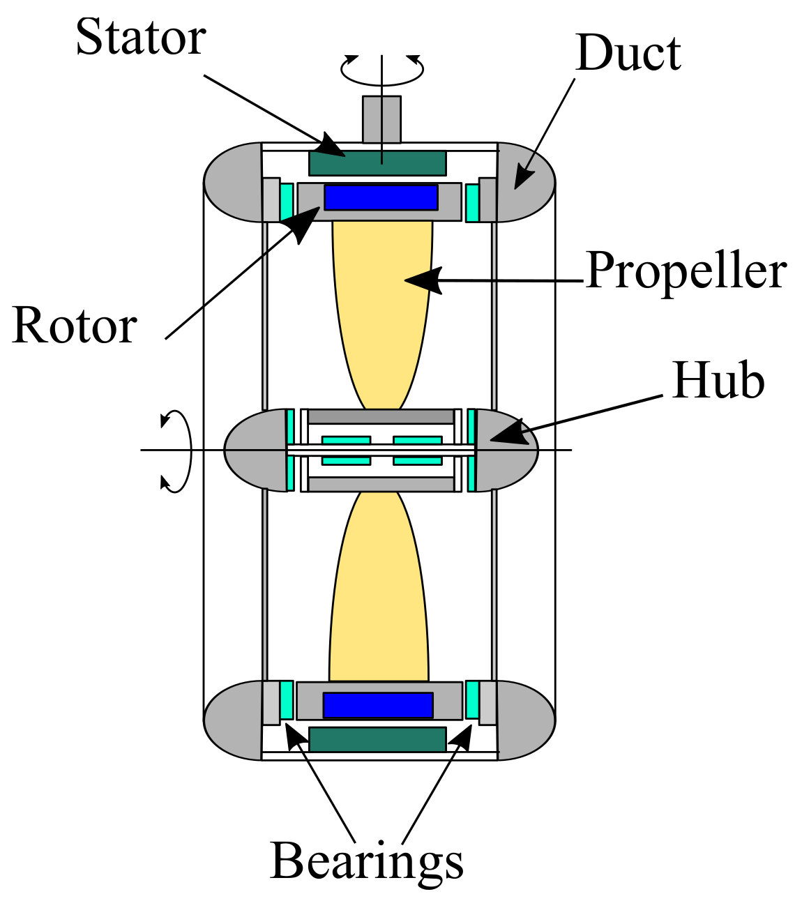
The electric rim-driven thruster is a ducted propeller that includes the electrical motor in the duct. The stator of the machine is integrated into the duct, and the rotor is built in a ring surrounding the propeller blades [12]. As a result, the electrical motor air-gap can be filled with seawater. Therefore, the active parts (windings, magnets, magnetic cores) are sealed with specific materials to protect them from corrosion [13]. However, seawater can contribute actively to the motor cooling, and the winding current density can be augmented easily [14]. The permanent magnet machines are used in rim-driven propulsors, especially the axial flux permanent magnet machines, which are characterized by high 3D electromagnetic effects [15,16]. Furthermore, rim-driven machines usually have a large diameter. However, these machines generally have a short axial length. The large diameter requires that the back-core radial depth should be as small as possible to avoid becoming overweight. These machines usually have to be operated at slow speeds, which requires a high number of poles, thus reducing the radial core depth and minimizing the weight and size of the machine [17].
Compared to the traditional electric podded propulsion system, the electric rim-driven propulsion system has certain advantages, such as better hydrodynamic efficiency, protection of the blades, and high power density [18]. Indeed, it provides a high degree of integration, and the cabin collapses the complicated propulsion shaft system, additional components, propulsion motors, and other equipment into a compact and weight-saving structure [19]. In addition, in rim-driven technology, a shaftless propeller can be used. This is a marine thruster that does not require a shaft or gearbox to transmit driving torque [20].
Thus far, most published works regarding the modeling and design of AFPM machines for rim-driven applications used numerical simulations with 3D finite element analysis (3D-FEA) [21,22], which is very expensive and time-consuming, especially when the accuracy of results is required [23]. To overcome this issue, some researchers have developed simple analytical models [10]; the authors designed and analyzed the performance of axial flux permanent magnet generators for rim-driven marine turbines. A comparative study was then made with a radial flux generator which was optimally designed with similar models and specifications. Additionally, multi-physic models (hydrodynamics, electromagnetic, and thermal) were developed and a method to couple them for the design of an integrated rim-driven tidal turbine system was presented in [13]. However, these two studies are based on analytical first-order electromagnetic models, which are not efficient for fully taking into account 3D effects. For validation purposes, the team of the French Naval Academy Research Institute in Brest, France, developed and tested a prototype of a rim-driven marine current turbine using a radial flux permanent magnet (RFPM) generator [24]. In other works, a rim driven motor with a Halbach array with uneven segments was optimized to maximize the electromagnetic torque. Moreover, a new kind of segmented Halbach permanent magnet motor for integrated motors was designed and fabricated in [25]. The motor has no bearings and employs a Halbach array in its rotor structure. Furthermore, the multicomponent fluid method is used to calculate the thermal and fluid field of the integrated motor propeller. In addition, the coreless, slotless, and slotted stators of an integrated motor were compared in [14]. Furthermore, the calculation and analysis of frictional losses on the motor rotor in the flow field of the space between the stator and the rotor of the Rim-driven motor were studied. The development of an efficient propulsion system and the design of the hub-less, rim-driven propeller through multidisciplinary integration (hydrodynamics, propeller shaping, electromagnetic, and drive circuits) were presented in [26]. The authors in [27] discussed the performance of slotless axial flux permanent magnet (AFPM) machines used for marine propulsion. A new modular arrangement of the machine’s stator winding was proposed, and experimental results were presented. In [28], the authors proposed a new electric motor topology, called ring winding AFPM, for the rim-driven thruster (RDT). They also presented a new method for determining the specifications of the electric motor, taking into account the propeller and the hull. The design methodology and constraints of the ring winding AFPM were also reported. A numerical simulation comparison of the hydrodynamic performance of a rim-driven propeller and a ducted propeller was performed in [29], using the same flow configuration, on a Ka-47 propeller inside a 19A duct. In addition, a comparison of open-water performance between hub-bed and unhub-bed rim-driven thrusters was carried out in [30] based on the computational fluid dynamics (CFD) method. The achieved results show that the hubless RDT has a higher efficiency than the hub-type RDT. The design and optimization of high-power-density PMSMs for podded propulsion systems were studied in [31]. The ship’s propeller characteristics were determined by parametric analysis considering the ship’s thrust requirements. Its configuration was optimized to ensure its high efficiency and to estimate the nominal engine power and torque.
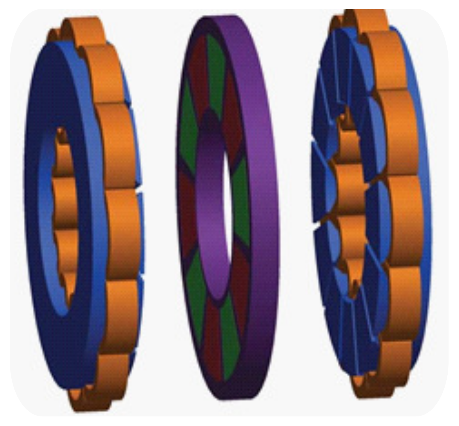
In this paper, an electric rim-driven propulsion system based on a double stator ironless rotor AFPM motor is optimally designed for practical naval specifications already used in a RFPM motor designed for a classical POD propeller. In a first step (described in Section 2), the hydrodynamic performance of the ship’s propeller is identified using parametric analysis and considering the propeller’s thrust, shaft power, and velocity requirements imposed within the specifications. Next, the propeller geometry is optimized to ensure its high efficiency, and the external diameter of the motor is evaluated. The second part of the paper describes the double stator ironless rotor AFPM machine and its main design parameters. Models which are used for the AFPM motor design are presented. Especially, the flux density in the air-gap is calculated using a fast 3D modeling method to evaluate the magnetic field in AFPM machines using a combination of magnetic charges concept, image theory, and 2D relative permeance functions. A design procedure is proposed based on an optimization algorithm. The proposed objective function, relevant constraints, and constant quantities are described. Then, the adopted motor AFPM design optimization algorithm is presented. In the last part, the optimized AFPM machine is compared to the RFPM machine designed earlier.
The main contribution of this paper is to propose a specific design method for AFPM machines used in RD propellers. This method used a fast dedicated electromagnetic model in an optimization procedure of the electrical motor taking into account rim-driven specifications and propeller hydrodynamic behavior.

2. Problem Specifications Description

In this paper, a reference classical pod with a three-phase radial flux permanent magnet (RFPM) motor propeller has been chosen as a specific comparative example for ship propulsion application [32]. The machine characteristics are presented in Table 1, The output power is selected to be 2100 kW at a nominal speed of 105 rpm.
The machine has 60 poles and 216 slots; therefore, the number of slots per pole and per phase is q = 6 / 5 . This yields a fractional-slot stator winding arrangement with a fundamental winding factor of 0.927. The rotor is made of fully pitched radial permanent magnets with a 1.17 T remanent magnetic flux density. The predicted time constant of the reference machine is about 0.112 s. For that value and the rated speed (150 rpm), a PWM frequency of 1 kHz is considered to ensure a low level of parasitic current for this speed range. The reference motor is used as a marine propulsion motor, and the achievement of high power density when a low-speed application is not considered as an easy. The presented paper aims to compare this reference solution with another structure based on the use of an AFPM motor included in a rim-driven propeller. This unconventional structure will be studied for the same operating point and optimized for these specifications.

3. Propeller Design Methodology

Naval electric propulsion systems consist of three essential parts: the power electronics stage, electric motors and propellers [7]. As the characteristics of the propeller associated with the PM motor studied in [32] are not known, this section will focus on the determination of a propeller design corresponding to the reference motor operating point. This propeller corresponds to the specification of a trampling cargo. The design of this propeller will provide dimensional constraints for the RD motor. Then, the choice and modeling of the electric motor designed for this application will be discussed.
In rim-driven structures, the rotor of the electrical motor is integrated with the propeller. The principal of a rim-driven thruster (AFPM motor and propeller) is shown in Figure 1.
At a given advance velocity V a , the propeller delivers the desired thrust T, and the motor will have to operate in a steady state to produce the input torque Q p and the propeller speed n p . In addition, the internal diameter of the motor will be fixed to be the blade’s external diameter D.
To determine the hydrodynamic performance characteristics of propellers, a method usually employed in propeller design and analysis consists of using non-dimensional propeller coefficients, namely the coefficient of advance ( J o ), the thrust coefficient ( K T ), the torque coefficient ( K Q ), and the propeller efficiency ( η p ). The performance of any designed or standard propeller can be easily obtained using these coefficients, which are expressed as follows [33]:
J o = V a n p D
K T = T ρ n p 2 D 4
K Q = Q p ρ n p 2 D 5
η p = J 2 π K T K Q
where ρ is the fluid density in kg/m 3 .
The values of these coefficients are determined by a reduced scale model test in a hydrodynamic basin or CFD calculation. In this study, it was decided to use a 4-blade-type Wageningen Ka 4-70 series propeller.
The performance of these specific ducted propellers was characterized in the Netherlands ship modeling basin [13]. 
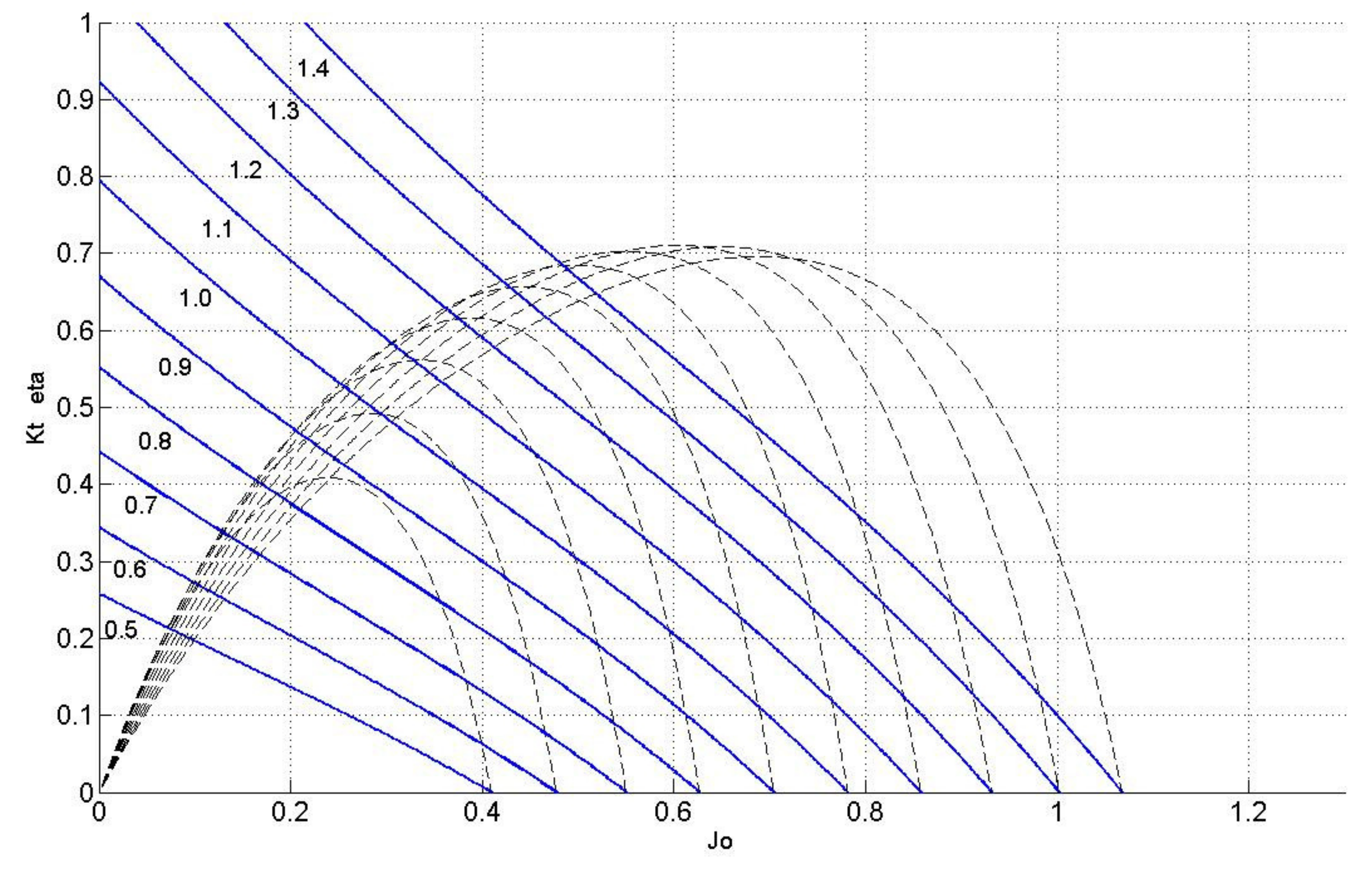
Figure 2 shows the thrust coefficient and efficiency curves of the Ka N19A series propeller with an area ratio A E / A 0 = 3 / 4 , and different values of reduced pitch ratios P / D from 0.5 to 1.4 .
The experimental curves of K T and K Q can be expressed quite accurately by polynomial functions in terms of the advance coefficient J o and the pitch ratio P / D as follows:
K T ( J 0 , P / D ) = i = 0 6 P D i j = 0 3 α i j J o j
K Q ( J 0 , P / D ) = i = 0 6 P D i j = 0 4 β i j J o j
where the coefficients α i j and β i j are constants presented in [34].
Generally, when designing a propeller, one takes a ship’s operating point (T and V a ) and deduces the performance of the required propeller ( Q p and n p ). However, in this study, the opposite path is followed; one takes a propeller operating point ( Q p and n p ) and deduces the ship’s advance speed and the most appropriate propeller that could produce the thrust imposed by the ship. The obtained propeller can then be associated with the reference POD motor or with the proposed AFPM motor in an RD structure.
The main specifications of the propeller are shown in Table 2. The requirements of the electric motor, such as output torque ( Γ o u t ), inner diameter ( D i ), and rotational speed (n) are considered equal to the propeller torque ( Q p ), propeller diameter (D), and propeller speed ( n p ), respectively.
The parameters considered fixed are Q p , n p and T, whereas V a , P / D , and D have to be determined. Their realistic ranges of values are presented in Table 3.
Knowing Q p , n p , T, V a , P / D , and D, it is then possible to calculate the torque coefficient K Q , the thrust coefficient K T , the advance coefficient J 0 , and the efficiency of the propeller η p . From Figure 2, it is clear that only one pitch ratio P / D is fitted to a realistic operating point ( J 0 , K T , K Q ) that satisfies Equations (1)–(3). Therefore, an iterative process can be used to find a relevant in terms of propeller efficiency. Once the right pitch ratio has been found, it is then possible to deduce the advance velocity V a , the efficiency η p , and the diameter of the propeller D from the model. The propeller diameter value is the main common dimension between the propeller and RD motor.
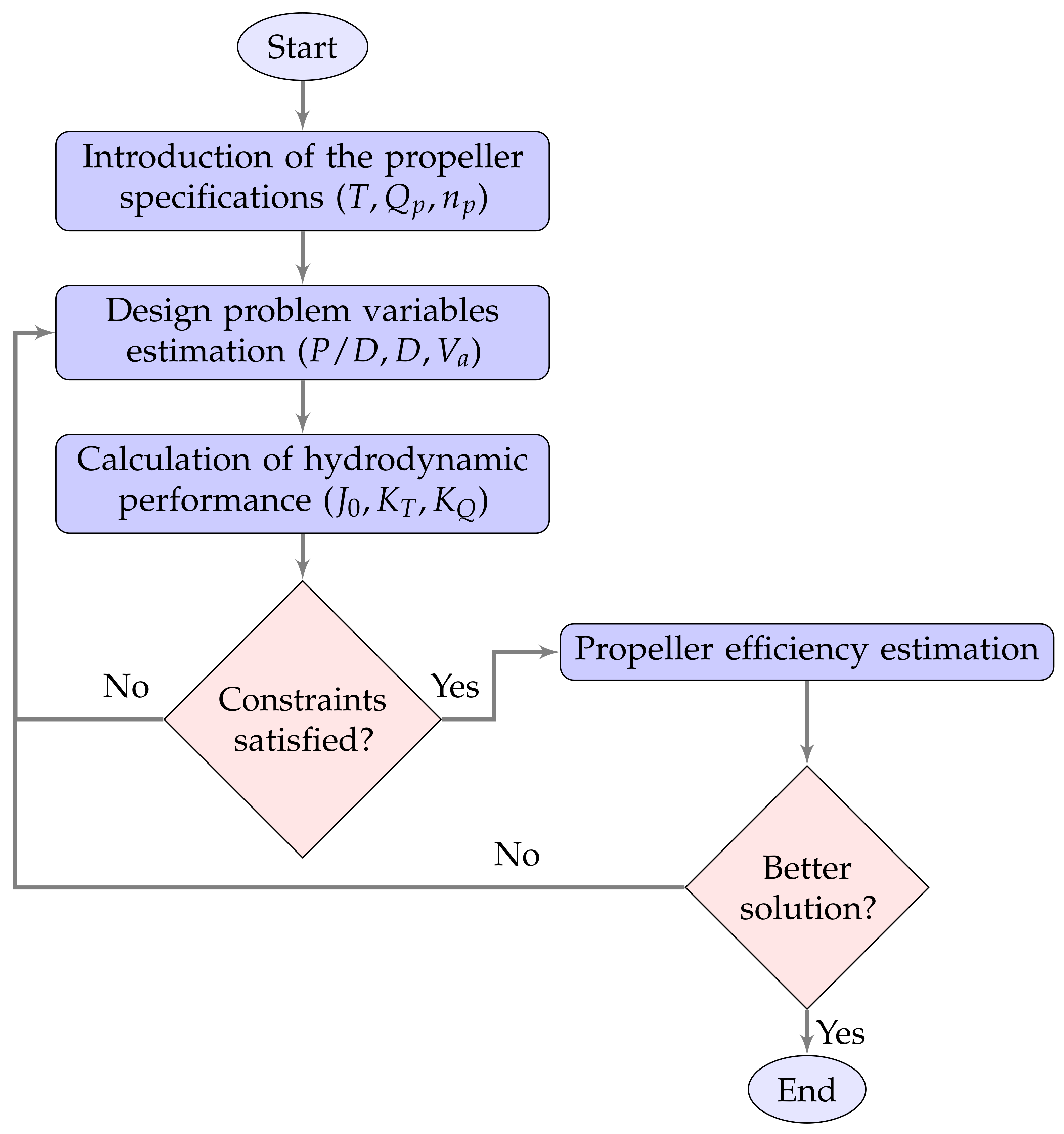
The propeller design and optimization procedure, which is presented in Figure 3, was followed to find the propeller operating point that satisfies the propeller specifications for which the hydrodynamic efficiency is maximum and to derive the propeller diameter value. The calculation method used a model of propeller that is well known in the field of propeller design. It is based on a set of typical ducted propeller data obtained from tests in ship model basins. The interest of this model is that it is of good accuracy as directly derived from tests. Furthermore, thanks to this non-dimensional approach, it is possible to deduce the performances of a propeller whatever its dimensions, which is particularly interesting in the case of a systematic design process.
The first step of the adopted methodology includes the introduction of the propeller specifications such as the thrust, torque, and rotational speed of the propeller, providing an estimation of the main variables of the propeller. In our case, these parameters are the advance velocity, the pitch ratio, and the diameter of the propeller; all of them have to be calculated by the applied iterative algorithm and then the search for the operating point. Finally, if the obtained point is an operating point, i.e., it satisfies Equations (1)–(3), its corresponding efficiency is calculated and compared with the efficiency obtained by a previous operating point, and the greatest of them is kept. The process is repeated until the maximum hydrodynamic efficiency is achieved.
The design and analysis of the propeller were completed. The hydrodynamic performances of the propeller corresponding to the optimal operating point are given in Table 4.
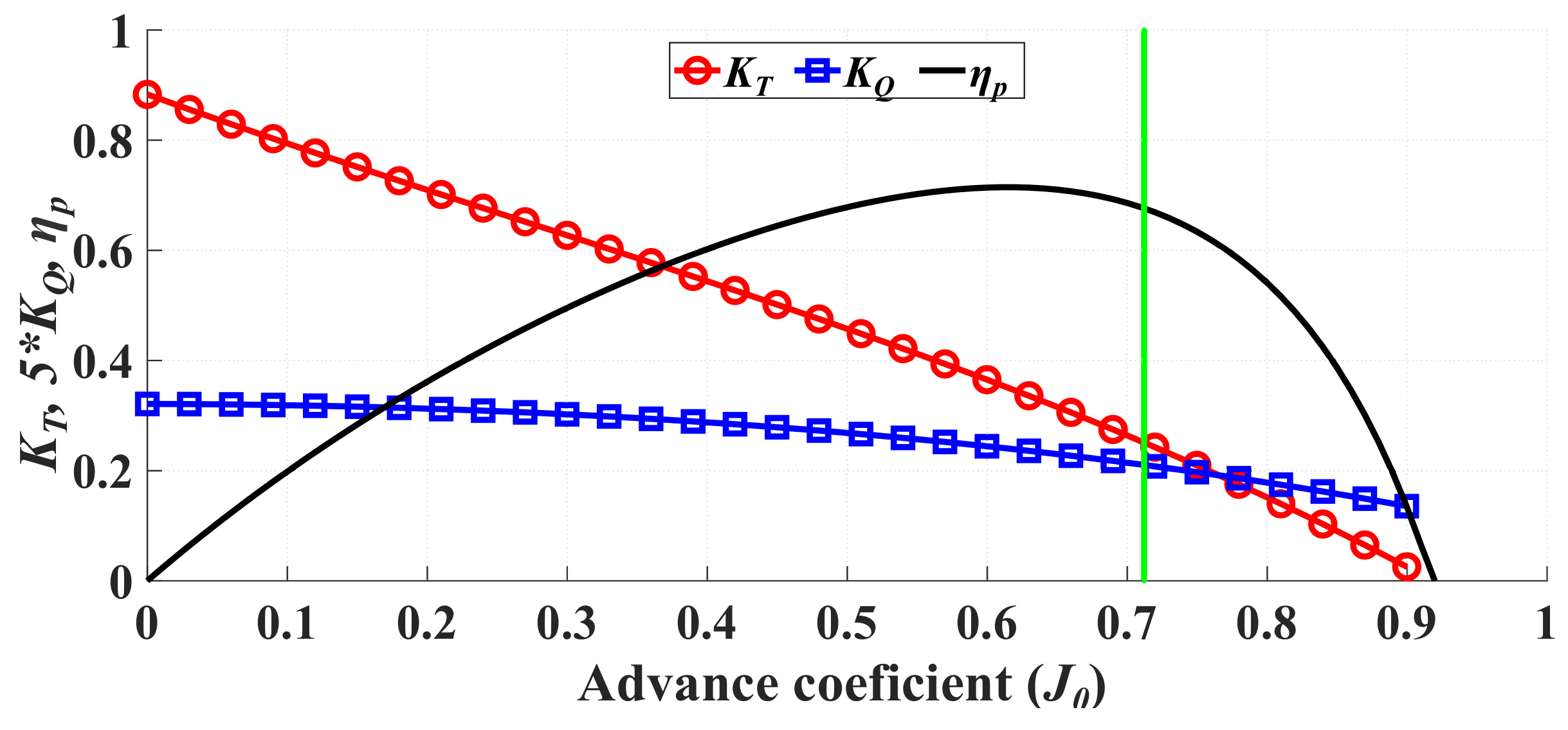
The hydrodynamic curve of the optimized propeller is shown in Figure 4. In this curve, the thrust coefficient ( K T ), the torque coefficient ( K Q ), and the propeller efficiency ( η p ) from Equations (4)–(6) are plotted as a function of the advance coefficient ( J 0 ). At the optimum operating point (marked on the curve), the designed propeller has an efficiency of 68.91%, which is quite satisfactory for such an application.

4. AFPM Machine Analysis and Design

4.1. Description of the Analyzed Machine

Marine propulsion motors have a significant effect on the overall performance of the ship’s power system, as already mentioned in [35]. In addition, the motor must have low back-EMF harmonics if a classical field-oriented control is used, as well as non-saturable material operation, acceptable thermal behavior, low cogging torque, and low torque ripple. To satisfy these requirements, a double stator AFPM motor with an ironless rotor is selected to be optimally designed. Several studies show that the double-sided AFPM configuration presents the highest level of torque density among various types of axial flux and radial flux PM machines [36]. This type of electrical machine is well known to be very useful for specific applications such as direct ship propulsion due to the very high power and torque densities [37]. The structure of this machine is shown in Figure 5; it comprises two stator disks, which are made with magnetic materials (soft magnetic composite (SMC), magnetic iron steel lamination, or both of them as a hybrid solution). Each stator disk supports three phases of independent winding, which are positioned in the stator slots.
The rotor is made of permanent magnets, which are arranged with alternating polarities around the circumference, and is centered between two iron stator cores. When the rotor remains perfectly centered, the axial forces exerted on the rotor disk are balanced, which allows for the minimization of the mechanical constraints, which is a key feature for AFPM machines. The modularity of this kind of machine where two independent stators are used allows for fault-tolerant operations and increases reliability. When a fault appears in one of the stator windings or cores, the system can be used at half power by disconnecting one of the two stators. The structure’s particular geometry also allows an easier heat dissipation of the stator losses. However, the main disadvantage of the AFPM structures is the mechanical stress due to the strong axial forces of magnetic origin exerted between the rotors and stators. Therefore, the mechanical design of such a machine often requires a complex assembly of the rotor and stator due to the attractive forces between the rotor and stator. They also require special machining of the slots for machines with stators containing ferromagnetic yokes. In addition, AFPM structures are mechanically more complex than RFPM machines. Therefore, the manufacture and assembly of axial flux machines are more delicate and require more structural materials [39].

4.2. Designed Machine Sizing Equations

4.2.1. Air-Gap Flux Density

In this study, the AFPM machine is modeled using a 3D fast and accurate magnetic field calculation tool, which has been presented in [38] by the same team. This method is based on a combination of magnetic charges concept, image theory, and relative permeance functions. This can take into consideration the significant 3D effects, such as curvature and edge effects, which are present in AFPM machines, as well as stator slotting effects. The flux density created by the whole rotor in the air-gap B g can be calculated by this method and is used to determine the main characteristics of the motor. It is assumed that non-linear phenomenon related to saturation of magnetic material are not taken into account.

4.2.2. Electromotive Force Computation

Through the knowledge of the axial flux density component B g / z in the air gap, the back-EMF can be calculated if the topology of the winding is known. Assuming that the conductors of winding ‘i’ are distributed in the slot opening areas in the form of a conductor angular density function, d c i ( φ ) , the back EMF, E i , corresponding to this winding can be computed as follows:
E i ( θ ) = p Ω ( t ) 0 2 π p R i R o ( B g / z ( r , φ , θ , z ) d c i ( φ ) r ) d r d φ
where p and Ω ( t ) are the number of pole pairs and mechanical speed of the rotor, respectively.

4.2.3. Computation of Electromagnetic Torque

The electromagnetic torque expression, Γ e l m can be deduced from the knowledge of the EMF wave-forms, the phase-related current “i”, and the number of phases “m” as:
Γ e l m ( t ) = 1 Ω ( t ) i = 1 m E i ( t ) i i ( t )

4.2.4. Inductances Computation

One of the most important parameters in the design and analysis of electrical machines is the inductances of the machine [40]. In considered AFPM synchronous machines, direct and quadrature axis synchronous inductances are equal as long as the rotor has no saliency. The direct axis synchronous inductance L s d consists of two main parts: the magnetizing inductance L m and the leakage inductance L l [41].
L s d = L m + L l
The magnetizing inductance can be given as a function of the average to the maximum value of gap flux density α i , the effective air gap δ e , the winding factor k w , the number of turns series per phase of one stator N p h , the average pole pitch τ p , and the effective length of the stator core in the radial direction L e as:
L m = 4 α i m p δ e μ 0 π k w N p h 2 τ p L e
where μ 0 is the magnetic permeability of the vacuum. The geometry and main dimensions of the studied AFPM machine are presented in Figure 6. The leakage inductance is introduced as the sum of other components, which are as a function of the machine geometrical parameters and the number of turns series per phase. It is calculated with the following equation:
L l = L l s l o t + L l t t + L l δ + L l E W
where L l s l o t , L l t t , L l δ , and L l E W are the slot leakage inductance, the tooth tip leakage inductance, the harmonic leakage inductance, and the endwinding leakage inductance. These leakage inductances are calculated using the classical formula, which can be found in [42].

4.2.5. Estimation of Iron Losses

Iron losses in synchronous electrical machines are essentially located in the stator yoke and teeth. The specific iron losses of standard F e S i sheets P f e can be estimated using the Steinmetz formula as [43]:
P F e = P F e 0 f f 0 1.5 B F e B F e 0 2.2
where f and B F e are, respectively, the frequency and the maximum flux density seen by the ferromagnetic lamination. P F e 0 (2.5 W/kg) is the value of the specific loss mass density established for the characteristic frequency f 0 (50 Hz) and the characteristic value of the induction B F e 0 (1.5 T).

4.2.6. Axial Length of the Back-Iron

The stator core axial length h y s , as shown in Figure 7, can be calculated considering a maximal flux density in the stator core to limit material saturation phenomena. That leads to:
h y s = ψ y R o R i B m a x
where ψ p = 2 ψ y is the magnetic flux per pole calculated by integrating the axial flux density over a pole pitch of the air-gap/stator contact surface. For the F e S i ferromagnetic lamination, a maximum flux density of 1.8 T is admissible.

4.2.7. Copper Losses

The copper losses in the stator conductors are estimated from the RMS value of the phase current I p h and one phase resistance R p h as follows:
P c o = 3 R p h I p h 2
The calculation of the phase resistance in AFPM machines is an approximation because the length of the end-windings is not perfectly known. Considering the shapes of the end-windings shown in Figure 8, the estimated length of a turn can be written as follows:
L t u r n = 2 L e + L i e n d + L o e n d = 2 L e + π 2 ( τ c i + τ c o )
where L i e n d and L o e n d are the lengths of the inside and outside end turns, respectively. τ c i and τ c o are the diameters of the half-circles that represent the inside and outside end turns, respectively.
The phase resistance can be then expressed as follows:
R p h = 2 ρ c u N p h 2 L t u r n k f A s
where ρ c u , k f and A s are the resistivity of the copper, the slot fill factor, and the slot cross area, which is divided by two because in each slot there are two layers of conductors.

4.2.8. Phase Voltage

The two stators are considered to be supplied by two independent converters, which are driven identically. The per-phase equivalent electrical circuit of an AFPM machine for motor mode is shown in Figure 9, in which V is the source supply voltage and L s ω is the synchronous reactance.
It is assumed that the motor is controlled with a maximum torque per ampere (MTPA) strategy (zero value of direct current). In this case, the value of the angle Ψ (phase shift between the fundamental of the electromotive force and the current) is null. Therefore, that leads to the phasor diagram of Figure 10. The phase voltage for the motor application is then expressed as follows:
V ¯ = E ¯ + R p h I p h ¯ + j L s ω I p h ¯

4.2.9. Power Factor

Based on the phasor diagram shown in Figure 10, the rated power factor of the studied AFPM machine is given by:
cos φ = E + R p h I p h ( E + R p h I p h ) 2 + ( L s ω I p h ) 2 )
where E is the RMS value of the electromotive force at the rated operating point.

4.2.10. Efficiency

Neglecting mechanical and parasitic losses, the overall efficiency of the motor can be expressed as follows:
η = P o u t P o u t + P F e + P c o

5. Optimization Problem Formulation

The design optimization was based on the modeling of the AFPM motor presented in Section 4. The inner radius was fixed before the optimization process started, which corresponds to the propeller diameter calculated from the iterative process described in Section 3. A non-linear optimization technique was used to solve the design optimization problem, taking into account relevant design constraints and objectives and determining an optimal set of geometrical parameters for the AFPM motor. The formulation of this problem will be presented in the next subsections.

5.1. Objective Function

The optimization of an AFPM machine can be considered as a non-linear constrained problem, which can be solved for different objective function formulations. For ship propulsion applications, it is necessary to estimate the cost of the studied machine, which depends mainly on the weight of its active materials, its structure cost, and its manufacturing cost, to compare the studied solution to other systems from an economical point of view. In this study, only the AFPM motor’s active materials (permanent magnet, copper, and iron) cost is considered. The objective function of this optimization step is then the sum of the costs of the three materials, which is defined as:
C = C P M W P M + C C u W C u + C F e W F e
where C P M , C C u , and C F e are the permanent magnet, the copper, and the iron specific costs, as listed in Table 5, and W P M , W C u , and W F e are the permanent magnet, the copper, and the iron mass, respectively. The cost of the AFPM motor is calculated only from the geometrical parameters, which allow calculating the volume and mass of each material.

5.2. Optimization Variables

Considering the model presented in previous section, nine optimization variables were chosen, including the outer diameter ( D o ) , the air-gap ( g ) , the magnet axial thickness ( h m ) , the slot width to slot pitch ratio ( β s ) , the slot depth in the axial direction ( h s ) , the winding current ( I p h ) , the magnet arc to pole ratio ( β m ) , the pole pair number ( p ) and the number of turns in series per phase ( n s ) .
X * = m i n X ϵ f ( X )
where X = ( D o , g , h m , β s , h s , I , α m , p , n s ) is a vector containing the independent variables, and is the space of possible solutions.

5.3. Optimization Constraints

The optimization problem includes several design constraints that guarantee the required electromagnetical, thermal and mechanical behaviors of the machine, which determine the set , and are listed in Table 6.
The first constraint is related to the heat dissipation abilities of the machine and therefore to the evaluation of the admissible losses and the rated current. The losses were assumed to be generated from the internal volume of the stator and dissipated from the stator external surfaces. This transfer is modeled by a heat transfer coefficient h [45]. A maximal heat flux per square meter of external stator surfaces was defined to limit the internal temperature to a tolerable value. The quantity of heat transfer is then proportional to the heat transfer coefficient h, the temperature difference Δ T and the external surface S e x t , as shown in Figure 11. The relation between losses, P l o s s and temperature difference, Δ T , is then expressed as follows:
P l o s s = h S e x t Δ T
In this study, it was assumed that the reference machine and the optimized AFPM machine have the same type of cooling. Therefore, they have the same heat transfer coefficient h, so it is sufficient to compare the ratio between the total loss and the external surface of the machine.
Δ T = P l o s s / h S e x t
In the majority of cases, the operating frequency should be as low as possible to reduce the motor core losses. Therefore, the upper limit of this parameter was set at 150 Hz. This requires that the search space for the number of pole pairs ( p ) should be between 20 and 45. Additionally, The maximum permissible flux densities in the teeth and stator yoke were set at 1.8 T to avoid material saturation and reduce iron losses. In addition, there was a current limit of 4.5 kA related to the properties of the inverter, which defines the maximum value of the current that the motor could absorb. The maximum magnetic field H m a x ( X ) was limited to be smaller than the permanent magnet coercive field to prevent any potential demagnetization. Therefore, high-energy N d F e B magnets were selected, with a remanent flux density value of 1.23 T. In addition, constraints related to the manufacturability of the machine were introduced. The relative slot opening (i.e., the slot opening to the tooth pitch ratio) was chosen to be between 50 % and 70 % . In addition, the conductors must be able to be easily placed in the slots. In general, flat copper conductors are used for this type of machine. Therefore, the width of the slot opening ( b s 0 ) should be greater than the dimensions of the used wires. However, a higher slot opening will negatively affect the cogging torque and flux leakage and should be well chosen. In addition, a fractional slot winding with a double layer configuration was chosen to be studied in this work. This configuration allows minimizing the end-windings to increase efficiency and compactness. Thus, the number of slots per pole and phase was set to 0.5 . The AFPM motor power factor was considered to be greater than 0.9 with an efficiency greater than 95 % . The torque ripple developed by the machine was limited to 10% to reduce mechanical vibration on output performance. In addition, trapezoidal magnets were used because this geometry favors a minimal torque ripple in AFPM machines [46].

6. Optimization Results and Discussion

The objective of this section is to investigate the performance of the optimal double stator AFPM motor and to compare it with the reference radial flux PM motor, taking into account the specifications listed in Table 6 and the proposed models and methodology presented in Section 4. An optimization process is performed using genetic algorithm. This optimization algorithm is known as the GA function in MATLAB. This algorithm has successfully converged into an optimal design that satisfies all the imposed constraints. The main dimensions and performance characteristics of the optimized double stator AFPM motor are summarized in Table 7 and Table 8, respectively.
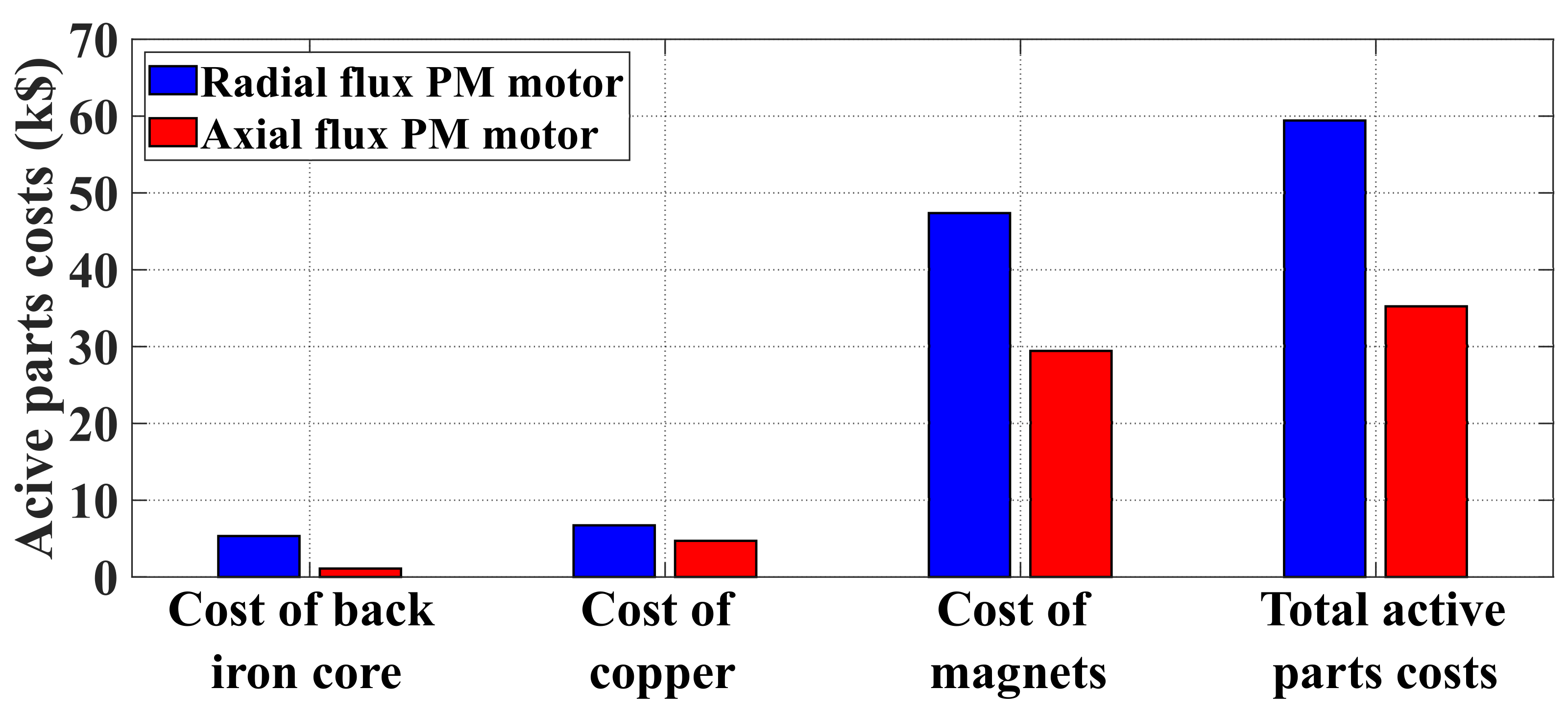
According to Figure 12, the estimated total cost of the active materials of the optimized double stator AFPM motor is equal to 35,323$. This value is lower than that corresponding to the total active parts cost of the reference RFPM machine, which is 59,424
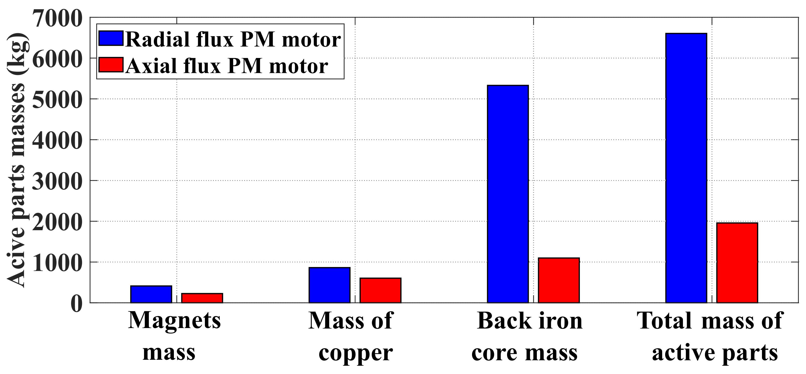
$. A reduction of about 40.55% has been achieved. This shows that the design and optimization procedure followed seems to have achieved its main objective, i.e., the reduction of the total active parts cost of the double stator AFMP machine. Regarding the mass comparison, the double stator AFPM motor presents a reduction in the active parts mass of about 70% compared to the total active parts mass of the RFPM machine as shown in Figure 13. Regarding the electromechanical performance of the designed AFPM motor, a very satisfactory torque density of 97.6 Nm/kg has also been achieved. This value is higher than the torque density of the RFPM motor, which is equal to 28.9 Nm/kg. In addition, the better compactness of the double-stator machine is due to the presence of a double air-gap. The use of an ironless rotor also contributes to the reduction of the iron mass. It can also be seen that for the AFPM machine, the copper mass is reduced by about 30% compared to the RFPM machine. In the AFPM machine, 10% of copper is located in the coil ends. This can be explained by its very low active length and the use of a more appropriate winding such as fractional slots winding ( q = 0.5 ) , which has allowed a significant gain in the volume of copper in the endwindings and an improvement in terms of efficiency. However, in this study, the masses and costs of the inactive materials used to ensure the mechanical performance of these motors as well as the manufacturing and assembly costs are not taken into account. Generally, axial flux magnetic structures are mechanically more complex than radial flux machines. Their manufacture and assembly are therefore more delicate and require more structural materials. This leads to additional costs and masses, which have not been evaluated in this comparative study.
The optimized AFPM motor has an efficiency and power factor of 97.95% and 0.96, respectively. Furthermore, at nominal operation, the single-phase current absorbed by the motor is equal to 561 A, with a current density of 2.53 A/mm 2 . This low value can be explained by the presence of two stators, which allows segmentation of the power between the stators. Therefore, if a fault occurs in one of the stator windings or stator cores, the machine can be operated at half power by disconnecting one of the stators.
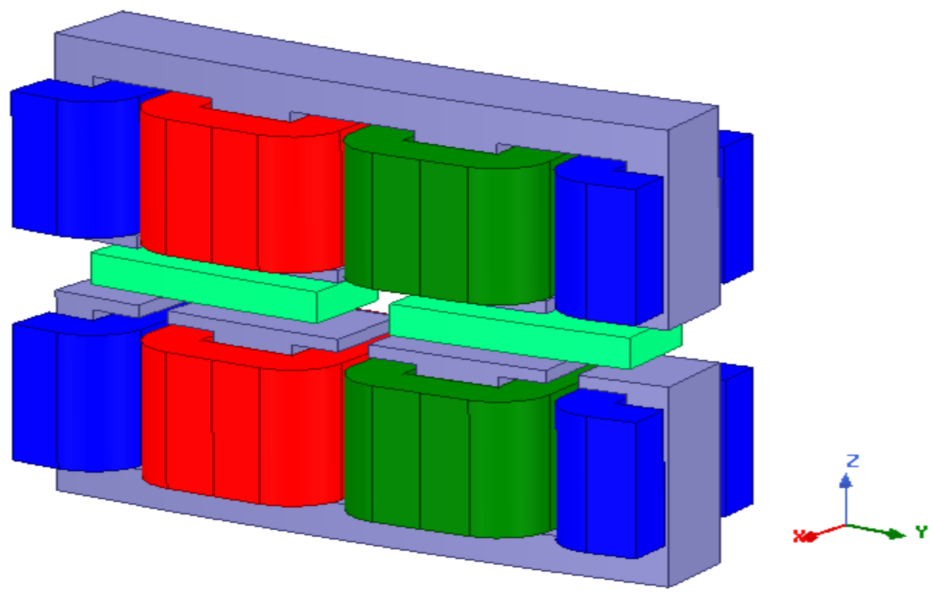
To confirm the validity of the optimal rim-driven AFPM motor’s EM behavior, a 3D finite element analysis (3DFEA) is carried out using the commercial software ANSYS (Figure 14 presents the 3D geometry of the motor). 
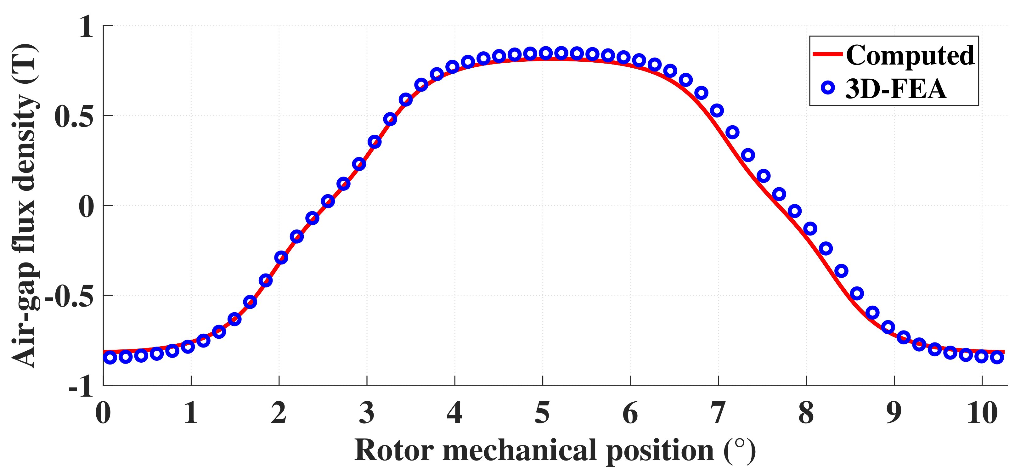
Figure 15 shows the axial magnetic flux density distribution in the middle of the air gap at the mean radius, obtained from the model used for the design process and 3D-FEA at no-load conditions. The obtained results demonstrate good agreement beetwen numerical and analytical models.
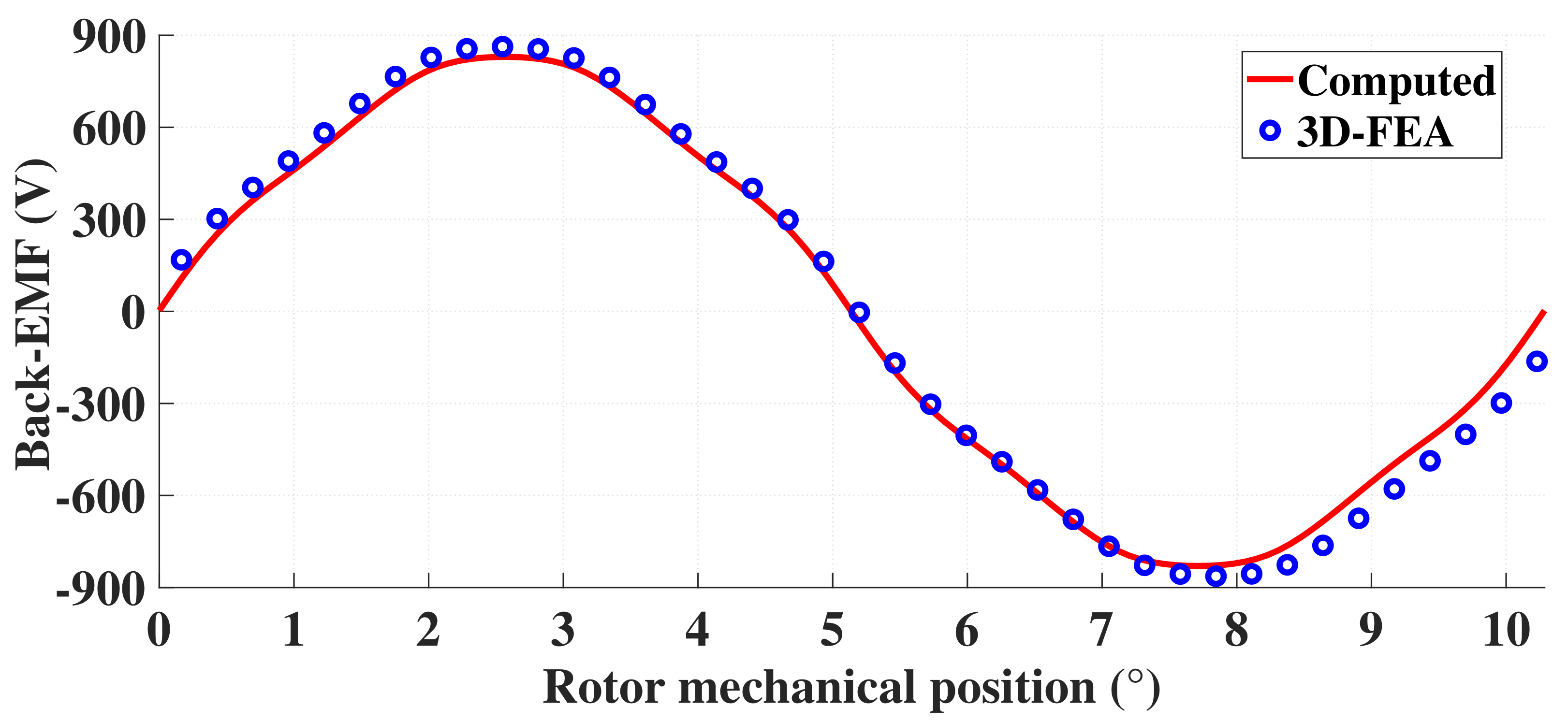
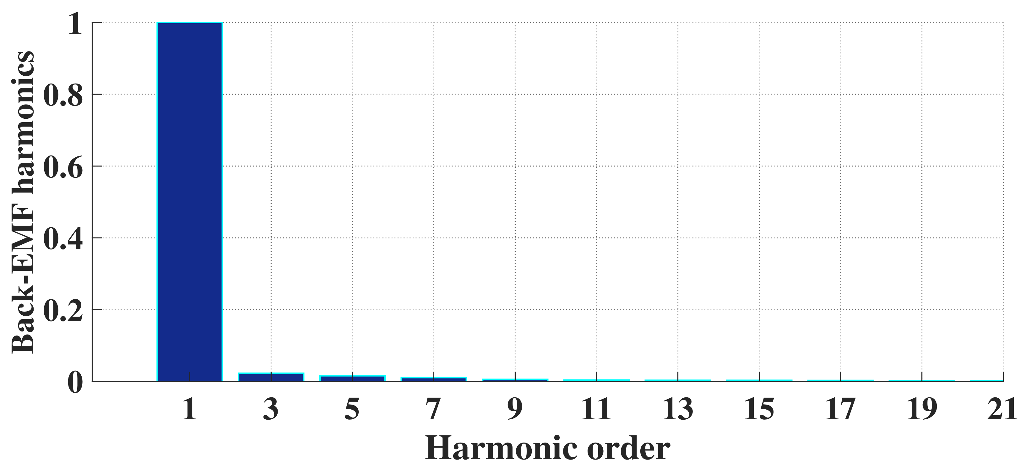
The back-EMF variation as a function of rotor angle is shown in 
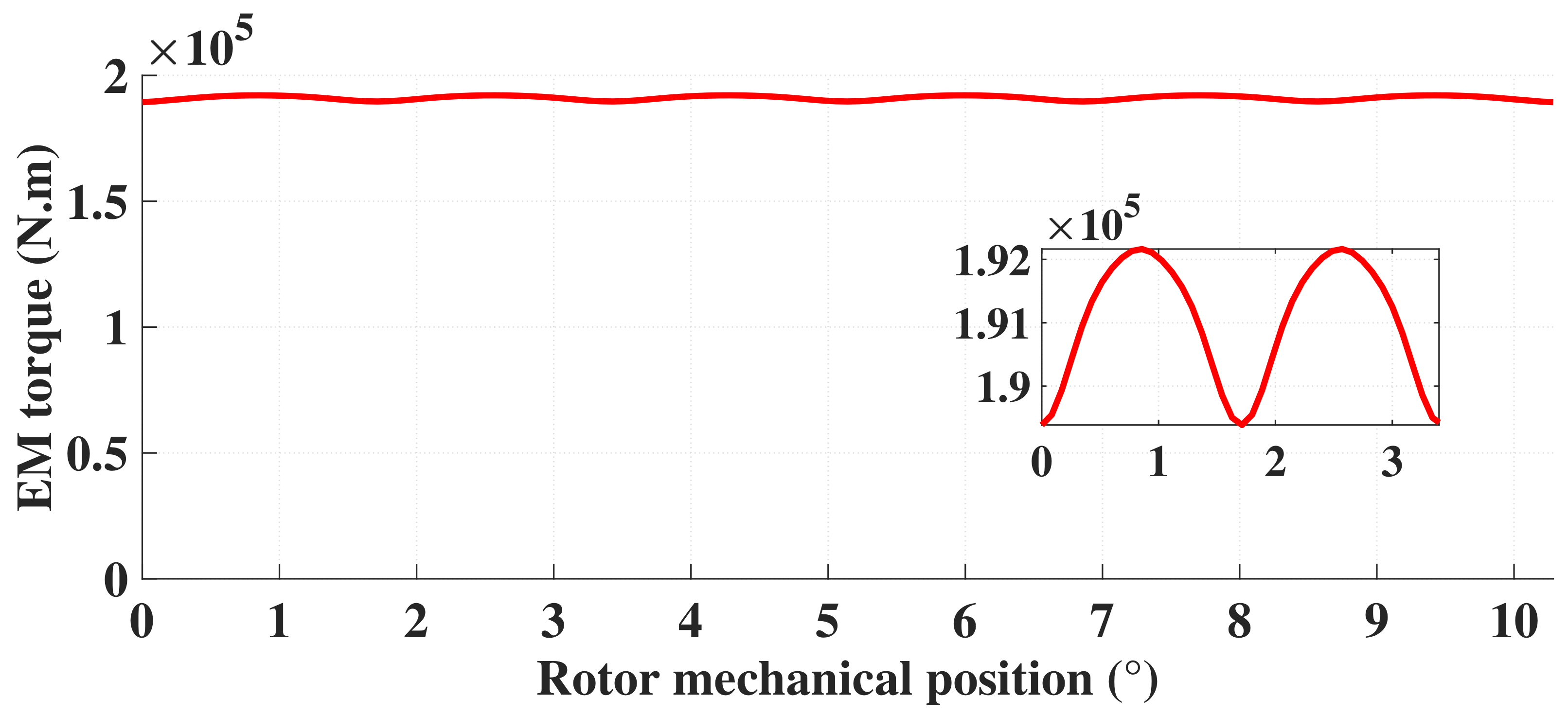
Figure 16. The back EMF calculated with the model used for the design is in very good agreement with the 3D-FEM computation. Furthermore, both axial flux density and back EMF have a sinusoidal profile and a low level of harmonic content (THD = 3.1%) as shown in Figure 17. This leads to a low motor torque ripple value, as illustrated in Figure 18.
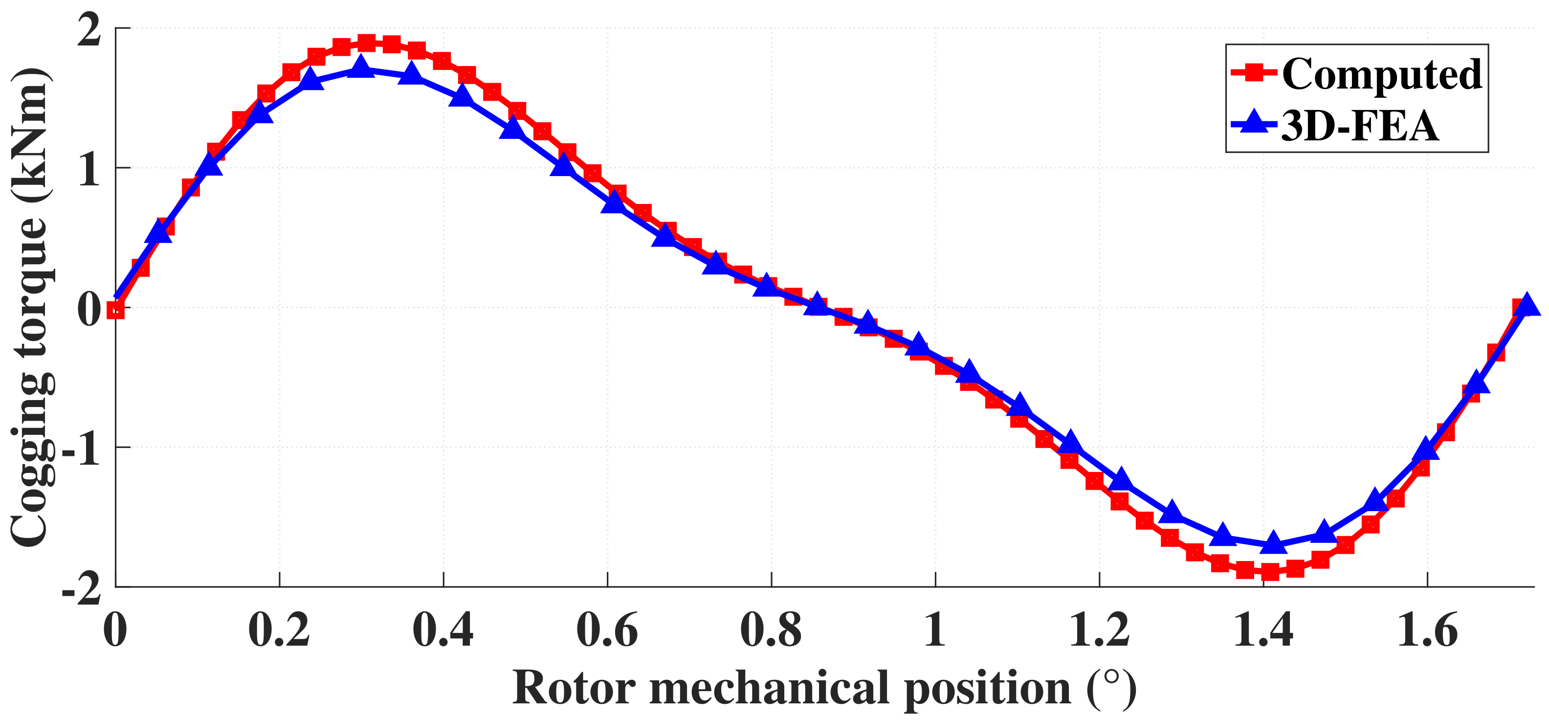
Figure 19 shows the profile of the cogging torque, which was evaluated by estimating the differential magnetic pressure, as a function of the mechanical position of the rotor [38].
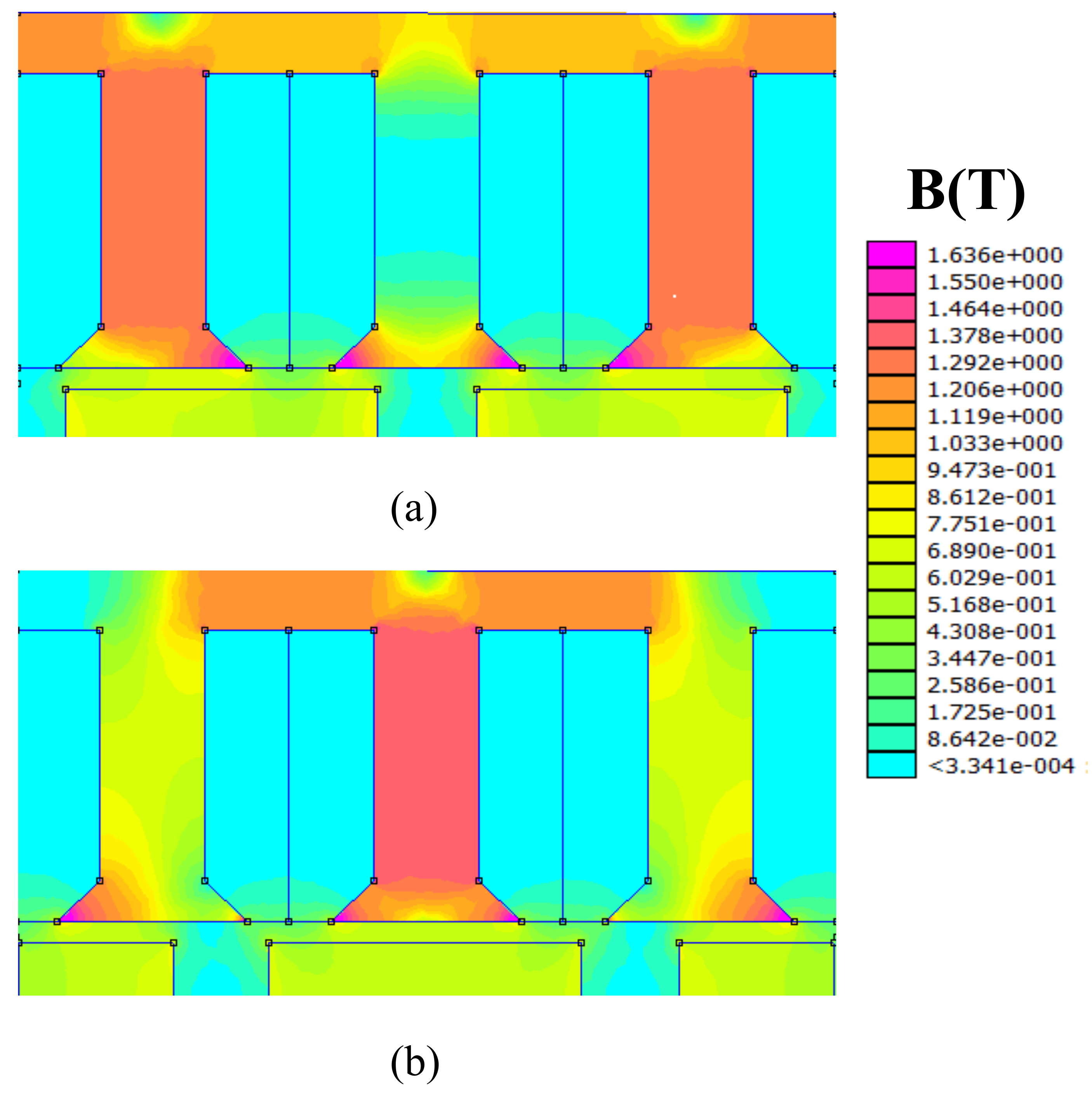
The calculated cogging torque is also in good agreement with the 3D-FEM simulation. It can be seen that the maximum amplitude of the cogging torque is equal to 0.89% of the rated torque, which can be regarded as a low quantity in comparison with the rated torque developed by the machine. Based on the previous factors, it seems that the optimized AFPM motor will have good behavior in terms of vibration and noise. Moreover, the mapping of the flux density distribution over the different parts of the optimized AFPM motor obtained by the 2D-FEA for different positions of the magnet center, as shown in Figure 20, indicates that the rim-driven AFPM motor’s stators core are not saturated during their operation.

7. Conclusions

In this paper, the design and optimization procedure of a double-stator AFPM motor for a high-power naval rim-driven propulsion system is presented and discussed. First, the design specifications of a RFPM motor used for naval propulsion found in the literature are taken as a reference. Then, considering the requirements of the ship, a relevant propeller is designed. Next, sizing models are described based on a fast and accurate 3D tool for the calculation of the magnetic field in AFPM machines and are integrated into an optimal design process that allows an optimal design of AFPM motors. This process minimizes the cost of active parts and takes into consideration the constraints of the motor characteristics imposed by the application and the considered system configuration. The resulting designed AFPM motor is validated by 3D-FEA simulations. A comparison of the two topologies (AFPM and RFPM motors) is conducted and mainly shows that the double stator axial flux permanent magnet motor has a lower active material cost, lower mass, better thermal performance, higher efficiency and power factor, non-saturable operation, low current density, low cogging torque, and low torque ripple. Future improvements to the model should include other models that would represent other physical phenomena, such as structural distortion or viscous torque in the air-gap, as well as the development of a more comprehensive propeller model, suitable for a more accurate optimization process, that may influence the performance of the machine.

Author Contributions

Conceptualization, H.O., J.-F.C. and M.B.; methodology, H.O. and J.-F.C.; software, H.O. and Y.A.; validation, H.O. and J.-F.C.; formal analysis, H.O., J.-F.C., F.K., A.Z., Y.A. and M.B.; investigation, H.O. and J.-F.C.; writing—original draft preparation, H.O.; writing—review and editing, J.-F.C., F.K., A.Z., Y.A. and M.B.; supervision, J.-F.C. and F.K. All authors have read and agreed to the published version of the manuscript.

Funding

This research received no external funding.

Conflicts of Interest

The authors declare no conflict of interest.

References

  1. Lee, C.; Kim, J. Energy Efficient Control for Electric Ship Propulsion Considering Thrust Fluctuation in Regular Waves. IFAC-PapersOnLine 2021, 54, 364–369. [Google Scholar] [CrossRef]
  2. Inal, O.B.; Charpentier, J.F.; Deniz, C. Hybrid power and propulsion systems for ships: Current status and future challenges. Renew. Sustain. Energy Rev. 2022, 156, 111965. [Google Scholar] [CrossRef]
  3. Propulsion Systems Used in Modern Naval Vessels. Available online: https://navalpost.com/propulsion-systems-navies-gas-diesel-electric/ (accessed on 8 March 2021).
  4. Nuchturee, C.; Li, T.; Xia, H. Energy efficiency of integrated electric propulsion for ships—A review. Renew. Sustain. Energy Rev. 2020, 134, 110145. [Google Scholar] [CrossRef]
  5. Kirtley, J.L.; Banerjee, A.; Englebretson, S. Motors for ship propulsion. Proc. IEEE 2015, 103, 2320–2332. [Google Scholar] [CrossRef]
  6. He, Y.; Fan, A.; Wang, Z.; Liu, Y.; Mao, W. Two-phase energy efficiency optimisation for ships using parallel hybrid electric propulsion system. Ocean Eng. 2021, 238, 109733. [Google Scholar] [CrossRef]
  7. Nounou, K.; Charpentier, J.F.; Marouani, K.; Benbouzid, M.; Kheloui, A. Fault-Tolerant Control of VSI Driven Double Star Induction Machine for Electric Naval Propulsion. In Proceedings of the 2018 IEEE International Power Electronics and Application Conference and Exposition (PEAC), Shenzhen, China, 4–7 November 2018; IEEE: Piscataway, NJ, USA, 2018; pp. 1–6. [Google Scholar]
  8. Bal, Ş.; Güner, M. Performance analysis of podded propulsors. Ocean Eng. 2009, 36, 556–563. [Google Scholar] [CrossRef]
  9. Yan, X.; Liang, X.; Ouyang, W.; Liu, Z.; Liu, B.; Lan, J. A review of progress and applications of ship shaft-less rim-driven thrusters. Ocean Eng. 2017, 144, 142–156. [Google Scholar] [CrossRef]
  10. Djebarri, S.; Charpentier, J.F.; Scuiller, F.; Benbouzid, M. Design and performance analysis of double stator axial flux PM generator for rim driven marine current turbines. IEEE J. Ocean. Eng. 2015, 41, 50–66. [Google Scholar]
  11. Gaggero, S. Numerical design of a RIM-driven thruster using a RANS-based optimization approach. Appl. Ocean Res. 2020, 94, 101941. [Google Scholar] [CrossRef]
  12. Dubas, A.J.; Bressloff, N.; Sharkh, S. Numerical modelling of rotor–stator interaction in rim driven thrusters. Ocean Eng. 2015, 106, 281–288. [Google Scholar] [CrossRef] [Green Version]
  13. Drouen, L.; Charpentier, J.F.; Clenet, S.; Semail, E.; Hauville, F. A coupled electromagnetic/hydrodynamic model for the design of an integrated rim-driven naval propulsion system. In Proceedings of the ElectrIMACS, Quebec, QC, Canada, 8–11 June 2008. [Google Scholar]
  14. Cheng, B.; Pan, G.; Cao, Y. Analytical design of the integrated motor used in a hubless rim-driven propulsor. IET Electr. Power Appl. 2019, 13, 1255–1262. [Google Scholar] [CrossRef]
  15. Li, J.; Yang, G.; Rao, F. Analysis and Design of Novel Axial Field Flux-Modulation Permanent Magnet Machines for Direct Drive Application. Machines 2022, 10, 495. [Google Scholar] [CrossRef]
  16. Tiegna, H.; Amara, Y.; Barakat, G. Overview of analytical models of permanent magnet electrical machines for analysis and design purposes. Math. Comput. Simul. 2013, 90, 162–177. [Google Scholar] [CrossRef]
  17. Djebarri, S.; Charpentier, J.F.; Scuiller, F.; Benbouzid, M.; Guemard, S. Rough design of a double-stator axial flux permanent magnet generator for a rim-driven marine current turbine. In Proceedings of the 2012 IEEE International Symposium on Industrial Electronics, Hangzhou, China, 28–31 May 2012; IEEE: Piscataway, NJ, USA, 2012; pp. 1450–1455. [Google Scholar]
  18. Lea, M.; Thompson, D.; Blarcom, B.; Eaton, J.; Friesch, J.; Richards, J. Scale model testing of a commercial rim-driven propulsor pod. J. Ship Prod. 2003, 19, 121–130. [Google Scholar] [CrossRef]
  19. Li, Q.; Abdullah, S.; Rasani, M.R.M. A Review of Progress and Hydrodynamic Design of Integrated Motor Pump-Jet Propulsion. Appl. Sci. 2022, 12, 3824. [Google Scholar] [CrossRef]
  20. Tan, W.; Yan, X.; Liu, Z.; Zhang, C.; Huang, Q.; Tian, Z. Technology development and prospect of shaftless rim-driven propulsion system. J. Wuhan Univ. Technol. 2015, 39, 601–605. [Google Scholar]
  21. Pan, G.; Cheng, B.; Zhang, P.; Cao, Y. Coupling design and performance analysis of rim-driven integrated motor propulsor. In Proceedings of the OCEANS 2016-Shanghai, Shanghai, China, 10–13 April 2016; IEEE: Piscataway, NJ, USA, 2016; pp. 1–6. [Google Scholar]
  22. Yakovlev, A.Y.; Sokolov, M.A.; Marinich, N.V. Numerical design and experimental verification of a rim-driven thruster. In Proceedings of the Second International Symposium on Marine Propulsors, Hamburg, Germany, 15–17 June 2011; pp. 396–403. [Google Scholar]
  23. Charpentier, J.; Scuiller, F. 3D Fast Calculation of Double Stator Axial Flux PM Machines with Ironless Rotor: Experimental Validation. In Proceedings of the 2018 XIII International Conference on Electrical Machines (ICEM), Alexandroupoli, Greece, 3–6 September 2018; IEEE: Piscataway, NJ, USA, 2018; pp. 11–17. [Google Scholar]
  24. Fleurot, E. Etude de Machines à Structures Non Conventionnelles Destinées à la Propulsion Navale et aux Énergies Marines. Ph.D. Thesis, Université de Bretagne occidentale, Brest, France, 2020. [Google Scholar]
  25. Liang, J.; Zhang, X.; Qiao, M.; Zhu, P.; Cai, W.; Xia, Y.; Li, G. Optimal design and multifield coupling analysis of propelling motor used in a novel integrated motor propeller. IEEE Trans. Magn. 2013, 49, 5742–5748. [Google Scholar] [CrossRef]
  26. Hsieh, M.F.; Chen, J.H.; Yeh, Y.H.; Lee, C.L.; Chen, P.H.; Hsu, Y.C.; Chen, Y.H. Integrated design and realization of a hubless rim-driven thruster. In Proceedings of the IECON 2007-33rd Annual Conference of the IEEE Industrial Electronics Society, Taipei, Taiwan, 5–8 November 2007; IEEE: Piscataway, NJ, USA, 2007; pp. 3033–3038. [Google Scholar]
  27. Caricchi, F.; Crescimbini, F.; Honrati, O. Modular axial-flux permanent-magnet motor for ship propulsion drives. IEEE Trans. Energy Convers. 1999, 14, 673–679. [Google Scholar] [CrossRef]
  28. Ojaghlu, P.; Vahedi, A. Specification and design of ring winding axial flux motor for rim-driven thruster of ship electric propulsion. IEEE Trans. Veh. Technol. 2018, 68, 1318–1326. [Google Scholar] [CrossRef]
  29. Liu, B.; Vanierschot, M. Numerical Study of the Hydrodynamic Characteristics Comparison between a Ducted Propeller and a Rim-Driven Thruster. Appl. Sci. 2021, 11, 4919. [Google Scholar] [CrossRef]
  30. Song, B.W.; Wang, Y.J.; Tian, W.L. Open water performance comparison between hub-type and hubless rim driven thrusters based on CFD method. Ocean Eng. 2015, 103, 55–63. [Google Scholar] [CrossRef]
  31. Chasiotis, I.D.; Karnavas, Y.L. A Study on Design and Optimization of High Power Density PMSM for Pod Propulsion System. In Proceedings of the 2018 XIII International Conference on Electrical Machines (ICEM), Alexandroupoli, Greece, 3–6 September 2018; IEEE: Piscataway, NJ, USA, 2018; pp. 534–540. [Google Scholar]
  32. Scuiller, F.; Semail, E.; Charpentier, J.F.; Letellier, P. Multi-criteria-based design approach of multi-phase permanent magnet low-speed synchronous machines. IET Electr. Power Appl. 2009, 3, 102–110. [Google Scholar] [CrossRef]
  33. MacKenzie, P.; Forrester, M. Sailboat propeller drag. Ocean Eng. 2008, 35, 28–40. [Google Scholar] [CrossRef] [Green Version]
  34. Drouen, L. Machines Électriques Intégrées à des Hélices Marines: Contribution à une Modélisation et Conception Multi-Physique. Ph.D. Thesis, The French Naval Academy Research Institute (IRENAV), Brest, France, 2010. [Google Scholar]
  35. Michalopoulos, P.; Kanellos, F.D.; Tsekouras, G.J.; Prousalidis, J.M. A method for optimal operation of complex ship power systems employing shaft electric machines. IEEE Trans. Transp. Electrif. 2016, 2, 547–557. [Google Scholar] [CrossRef]
  36. Rostami, N.; Feyzi, M.R.; Pyrhonen, J.; Parviainen, A.; Niemela, M. Lumped-parameter thermal model for axial flux permanent magnet machines. IEEE Trans. Magn. 2012, 49, 1178–1184. [Google Scholar] [CrossRef]
  37. Saavedra Ordóñez, H.; Riba Ruiz, J.R.; Romeral Martínez, J.L. Multi-objective optimal design of a five-phase fault-tolerant axial flux PM motor. Adv. Electr. Comput. Eng. 2015, 15, 69–76. [Google Scholar] [CrossRef] [Green Version]
  38. Ouldhamrane, H.; Charpentier, J.F.; Khoucha, F.; Zaoui, A.; Achour, Y.; Benbouzid, M. Development and experimental validation of a fast and accurate field calculation tool for axial flux permanent magnet machines. J. Magn. Magn. Mater. 2022, 552, 169105. [Google Scholar] [CrossRef]
  39. McDonald, A.; Mueller, M.; Polinder, H. Structural mass in direct-drive permanent magnet electrical generators. IET Renew. Power Gener. 2008, 2, 3–15. [Google Scholar] [CrossRef]
  40. Fei, W.Z. Permanent Magnet Synchronous Machines with Fractional Slot and Concentrated Winding Configurations. Ph.D. Thesis, Cranfield University, Cranfield, UK, 2011. [Google Scholar]
  41. Habibinia, D.; Feyzi, M.; Rostami, N. A new method for computation of axial flux permanent magnet synchronous machine inductances under saturated condition. J. Oper. Autom. Power Eng. 2018, 6, 208–217. [Google Scholar]
  42. Jokinen, T.; Hrabovcova, V.; Pyrhonen, J. Design of Rotating Electrical Machines; John Wiley & Sons: Hoboken, NJ, USA, 2013. [Google Scholar]
  43. Li, H.; Chen, Z.; Polinder, H. Optimization of multibrid permanent-magnet wind generator systems. IEEE Trans. Energy Convers. 2009, 24, 82–92. [Google Scholar] [CrossRef]
  44. Djebarri, S. Contribution à la Modélisation et à la Conception Optimale de Génératrices à Aimants Permanents Pour Hydroliennes. Ph.D. Thesis, Université de Bretagne Occidentale, Brest, France, 2015. [Google Scholar]
  45. Martin, R. Axial Flux Permanent Magnet Machines for Direct Drive Applications. Ph.D. Thesis, Durham University, Durham, UK, 2007. [Google Scholar]
  46. Saavedra, H.; Romeral, L.; Riba, J.R. Optimal design of a three-phase AFPM for in-wheel electrical traction. In Proceedings of the 2014 IEEE International Electric Vehicle Conference (IEVC), Greenville, SC, USA, 17–19 December 2014; IEEE: Piscataway, NJ, USA, 2014; pp. 1–7. [Google Scholar]
Figure 1. Rim-driven thruster schematic layout, adapted with permission from Ref. [9], 2017, Elsevier.
Machines 10 00932 g001
Figure 2. Wageningen Ka series propellers 4 blades, A E / A 0 = 3 / 4 and P / D = 0.5 1.4 adapted with permission from Ref. [34], 2010, IRENAV.
Machines 10 00932 g002
Figure 3. Propeller design and optimization procedure flowchart.
Machines 10 00932 g003
Figure 4. Propeller efficiency, thrust, and torque coefficients as a function of advanced ratio.
Machines 10 00932 g004
Figure 5. Double stator AFPM motor with ironless rotor structure, reprinted with permission from Ref. [38], 2022, Elsevier.
Machines 10 00932 g005
Figure 6. Geometry and main dimensions of the double stator AFPM motor.
Machines 10 00932 g006
Figure 7. Magnetic flux path in a portion of the stator armature pole of an AFPM machine.
Machines 10 00932 g007
Figure 8. Geometry of a coil of the stator disk.
Machines 10 00932 g008
Figure 9. Per-phase equivalent electrical circuit of AFPM machine.
Machines 10 00932 g009
Figure 10. Phasor diagram for non-salient AFPM machines.
Machines 10 00932 g010
Figure 11. Structure illustration of a conventional RF machine compared to an AF machine.
Machines 10 00932 g011
Figure 12. Comparison of the costs of double stator AFPM and RFPM motors’ active parts.
Machines 10 00932 g012
Figure 13. Comparison of the masses of double stator AFPM and RFPM motors’ active parts.
Machines 10 00932 g013
Figure 14. 3D geometry of the AFPM.
Machines 10 00932 g014
Figure 15. Computed and 3D-FEA air-gap axial flux density as a function of rotor mechanical position.
Machines 10 00932 g015
Figure 16. Computed and 3D-FEA no-load line voltage waveform as a function of rotor mechanical position.
Machines 10 00932 g016
Figure 17. Back-EMF harmonic order.
Machines 10 00932 g017
Figure 18. Electromagnetic torque.
Machines 10 00932 g018
Figure 19. Computed and 3D-FEA cogging torque profile as a function of rotor mechanical position.
Machines 10 00932 g019
Figure 20. Flux density distribution. (a) Stator’s tooth center is between two adjacent magnets. (b) Magnet center is aligned with the stator’s tooth.
Machines 10 00932 g020
Table 1. Reference electrical machine characteristics.
ParameterSymbolValue
Effective lengthL1.125 m
Stator diameter D s 1.6 m
Stator yoke thickness h y s 0.05 m
Mechanical air-gapg0.005 m
Rotor yoke thickness h y r 0.03 m
Magnet layer thickness l m 0.015 m
Remanent flux density B r 1.17 T
Magnet volume V P M 83.5 10 3 m 3
Slot width ( τ s , tooth pitch) b s 1 0.5 τ s
Slot width opening b s 0 0.25 τ s
Slot-closing thickness h s c 0.005 m
Slot depth h s 0.065 m
Active copper volume V C u 95.6 10 3 m 3
Linear loadA6.17 10 4 A/m
Current density j s 3.65 10 6 A/m 2
Total loss P l o s s 75.38 kW
Magnet weight M P M 411.92 kg
Coper weight M C u 861.94 kg
Core weight M c o r e 5330 kg
Magnet cost C P M 47,371$
Coper cost C C u 6723.2$
Core cost C c o r e 5330$
Total active material weight M t o t 6603.9 kg
Total active material cost C t o t 59,424$
Table 2. Specifications of the propeller.
ParameterSymbolValue
Rotational speed n p 105 rpm
ThrustT270 kN
Torque Q p 191 kN·m
Table 3. Realistic design variable ranges of the propeller.
ParameterSymbolValue
Advance velocity V a 5–10 m/s
Reduced pitch ratio P / D 0.4–1.7
External diameterD4–6 m
Table 4. Hydrodynamic performance of the propeller at rated operating point.
ParameterSymbolValue
Advance velocity V a 5.36 m/s
Reduced pitch ratio P / D 1.13
External diameterD4.3 m
Advance coefficient J 0 0.7123
Thrust coefficient K T 0.2528
Torque coefficient K Q 0.0416
Propeller efficiency η p 68.91%
Table 5. Specific costs of active materials [44].
ParameterSymbolValue [$/kg]
Specific cost of NdFeB magnet C P M 115
Specific cost of copper C C u 7.8
Specific cost of laminated iron C F e 1
Table 6. Optimization machine constraints and design variable ranges.
ParameterSymbolValue [$/kg]
Requirements and constraints
Output power P o u t 2.1 MW
Nominal speedN105 rpm
Number of phasesm3
Maximum supply voltage V L L 690 V
Frequencyf≤150 Hz
Power factor c o s φ ≥0.9
Current density J s ≤3.5 A/mm 2
Efficiency η ≥95%
Slots per pole and per phase S p p 0.5
Torque ripple Γ r i p ≤10%
Total loss to external surface ratio h Δ T ≤1.3 W/cm 2
Slot fill factor k f 0.5
Stator inner diameter D i 4.3 m
Radial thickness Δ R 5–15 cm
Slot-closing thickness h b 10 mm
Slot opening to slot pitch w s 0.25 τ s
Design variables
Stator outer diameter D o 4.4–4.6 m
Air-gap lengthg10–15 mm
Axial magnet thickness h m 20–50 mm
Slot width to slot pitch ratio β s 50–70%
Slot depth (axial direction) h s 10–15 cm
Nominal currentI≤4 kA
Magnet arc to pole ratio α m 66–80%
Number of pole pairsp20–45
Number of turns in series n s 1–15
Material limitation
Remanence flux density B r 1.23 T
Max. flux density at stator yoke B c s ≤1.8 T
Max. flux density at stator teeth B t ≤1.8 T
Flux density in air-gap B g ≤1 T
Table 7. Optimal AFPM machine design sizes.
ParameterSymbolValue [$/kg]
Outer diameter D o 4.58 m
Inner diameter D i 4.3 m
Radial thickness Δ R 14 cm
Slot width to slot pitch ratio β s 61.65%
Slot depth (axial direction) h s 12 cm
Slot opening width to slot pitch w s 0.25 τ s
slot top depth h b 20.1 mm
Stator core axial thickness h y s 28.8 mm
Air-gap lengthg10 mm
Axial magnet thickness h m 50 mm
Magnet arc to pole ratio α m 76%
Motor axial lengthL16.78 cm
Number of pole pairsp35
Number of slots Q s 105
Number of turns per phase n s 12
Table 8. Performance of the optimized AFPM machine.
ParameterSymbolValue [$/kg]
Nominal output power P o u t 2.1 MW
Nominal output torque Γ o u t 190.9859 kNm
Nominal speedN105 rpm
Nominal currentI561 A
Current density J s 2.32 A/mm 2
Max magnetic field inside magnets H m 3.2 MA/m
Efficiency η 97.95%
Resistance R p h 20.6 m Ω
Inductance L s 79.11 mH
Copper losses P C u 19.44 kW
Core losses P c o r e 2.18 kW
Total loss to external surface ratio h Δ T 1.1 W/cm 2
Power factor c o s φ 0.96
Torque ripple Γ r i p 1.6%
Cogging torque torque Γ c o g g 1.7 kN
Magnet weight M P M 255.9 kg
Coper weight M C u 603.2 kg
Core weight M c o r e 1097.5 kg
Magnet cost C P M 29,429$
Copper cost C C u 4705.1$
Core cost C c o r e 1097.5$
Total active materials weight M t o t 1956.6 kg
Total active materials cost C t o t 35,232$
Publisher’s Note: MDPI stays neutral with regard to jurisdictional claims in published maps and institutional affiliations.

