1. Introduction
Due to a number of beneficial characteristics, the ultrasonic welding of thermoplastic polymer materials is growing in popularity. It is distinguished by its comparatively low energy usage per welded joint, welding speed, high weld breaking force, simplicity of use, and environmental friendliness, as there are no adverse effects on the health of the employees or dangerous by-products for the environment. Airtight and watertight ultrasonic welds can also be permeable. Since the tightness of the welds is a crucial quality, the manufacturing of protective clothing, disposable hospital gowns, face masks, shoe covers, filters, bags, diapers, sails, heat-insulating air chambers, aerospace, automotive, marine, transportation, sports, and many other applications [
1,
2] use the ultrasonic technique of long welds in a continuous mode most frequently. The potential uses for this relatively new method are growing every day. The power of the ultrasonic generator for the ultrasonic sonotrode, the compression force of the sonotrode on the material, and the welding time are the three parameters that are most frequently cited in articles discussing the welding technique of polymer materials. This, however, does not provide a comprehensive breakdown of all the variables that come into play while welding using the modern approach indicated.
Under welding parameters, I. Jones [
2] mentions amplitude, power welding mode (including hold time in plunge welding), pressure and rotary sonotrode or anvil gap (continuous welding).
In the optimization of ultrasonic welding process parameters C.-C., Kuo et al. [
3] uses a flow diagram in which he specifies the parameters of amplitude, weld pressure, and hold time. When analyzing the effect of the factors on ultrasonic seam tensile properties of nonwoven fabrics M. Kayar et al. [
4] specify the parameters of the frequency of ultrasonic vibrations, the compression force of the sonotrode and the welding speed. A. Gomer et al. [
5], in the research on the fabrication of fiber reinforced plastics by ultrasonic welding, mention the frequency, power, compression force and welding time as well as the amplitude of sonotrode vibrations. In his research on polymer adhesion by ultrasonic welding E. Sancaktr [
6] specifies the parameters of frequency, power, amplitude and welding speed. In their research on mechanisms of ultrasonic welding of textile materials W. Shi and T. Little [
7] specify speed, compression force, welding time, amplitude and power as process parameters. In their research on ultrasonic welding of all-polypropylene composite, Z. Kiss et al. [
8] mention welding time, amplitude, frequency and compression force. In their research on effects of different roller profiles on the microstructure and peel strength of the ultrasonic welded joints of nonwoven fabrics T.-h. Nguyen et al. [
9] list frequency, power, amplitude and welding speed as parameters. In their research related to the development of textile-based transmission lines using conductive yarns and ultrasonic welding technology for e-textile applications, O. Atalay et al. [
10] mention only strength and compression force as process parameters. Based on a literature review of ultrasonic welding of thermoplastic material like most influential process parameters A. K. Makawana and V. R. Patel [
11] list amplitude, weld pressure and welding time. S. K. Bhudolia et al. [
1] reviewed advances in ultrasonic welding of thermoplastic composites and listed welding time, frequency, amplitude and compression force as process parameters. G. Palardy and I. Fernandez Villegas [
12] study the effect of flat energy directors thickness on heat generation during ultrasonic welding of thermoplastic composites and specify fixed sonotrode diameter, compression force, vibration amplitude and welding time as process parameters. T. Chinnadurai et al. [
13] deal with the prediction of process parameters of ultrasonically welded joints and as parameters they investigate frequency, power, amplitude, compression force and welding time as well as three mechanical parameters (tensile strength, compressive strength and flexural strength), one physical (density) and four thermal parameters (glass transition temperature, thermal conductivity, heat deflection temperature and maximal operating temperature). S. C. Petriceanu et al. [
14] use the parameters welding time, compression force, frequency and temperature when investigating the ultrasonic characterization of PVC welded materials. The best overview of the process and acoustic parameters as well as the material parameters (especially from the aspect of thermal properties) for the plunge method is given by V. N. Kmelev et al. [
15], as shown in the available literature. Most of the literature refers to research into the plunge method, while the rotary sonotrode and continuous welding are poorly represented. Therefore, this paper considers the influence and interrelation of 44 parameters related to the technique of ultrasonic welding using an ultrasonic rotary sonotrode and a mathematical model of connecting parameters was established. The accuracy of the model was verified by measuring the breaking force of ultrasonically welded joints and experimentally determined welding times and power of the ultrasonic generator.2. Parameters of ultrasonic welding.
The ultrasonic welding parameters are broken down into four categories: technical parameters pertaining to the characteristics of the ultrasonic welding machine; general physical parameters pertaining to the physics of particle vibration; acoustics; and parameters pertaining to the technological process of ultrasonic welding.
The ultrasonic welding parameters used are:
- (a)
Parameters of the polymer material to be ultrasonically welded:
material thickness (d, mm)
specific material density of the polymer material to be welded (ρ1, kgm−3)
speed of ultrasound propagation in the polymer material to be welded (c1, ms−1)
acoustic damping factor of the material (μA, m−1)
acoustic impedance of the polymer material to be welded (Z1, kg/m2s)
heating the material from room temperature to melting temperature (QH, J)
melting heat of the material (QL, J)
(specific melting heat) latent heat of melting the material (L, J/kg)
specific heat of the material to be welded (c, J/m3K)
initial temperature of the material before welding ((T1, K)
melting temperature of the material (T2, K)
breaking force of ultrasonic welded joints (Fp, N)
- (b)
Acoustic parameters:
intensity of ultrasonic oscillations (I, W/m2)
coefficient of reflection of ultrasound pressures (r)
ultrasound intensity absorption coefficient (α)
ultrasound intensity reflection coefficient between the material to be welded and the counter roller (R)
ultrasound intensity reflection coefficient between the ultrasonic rotary sonotrode and the material to be welded (R1)
ultrasound intensity absorption coefficient on the discontinuity of the sonotrode/material (α1)
ultrasound intensity absorption coefficient on the material/counter roller discontinuity (α2)
functional dependence of the decrease in ultrasound pressure in the material to be welded depending on the distance (thickness) of the material (p(x))
ultrasound pressure (p, Pa)
functional dependence of the decrease in ultrasound intensity in the material with distance (thickness) of the material (I(x), W/m2)
coefficient of reflection of ultrasound intensities on the discontinuity (R)
- (c)
Technological parameters (depending on the machine):
frequency of ultrasonic vibrations of the sonotrode (f, Hz)
declared electrical power of the machine’s ultrasonic generator (Pd, W)
electrical power of the ultrasonic generator of the machine at which the maximum breaking force of the ultrasonic welded joint appears (Pdmax, W)
effective power of the ultrasonic rotary sonotrode (Pα, W)
force with which rotary ultrasonic sonotrodes act on two layers of thermoplastic polymer materials with total thickness (Ps, N)
specific density of sonotrode material (ρ0, kg/m3)
speed of ultrasound propagation in the sonotrode (c0, ms−1)
sonotrode vibration amplitude (A0, m)
acoustic impedance of the ultrasonic rotary sonotrode (Z0, kg/m2 s)
specific material density from which the counter-roller is made (ρ2, kgm−3)
speed of ultrasound propagation of the backing material for welding (c2, ms−1)
acoustic impedance of the backing material (table) for welding (Z3, kg/m2s)
sonotrode ultrasound intensity (I0, W/m2)
radius of the ultrasonic rotary sonotrode (rs, m)
width of the ultrasonic rotary sonotrode (ws, m)
length of the imprint of the rotary sonotrode on the material (ls, m)
angular velocity of the rotation of the ultrasonic sonotrode (ωs, rad/s). If the linear velocity of the sonotrode edge and the radius of the rotary ultrasonic sonotrode are given, the angular velocity is calculated by the expression ωs = vs/rs
linear speed of the edge of the ultrasonic rotary sonotrode, i.e., speed of the movement of the workpiece vs, cm/s). If the angular velocity and the radius of the rotary ultrasonic sonotrode are given, the linear velocity is calculated by the expression vs = ωs·rs.
ultrasonic welding time depending on the ratio of the length of the imprint of the ultrasonic rotary sonotrode and the linear speed of the sonotrode edge, i.e., the speed of the workpiece movement (ts, s)
ultrasonic welding time calculated according to the mathematical model (tm, s)
delay time of the start of welding due to heating the beginning of the welded joint (tdy, s).
2. Acoustic Mathematical Model of Ultrasonic Welding Time
Figure 1 shows a rotary ultrasonic sonotrode acting with force F when welding two layers of thermoplastic polymers with a total thickness of 2d. The ultrasonic rotary sonotrode has a specific density of the material ρ
0 from which it is made and the speed of sound waves c
0 in it. The polymer material has a specific material density ρ
1 and the speed of sound waves c
1 in it. At the bottom of the welder there is a counter-roller that has a specific density of the material ρ
2 from which it is made and the speed of sound waves c
2 within it. Ultrasonic vibrations of intensity I
0 occur in the rotary ultrasonic sonotrode, which are intended to induce heat into the polymer material. Since reflection occurs on each discontinuity of acoustic impedances encountered by an ultrasonic wave, an ultrasonic wave of intensity I
0 is also partially reflected on the discontinuity (sonotrode/material) with an intensity I
r0, while a larger part penetrates the material with an intensity of I
1. Due to the absorption of the material and the conversion of the ultrasonic wave into heat, the intensity of the wave weakens, so that it takes on the intensity of I
12 at the contact surface between the lower part of the material and the counter roller. Since it is the second discontinuity (material/counter roller), there is a reflection of intensity I
r1, which returns part of the ultrasonic energy into the material, while the other part with an intensity of I
2 goes into the counter roller, representing a loss of ultrasonic energy.
Due to material absorption, the counter roller’s reflected ultrasonic wave, initially of intensity Ir1, gradually becomes of intensity I21. Back-reflection of Ir2 on the discontinuity (material/sonotrode) causes a portion of the ultrasonic energy to return to the material and a portion of the ultrasonic wave with an intensity of I3 to reach the sonotrode.
The intensity of the ultrasonic oscillations of the sonotrode I
0, i.e., the average power of the ultrasonic wave, as determined by E. Dieulasaint and D. Royer [
16], can be expressed by Equation (1):
The acoustic impedance
Z0 is defined as the product of the specific density of the material ρ
0 from which the ultrasonic rotary sonotrode is made and the speed of the sound wave c
0 in it in accordance with Equation (2):
Similarly, the acoustic impedances of the polymer material to be welded
Z1 and the counter roller
Z2 are defined according to equations:
The coefficient of reflection of ultrasound pressures (ratio of RMS values of reflected
pr and direct ultrasound pressure
pd) is defined by Equation (5):
The ultrasound intensity absorption coefficient (ratio of absorbed Iα and direct
Id of ultrasound intensity) is defined by Equation (6):
Equation (7) describes the relationship between the coefficient of absorption of ultrasound intensities and the coefficient of reflection of ultrasound pressures (7):
The sound intensity reflection coefficient (ratio of reflected
Ir and direct
Id of ultrasound intensity) is defined by Equation (8):
The functional dependence of a decrease in ultrasound pressure in a material depending on material distance is defined by Equation (9):
According to the relation (10), the ultrasound intensity is inversely proportional to the ultrasonic pressure.
The functional dependence of a decrease in ultrasound intensity in a material with distance (thickness) is defined by Equation (11):
The coefficient of reflection of ultrasound intensities on the discontinuity sonotrode/material, designated as (1) in
Figure 2, taking into account the acoustic impedances of sonotrode and material
Z0 i and material
Z1 is defined by Equation (12):
The coefficients of reflection of ultrasound intensities on the discontinuity material/counter roller, designated as (2) in
Figure 1, taking into account the acoustic impedances of the material
Z1 and the counter roller Z
2 is defined by Equation (13):
On discontinuities the ultrasound intensity absorption coefficient on discontinuity designated (1) of acoustic impedances of sonotrode and material 1 (name of material) can be expressed by Equation (14):
and on the discontinuity designated as (2) in
Figure 2 by Equation (15):
The ultrasound intensity that penetrates the polymer material can be defined by equation:
Due to the absorption of the energy of the ultrasonic waves
Iα1 in the thermoplastic polymer material, the temperature of the material rises and the ultrasonic wave penetrating through the material weakens in intensity, so that it drops from the initial
I1 to the intensity
I12 at the bottom of the layer of the welded material. In this way, the absorption value of the injected ultrasonic wave from the sonotrode can be calculated in the polymer material:
The absorption of the energy of the ultrasonic waves
Iα1, which is converted into heat, is shown in
Figure 1.
The intensity of the ultrasound wave on the bottom side of the layer of the material to be welded takes the value:
by inserting the expressions (17) and (18), the following results:
The intensity of the reflected wave
Ir1 on the discontinuity (2) (material/counter roller) returning to the polymer material is defined by the equation:
The aforementioned reflected wave attenuates on its path between the discontinuity (2) and the discontinuity (1) and has the amount
I21 at the end of its path, near the top of the material layer:
The following set of equations can be stated because the weakening of the reflected ultrasonic wave is transformed into heat that further warms the polymer material:
It can be deduced that the sum of the heat created by the advancing wave from the sonotrode to the counter roller and the reflected wave from the counter roller back to the sonotrode represents the total heat I
1 developed in the polymer material:
Figure 2 illustrates the author’s symbolic representation of the ultrasonic wave’s intensity, propagation, reflection, and absorption in order to highlight the many effects on the thermoplastic polymer materials it is used to weld. The aforementioned presentation aims to make it easier to comprehend the mathematical equations linking the dependencies of the technical and technological parameters of polymer ultrasonic welding.
Figure 2 shows the largest ultrasound wave generated in the sonotrode with intensity
I0, which is directed towards the thermoplastic polymer material according to its effect. When the ultrasound wave reaches the discontinuity (1) at the boundary of the sonotrode and the upper layer of the material being welded, a reflection occurs, whereby a part of the ultrasonic wave
Ir0 is reflected back into the sonotrode. The weakened ultrasonic wave with intensity
I1 continues to penetrate the polymer material. As the ultrasonic wave penetrates the polymer material, the ultrasonic energy
Iα1 is absorbed, causing the intensity of the ultrasonic wave to decrease so that it assumes intensity
I12 immediately adjacent to the second discontinuity (2) at the boundary between the bottom layer of the material and the counter roller. When the ultrasonic wave reaches the discontinuity (2), a back-reflection occurs, where part of the ultrasonic wave of intensity
Ir1 is reflected back into the polymer material and the other part of intensity
Iα2 is transferred to the counter roller, where part of the energy of the ultrasonic wave
2 is irreversibly lost. The ultrasonic wave reflected from the discontinuity (2) propagates towards the sonotrode, where it weakens because it returns a large part of its energy to the material
Iα3. The weakened reflected wave finally reaches the sonotrode, i.e., the discontinuity (1), so that part of the wave is reflected back into the material with an intensity of
Ir2, while a part is transmitted to the sonotrode
Ir3.
The influence of the penetration of the ultrasonic waves into the counter roller I2 and into the sonotrode I3 as well as the influence of the back reflection of the reflected wave Ir3 are neglected in this analysis, as their influence is small when the influence of the other parameters is taken into account.
The following set of equations, which apply to a layer of material in the welding process, are generated by entering Equations (20) and (23) into Equation (24), followed by introducing expression (1) into expression (24):
However, as the overall thickness of the material is doubled during ultrasonic welding of the two material layers, the following is applicable:
The ultrasonic power of
Pα developed in the polymer material is calculated by the product of the intensity of ultrasonic waves that are converted into the heat of the polymer material and the area of action of the sonotrode consisting of the width of the sonotrode
ws and the length of the sonotrode imprint on the polymer material
ls:
The following equation is created if Equation (26) is inserted into Equation (27):
When ultrasonic energy is first injected into a polymer material, the temperature of the substance starts to rise as the energy is used to raise the material’s temperature from its initial temperature to the melting point. The density of the material ρ , the thickness of the two material layers with individual material thickness d, the width of the sonotrode
ws, the length of the sonotrode imprint on the polymer material
ls, the specific heat of the material
c, and the difference between the melting temperature and the initial temperature are the factors that determine the energy needed to reach the melting temperature of the ultrasonic material:
The latent melting heat of the welded polymer material
QL is equal to the product of the density of the material ρ, the thickness of the two layers of material with individual thickness
d, the width of the sonotrode w
s, the length of the imprint of the sonotrode on the polymer material l
s and the latent heat of the material
L:
The total heat
QT required for welding polymer materials is the sum of specific heating and latent melting heat, so the addition of Equations (29) and (30) gives Equation (31):
If one takes into account the well-known physical equation that the energy
QT =
Pα·
t, then
t =
QT/
Pα. Thus, if Equations (31) and (28) are inserted into this expression, an equation is obtained for calculating the required welding time
t during the action of ultrasound on thermoplastic polymer materials:
By omitting some action parameters (lateral thermal expansion into a polymer material that is insignificant given the poor thermal conductivity of polymer materials, neglecting the thermal effect at the second reflection from the discontinuity of intensity Iα4, etc.), Equation (32) is still of high accuracy in terms of practical application. Equation (32) has a complicated structure that indicates there are many factors that affect how polymer materials weld. The most important parameters are the welding times and the power of the ultrasonic generator, expressed by the amplitudes of the ultrasonic rotary sonotrode. These are also the most frequently set parameters in ultrasonic welding. The aforementioned equation and all of its derivations, which completely describe and reveal its origin, very thoroughly reveal the intricate interdependencies of the technical and technological parameters of the ultrasonic welding of polymer materials.
Based on experience and experiments, it was found that the most important parameters of the comprehensive model are the declared power of the ultrasonic generator and the welding times, while other parameters are required to achieve a certain accuracy of the acoustic mathematical model of ultrasonic welding time.
3. Measuring Methods and Materials
From mathematical expression (32) it can be seen that for a certain material, which is also welded for a certain machine, the amplitude of the ultrasonic rotary sonotrode A0 and the welding time are parameters that can change. Other parameters do not change during joining in this case. The machine manufacturers do not specify the parameter value for the amplitude, but allow that the power of the ultrasonic generator Pd can be adjusted. Therefore, it is important to check the value of the amplitude of the ultrasonic rotary sonotrode at the declared power of the ultrasonic generator.
The vibration amplitudes of the ultrasonic rotary sonotrode A
0 and their dependence on the indicated declared power of the ultrasonic generator, which is typically displayed on the microcomputer screen of the ultrasonic machine, were measured to verify the mathematical model of ultrasonic welding time presented in
Section 3 of this paper and in mathematical expressions (1) to (32). The declared power of the ultrasonic generator have been determined for Pfaff Model 8310 [
17] ultrasonic machine with rotary sonotrode for welding polymer materials,
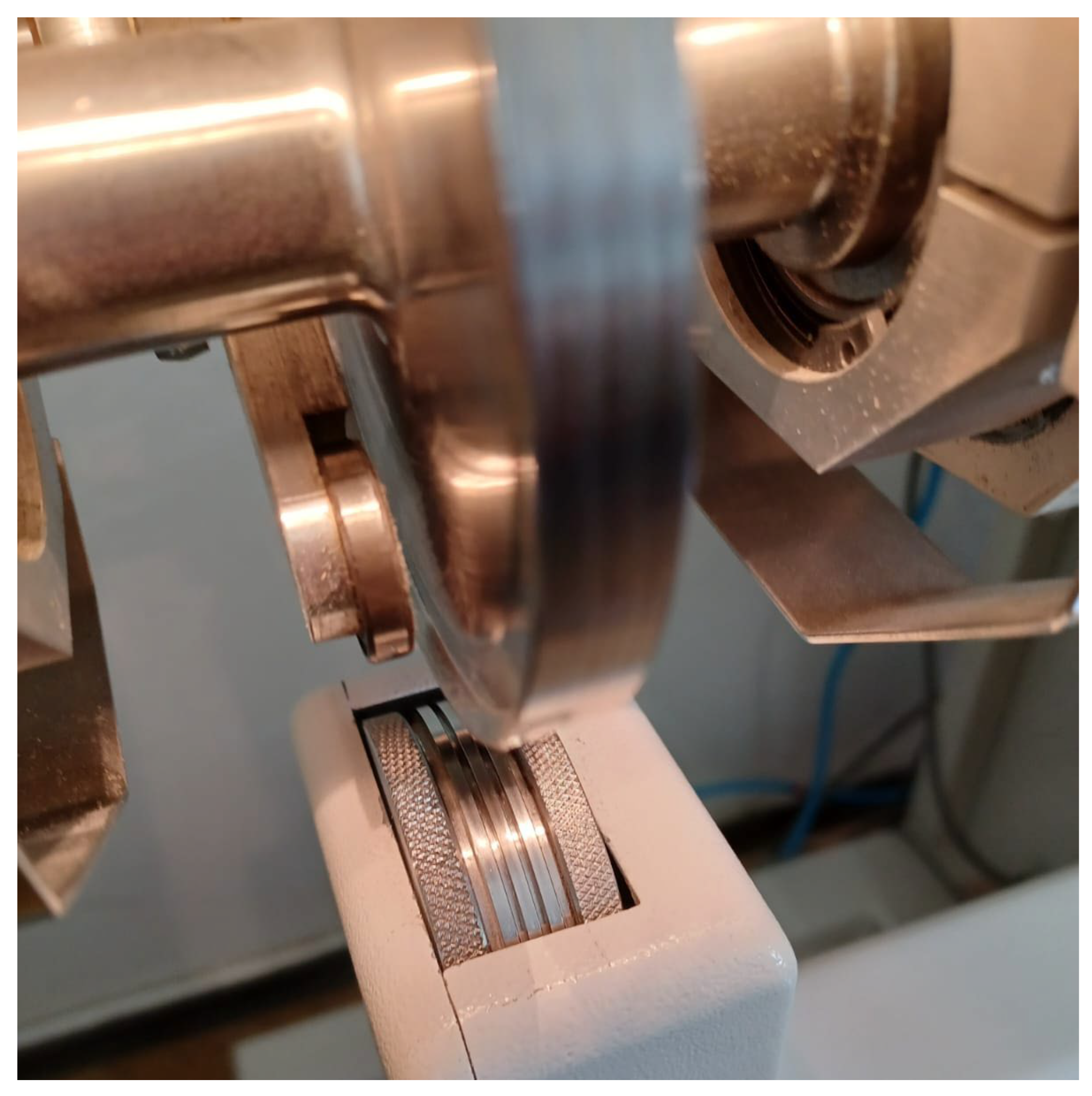
Figure 3. A rotary sonotrode,
Figure 4, with a welding speed of 0.6 to 13.6 m/min is a component of the ultrasonic machine. The ultrasonic generator has an adjustable power range of 200 to 400 W and runs at a frequency of 35 kHz. It sends the vibrations to a circular sonotrode with a 105 mm diameter and a 10 mm width.
Test of declared power of the ultrasonic generator and appropriate vibration amplitudes for this power were made using an Agilent Technologies InfiniVisions MSO-X 3024A oscilloscope [
18] and an MTI-2100 photonic sensor device [
19].
The photon sensor MTI-2100, a dual-channel optical measurement system that carries out non-contact measurements of displacements and vibrations, was utilized in this work. Because the MTI-2100 employs fiber optic technology, which implies that it does not subject the object being measured to stress and is not impacted by magnetic and electric forces, it was selected. At frequencies ranging from DC to more than 150 kHz, displacements in the 0.25 nm to 5.08 mm range can be measured. The maximum linear range in normal winning mode is in the order of 1 million (25 μm). The frequency response ranges from DC to 100 kHz. The typical normal sensitivity of probes is to the order of 0.025 μm/mV. Optically coupled neighboring pairs that send and receive fiber light are used by optical fiber displacement sensors. The interplay between the field of light transmission, or the original fibers, and the field of view of the receiving or detector fibers serves as the foundation for the research. At contact or zero spacing, the majority of the light from the original fibers is reflected back into the same fiber, sending just a little amount of light to the receiving fibers and resulting in a zero-power signal. With an output signal that has the following characteristics: −10 V DC to 10 V DC, 51 output impedance, stability at 12 h 1 °C, displacement of less than 1.0% of full scope, and stability at a temperature between 16 °C and 35° [
18], displacement tests are achievable.
The light source and light sensor are the two components of the displacement measurement system that is based on the measurement of light intensity (detector). The relocation results in a change in the optical power that reaches the detector in the most basic systems. Infrared LEDs and LASERs with greater ranges are typically used as visible light source. Such arrangements are advised for modest displacements because to their good linearity and steep upstream wing curve. To prevent cross-consolidation between the transmitting and receiving fibers, the fibers must be of the total internal reflection variety. The sensitivity depends on where both fiber types are placed in the beam. Even though they are affected by the shape of the beam-interrupting item, the cross-section of the detector, and the spatial distribution of the intensity of the light emitted by the source, the relationship between the light reaching the detector and the displacement is linear [
20]. In this way, the diagram dependence of the vibration amplitude of the rotary ultrasonic sonotrode on the declared power of the ultrasonic generator is defined. The amplitude values determined in this way are used to calculate the welding times according to the mathematical model.
In this paper, the quality of the welded joint was investigated in this paper by creating 42 groups of specimens welded at 7 welding speeds (i.e., joint times that depend on the circumferential speed of the sonotrode) and 6 declared electrical power of the ultrasonic generator. In this way, it is possible to determine the functional dependence of breaking forces of the ultrasonically welded joint on the declared power for each circumferential speed, i.e., welding time. From the diagram, the optimum welding parameters (generator power and circumferential speed of the ultrasonic rotary sonotrode) can be determined when the cutting force is maximum. The optimum parameter values can be useful for checking the values of the joint parameters according to the model and experiment.
A Sauter tensile tester, model HF 500 [
21], with a breaking strength of up to 500 N and a resolution of 0.1 N, was used to explore the impact of ultrasonic welding parameters on the breaking force of ultrasonic welds, which is dependent on the quantity of ultrasonic energy supplied.
Figure 5a shows the Sauter Electrical Horizontal Test Stand THM 500N500N with the tearing strength tester mounted on it [
22]. The test stand includes an adjustable elongation speed and automatic and manual control options. The strength tester’s test clamps, which are used to determine the test specimen’s width, have a 15 mm width. The test specimen was sandwiched between the strength tester’s movable clamp and the Test Stand’s fixed clamp, as shown in
Figure 5b.
The test material is a PVC foil with a thickness of 20 µm. The specific heat of the tested material c is 1 × 10³ J/mm3K, at the melting temperature T2 of 485 K and the ambient temperature T1 of 289 K. The specific melting heat L is 163 × 103 J/kg, and the specific density of the polymer material ρ is 1.4 × 10³ kg/m3.
PVC foil was used to create 15 × 50 mm2 measuring specimens. The aforementioned ultrasonic machine, which has an adjustable electrical power of the ultrasonic generator of 50 to 100%, or converted to a power of 200 to 400 W, was used to weld the test specimens. For this experiment, six power levels of 200 W, 244 W, 280 W, 320 W, 356 W, and 400 W were chosen. Seven welding speeds were also used, including 0.077 m/s, 0.097 m/s, 0.113 m/s, 0.125 m/s, 0.147 m/s, 0.167 m/s, and 0.227 m/s. To calculate the breaking force of the ultrasonic welds for each of the specified materials, 42 groups of 20 test specimens were created in line with the aforementioned information and evaluated on a strength tester.
The acoustic impedance of the sonotrode Z0 was 4.1 × 10⁷ kg/m2 s, the acoustic impedance of the material to be welded (acoustic impedance of the material), Z1, was 3.2 × 10⁶ kg/m2s. The acoustic damping factor of the material μA was 0.37 m−1.
The ultrasound intensity reflection coefficient between the material to be welded and the counter roller R and the ultrasound intensity reflection coefficient between the sonotrode and the material to be welded R1 amount to 0.73.
5. Discussion
The article lists 44 crucial process variables for welding polymer materials. There are three groups of parameters: parameters specific to the polymer material being ultrasonically welded (12 parameters), general acoustic and electroacoustic parameters (11 parameters), and technical parameters specific to the ultrasonic machine (21 parameters). Important acoustic parameters are also shown, including reflections and absorptions between the rotating counter roller, the polymer material, and the rotary ultrasonic sonotrode. This presentation served as the basis for the methodical creation of a mathematical model that may be utilized to determine several ultrasonic welding parameters. Additionally, in developing the model, consideration is given to how ultrasonic wave strength, propagation, reflections, and absorption relate to production engineering.
The approach described in this study uses a photon sensor to measure the vibration amplitudes of a rotary ultrasonic sonotrode while it is operating. The aforementioned measurement technique proved to be extremely accurate and well accepted during the experimental portion of this work. Using this technique, the ultrasonic rotary sonotrode vibration amplitudes can be modified on the ultrasound machine’s microcomputer screen for six different values of the ultrasonic generator’s stated power (200 W, 244 W, 280 W, 320 W, 356 W, and 400 W). As a result, a calibrated diagram was created, as seen in
Figure 6. As can be observed, the rotary ultrasonic rotary sonotrode’s vibration amplitude grows linearly with the increase in the declared power of the ultrasonic generator.
The breaking forces of ultrasonic welds were then examined in relation to the stipulated power and welding speed using 42 groups of test specimens. Seven different welding speeds (0.077 m/s, 0.097 m/s, 0.113 m/s, 0.125 m/s, 0.147 m/s, 0.167 m/s, 0.227 m/s) were employed in six groups of declared ultrasonic generator powers. The ultrasonic weld breaking force measuring equipment, shown in
Figure 3, was used to test the test specimens’ breaking strength. The dimensions of the test specimens were ascertained using its test clamps,
Figure 5b.
Table 1 shows the outcomes of calculating the breaking forces. The designations of visual inspections of the ultrasonic welds before,
Figure 7, and after tearing on the strength tester are included in addition to these data. Based on the collected data, functional relationships between the breaking forces of ultrasonic welds and the declared electric power of the ultrasonic generator and the speed at which the specimens were welded using the ultrasonic rotary sonotrode were formed (
Figure 8). The maximum breaking forces for various ultrasonic generator powers and welding speeds are displayed very clearly in
Figure 8. From the diagram, it can be deduced that an increase in the ultrasonic energy injected causes greater melting of the material and a higher breaking force of the weld. The breaking force of ultrasonic welds initially increases with an increase in the declared power of the ultrasonic generator. The breaking force can be increased until it reaches its limit, at which point the injected energy becomes excessive, causing excessive melting of the polymer material, harm to the weld, as well as a sharp decrease in breaking force. The plot in
Figure 8 shows that the maximum breaking force for the utilized polymer material ranges from 32 to 34 N for various declared powers of the ultrasonic generator and welding speed. The largest breaking forces are attained at the four observed maxima in
Figure 8, which correspond to the welding parameters’ ideal values. These maximum values served as a check on the mathematical model’s precision in accordance with expressions (1) to (32). The highest values were found for the welding speed of 0.077 m/s at the 200 W maximum power of the ultrasonic generator, 0.097 m/s at 250 W, 0.113 m/s at 268 W, and 0.125 m/s at 272 W.
It is necessary to calculate the amplitude of the oscillations of the rotary ultrasonic sonotrode using the calibrated diagram in
Figure 6 or a mathematical expression that links the amount of oscillation amplitude to the declared power of the ultrasonic generator A
0 = 0.484 + 0.3383 -Pd for each of the four determined declared powers of the ultrasonic generator at which the maximum breaking force occurs. The sonotrode’s real vibration amplitude can be found in values of 68.1, 85.1, 91.1, and 92.5 µm in
Table 2 for the powers at which the highest breaking force occurs (200 W, 250 W, 268 W, and 272 W). The mathematical model’s expression (28) can then be used to determine the ultrasonic sonotrode’s effective power, Pα (
Table 2). The calculated effective power of the sonotrode is significantly lower than the declared power when the declared power of the ultrasonic generator and the effective power of the ultrasonic rotary sonotrode are compared. This discrepancy results from the utilization coefficient of the ultrasonic circuit (eclectic losses of the piezoelectric plates and other mechanical losses).
Using the mathematical model and the declared welding power, the necessary welding periods were computed (tm and ts).
Table 2 shows the small differences that were calculated between the welding times actually accomplished and the required welding durations; these deviations are fairly acceptable for practical application. The heating of the weld’s starting point can be attributed to the mathematical model’s prediction of the delay time at which welding will occur tdy.
This can be used to demonstrate that, despite certain small simplifications, the mathematical model constructed is sound. Future scientific and applied research on ultrasonic welding of polymer materials can be well-founded on the mathematical model developed, in which 42 different factors are coupled by established mathematical interdependencies.


