Article

Six-Degrees-of-Freedom (6-DOF) Work Object Positional Calibration Using a Robot-Held Proximity Sensor

Division for Electricity, Uppsala University, Box 534, 751 21 Uppsala, Sweden
*
Author to whom correspondence should be addressed.
Machines 2013, 1(2), 63-80; https://doi.org/10.3390/machines1020063
Submission received: 30 May 2013 / Revised: 31 July 2013 / Accepted: 10 August 2013 / Published: 23 August 2013
(This article belongs to the Special Issue Advances and Challenges in Manufacturing Automation)

Abstract

:
Industrial automation has been recognized as a fundamental key to build and keep manufacturing industries in developed countries. In most automation tasks, knowing the exact position of the objects to handle is essential. This is often done using a positional calibration system, such as a camera-based vision system. In this article, an alternative six-degrees-of-freedom work object positional calibration method using a robot-held proximity sensor, is presented. A general trigonometry-based measurement and calculation procedure, which, step-by-step, adjusts a work object coordinate system to the actual work object position, is explained. For suitable robot tasks and work object geometries, the benefits with the presented method include its robustness, large work area and low investment cost. Some drawbacks can be longer cycle time and its limited capacity to handle unsorted and complicated objects. To validate the presented method, it was implemented in an experimental robot setup. In this robot cell, it was used to calibrate the position of a stator section work object, which is used in the Uppsala University Wave Energy Converter generator. Hereby the function of the positional calibration procedure was validated. Sufficient positioning accuracy for the stator winding task was achieved and theoretically validated based on the experiments.

1. Introduction

Manufacturing automation in general, and industrial robotics in particular, have recently been recognized as an essential key to keep manufacturing industries in countries with high personnel costs [1,2]. The world-wide number of installed industrial robots has been rapidly increased during the past years and this growth is forecasted to continue within the following years (IFR Statistical Department. Executive Summary: World Robotics 2012 Industrial Robots. Retrieved 2013-05-30: http://www.worldrobotics.org/uploads/media/Executive_Summary_WR_2012.pdf). With robots being used for a wider spectrum of tasks and by a wider spectrum of users, the need for simple, cheap and robust robot equipment and support systems is also increasing.
Positional calibration of work objects, i.e., finding the exact position of the object to handle, is a common problem in robot automation. There are several techniques that can be used for such measurements. Two examples of advanced commercial systems are camera-based vision systems and force feedback systems, but other sensors such as probes, laser sensors or proximity sensors can also be used [3,4,5,6,7,8]. Vision-based systems are also used for similar applications with humanoid and mobile robots [9,10]. For a robot to be able to handle an object with high precision, its absolute positioning accuracy is critical. In general, industrial robots are known for high positioning repeatability, but perform worse in absolute positioning. The absolute positioning accuracy can however be improved substantially through absolute calibration of the robot or with positioning feedback and compensation systems [11,12].
This paper presents a six-degrees-of-freedom (6-DOF) positional calibration method, using a robot-held proximity sensor. A general trigonometry-based measurement and calculation procedure has been developed for the positional calibration. This procedure is used to step-by-step find the position of different work objects. Compared to many existing commercial positional calibration systems, the presented method is a simple, inexpensive and robust solution. It might be beneficial for use in longer cycle-time tasks on rather large, medium complex, well defined work objects where a rough estimation of the present position is known. Another example could be in applications with special requirements, such as varying surrounding light and when it is not allowed to touch the surface of the work object. The presented calibration method is evaluated through experiments. In these experiments, the 6-DOF position and rotation of a medium complex geometry stator section prototype, used in a Wave Energy Converter (WEC) generator developed at Uppsala University (UU), is measured.

The UU WEC Stator Section Example

In the quest for more renewable energy sources in our global energy system, electric generators and motors are two examples of large machines that are likely to grow in numbers in the near future. Building these electric machines includes many repetitive assembly operations, such as stator stacking, stator winding and rotor assembly. Some of these operations may be suitable for industrial robot automation. Examples of such electric machine assembly automation can be found in [13,14,15].
An example of such new large generator design is the UU WEC generator [16,17]. This generator is linear, direct-driven, has a permanently magnetized translator and a cable wound stator, see Figure 1. Figure 2 shows the stator design and defines some key parts of the stator. A robotized automation solution for cable winding of the UU WEC stator is currently being developed at UU [18]. This robot cell uses four industrial robots, all equipped with cable feeder tools which has been designed and constructed for the specific task, see Figure 3. By cooperating, it is estimated that the robots can complete the cable winding of a UU WEC stator section in 215 minutes. The corresponding cycle time for manual cable winding with four personnel is about 20 hours.
Figure 1. (a) A simplified model of the Uppsala University (UU) Wave Energy Converter (WEC) generator design. (b) A cable wound UU WEC stator section mounted inside a UU WEC generator housing. One UU WEC stator is built up from four stator sections, together forming an octagonal shape.
Machines 01 00063 g001
Figure 2. Definition of some key parts of the UU WEC stator section design.
Machines 01 00063 g002
Figure 3. A simulation snapshot of the suggested robotized cable winding cell, created in ABB RobotStudio.
Machines 01 00063 g003
The proposed cable winding automation starts as a new stator section is transported into the winding cell and positioned between the industrial robots. For the winding automation to function, it is necessary that the robots know the exact position of the stator section. In particular, the exact position of the stator section slot holes must be known. The positioning must have the same high precision every time a new stator section is positioned in the robot cell. Due to inevitable tolerances in the initial positioning of the stator section and because the geometry of the stator section itself can vary somewhat, a suitable positioning calibration method must be found and used to calibrate the robot movements to the actual work object position.

2. Experimental Setup and Method

The developed positional calibration method was validated in an experimental setup for robotized cable winding, see Figure 4. In this robot cell, an ABB IRB4400/60 kg M2000 S4C+ robot was equipped with a cable feeder tool. On top of the robot tool, an 18 mm diameter cylindrical, shielded proximity sensor, with 8 mm sensing distance, was mounted, see Figure 5a. This sensor was used for the work object positional calibration measurements. To facilitate positioning of the robot while measuring the work object position, a Tool Centre Point Coordinate System (TCPCS) was created at the sensing distance in front of the proximity sensor. For positioning the feeder against the stator section during robotized cable winding, two other TCPCSs were created on the cable guiding ends of the cable feeder tool. All TCPCSs are shown in Figure 5b.
The work object in the robot cell was a UU WEC stator section prototype. While a full size UU WEC stator section is 2 m long, the stator section prototype was built up from left over stator sheets which were cut into 0.5 m long parts. Hence, the short side of the stator section was quite rough and some slot holes had to be used for bayonet pins and tightening bolts. In robotized winding of a full length UU WEC stator section, however, with the robots working in pairs, each robot must reach over about 1 m length of the stator side surface.
Figure 4. The cable winding experimental robot cell setup. Two ABB IRB4400/60 kg S4C+ M2000 robots, equipped with cable feeder tools, are performing cable winding through a 0.5 m long UU WEC stator section prototype.
Machines 01 00063 g004
Figure 5. (a) A proximity sensor was mounted on top of a cable feeder robot tool and used to take positional measurements on the stator section. (b) The three Tool Centre Point Coordinate Systems (TCPCSs) created at the cable feeder tool and used for positioning the robot. One TCPCS is placed at the sensing distance from the detecting surface of the proximity sensor and two are placed on the ends of the cable guiding tubes.
Machines 01 00063 g005
In the positional calibration procedure, the robot used the proximity sensor to measure the stator section position in some predefined points on the stator section surface, see Figure 6. By combining a number of such measurements, 6-DOF positional calibration was achieved. The positional calibration was repeated several times for the same stator section prototype position and the results were compared to each other. By assuming that the mean value of these measurements was adjusted to the actual stator section geometry, the positioning accuracy for each measurement was calculated. These measurements were then repeated 20 times for 20 different stator section positions. The maximum displacement of the stator section between the measurements was more than 20 mm and more than 3 degrees. These measurements were then used to evaluate the positional calibration method by calculating the standard deviation of the positional calibration results. Since the positional calibration includes the rotation of the stator section, the experimental results must also take into account that the positioning error depends on against which slot hole the robot is positioned. This error is likely to increase with the distance to the WOCS origin.
Figure 6. (a) The proximity sensor mounted on top of the cable feeder tool is used to measure the position of the stator section surface in one point. (b) A close-up of the robot-held proximity sensor while used to measure the position of the stator section over a stator tooth.
Machines 01 00063 g006

3. Positional Calibration Procedure

3.1. General Positional Calibration Calculations

From the positional measurements with the proximity sensor, the work object position in the Robot Base Coordinate System (RBCS) can be calculated. A Work Object Coordinate System (WOCS) is then created in the RBCS and adjusted to the work object geometry and position, e.g., positioned at a corner and aligned with one or more edges of the work object. Knowing the work object geometry and assuming high geometrical accuracy, the WOCS can thereby be used to create different robot targets on and thereby position the robot against the work object surface. Working in the WOCS instead of the RBCS will thus facilitate programming of the robot considerably. It also improves the flexibility of the robot programming, as all programmed robot targets are related to the WOCS, which can easily be adjusted in both position and rotation if needed.
The general algebraic solution of the work object positional calibration method is based on a series of trigonometric calculations, which in turn are based on the measured points on the work object. These calculations start from an assumption of the work object position and are then repeated until a satisfying positional calibration is achieved. 
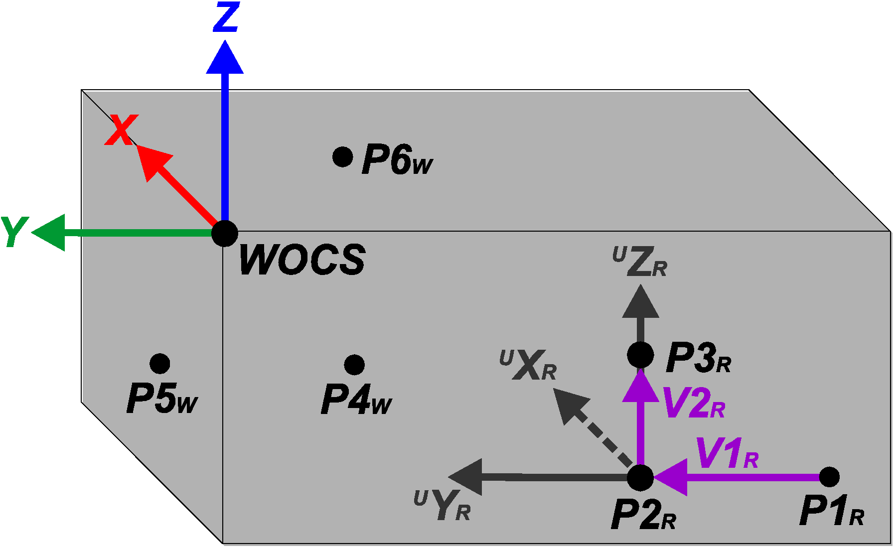
Figure 7 shows the positions of the measured points, the vectors used in the positional calibration calculations and the calibrated WOCS on a general work object geometry.
Figure 7. A general work object, showing the positions of measurements P1-P6, the vectors used in the positional calibration calculations and the position and rotation of the calibrated Work Object Coordinate System (WOCS).
Machines 01 00063 g007
Starting with the three points P1R, P2R and P3R, two vectors in the yz-plane of the sought WOCS, V1R and V2R, are calculated in the RBCS. V1R is calculated from P1R to P2R using that
Machines 01 00063 i001
and V2R is calculated from P2R to P3R using that
Machines 01 00063 i002
A normal vector to the yz-plane, XR, directed in the positive x-axis direction of the sought WOCS, is then calculated in the RBCS as the cross product between V1R and V2R, knowing that
Machines 01 00063 i003
Assuming that two of the points on the work object side, P1R and P2R, are placed parallel to the y-axis direction of the sought WOCS, V1R can be used as vector YR, which is thus directed in the positive y-axis direction of the sought WOCS. A third vector, ZR, which is perpendicular to XR and YR and directed in the positive z-axis direction of the sought WOCS, can now be calculated as the cross product between XR and YR, knowing that
Machines 01 00063 i004
These three vectors, XR, YR and ZR, describe the orientation of the work object relative to the RBCS. Hence, the WOCS orientation can now be aligned with the work object orientation. This is done by first transforming XR, YR and ZR to unit vectors UXR, UYR and UZR. Then the rotational matrix from RBCS to WOCS, RRW, is calculated from the unit vectors of the RBCS and the unit vectors from the WOCS, both described in the RBCS. The unit vectors of the RBCS, UXR0, UYR0 and UZR0, are defined as
Machines 01 00063 i005
The elements in RRW can now be calculated using the dot product, knowing that
Machines 01 00063 i006
Now the orientation of the WOCS relative to the RBCS can be described in Tait-Bryan z-y’-x’’ angles, α, β and γ, which can be used in the robot programming, knowing that
Machines 01 00063 i007
Machines 01 00063 i008
Machines 01 00063 i009
Finally three new points, P4W, P5W and P6W, measured in the orientation-adjusted WOCS and placed on three sides of the work object, are used. Thus, the WOCS origin can be adjusted and expressed in the earlier preliminary WOCS. This is done by using the x-coordinate of P4W, the y-coordinate of P5W and the z-coordinate of P6W, all expressed in the assumed WOCS. The WOCS origin is then expressed in the RBCS, by using the rotational matrix from RBCS to WOCS, RRW, and knowing that
Machines 01 00063 i010

3.2. The UU WEC Stator Section Example

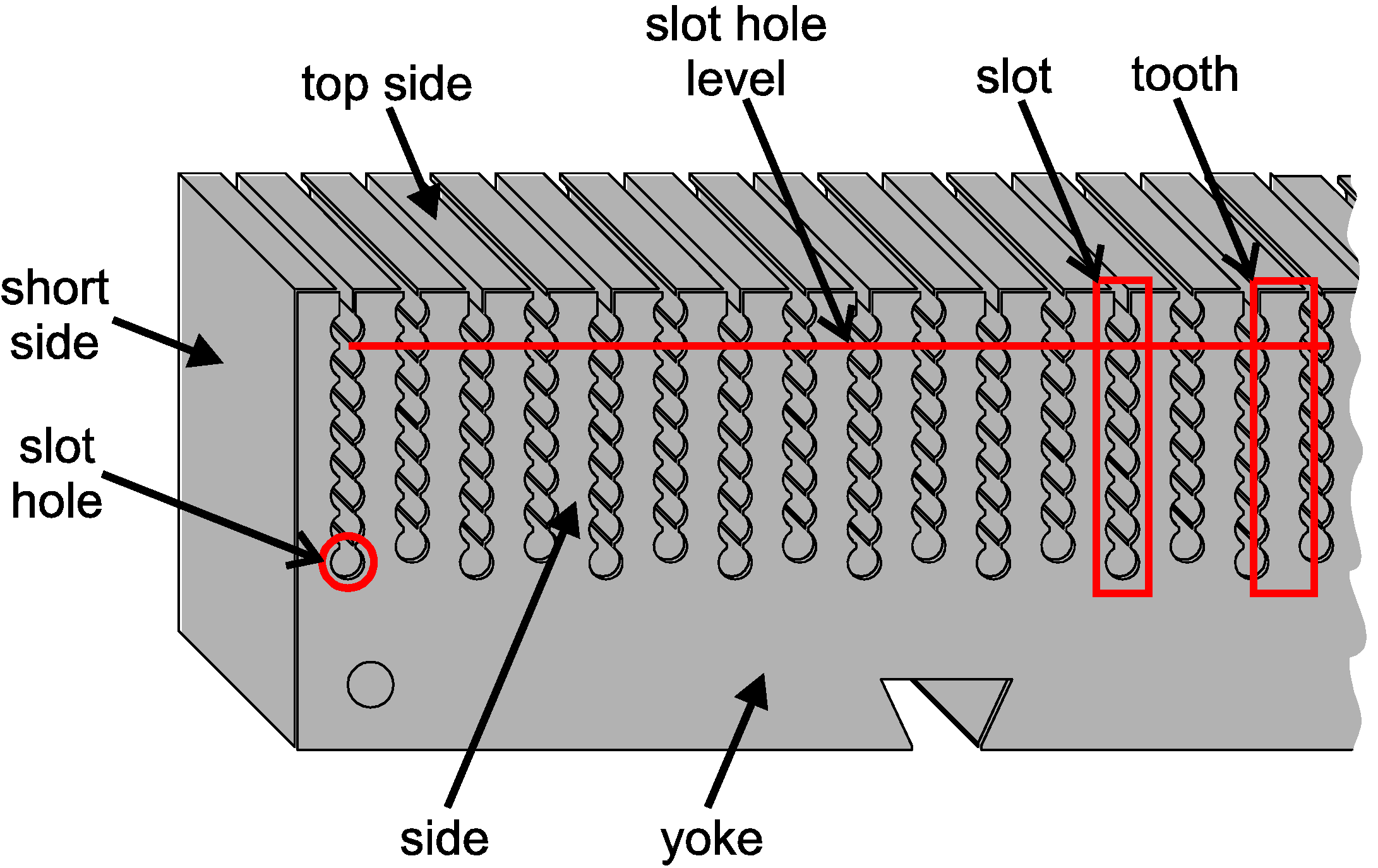
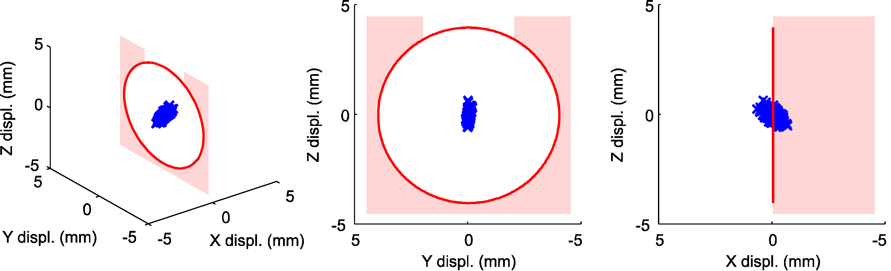
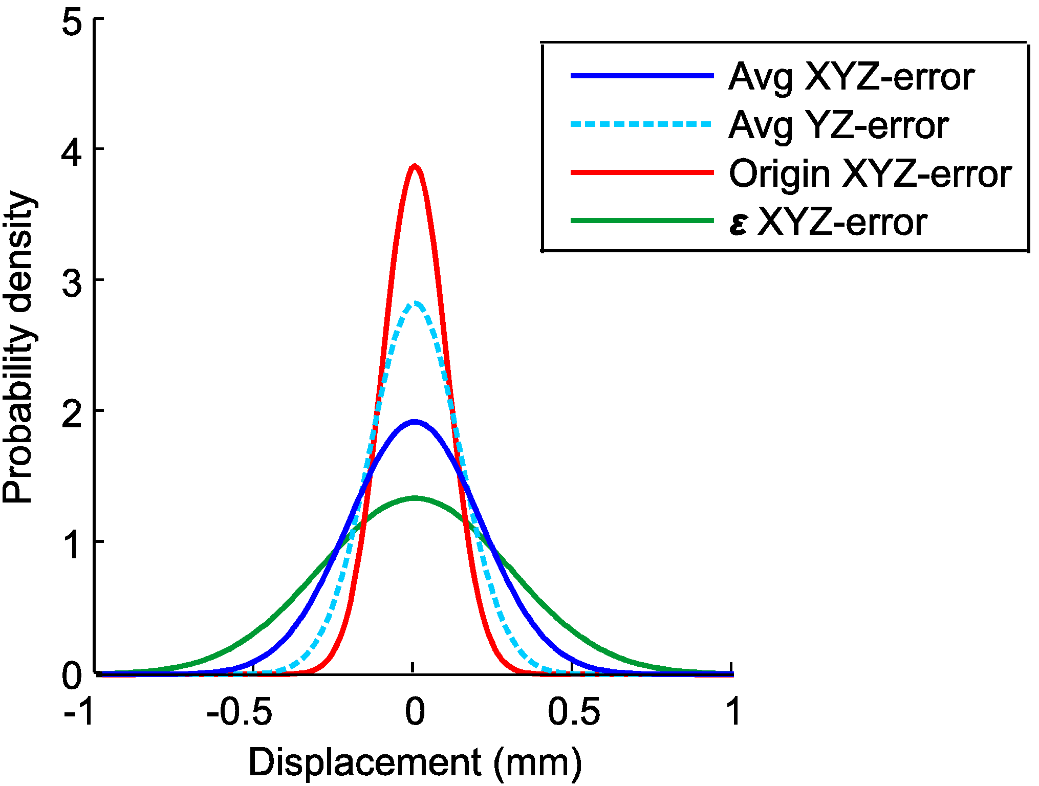
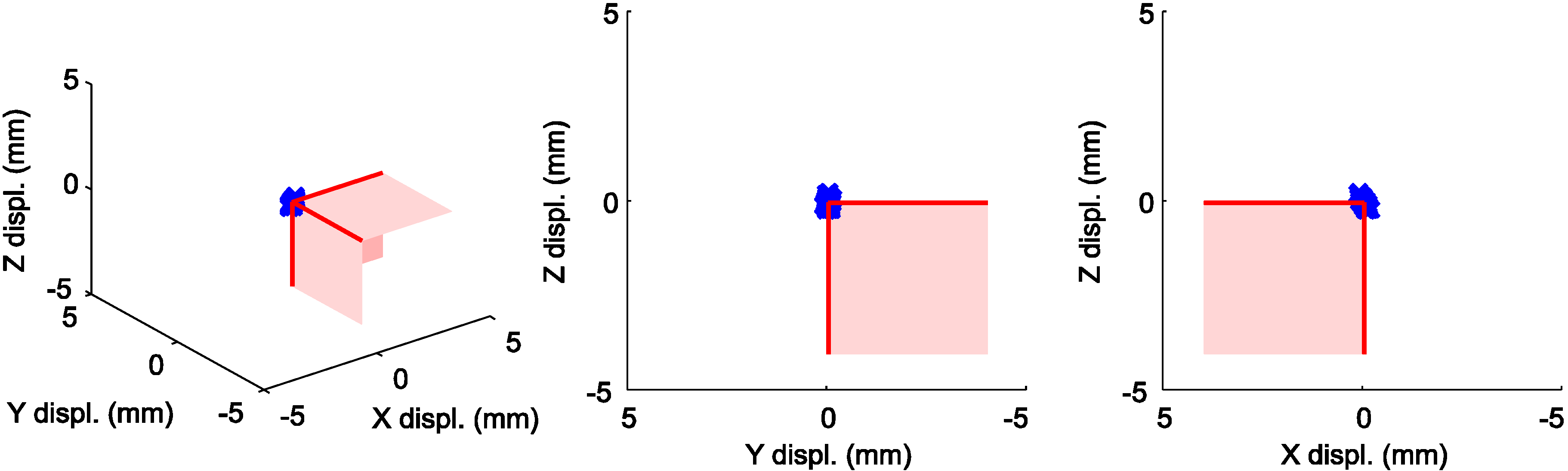
In order for the cable winding automation to run smoothly, the maximum absolute positioning error at a stator slot hole should be about 1.0 mm with a 99.99% confidence level. This would result in about 50 positioning errors above 1.0 mm during one year of continuous production in one robot cell. Furthermore, the positional calibration method must be robust in terms of reasonable changes in the surrounding environment. It would also be favorably if the calibration method is fairly inexpensive and simple enough to be used with older robot models.
If the WOCS is positioned at a corner of the stator section and aligned with the stator section geometry, the absolute positioning error of the cable feeder tool after the positional calibration, relative to the stator section, will depend also on the rotational accuracy of the WOCS. Hence the absolute positioning error will increase with the distance to the WOCS origin. During the cable winding task, the absolute positioning error will therefore be largest at the slot hole being furthest away from the WOCS origin, ε, see Figure 8a. Another reason for limiting the orientation error of the calibration is the importance of feeding the cable straight into the slot holes. In order for the cable winding automation to run smoothly, the maximum rotational error, around the WOCS x-, y- and z-axes respectively, at a stator slot hole should be about 1.0° with a 99.99% confidence level.
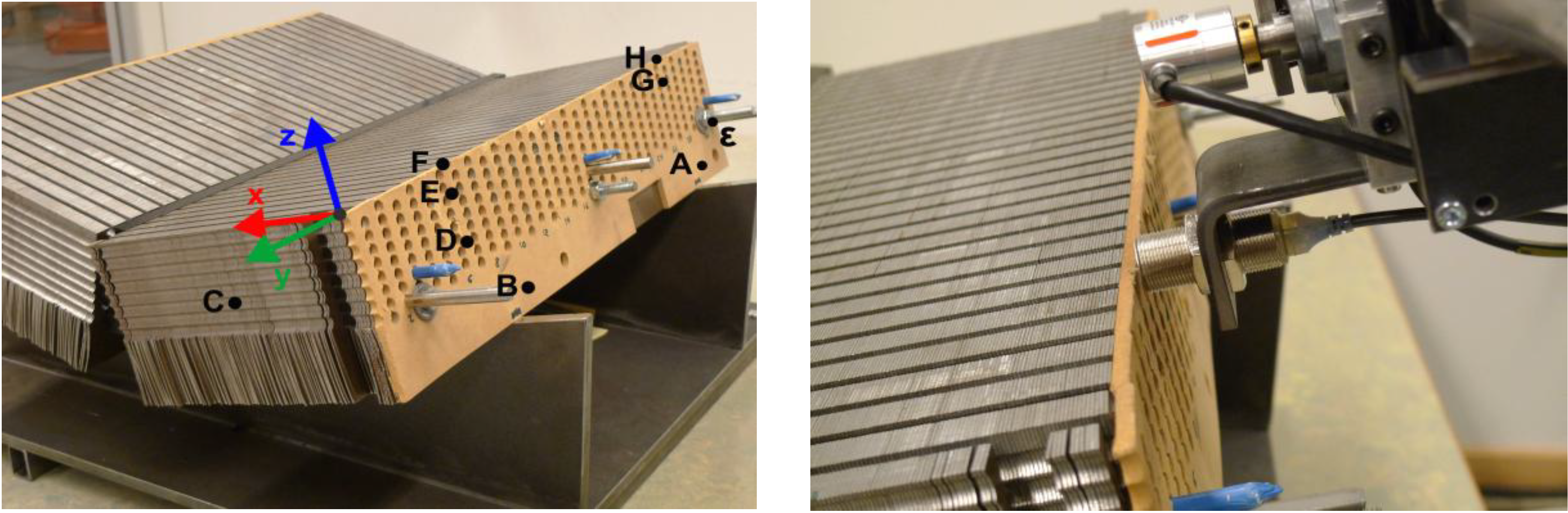
Figure 8. (a) The position of the measured points AH on the stator section surface, the position of ε and the position and rotation of the calibrated WOCS. The tightening bolts, here preliminary placed in slots number 3, 15 and 31 together with bayonet pins and short cable parts, deforms the stator section somewhat in the x-direction of the WOCS. (b) The proximity sensor while positioned to search for the edge between the stator section side and top side by moving upwards over a stator tooth while being within the sensing distance to the stator section side.
Machines 01 00063 g008
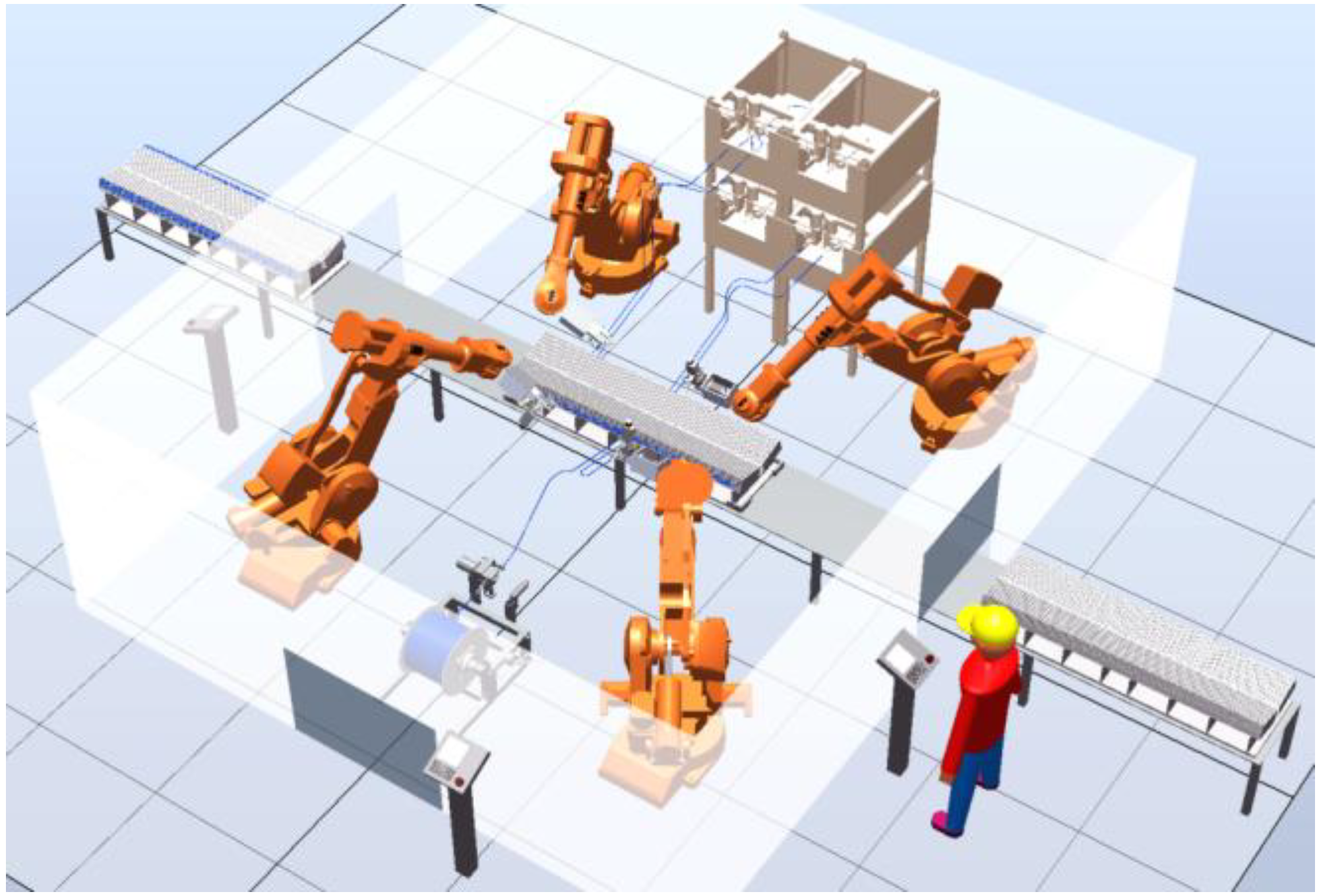
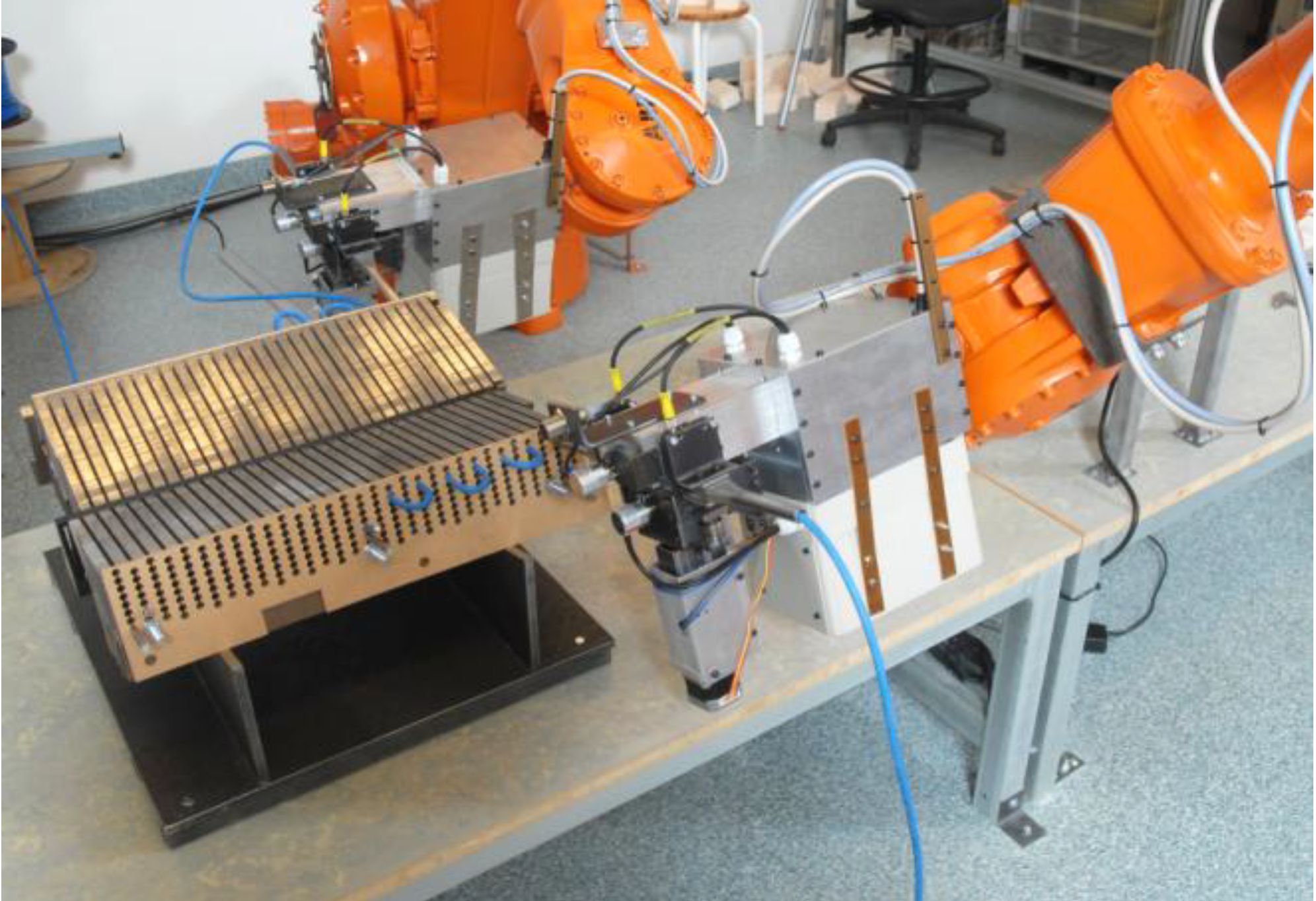
In the cable winding robot cell, a stator section is automatically transported and positioned between the robots. A high precision fixture design is used to support the stator section, which is stacked from about 500 high precision stator sheets and held together by tightening bolts. Hence, the geometrical accuracy between the stator section slot holes is high while the thickness of the stacked stator section can vary somewhat. The position of the stator section in the robot cell can be assumed to vary only a few millimeters and less than one degree. However, when measuring the stator section geometry even a positioning deviation of less than a few millimeters might result in a measurement being taken with the proximity sensor positioned over a stator section slot hole. Since less ferromagnetic material is then available, the measurement might be incorrect relative to measurements taken over a solid part of the stator section.
Another problem is that the stator section side becomes a bit deformed by the tightening bolts which are used to hold together the stator section plates, see Figure 8a. This deformation arises mainly in the x-direction of the WOCS and can be neglected in the y- and z-directions.
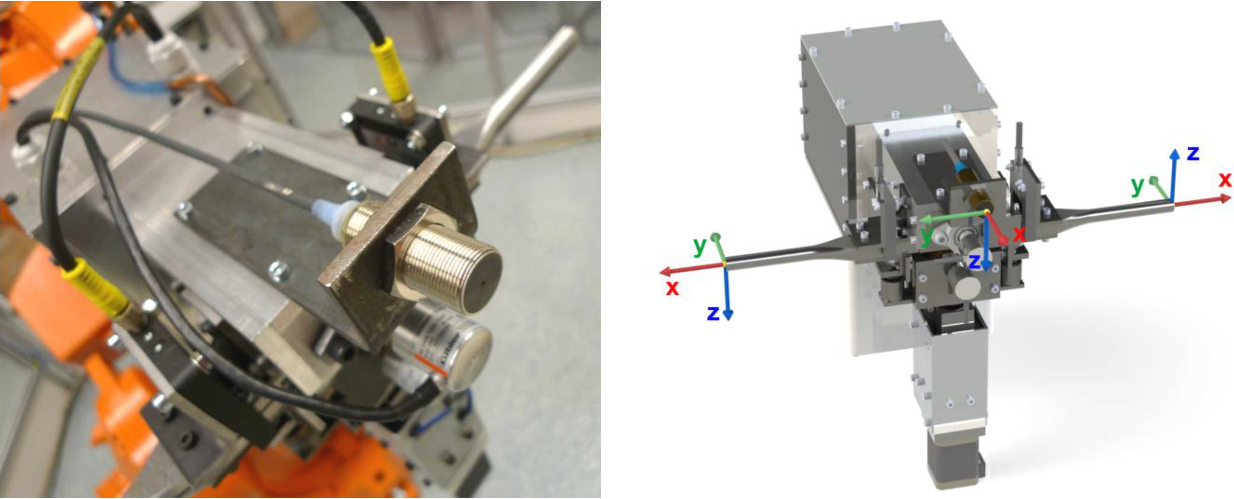
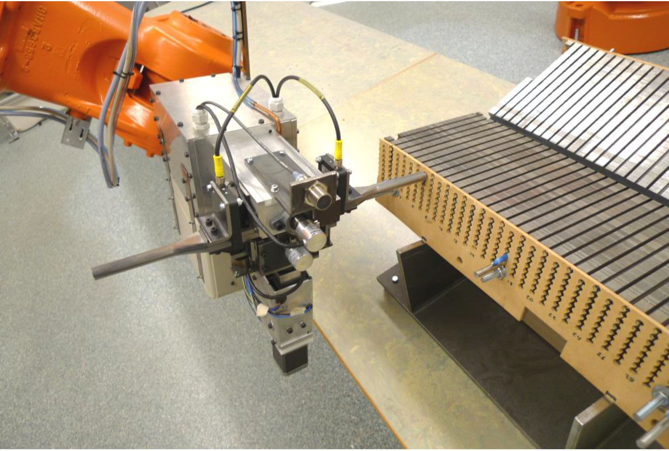
Due to the desired robot model and placement relative to the stator section, to the cable feeder tool design and to the stator section geometry, the robot reach for taking measurements with the proximity sensor was somewhat limited. As a consequence, measurements could not be taken on the top side of the stator section. In order to get the required measurements, the proximity sensor was instead moved upwards over the stator section side, within the sensing distance to the stator section, searching for the edge between the stator section side and the top side, see Figure 8b.
In the UU WEC stator section positional calibration procedure, in total eight points on the stator section geometry are measured, see Figure 8a. The positional calibration starts from an approximation of the stator section position in a preliminary WOCS. This approximation is first used to measure points A and B. In order to avoid that the measurements are disturbed by, e.g., slot holes on the stator section side, the measurements are taken on the yoke of the stator section. Knowing that the stator section is placed on a high precision fixture and table, measurements A and B are assumed to be placed parallel to the y-axis direction of the sought WOCS. Hence measurement A can be used as P1R and measurement B can be used as P2R. P3R is calculated as a point 50 mm above B at the stator section side surface by first calculating the WOCS rotation around the z-axis, α1, from A and B and assuming the inclination of the stator side relative to the RBCS, β1, to be 15°. We get
Machines 01 00063 i011
Machines 01 00063 i012
As a result, a preliminary calculation of the WOCS rotation can be made using Equations (1)–(9) a (11) and (12) and B can be used as P4W with Equation 10 to preliminary adjust the x-axis origin of the WOCS.
Next, measurement C is performed in the adjusted WOCS on the short side of the stator section and used as P5W with Equation (10) to preliminary adjust the y-axis origin of the WOCS.
Assuming that the WOCS rotation around the x-axis differs very little from the start approximation, measurements D and E can now be taken with high accuracy over a stator section tooth and used as P3R and P2R. By combining measurements A, B, D and E, the WOCS yz-plane can be adjusted to the side of the stator section. The previously calculated V1R is then used with the new P2R and P3R and Equations (2)–(9) to adjust the rotation of the WOCS, which is thereby adjusted around the WOCS y- and z-axes. Since measurement E is taken at a better defined position on the stator section side, this measurement can be used as P5W with Equation (10) to improve the position of the WOCS x-axis origin.
Next, point F is measured by moving the proximity sensor upwards, in the positive z-axis direction of the WOCS, over a stator section tooth within the sensing distance to the stator section side, beginning a few millimeters offset in the positive WOCS x-axis from point E. The edge is found as the end of the side surface is reached and the sensor stops detecting. Next, point G is measured and used as starting point in measuring point H, using the same procedure as for point F. The final WOCS rotation is now calculated using H as P1R, F as P2R and D as P3R with Equations (1)–(9), by inverting the direction of V2R. Finally, measurement H is used as P6Wz and measurements C and D are retaken and used as P5Wy and P4Wx with Equation (10) to decide the final position of the WOCS origin.
As the WOCS adjustment to the stator section geometry is finished, the varying x-direction offset of the stator section side surface is measured and calculated. This is done by using the x-component of the offset measurement, PXWx, expressed in the WOCS, and repeating the measurement for every second stator tooth at two different slot hole levels on the stator section side. By combining these measurement results, the x-offset for each slot hole position can be estimated. These x-offset results are saved in a m × n-matrix, MXW, where the rows represent the slot hole layers and the columns represent the slot number. Thus, with i and j representing the slot hole layer and the slot number for an individual slot hole and k and l representing the slot hole level and the slot tooth number for an individual x-offset measurement, we get
Machines 01 00063 i013
where
Machines 01 00063 i014
Using the adjusted WOCS and the x-offset matrix, all slot hole positions can easily be calculated from knowing the stator section dimensions. To facilitate positioning during robotized cable winding, a new function is created in the robot programming. If given the desired slot number and slot hole layer, this function returns a robot target fitted at to the specified slot hole. The rotation of the robot target is aligned with the WOCS, while the position of the robot target is calculated as a geometrical offset in the y- and z-axes directions, and adjusted by the x-offset matrix in the x-axis direction, relative to the WOCS origin. If desired the function can create a robot target with a user defined distance and rotation relative to a slot hole. Hence, by using the presented positional calibration method and the described programming function, creating robot targets for positioning the cable feeder tool against different slot holes is very straightforward.

4. Experimental Results

The positional calibration method, including the algebraic solution and robot programming described in Section 3, was implemented in the experimental robot cell setup described in Section 2. Robotized cable winding experiments, using the stator section positional calibration method, were performed successfully in this setup. Hereby the function of the presented positional calibration method was validated, as it provided sufficient positioning accuracy for the robot relative to the stator section slot holes, see Figure 9.
Figure 9. The robot-held cable feeder tool is positioned with one end of the cable guiding tube against a slot hole on the stator section prototype side, using the calibrated WOCS.
Machines 01 00063 g009
Figure 10 shows the positions of the calibrated WOCS origins for the 400 stator section positional calibrations, relative to the mean value of these measurements. In Figure 11, the corresponding calculated positions of ε in the calibrated WOCS are shown. The distance from ε to the WOCS origin is set to 1,000 mm in the negative y-direction and 100 mm in the negative z-direction.
Figure 10. The calibrated positions of the WOCS origins are marked with blue crosses, while the assumed correct position of the UU WEC stator section corner is shown in red. The figure is based on 400 measurements.
Machines 01 00063 g010
It can be seen in Figure 10 and Figure 11 that a large contribution to the absolute positioning error at ε comes from rotational errors in the WOCS. It can also be observed that the absolute error in the x-direction of the WOCS makes a significant contribution to the total xyz-space error. However, since additional x-offset values are measured and because absolute positioning errors in this direction are less important for the cable winding, the x-direction offset in these results can be neglected. The important positioning error is therefore in the yz-plane of the WOCS.
Figure 11. The calculated positions of ε are marked with blue crosses, while the correct UU WEC stator section slot position is shown in red. The figure is based on 400 measurements.
Machines 01 00063 g011
From the 400 calibrations, normal distributions of the positioning errors were calculated. The normal distributions were divided into positioning errors in the yz-plane and in the xyz-space at the WOCS origin, into positioning errors in the yz-plane and in the xyz-space at ε, into positioning errors of the WOCS origin in the x-, y- and z-axis and into rotational errors of the WOCS around the x-, y- and z-axis. By using each measured WOCS to calculate the position of all 500 slot holes on one stator section, 200,000 different robot targets were created for the 400 WOCS calibrations. Comparing these robot target positions to the assumed correct positions gives a normal distribution of the absolute positioning error for all stator section slot holes on the stator section side.
In calculating normal distributions in the yz-plane and in the xyz-space, the displacement is defined as positive if the displacement is positive in the x-axis of the WOCS. The resulting normal distributions and confidence intervals for different confidence levels are shown in Figure 12 and Table 1.
The cycle time for the full stator section calibration was about 100 s for calibrating the WOCS and 150 s for measuring the x-offset matrix over a full size stator side.
Figure 12. Normal distributions of the calculated absolute positioning errors from the UU WEC stator section positional calibration experiments, based on 400 measurements.
Machines 01 00063 g012
Table 1. Confidence intervals for the calculated absolute positioning errors from the UU WEC stator section positional calibration experiments, based on 400 measurements. The frequency number represents approximately how often an error outside the confidence interval will occur in one cable winding robot cell in full operation during one year.
Normal distributionConfidence Level [%]Frequency [times/year]Confidence Interval
WOCS origin x-axis95.522 500±0.10 mm
WOCS origin y-axis95.522 500±0.08 mm
WOCS origin z-axis95.522 500±0.16 mm
WOCS rotation x-axis95.522 500±0.0002°
WOCS rotation y-axis95.522 500±0.0018°
WOCS rotation z-axis95.522 500±0.0003°
WOCS rotation x-axis99.9950±0.0004°
WOCS rotation y-axis99.9950±0.0035°
WOCS rotation z-axis99.9950±0.0006°
WOCS yz-plane origin95.545±0.18 mm
WOCS yz-plane origin9910±0.23 mm
WOCS yz-plane origin99.91±0.30 mm
WOCS yz-plane at ε95.545±0.40 mm
WOCS yz-plane at ε9910±0.51 mm
WOCS yz-plane at ε99.91±0.66 mm
WOCS yz-plane stator side95.522 500±0.28 mm
WOCS yz-plane stator side99.9950±0.55 mm
WOCS yz-plane stator side99.9995±0.62 mm
WOCS yz-plane stator side99.99990.5±0.69 mm

5. Discussion

The function of the presented 6-DOF positional calibration method, including the trigonometry-based measurement and calculation procedure, was validated through experiments with a UU WEC stator section prototype. In theses experiments, the examined work object was shaped like a large, rectangular parallelepiped and its front side was penetrated by a pattern of stator slots. The same calibration method can be easily be implemented also for other work object geometries. However, for the calibration method to be easily implemented, the work object should be well defined, have at least one plane surface and its position should be roughly known from the beginning. It must also be possible for the robot to reach around the work object while taking measurements. By replacing the proximity sensor with, e.g., a capacitive sensor or a miniature snap-action switch, non-ferromagnetic materials can be detected. As indicated by the UU WEC stator section example, work objects with complicated geometries might require step-by-step positional calibration through repeated measurements. With a simpler geometry on the other hand, the positional calibration procedure can be simplified and a lower cycle time can thus be achieved.
For tasks fulfilling the demands described above, there are some possible benefits with the presented positional calibration method. One benefit is the robustness of the method and equipment, such as being insensitive to changes in the surrounding light. Another benefit is the large possible work area and ability to take measurements on different sides of the work object provided by the robot itself. Also, with the proximity sensor placed on the robot tool, positioning of the robot will be similar during the work object positional calibration and when later working with the work object. Hence the positional calibration will to some extent include compensation for the robot-specific absolute positioning error against the stator section. This is especially true if the robot moves in a restricted area with relatively small joint axis movements and given that the robot joint axis rotations are similar during the positional calibration and the following robot task. Further, the use of inexpensive and simple equipment and the possibility to include the calibration procedure directly into the robot programming independent of robot model makes the method inexpensive, simple and easy to implement.
On the other hand, depending on the application there are some possible drawbacks with the presented method compared to, e.g., commercial vision systems. An important drawback is the methods limited capability to detect and identify different objects, especially if they are unsorted, due to the need to have a good start estimation for the search procedure and the need for the robot to reach around the work object while taking measurements. Another important drawback is that the method might be very hard and time consuming or even impossible to implement for complicated geometries. The positioning calibration cycle time can also be quite long, especially for complicated work objects. Since the robot holds the proximity sensor, the calibration can not be done simultaneously with other robot tasks and thus the calibration cycle time will be more likely to directly add to the total product cycle time. Finally, by using a robot-held sensor, the calibration accuracy will depend also on the robot absolute positioning accuracy and on the proximity sensor detecting distance accuracy. This can be a problem both when the robot later works with the work object and if the robot is supposed to share the calibration results with other equipment.

The UU WEC Stator Section Example

Positional calibration of the UU WEC stator section requires a robust method with high accuracy results over the full stator surface, which was achieved with the developed method. With a total stator section winding cycle time of 215 min, the resulting positional calibration cycle time, 4 min per stator section, will only make a minor contribution to the total product cycle time. Hence robustness and accuracy are prioritized over a very low cycle time.
The experiments with the stator section resulted in a ±0.55 mm confidence interval for positioning over the full 1,000 × 100 mm stator section side relative to the calibrated stator section position, with a 99.99% confidence level. However, the robots used in the stator section positional calibration experiments were not absolute calibrated, which may also have influenced the results. The specified linear path accuracy performance of the used robot model was 0.8–1.3 mm, specified for the full reach of an un-used robot. As the robot is positioned against the stator section side in the cable winding task, only small rotations of the robots joint axes 1–5 are required since the work area is restricted. If the robot absolute accuracy performance thereby is assumed to be included in the positional calibration result, this positioning error can be neglected in the total positioning error for the winding task. Further, the robot positioning repeatability was not considered in the experiments. This did probably influence the measurements and this must thus be included in the total positioning error. The specified linear path repeatability performance of the robot used in the experiments was 0.25–0.4 mm, for the full reach of an un-used robot. By adding this repeatability accuracy to the total positioning error for the winding task, the resulting accuracy will still be within the specified requirement of ±1.0 mm with a 99.99% confidence level.
The experimental results regarding the rotational accuracy of the calibrated WOCS relative to the stator section geometry validated that the presented method well fulfilled the specified requirement of maximum ±1.0° rotational error for the x-, y- and z-axes respectively with a 99.99% confidence level.
Two specific problems with positional calibration of the UU WEC stator section were the uneven short side of the stator section, which probably effected measurement C, and the limited robot reach, which made it impossible to take measurements on the stator section top side. The results might also have been improved by using a more precise and smaller diameter proximity sensor. It should as well be noted that calibration of the TCPCSs on the robot tool adds another accuracy error to the calibration method. Thus this tool calibration must be performed with high accuracy.
Manual winding experience has shown that there is a risk that the stator section teeth are bent somewhat outwards as a cable is fed through. This did not occur during the initial robot winding experiments. However if such deformation cannot be completely avoided, this geometrical change must be identified during the actual winding. It would, e.g., be possible to complete the described positional calibration by using, e.g., bayonet pins in unwound stator slot holes with a force feedback system during the winding. Such a system would on the other hand be rather expensive.
To perform a compete analysis of using the implementation of the presented positional calibration method for calibrating the UU WEC stator section position, further experiments, preferably on several different full length stator sections, are needed. Using absolute calibrated robots and, e.g., a laser tracking system to determine the actual robot positioning accuracy after the calibration would also improve the analysis. Such equipment was however not available for this work.

6. Conclusions

A trigonometry-based measurement and calculation procedure for 6-DOF work object positional calibration using an industrial robot equipped with a proximity sensor has been presented. The method require a well defined work object with at least one plane surface, a rough start estimation of the work object position and orientation and space around the work object for the robot to be able to take measurements. In a task with relatively long product cycle time and a suitable, medium complicated, work object geometry; the benefits of the method include robustness to changes in the surrounding light, a large possible work area and being inexpensive, simple and easy to implement, while the drawbacks include the limited capability to detect and identify different objects, especially complicated geometries or if they come unsorted, and a rather long cycle time.
An experimental setup for robotized cable winding has been used for implementation of the presented calibration method. In this setup, the position of a UU WEC stator section prototype was measured. Based on the experiments, the required positioning accuracy, maximum 1.0 mm absolute positioning error with a 99.99% confidence level for robot positioning over a 1,000 × 100 mm surface, and the required rotational accuracy, maximum 1.0° rotational error with a 99.99% confidence level, have been theoretically validated.

Acknowledgments

The authors would like to thank Swedish Research Council grant No. 621‑2009‑3417 for the support of the project.

Conflict of Interest

The authors declare no conflict of interest.

References

  1. Bogue, R. Europe fights back with advanced manufacturing and assembly technologies. Assem. Autom. 2012, 32, 312–317. [Google Scholar] [CrossRef]
  2. Reed, W.D. Self-Bonding Wire in Automated Motor Assembly. In Proceedings of the Electrical Insulation Conference and Electrical Manufacturing & Coil Winding Technology Conference, Indianapolis, IN, USA, 23–25 September 2003; pp. 579–581.
  3. Alkkiomäki, O.; Kyrki, V.; Liu, Y.; Handroos, H. Multi-Modal Force/Vision Sensor Fusion in 6-DOF Pose Tracking. In Proceedings of the International Conference on Advanced Robotics, Munich, Germany, 22–26 June 2009; pp. 1–8.
  4. Chen, S.; Li, Y.; Ming, K.N. Active vision in robotic systems: A survey of recent developments. Int. J. Robot Res. 2012, 30, 1343–1377. [Google Scholar] [CrossRef]
  5. Kubota, T.; Aiyama, Y. Calibration of Relative Position between Manipulator and Work by Point-To-Face Touching Method. In Proceedings of the 2009 IEEE International Symposium on Assembly and Manufacturing, Suwon, Korea, 17–20 November 2009; pp. 286–290.
  6. Lin, S.T.; Huang, A.K. Hierarchical fuzzy force control for industrial robots. IEEE Trans. Ind. Electron. 1998, 45, 646–653. [Google Scholar] [CrossRef]
  7. Liu, W.; Chen, T.; Wang, P.; Qiao, H. Pose estimation for 3D workpiece grasping in industrial environment based on evolutionary algorithm. J. Intell. Robot Syst. 2012, 68, 293–306. [Google Scholar] [CrossRef]
  8. Maykol, P.A.; Rocha, L.F.; Paulo, M.A. Object recognition using laser range finder and machine learning techniques. Robot Cim-Int. Manuf. 2013, 29, 12–22. [Google Scholar]
  9. Greggio, N.; Bernardino, A.; Laschi, C.; Santos-Victor, J.; Dario, P. Real-time 3D stereo tracking and localizing of spherical objects with the iCub robotic platform. J. Intell. Robot Syst. 2011, 63, 417–446. [Google Scholar] [CrossRef]
  10. Ramisa, A.; Aldavert, D.; Vasudevan, S.; Toledo, R.; Lopez de Mantaras, R. Evaluation of three vision based object perception methods for a mobile robot. J. Intell. Robot Syst. 2012, 68, 185–208. [Google Scholar] [CrossRef] [Green Version]
  11. Boochs, F.; Schutze, R.; Simon, C.; Marzani, F. Increasing the Accuracy of Untaught Robot Positions by Means of a Multi-Camera System. In Proceedings of the 2010 International Conference on Indoor Positioning and Indoor Navigation (IPIN), Zurich, Switzerland, 15–17 September 2010; pp. 1–9.
  12. Nubiola, A.; Bonev, I.A. Absolute calibration of an ABB IRB 1600 robot using a laser tracker. Robot Cim-Int. Manuf. 2013, 29, 236–245. [Google Scholar] [CrossRef]
  13. Akita, H.; Nakahara, Y.; Miyake, N.; Oikawa, T. New Core Structure and Manufacturing Method for High Efficiency of Permanent Magnet Motors. In Proceedings of the 38th Industry Applications Conference, Salt Lake City, UT, USA, 12–16 October 2003; Volume 1, pp. 367–372.
  14. Franke, J.; Dobroschke, A.; Tremel, J. Innovative Processes and Systems for the Automated Manufacturing, Assembly and Test of Magnetic Components for Electric Motors. In Proceedings of the 2011 1st International Electric Drives Production Conference (EDPC), Nuremberg, Germany, 28–29 September 2011; pp. 228–234.
  15. Kirkhoff, J. A new level of automation in fraction HP (kW) electric motor manufacturing. Assem. Autom. 2004, 24, 159–161. [Google Scholar] [CrossRef]
  16. Danielsson, O.; Eriksson, M.; Leijon, M. Study of a longitudinal flux permanent magnet linear generator for wave energy converters. Int. J. Energ. Res. 2006, 30, 1130–1145. [Google Scholar] [CrossRef]
  17. Lejerskog, E.; Gravråkmo, H.; Savin, A.; Strömstedt, E.; Tyrberg, S.; Haikonen, K.; Krishna, R.; Boström, C.; Rahm, M.; Ekström, R.; et al. Lysekil research site, Sweden: Status update. In Proceedings of the 9th European Wave and Tidal Energy Conference, Southampton, UK, 5–9 September; 2011. [Google Scholar]
  18. Hultman, E.; Leijon, M. Utilizing cable winding and industrial robots to facilitate the manufacturing of electric machines. Robot Cim-Int. Manuf. 2013, 29, 246–256. [Google Scholar] [CrossRef]

