3.1. General Positional Calibration Calculations
From the positional measurements with the proximity sensor, the work object position in the Robot Base Coordinate System (RBCS) can be calculated. A Work Object Coordinate System (WOCS) is then created in the RBCS and adjusted to the work object geometry and position, e.g., positioned at a corner and aligned with one or more edges of the work object. Knowing the work object geometry and assuming high geometrical accuracy, the WOCS can thereby be used to create different robot targets on and thereby position the robot against the work object surface. Working in the WOCS instead of the RBCS will thus facilitate programming of the robot considerably. It also improves the flexibility of the robot programming, as all programmed robot targets are related to the WOCS, which can easily be adjusted in both position and rotation if needed.
The general algebraic solution of the work object positional calibration method is based on a series of trigonometric calculations, which in turn are based on the measured points on the work object. These calculations start from an assumption of the work object position and are then repeated until a satisfying positional calibration is achieved.
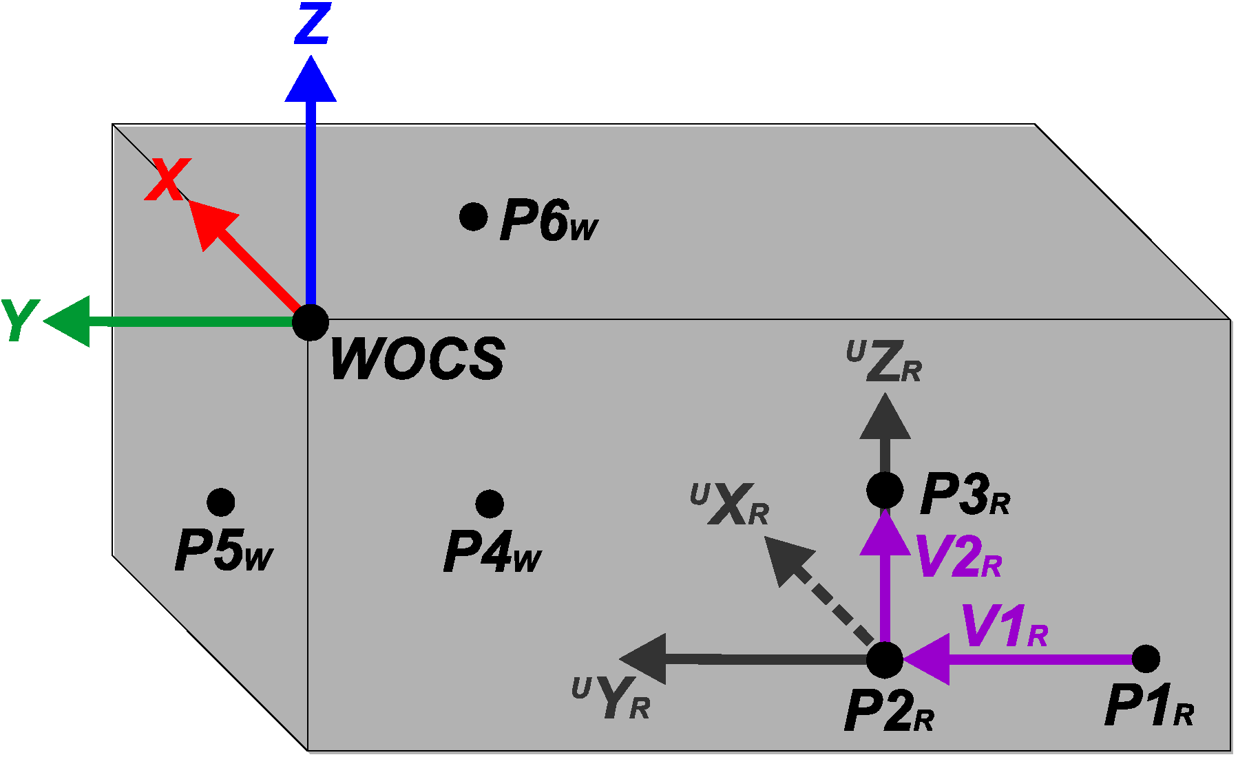
Figure 7 shows the positions of the measured points, the vectors used in the positional calibration calculations and the calibrated WOCS on a general work object geometry.
Figure 7.
A general work object, showing the positions of measurements P1-P6, the vectors used in the positional calibration calculations and the position and rotation of the calibrated Work Object Coordinate System (WOCS).
Figure 7.
A general work object, showing the positions of measurements P1-P6, the vectors used in the positional calibration calculations and the position and rotation of the calibrated Work Object Coordinate System (WOCS).
Starting with the three points
P1R,
P2R and
P3R, two vectors in the yz-plane of the sought WOCS,
V1R and
V2R, are calculated in the RBCS.
V1R is calculated from
P1R to
P2R using that
and
V2R is calculated from
P2R to
P3R using that
A normal vector to the yz-plane,
XR, directed in the positive x-axis direction of the sought WOCS, is then calculated in the RBCS as the cross product between
V1R and
V2R, knowing that
Assuming that two of the points on the work object side,
P1R and
P2R, are placed parallel to the y-axis direction of the sought WOCS,
V1R can be used as vector
YR, which is thus directed in the positive y-axis direction of the sought WOCS. A third vector,
ZR, which is perpendicular to
XR and
YR and directed in the positive z-axis direction of the sought WOCS, can now be calculated as the cross product between
XR and
YR, knowing that
These three vectors,
XR,
YR and
ZR, describe the orientation of the work object relative to the RBCS. Hence, the WOCS orientation can now be aligned with the work object orientation. This is done by first transforming
XR,
YR and
ZR to unit vectors
UXR,
UYR and
UZR. Then the rotational matrix from RBCS to WOCS,
RRW, is calculated from the unit vectors of the RBCS and the unit vectors from the WOCS, both described in the RBCS. The unit vectors of the RBCS,
UXR0,
UYR0 and
UZR0, are defined as
The elements in
RRW can now be calculated using the dot product, knowing that
Now the orientation of the WOCS relative to the RBCS can be described in Tait-Bryan z-y’-x’’ angles,
α,
β and
γ, which can be used in the robot programming, knowing that
Finally three new points,
P4W,
P5W and
P6W, measured in the orientation-adjusted WOCS and placed on three sides of the work object, are used. Thus, the WOCS origin can be adjusted and expressed in the earlier preliminary WOCS. This is done by using the x-coordinate of
P4W, the y-coordinate of
P5W and the z-coordinate of
P6W, all expressed in the assumed WOCS. The WOCS origin is then expressed in the RBCS, by using the rotational matrix from RBCS to WOCS,
RRW, and knowing that
3.2. The UU WEC Stator Section Example
In order for the cable winding automation to run smoothly, the maximum absolute positioning error at a stator slot hole should be about 1.0 mm with a 99.99% confidence level. This would result in about 50 positioning errors above 1.0 mm during one year of continuous production in one robot cell. Furthermore, the positional calibration method must be robust in terms of reasonable changes in the surrounding environment. It would also be favorably if the calibration method is fairly inexpensive and simple enough to be used with older robot models.
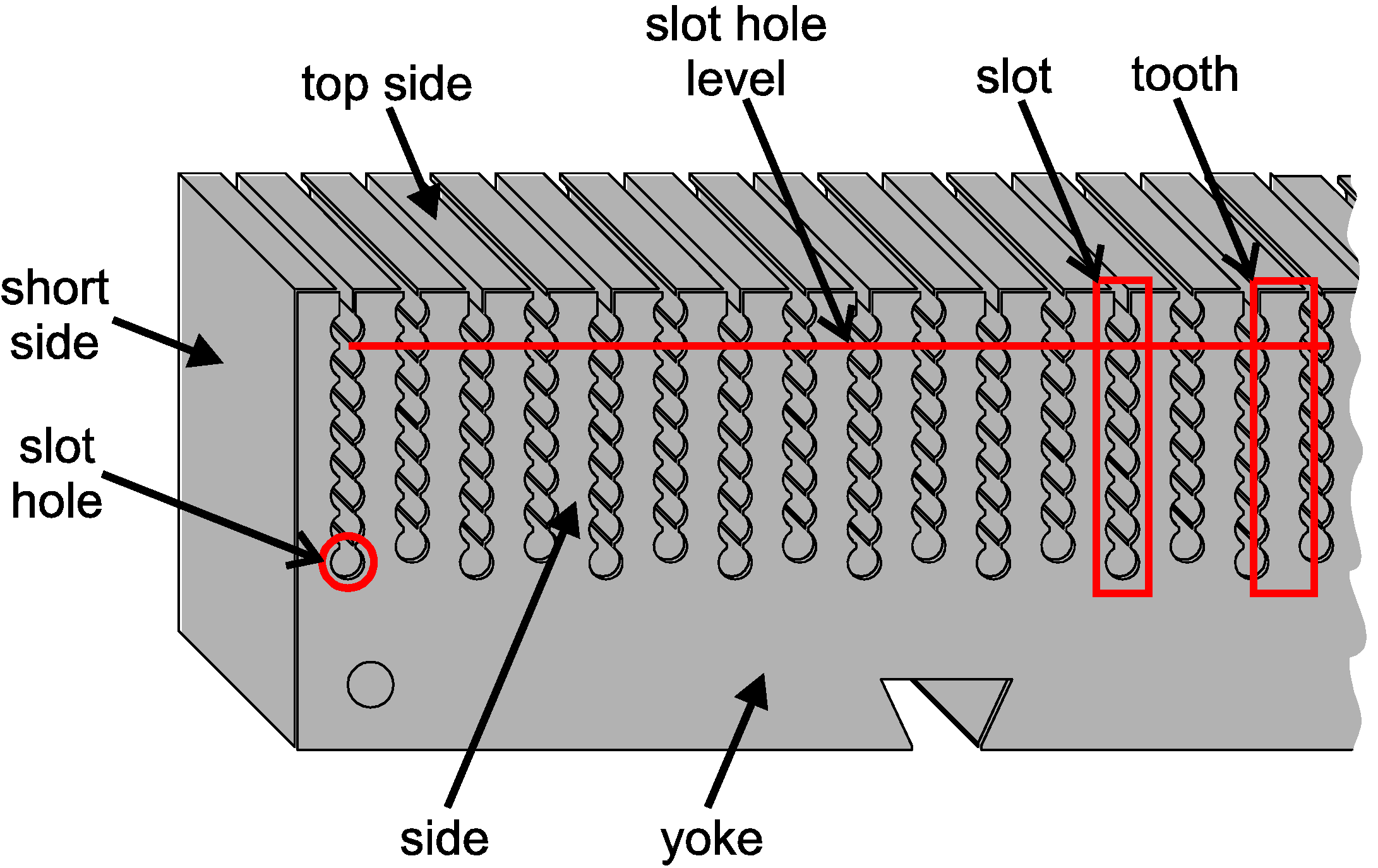
If the WOCS is positioned at a corner of the stator section and aligned with the stator section geometry, the absolute positioning error of the cable feeder tool after the positional calibration, relative to the stator section, will depend also on the rotational accuracy of the WOCS. Hence the absolute positioning error will increase with the distance to the WOCS origin. During the cable winding task, the absolute positioning error will therefore be largest at the slot hole being furthest away from the WOCS origin,
ε, see
Figure 8a. Another reason for limiting the orientation error of the calibration is the importance of feeding the cable straight into the slot holes. In order for the cable winding automation to run smoothly, the maximum rotational error, around the WOCS x-, y- and z-axes respectively, at a stator slot hole should be about 1.0° with a 99.99% confidence level.
Figure 8.
(a) The position of the measured points A–H on the stator section surface, the position of ε and the position and rotation of the calibrated WOCS. The tightening bolts, here preliminary placed in slots number 3, 15 and 31 together with bayonet pins and short cable parts, deforms the stator section somewhat in the x-direction of the WOCS. (b) The proximity sensor while positioned to search for the edge between the stator section side and top side by moving upwards over a stator tooth while being within the sensing distance to the stator section side.
In the cable winding robot cell, a stator section is automatically transported and positioned between the robots. A high precision fixture design is used to support the stator section, which is stacked from about 500 high precision stator sheets and held together by tightening bolts. Hence, the geometrical accuracy between the stator section slot holes is high while the thickness of the stacked stator section can vary somewhat. The position of the stator section in the robot cell can be assumed to vary only a few millimeters and less than one degree. However, when measuring the stator section geometry even a positioning deviation of less than a few millimeters might result in a measurement being taken with the proximity sensor positioned over a stator section slot hole. Since less ferromagnetic material is then available, the measurement might be incorrect relative to measurements taken over a solid part of the stator section.
Another problem is that the stator section side becomes a bit deformed by the tightening bolts which are used to hold together the stator section plates, see
Figure 8a. This deformation arises mainly in the x-direction of the WOCS and can be neglected in the y- and z-directions.
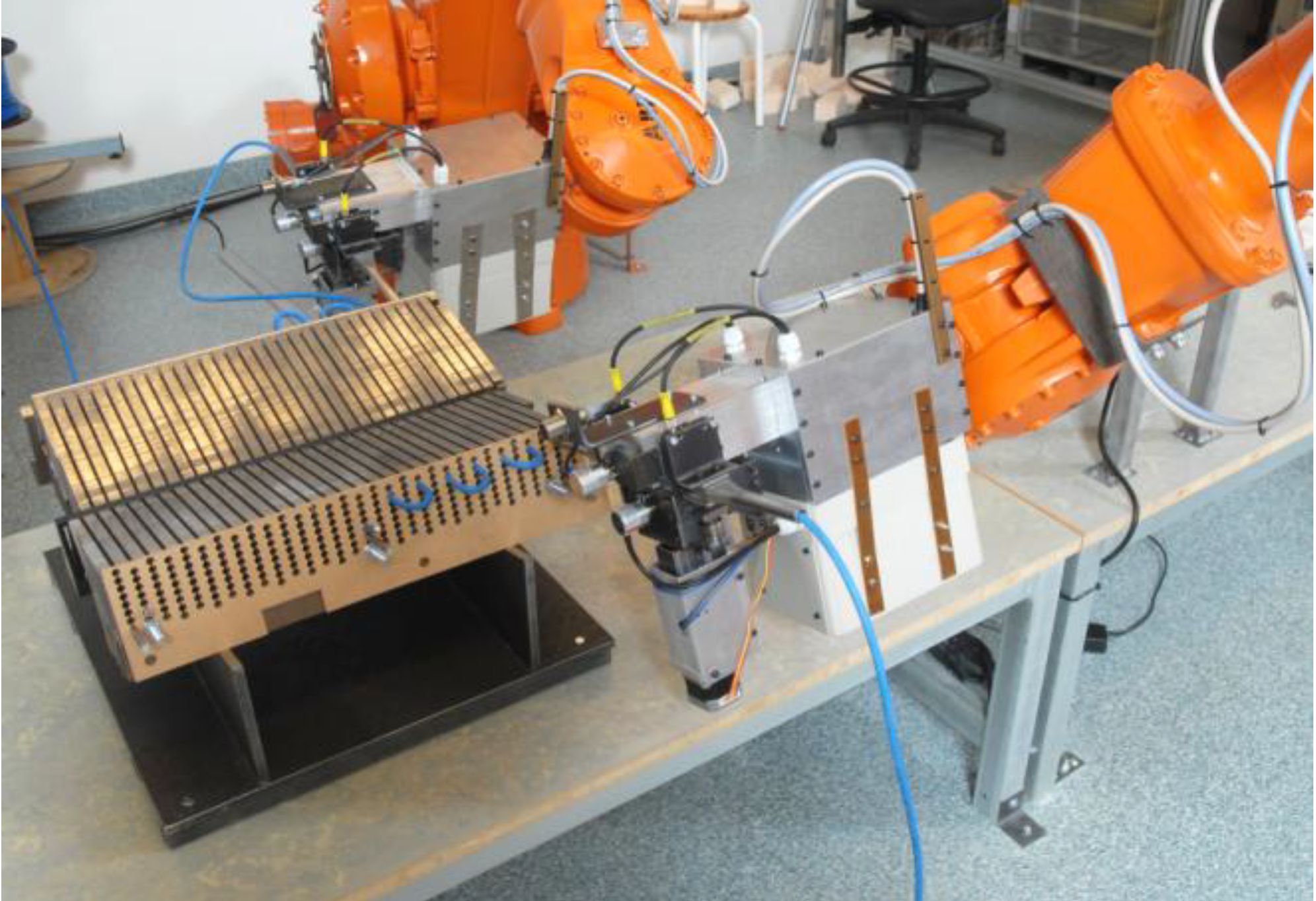
Due to the desired robot model and placement relative to the stator section, to the cable feeder tool design and to the stator section geometry, the robot reach for taking measurements with the proximity sensor was somewhat limited. As a consequence, measurements could not be taken on the top side of the stator section. In order to get the required measurements, the proximity sensor was instead moved upwards over the stator section side, within the sensing distance to the stator section, searching for the edge between the stator section side and the top side, see
Figure 8b.
In the UU WEC stator section positional calibration procedure, in total eight points on the stator section geometry are measured, see
Figure 8a. The positional calibration starts from an approximation of the stator section position in a preliminary WOCS. This approximation is first used to measure points
A and
B. In order to avoid that the measurements are disturbed by, e.g., slot holes on the stator section side, the measurements are taken on the yoke of the stator section. Knowing that the stator section is placed on a high precision fixture and table, measurements
A and
B are assumed to be placed parallel to the y-axis direction of the sought WOCS. Hence measurement
A can be used as
P1R and measurement
B can be used as
P2R.
P3R is calculated as a point 50 mm above
B at the stator section side surface by first calculating the WOCS rotation around the z-axis,
α1, from
A and
B and assuming the inclination of the stator side relative to the RBCS,
β1, to be 15°. We get
As a result, a preliminary calculation of the WOCS rotation can be made using Equations (1)–(9) a (11) and (12) and B can be used as P4W with Equation 10 to preliminary adjust the x-axis origin of the WOCS.
Next, measurement C is performed in the adjusted WOCS on the short side of the stator section and used as P5W with Equation (10) to preliminary adjust the y-axis origin of the WOCS.
Assuming that the WOCS rotation around the x-axis differs very little from the start approximation, measurements D and E can now be taken with high accuracy over a stator section tooth and used as P3R and P2R. By combining measurements A, B, D and E, the WOCS yz-plane can be adjusted to the side of the stator section. The previously calculated V1R is then used with the new P2R and P3R and Equations (2)–(9) to adjust the rotation of the WOCS, which is thereby adjusted around the WOCS y- and z-axes. Since measurement E is taken at a better defined position on the stator section side, this measurement can be used as P5W with Equation (10) to improve the position of the WOCS x-axis origin.
Next, point F is measured by moving the proximity sensor upwards, in the positive z-axis direction of the WOCS, over a stator section tooth within the sensing distance to the stator section side, beginning a few millimeters offset in the positive WOCS x-axis from point E. The edge is found as the end of the side surface is reached and the sensor stops detecting. Next, point G is measured and used as starting point in measuring point H, using the same procedure as for point F. The final WOCS rotation is now calculated using H as P1R, F as P2R and D as P3R with Equations (1)–(9), by inverting the direction of V2R. Finally, measurement H is used as P6Wz and measurements C and D are retaken and used as P5Wy and P4Wx with Equation (10) to decide the final position of the WOCS origin.
As the WOCS adjustment to the stator section geometry is finished, the varying x-direction offset of the stator section side surface is measured and calculated. This is done by using the x-component of the offset measurement,
PXWx, expressed in the WOCS, and repeating the measurement for every second stator tooth at two different slot hole levels on the stator section side. By combining these measurement results, the x-offset for each slot hole position can be estimated. These x-offset results are saved in a
m ×
n-matrix,
MXW, where the rows represent the slot hole layers and the columns represent the slot number. Thus, with
i and
j representing the slot hole layer and the slot number for an individual slot hole and
k and
l representing the slot hole level and the slot tooth number for an individual x-offset measurement, we get
where
Using the adjusted WOCS and the x-offset matrix, all slot hole positions can easily be calculated from knowing the stator section dimensions. To facilitate positioning during robotized cable winding, a new function is created in the robot programming. If given the desired slot number and slot hole layer, this function returns a robot target fitted at to the specified slot hole. The rotation of the robot target is aligned with the WOCS, while the position of the robot target is calculated as a geometrical offset in the y- and z-axes directions, and adjusted by the x-offset matrix in the x-axis direction, relative to the WOCS origin. If desired the function can create a robot target with a user defined distance and rotation relative to a slot hole. Hence, by using the presented positional calibration method and the described programming function, creating robot targets for positioning the cable feeder tool against different slot holes is very straightforward.
