Article

The Second Approximation of the Averaging Method in the Dynamics of Controlled Motions of Vibration Systems with Dry Friction

1
Department of Mechanical Engineering, Technische Universität Ilmenau, Max-Planck-Ring 12, 98693 Ilmenau, Germany
2
Laboratory of Robotics and Mechatronics, Institute for Problems in Mechanics of the Russian Academy of Sciences, 101-1 Vernadsky Ave, 119526 Moscow, Russia
*
Author to whom correspondence should be addressed.
Axioms 2025, 14(9), 694; https://doi.org/10.3390/axioms14090694
Submission received: 29 July 2025 / Revised: 6 September 2025 / Accepted: 10 September 2025 / Published: 12 September 2025
(This article belongs to the Special Issue Trends in Dynamical Systems and Applied Mathematics)

Abstract

The second approximation of the averaging method is constructed in the problem of motion along a horizontal rough plane of a vibration-driven mechanical system consisting of a carrying body (robot housing) in contact with the plane and two internal masses oscillating vertically and horizontally according to a harmonic law with the same frequency. In the absence of a phase shift in the first approximation, the directed motion of the system as a single whole (locomotion) cannot be detected. In the second approximation, an expression for the average velocity of motion is obtained. The values of velocity calculated using the obtained formula are in good agreement with the results of numerical calculations. The described technique for constructing the second approximation can be used to solve other problems with dry friction.

1. Introduction

The averaging method is a powerful analytical method used in mechanics. If a small perturbation is imposed on a system, then the evolution of quantities that are integrals in the unperturbed system over short time intervals will be small, although it can be significant over large time intervals. The averaging method allows one, under certain conditions, to obtain closed-form equations for the evolution that contain only smoothly changing variables. This method is based on the idea that the terms discarded during averaging lead only to small oscillations that are imposed on the evolution described by the averaged system. At present, variations of the averaging method under different names are widely used in many areas of mechanics [1,2,3,4]. A rigorous exposition of the averaging method with the formulation and proof of the corresponding theorems is contained in the classical works [5,6]. The averaging method in problems of directed motions (locomotion) with periodic action on the system and control of such motion was used in the works [7,8]. The first approximation occupies a special place. Firstly, as a rule, the first approximation gives an understanding of the qualitative behavior of the system as a whole. Secondly, stationary solutions of the averaged system are often of interest. Such solutions are found from a system of algebraic equations obtained by equating the right-hand side of the averaged equations to zero. However, in a number of cases, the first approximation fails to notice important features of the behavior of a mechanical system. For example, in the problem of peristaltic motion with small surface disturbances, in the first approximation, the average translation over the period (locomotion) is absent [9]. In [10], the problem of the motion of a body on a rough surface due to harmonic oscillations of horizontal and vertical internal masses with the same frequency, but with a phase shift, is considered. In the absence of a phase shift, in the first approximation, the average velocity over the period is zero, although numerical calculations have shown that the average translation over the period is different from zero. It should be noted that the classical theorems justifying the averaging method impose certain conditions on the right-hand sides of the differential equations of motion. In particular, the Lipschitz condition is assumed to be satisfied. This condition is obviously not satisfied for systems with dry Coulomb friction due to the discontinuity of the right-hand side in velocity and the presence of sticking zones. In a particular case, this problem is considered in [11,12,13,14]. In the work [15], it is shown that averaging is possible if the solution only “punctures” the discontinuity surface but does not lie on it; that is, the direction of motion changes without the presence of sticking zones. It is natural to assume that if the friction force is small compared with the exciting force, then the duration of the sticking zones will be of the same order of magnitude, and ignoring the sticking zones when using the averaging method will not introduce additional errors. In the present article, using the example of the problem considered in [10], the second approximation of the averaging method is constructed. In the first approximation, in the absence of a phase shift between the harmonic oscillations of the horizontal and vertical masses, the effect was not observed. It is shown that, under the condition of smallness of dry Coulomb friction forces compared with the exciting force, when calculating the stationary velocity of the system as a whole, ignoring sticking zones is possible not only in the first, but also in the second approximation of the averaging method. The technique used for calculating the stationary velocity in the second approximation can be used to solve other problems of the system’s motion on a rough surface with dry Coulomb friction in the case of a periodic disturbance with a zero mean value over the period.

2. Mathematical Model

Let us consider the mechanical system described in [10]. The system (a vibration-driven robot) consists of a carrying body (robot housing) and two masses interacting with the body and capable of moving horizontally and vertically according to a harmonic law with the same frequency, but with a phase shift relative to each other (Figure 1). The system performs plane-parallel motion in the vertical plane, and the carrying body moves rectilinearly along the horizontal plane. The force of dry (Coulomb) friction acts between the body and the plane. The internal masses are considered to be point masses. Let us introduce a fixed rectangular coordinate system O X Y , in which the O X axis is horizontal, and the O Y axis is directed vertically upward. Let us also introduce a coordinate system O ξ η , rigidly connected to the housing. The O ξ and O η axes are directed parallel to the O X and O Y axes, respectively. Let x be the displacement of the body relative to the fixed coordinate system, ξ 1 and η 2 be the coordinates of the corresponding masses in the moving reference system, m be the mass of the body, m 1 and m 2 be the masses of the internal bodies, and g be the acceleration due to gravity.
The motion of the body along the O X axis obeys the equation
( m + m 1 + m 2 ) x ¨ + m 1 ξ ¨ 1 = F C .
The force F C of dry Coulomb friction is expressed as [16,17,18]:
F C = k N sgn x ˙ , x ˙ 0 , F 0 , x ˙ = 0 | F 0 | k N , k N sgn F 0 , x ˙ = 0 | F 0 | > k N ,
where F 0 is the resultant of all forces applied to the body in the direction of the axis O X except for the dry friction force, N is the normal component of the force acting on the body from the plane, and k is the friction coefficient.
The forces F 0 and N are given by the expressions
F 0 = m 1 ( x ¨ + ξ ¨ 1 ) m 2 x ¨ , N = ( m + m 1 + m 2 ) g + m 2 η ¨ 2 .
Since the system moves without detaching from the plane, then the inequality N 0 must hold. Due to the relation (3), this condition imposes a limitation on the relative acceleration η ¨ 2 of the internal body with mass m 2 .
As was shown in [10], the expression for F 0 in (3) can be simplified to
F 0 = m 1 ξ 1 ¨ .
Indeed, let x ˙ be a piecewise continuous differentiable function. Suppose that x ˙ = 0 and x ¨ 0 at some point in time. Then in the neighborhood of this point, the function x ˙ ( t ) decreases (increases) and x ˙ 0 . Thus, the simultaneous conditions x ˙ = 0 and x ¨ 0 are possible only at isolated points. This circumstance is of no importance during integration and does not affect the nature of the motion of the mechanical system.
Let us introduce the notation
M = m + m 1 + m 2 , Φ x = m 1 ξ ¨ 1 , Φ y = m 2 η ¨ 2 .
Then the Equations (1)–(3) can be written as
M x ¨ = Φ x + F C ,
F C = k N sgn x ˙ , x ˙ 0 , Φ x , x ˙ = 0 | Φ x | k N , k N sgn Φ x , x ˙ = 0 | Φ x | > k N ,
N = M g Φ y , N 0 .
We will consider the case when the control forces Φ x and Φ y are harmonic functions of time with amplitudes F x and F y and the same frequency ω :
Φ x = F x sin ω t , Φ y = F y sin ( ω t + φ 0 ) , F x > 0 , F y 0 .
Here φ 0 is the phase difference between Φ x and Φ y .
The equations of motion of the system (1)–(3) in this case become
M x ¨ = F x sin ω t + F C ,
F C = k N sgn x ˙ , x ˙ 0 , F x sin ω t , x ˙ = 0 F x | sin ω t | k N , k N sgn ( sin ω t ) , x ˙ = 0 F x | sin ω t | > k N ,
N = M g + F y sin ( ω t + φ 0 ) , 0 F y M g .
We introduce the dimensionless (asterisked) variables and parameters as follows:
x * = M ω 2 F x x , t * = ω t , ε = k M g F x , α = F y M g .
Since we will use only dimensionless variables in the future, we will omit the asterisks.
Let x ˙ = V , then the equations of motion of the system (10)–(12) in dimensionless variables becomes
V ˙ = sin t + f C ,
f C = f sgn V , V 0 , sin t , V = 0 | sin t | f , f sgn ( sin t ) , V = 0 | sin t | > f ,
f = ε 1 + α sin ( t + φ 0 ) , α 1 .

3. A Note About Sticking Zones

The justification for the use of the averaging method for systems with dry friction causes difficulties due to the discontinuity of the right-hand side and the presence of sticking zones. In [15], the use of the averaging method is justified in the case where the solution “punctures” the discontinuity surface at a non-zero angle, i.e., does not lie on the discontinuity surface. For systems with dry friction, this condition means the absence of sticking zones. In [10], it was noted that if the friction force is small (of the order of ε ) compared with the exciting force, then the total duration of sticking zones over a period is also of the order of ε , and when calculating, in the first approximation, the stationary (average) velocity of interest to us over a period, the influence of sticking zones can be neglected. In the second approximation, the correction to the stationary (average) velocity calculated in the first approximation will also be of the order of ε , i.e., it will have the same order of smallness as the total duration of sticking zones over a period. Let us consider this issue in more detail.
The sticking zones are determined by the second condition (15). A necessary condition for the presence of sticking zones on the boundary of period T = 2 π is given by the inequality:
| sin t | f .
For sin t 0 , ( 0 t π ) , the condition (17) takes the form:
( 1 ε α cos φ 0 ) sin t ε α sin φ 0 cos t ε
or
sin ( t ψ 0 ) ε 1 2 ε α cos φ 0 + ε 2 α 2 , ψ 0 = arcsin ε α sin φ 0 1 2 ε α cos φ 0 + ε 2 α 2 .
On the interval 0 t π , the solution to the inequality (19) is given by
0 t ψ 1 + ψ 0 , π ψ 1 + ψ 0 t π , ψ 1 = arcsin ε 1 2 ε α cos φ 0 + ε 2 α 2 .
Similarly, for the case sin t < 0 ( π < t < 2 π ) , from the condition (19) we find
( 1 + ε α cos φ 0 ) sin t + ε α sin φ 0 cos t ε
or
sin ( t + χ 0 ) ε 1 + 2 ε α cos φ 0 + ε 2 α 2 , χ 0 = arcsin ε α sin φ 0 1 + 2 ε α cos φ 0 + ε 2 α 2 .
On the interval π < t < 2 π , the solution to the inequality (19) is defined by
π < t π + χ 1 χ 0 , 2 π χ 1 χ 0 t < 2 π , χ 1 = arcsin ε 1 + 2 ε α cos φ 0 + ε 2 α 2 .
As a result, the possible sticking zones for the period 0 t < 2 π are
0 t ψ 1 + ψ 0 , π ψ 1 + ψ 0 t π + χ 1 χ 0 , 2 π χ 1 χ 0 t < 2 π .
With an accuracy of up to ε 2 , the relations (24) can be written as
0 t ε ( 1 + α sin φ 0 ) , π ε ( 1 α sin φ 0 ) t π + ε ( 1 α sin φ 0 ) , 2 π ε ( 1 + α sin φ 0 ) t < 2 π .
Thus, the total duration of possible time intervals of sticking zones has an order of ε .
When using the averaging method, we ignore sticking zones, and the equation of motion (14) at all moments of time is represented by
V ˙ = sin t f sgn V .
It follows that in possible sticking zones, the following relationship is valid:
| V ˙ | | sin t | + | f | ε + ε ( 1 + α ) = ε ( 2 + α ) .
Based on the estimates (25) and (27), the following conclusion can be drawn: since after the possible vanishing of the velocity V for a time interval of an order of ε , the absolute value of the derivative | V ˙ | on this interval is also of an order of ε , the velocity on this interval will be of an order of ε 2 in accordance Lagrange’s finite increment theorem.
Since we are interested in the average velocity of the system in this interval, ignoring the sticking zones where the velocity vanishes introduces an error of the order of ε 2 . The sought correction to the average velocity of the system in the second approximation of the averaging method is of an order of ε . Thus, to calculate the average (stationary) velocity in the second approximation of the averaging method, we can consider Equation (26) instead of the equation of motion (14).
This circumstance allows us to use the standard technique of the averaging method to construct the second approximation [5].
First of all, the equation of motion (26) must be reduced to the so-called standard form. This is achieved by the following substitution:
U = V + cos t .
Then the equation of motion for the new variable becomes
U ˙ = ε 1 + α sin ( t + φ 0 ) sgn ( U cos t ) .
Note that the average values of V and U for the period T = 2 π are the same.

4. General Scheme for Constructing the Second Approximation

When constructing the second approximation, we will use the technique described in [5].
Let the system be given in standard form:
x ˙ = ε X ( x , t , ε ) ,
where X ( x , t , ε ) is a periodic function in t with period T.
Let us represent (30) as follows:
x ˙ = ε X 1 ( x , t ) + ε 2 X 2 ( x , t ) + ,
In the case under consideration, all X i ( x , t ) = 0 when i 2 ; that is,
x ˙ = ε X 1 ( x , t ) ,
where X 1 ( x , t ) is a periodic function in t with period T.
By replacing variables,
x = ξ + ε u 1 ( ξ , t ) + ε 2 u 2 ( ξ , t ) + ,
where all u i ( ξ , t ) are periodic in t functions with period T, the Equation (32) can be reduced to the form
ξ ˙ = ε A 1 ( ξ ) + ε 2 A 2 ( ξ ) + .
Since we will be interested in the second approximation, we will write out an expression for the values A 1 ( ξ ) and A 2 ( ξ ) at T = 2 π :
A 1 ( ξ ) = 1 2 π 0 2 π X 1 ( ξ , t ) d t = X ¯ 1 ( ξ ) , A 2 ( ξ ) = 1 2 π 0 2 π X 1 ( ξ , t ) ξ u 1 ( ξ , t ) u 1 ( ξ , t ) ξ A 1 ( ξ ) d t = F ¯ 2 ( ξ ) .
The function u 1 ( ξ , t ) is determined from the relation
u 1 ( ξ , t ) t = X 1 ( ξ , t ) X ¯ 1 ( ξ ) .
Thus, the original system (30) is replaced by the averaged (time-invariant) system (34).
Retaining the terms up to and including order k in the right-hand side of (34), we obtain the averaged system of the k-th approximation:
ξ k ˙ = ε A 1 ( ξ k ) + ε 2 A 2 ( ξ k ) + + ε k A k ( ξ k ) .
Comparing the expressions (34) and (37), we find
ξ ˙ ξ k ˙ ε k + 1 .
Then, on a time interval Δ t of order ε 1 , the following estimate holds:
ξ ( t ) ξ k ( t ) ε k .
The stationary solution of the averaged system (34) is found from the condition that the right-hand side is equal to zero. Thus, in the first approximation, we have
A 1 ( ξ 1 ) = X ¯ 1 ( ξ 1 ) = 0 ,
and in the second approximation,
A 1 ( ξ 2 ) + ε A 2 ( ξ 2 ) = X ¯ 1 ( ξ 2 ) + ε F ¯ 2 ( ξ 2 ) = 0 .
From the estimate (39) it follows that
ξ 2 ξ 1 ε ,
that is
ξ 2 = ξ 1 + ε Δ 1 .
Then, with an accuracy of up to values of an order of ε 2 , the expression (41) can be represented as follows:
A 1 ( ξ 1 ) + ε Δ 1 d A 1 ( ξ 1 ) d ξ + ε A 2 ( ξ 1 ) = 0 .
Since ξ 1 is a stationary solution in the first approximation, then, in accordance with the expression (40), the value A 1 ( ξ 1 ) = 0 , and then
Δ 1 = A 2 ( ξ 1 ) d A 1 ( ξ 1 ) d ξ .
Finally, the general formula for finding a stationary solution in the second approximation will look like
ξ 2 = ξ 1 ε A 2 ( ξ 1 ) d A 1 ( ξ 1 ) d ξ .

5. Calculation of the Stationary Solution in the Second Approximation

For the mechanical system under consideration, the right-hand side of Equation (32) is given by
X 1 ( ξ , t ) = 1 + α sin ( t + φ 0 ) sgn ( ξ cos t ) .
As already noted, in the first approximation, when the phase shift value is φ 0 = 0 and φ 0 = π , the stationary (average) velocity of the system as a whole is zero. In other cases, there is directed motion on average (locomotion). Mathematical difficulties in the second approximation become significant. For this reason, in the second approximation, we will limit ourselves to the case φ 0 = 0 . The case φ 0 = π , as follows from the expression (47), is obtained from the case φ 0 = 0 by replacing α with α .
The average value of the right-hand side (47) of the equation of motion (29) is [10]:
X ¯ 1 ( ξ ) = A 1 ( ξ ) = 1 , ξ < 1 , 2 π arcsin ξ , | ξ | 1 , 1 , ξ > 1 .
Then, in accordance with the expression (36), we have
u 1 ( ξ , t ) t = α sin t , ξ < 1 , ( 1 + α sin t ) sgn ( ξ cos t ) + 2 π arcsin ξ , | ξ | 1 , α sin t , ξ > 1 .
It follows from here that
u 1 ( ξ , t ) t = α sin t , ξ < 1 , 1 + α sin t + 2 π arcsin ξ , | ξ | 1 , 0 τ < γ , 2 π γ τ < 2 π , ( 1 + α sin t ) + 2 π arcsin ξ , | ξ | 1 , γ τ < 2 π γ , α sin t , ξ > 1 , γ = arccos ξ , τ = t 2 π · 2 π .
Here, { · } means the operation of taking the fractional part of a number.
Since we are interested in a stationary solution, in accordance with (48), we will assume that | ξ | < 1 . We will choose the integration constants from the continuity condition of the function u 1 ( ξ , t ) and its zero mean value over the period T = 2 π . As a result, we obtain
u 1 ( ξ , t ) = α cos t + 1 + 2 π arcsin ξ τ + 2 α ξ 2 arccos ξ + 2 α π + π , 0 τ < γ , α cos t 2 π arccos ξ · τ + 2 α π + π , γ τ < 2 π γ , α cos t + 1 + 2 π arcsin ξ τ + 2 α ξ + 2 arccos ξ + 2 α π 3 π , 2 π γ τ < 2 π .
Then
u 1 ( ξ , t ) ξ = 2 π · 1 1 ξ 2 · τ + 2 α + 2 1 ξ 2 , 0 τ < γ , 2 π · 1 1 ξ 2 · τ , γ τ < 2 π γ , 2 π · 1 1 ξ 2 · τ + 2 α 2 1 ξ 2 , 2 π γ τ < 2 π .
In accordance with (47), when φ 0 = 0 , we obtain
X 1 ( ξ , t ) ξ = ( 1 + α sin t ) · 2 δ ( ξ cos t ) .
Here δ ( · ) is a generalized function called the Dirac’s delta function.
In turn,
A 2 ( ξ ) = 1 2 π 0 2 π X 1 ( ξ , t ) ξ u 1 ( ξ , t ) d t A 1 ( ξ ) 2 π 0 2 π u 1 ( ξ , t ) ξ d t .
From (53), we find
0 2 π X 1 ( ξ , t ) ξ u 1 ( ξ , t ) d t = 2 0 2 π ( 1 + α sin t ) u 1 ( ξ , t ) δ ( ξ cos t ) d t .
According to the expression (48), we have
A 1 ( ξ ) = 2 π arcsin ξ .
Then, from the expression (54), we obtain
A 2 ( ξ ) = 2 π ( α ξ 2 α π 2 arcsin ξ 2 α π 1 ξ 2 · arccos ξ · arccos ( ξ ) + 2 arcsin ξ 1 1 ξ 2 + α π arccos ξ ) .
Now, in accordance with (41), we obtain an equation for finding ξ 2
arcsin ξ 2 + ε ( α ξ 2 2 α π 2 arcsin ξ 2 2 α π 1 ξ 2 2 · arccos ξ 2 · arccos ( ξ 2 ) + 2 arcsin ξ 2 1 1 ξ 2 2 + α π arccos ξ 2 ) = 0 .
From the expression (45), taking into account that ξ 1 = 0 , we find
Δ 1 = α 2 π + π 2 .
The stationary velocity of the system V ¯ in accordance with the expression (46) in the second approximation is given by
V ¯ = ε α 2 π + π 2 .

6. Comparison with the Results of Numerical Integration

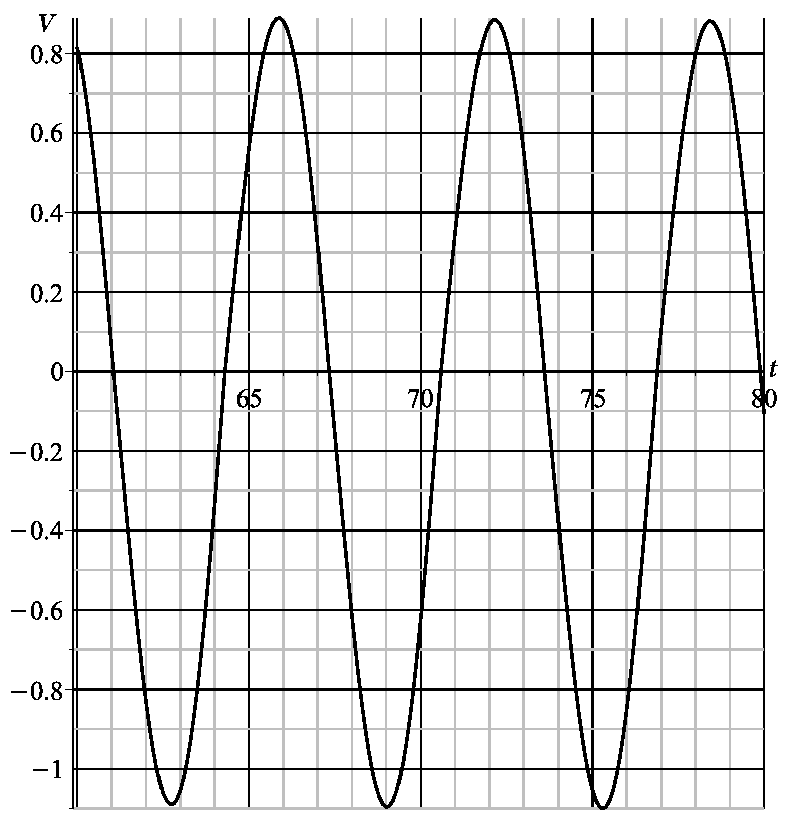
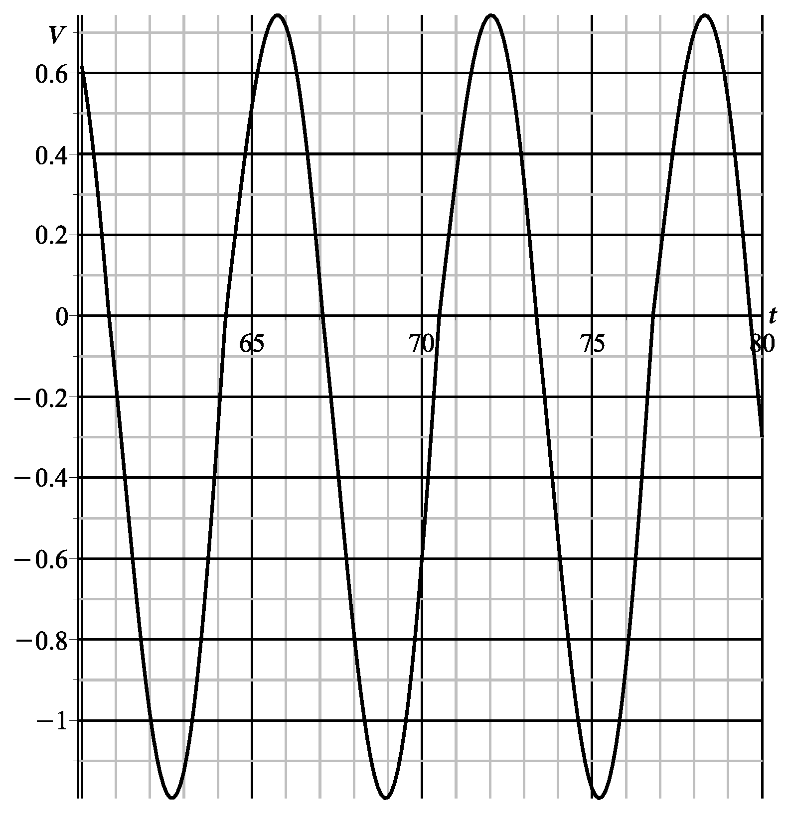
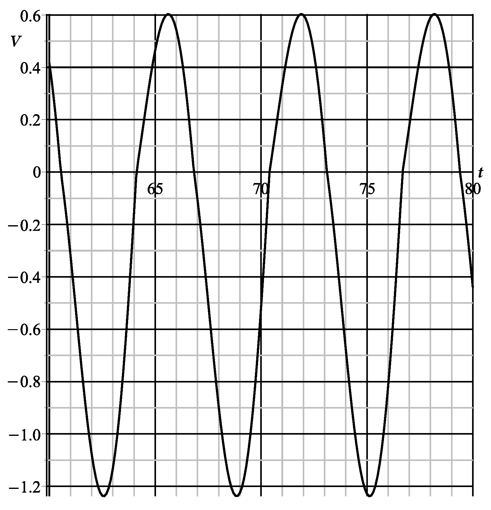
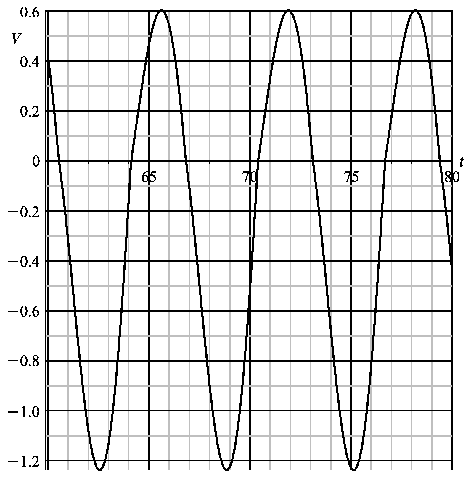
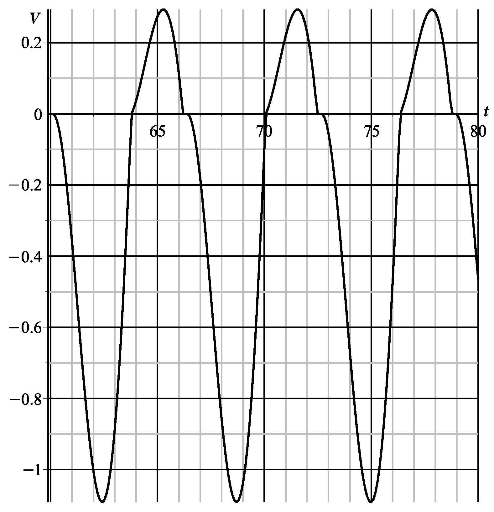
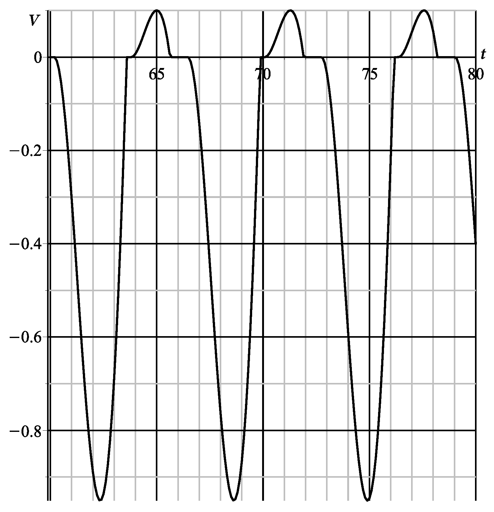
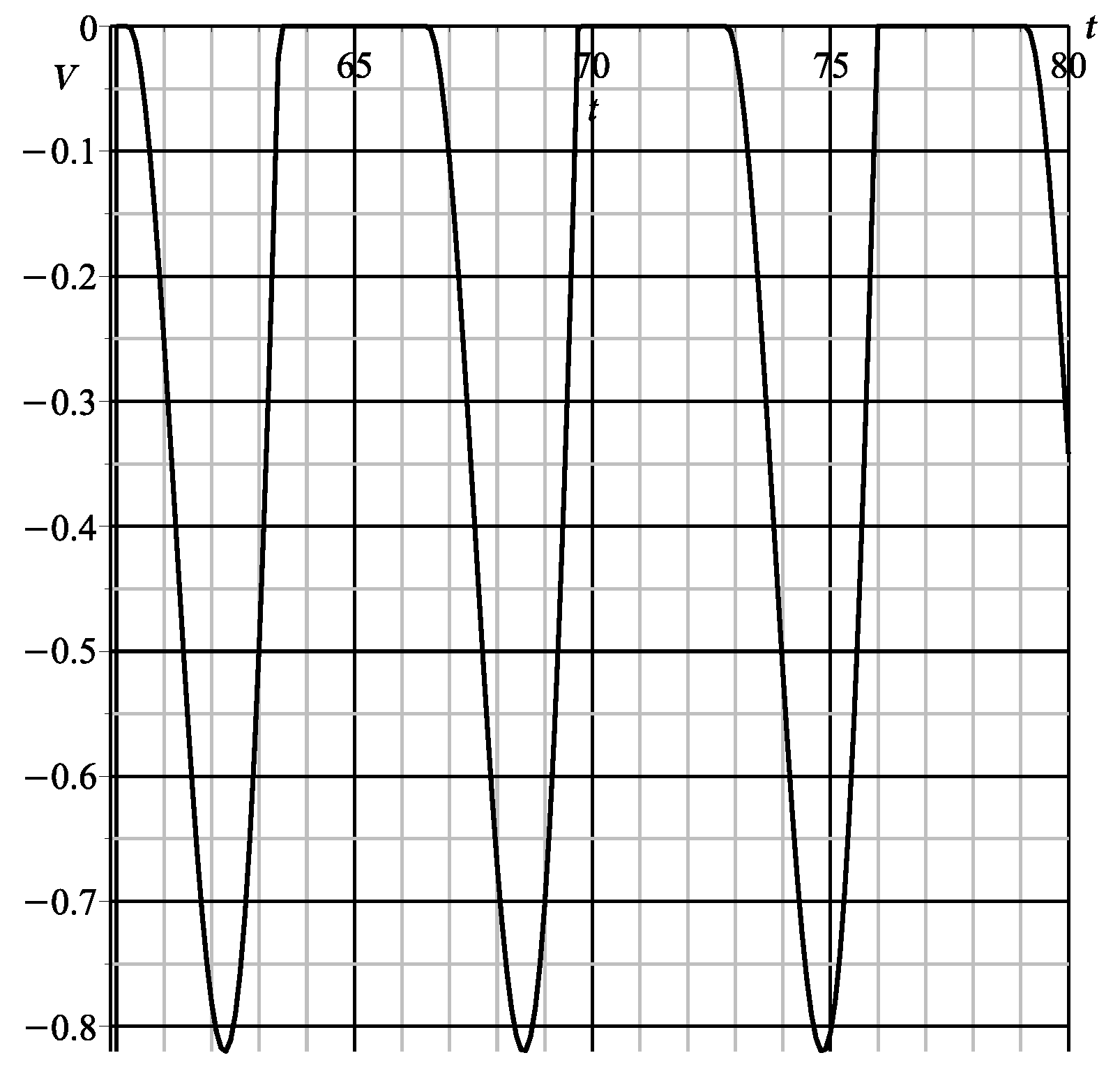
Figure 2, Figure 3, Figure 4, Figure 5, Figure 6, Figure 7 and Figure 8 show the graphs of the function V ( t ) obtained by numerical integration of the Equation (14) at φ 0 = 0 for different values of the parameter ε . The parameter α = 0.456 is taken to be the same as in [10], which corresponds to the prototype of the vibration-driven robot built at the Technical University of Ilmenau. For the selected time interval, the transient process has ended, and the motion has been established.
Table 1 presents the values of the average (stationary)velocity of motion V ¯ n u m obtained as a result of numerical integration of the equations of motion (14) and V ¯ a n a l , obtained analytically as a second approximation of the averaging method found from Equation (60), for different values of the parameter ε .
The table also presents the absolute Δ a b s and relative Δ r e l ( n u m ) , Δ r e l ( a n a l ) errors between the numerical and analytical calculations defined by the relations:
Δ a b s = | V ¯ a p p r V ¯ n u m | , Δ r e l ( n u m ) = Δ a b s | V ¯ n u m | · 100 % , Δ r e l ( a n a l ) = Δ a b s | V ¯ a n a l | · 100 % .
It follows from the calculations given that for small values of the parameter ε , we have good agreement between the average velocity obtained from the exact Equation (14) and the approximate (60). For all cases, the error does not exceed ε 2 .
For ε = 0.6 and ε = 0.7 (Figure 7 and Figure 8, respectively), the length of the stagnation zones becomes significant.

7. Conclusions

The second approximation according to the averaging method is constructed for the steady-state periodic solution of the differential equation that governs the motion of a vibration-driven locomotion system moving along a straight line on a rough horizontal plane. The excitation mode is assumed periodic. The friction between the underlying plane and the locomotor is modeled by Coulomb’s law, which implies discontinuity at zero velocity of the motion of the system. This discontinuity accounts for the sticking phenomenon that is observed in systems with dry friction. The system contains a small parameter defined by the ratio of the magnitude of the sliding friction force to the maximum magnitude (amplitude) of the excitation force. Dynamical systems with a small parameter are effectively treated by the method of averaging if the right-hand sides of the governing equations are smooth enough. However, because of Coulomb’s friction, the equation of motion of the system under consideration is a differential equation with a discontinuous right-hand side. For such equations, theorems of the method of averaging that give accuracy estimates for various-order approximations do not apply straightforwardly. However, in a number of cases, these theorems remain valid, which each time should be proved for the specific system under consideration. It is shown that the averaging technique can be applied to the examined locomotion system and that the sticking intervals do not affect the accuracy of the first and second approximations to the steady-state solution and can be ignored. It should be added that for some modes of excitation, the locomotion effect cannot be identified in the first approximation, while it is observed in numerical and physical experiments. This motivated us to construct the second approximation. The second approximation identifies the locomotion effect. A comparison of the approximate analytical solution obtained in the second approximation of the averaging method with the numerical solution shows good agreement. The technique described in this paper for constructing the second approximation for a steady-state velocity of the locomotion system can be applied to other vibrationally excited mechanical systems with dry friction.

Author Contributions

Writing—original draft, I.Z., N.B. and K.Z.; writing—review & editing, I.Z., N.B. and K.Z. All authors have read and agreed to the published version of the manuscript.

Funding

This research received no external funding.

Institutional Review Board Statement

Not applicable.

Informed Consent Statement

Not applicable.

Data Availability Statement

The original contributions presented in this study are included in the article. Further inquiries can be directed to the corresponding author(s).

Conflicts of Interest

The authors declare no conflict of interest.

References

  1. Blekhman, I.I. Vibrational Mechanics; World Scientific: Singapore, 2004. [Google Scholar]
  2. Fidlin, A. Nonlinear Oscillations in Mechanical Engineering; Springer: New York, NY, USA, 2005. [Google Scholar]
  3. Andrianov, I.; Awrejcewicz, J. Asymptotic Methods for Engineers; CRC Press: Boca Raton, FL, USA, 2024. [Google Scholar]
  4. He, J.-H. The homotopy perturbation method for nonlinear oscillators with discontinuities. Appl. Math. Comput. 2004, 151, 287–292. [Google Scholar] [CrossRef]
  5. Bogolubov, N.N.; Mitropolskii, Y.A. Asymptotic Methods in the Theory of Nonlinear Oscillations; Gordon and Breach: New York, NY, USA, 1961. [Google Scholar]
  6. Sanders, J.A.; Verhulst, F.; Murdock, J. Averaging Methods in Nonlinear Dynamical Systems; Springer: New York, NY, USA, 1985. [Google Scholar]
  7. Zimmermann, K.; Zeidis, I.; Behn, C. Mechanics of Terrestrial Locomotion; Springer: Berlin/Heidelberg, Germany, 2009. [Google Scholar]
  8. Chernousko, F.; Bolotnik, N. Dynamics of Mobile Systems with Controlled Configuration; Springer: Singapore, 2024. [Google Scholar]
  9. Zeidis, I.; Zimmermann, K. Ein mathematisches Modell für die peristaltische Bewegung als Grundlage für das Design wurmartiger Mikroroboter. Techn. Mech. 2000, 20, 73–80. [Google Scholar]
  10. Bolotnik, N.N.; Zeidis, I.M.; Zimmermann, K.; Yatsun, S.F. Dynamics of controlled motion of vibration-driven systems. J. Comput. Syst. Sci. Intern. 2006, 45, 157–167. [Google Scholar] [CrossRef]
  11. Fidlin, A. On the asymptotic analysis of discontinuous systems. ZAMM 2002, 82, 75–88. [Google Scholar] [CrossRef]
  12. Pilipchuk, V.N. Nonlinear Dynamics: Between Linear and Impact Limits; Springer: New York, NY, USA, 2010. [Google Scholar]
  13. Llibre, J.; Mereu, A.C.; Novales, D.D. Averaging theory for discontinuous piecewise differential systems. J. Diff. Equ. 2015, 258, 4007–4032. [Google Scholar] [CrossRef]
  14. Itikawa, J.; Llibre, J.; Novales, D.D. A new result on averaging theory for a class of discontinuous planar differential systems with applications. Rev. Matem. Iberoam. 2017, 33, 1247–1265. [Google Scholar] [CrossRef]
  15. Plotnikov, V.A.; Zverkova, T.S. Method of partial averaging in the systems of standard form with discontinuous right-hand sides. Ukr. Math. J. 1993, 18, 156–159. [Google Scholar] [CrossRef]
  16. Appel, P. Traité de Mécanique Rationnelle; Gauthier-Villars: Paris, France, 1893. [Google Scholar]
  17. Whittaker, E.T. A Treatise on the Analytical Dynamics of Particles and Rigid Dodies; Cambridge University Press: Cambridge, UK, 1917. [Google Scholar]
  18. Anh, L.X. Dynamics of Mechanical Systems with Coulomb Friction; Springer: Berlin/Heidelberg, Germany, 2003. [Google Scholar]
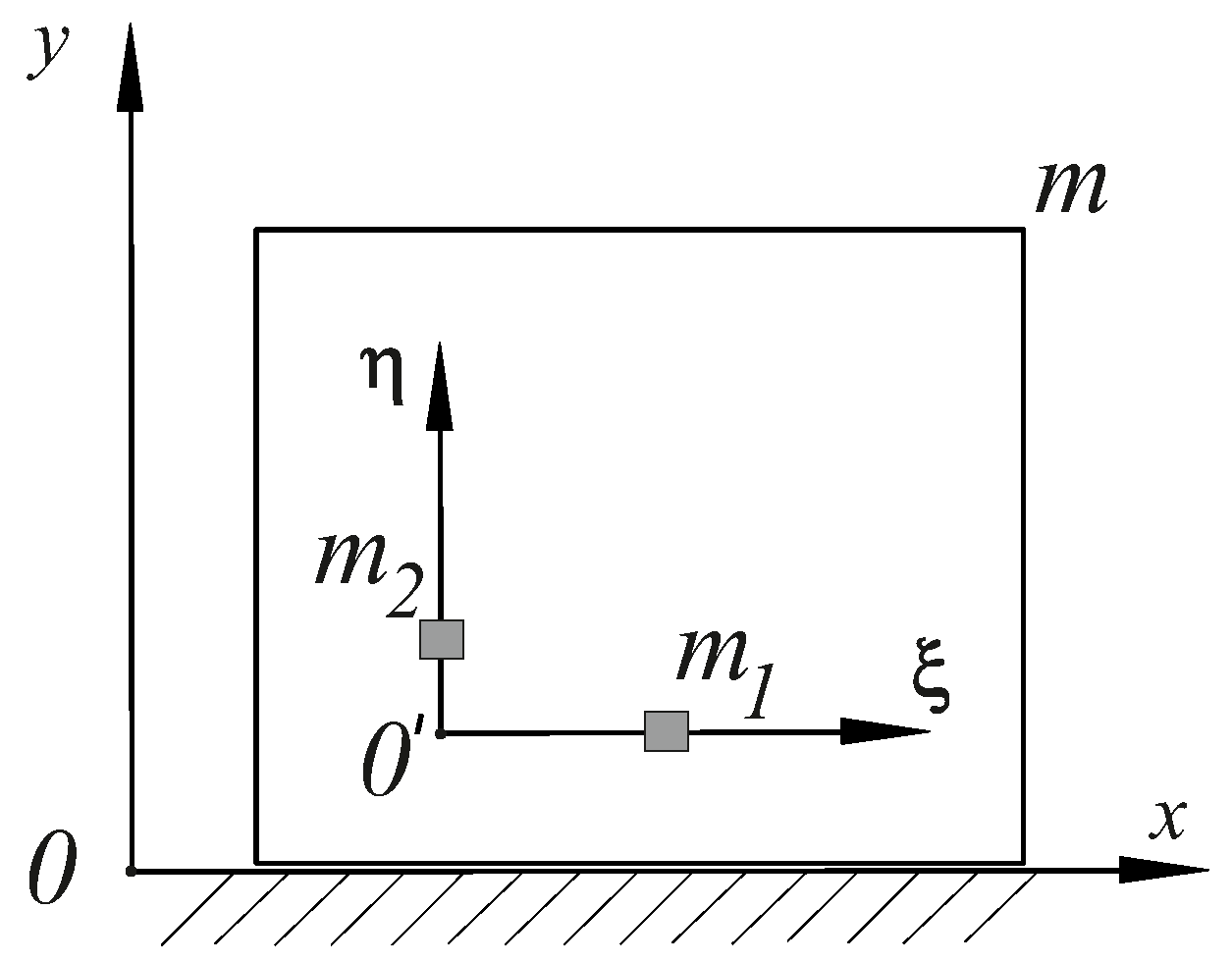
Figure 1. Mechanical system.
Axioms 14 00694 g001
Figure 2. Results of the numerical solution of the exact equation ( ε = 0.1).
Axioms 14 00694 g002
Figure 3. Results of the numerical solution of the exact equation ( ε = 0.2).
Axioms 14 00694 g003
Figure 4. Results of the numerical solution of the exact equation ( ε = 0.3).
Axioms 14 00694 g004
Figure 5. Results of the numerical solution of the exact equation ( ε = 0.4).
Axioms 14 00694 g005
Figure 6. Results of the numerical solution of the exact equation ( ε = 0.5).
Axioms 14 00694 g006
Figure 7. Results of the numerical solution of the exact equation ( ε = 0.6).
Axioms 14 00694 g007
Figure 8. Results of the numerical solution of the exact equation ( ε = 0.7).
Axioms 14 00694 g008
Table 1. Average velocity values depending on ε .
ε V ¯ num V ¯ appr Δ abs Δ rel ( num ) % Δ rel ( appr ) %
0.1− 0.0958− 0.10070.00495.114.87
0.2− 0.1910− 0.20130.01035.395.11
0.3− 0.2648− 0.30200.037214.0512.32
0.4− 0.3048− 0.40260.097832.0824.29
0.5− 0.2898− 0.50330.213573.6742.42
Disclaimer/Publisher’s Note: The statements, opinions and data contained in all publications are solely those of the individual author(s) and contributor(s) and not of MDPI and/or the editor(s). MDPI and/or the editor(s) disclaim responsibility for any injury to people or property resulting from any ideas, methods, instructions or products referred to in the content.