Abstract
This article describes an effective computing method for singularly perturbed parabolic problems with small negative shifts in convection and reaction terms. To handle the small negative shifts, the Taylor series expansion is used. The asymptotically equivalent singularly perturbed parabolic convection–diffusion–reaction problem is then discretized with the Crank–Nicolson method on a uniform mesh for the time derivative and a hybrid method on Shishkin-type meshes for the space derivative. The method’s stability and parameter-uniform convergence are established. To substantiate the theoretical findings, the numerical results are presented in tables and graphs are plotted. The present results improve the existing methods in the literature. Due to the effect of the small negative shifts in Examples 1 and 2, the numerical results using Shishkin and Bakhvalov–Shishkin meshes are almost the same. Since there are no small shifts in Examples 3 and 4, the numerical results using the Bakhvalov–Shishkin mesh are more efficient than using the Shishkin mesh. We conclude that the present method using the Bakhvalov–Shishkin mesh performs well for singularly perturbed problems without small negative shifts.
Keywords:
singularly perturbed problems; partial differential equation; negative shifts; hybrid numerical method; Shishkin-type meshes; right layer; functional-differential equation MSC:
35R10; 35B20; 35B25; 65M06; 65M12; 65M22
1. Introduction
Differential-difference equations are used to mathematically model a variety of situations in real life, like micro-scale heat transfer [1], the hydrodynamics of liquid helium [2], second-sound theory [2], optically bistable devices [3], diffusion in polymers [4], control of chaotic systems [5], and a variety of models for physiological processes or diseases [6,7]. A differential-difference equation is said to be retarded if the delay argument does not occur in the highest order derivative term; otherwise, it is said to be a neutral differential-difference equation. A differential-difference equation is a differential equation for which the evolution not only depends on the current state of the system but also on the past history [5]. A differential-difference equation involves subtracting or adding a small positive parameter, such as , to one or more arguments of the unknown function z or its derivatives. This parameter is considered to be a negative shift if it is subtracted, and a positive shift if it is added. A differential equation is referred to as a singularly perturbed differential-difference equation if it exhibits properties with both singular perturbation problems and differential-difference equations. A functional-differential equation is another name for a differential-difference equation. We introduce the following singularly perturbed parabolic functional differential with negative shifts in the convection and reaction terms:
subject to the initial condition
and the interval boundary conditions
where , for some fixed number and . The parameter is a perturbation parameter and () is a small delay parameter (or negative shift) satisfying . The functions , and are assumed to be sufficiently smooth and bounded to guarantee the existence of a unique solution, is assumed to satisfy for some constant , and (1) contains negative shifts in the convection and reaction terms. With the above conditions, the problem has a boundary layer near . When , (1) would reduce to the singularly perturbed parabolic differential equation.
Various numerical solutions have been developed in the literature for a singularly perturbed parabolic problem with a delay term and advance term in both reaction terms in [8,9,10,11,12,13,14,15,16,17,18,19,20,21]. Some numerical methods have been developed for a singularly perturbed parabolic problem with delay in the reaction terms only in [22] using a new class of non-standard finite difference methods based on interpolation, the –method, and Micken’s techniques; the implicit Euler method in temporal discretization; the hybrid scheme consisting of the midpoint upwind method in the outer region and the cubic spline method in the inner region on a Shishkin mesh for spatial discretization in [23]; and the implicit Euler method for the time direction and fitted exponential cubic spline method for space direction are developed in [24]. Some numerical methods are developed for solving different types of singularly perturbed problems in [25,26,27].
Different numerical methods for solving singularly perturbed parabolic functional-differential equations with negative shifts in convection and reaction terms of the form in (1)–(3) are constructed and analyzed in [28] using a three-step Taylor Galerkin finite element scheme-based monotone Schwarz iterative method, a complete flux scheme in [29], a domain decomposition Taylor Galerkin finite element approximation in [30], a finite element domain decomposition approximation in [31], the Crank–Nicolson method for time direction and upwind method on Shishkin mesh for space direction are used in [32], the –method in time and non-standard method in space directions are used in [33], the Crank–Nicolson method for time direction and exponentially fitted finite difference method for space direction are developed in [34], and the Crank–Nicolson method for time and midpoint upwind method on a Shishkin mesh with Richardson extrapolation in space direction are used in [35]. According to a number of studies, although these shifts are very small, they have significant effects on the solution and should not be ignored [36]. Therefore, it is crucial to look into robust numerical techniques for solving (1)–(3). To this end, we propose and analyze a Crank–Nicolson method in time direction and a hybrid numerical method on Shishkin-type meshes in space direction to solve the problem under consideration.
This paper is arranged as follows. Section 2 examines the solution’s bounds and derivatives. Section 3 describes the Shishkin-type meshes (Shishkin and Bakhvalov–Shishkin meshes) as well as the hybrid finite difference method. Section 4 examines the uniform convergence of the present method. Section 5 discusses numerical results using tables and figures.
Throughout the paper, C denotes a generic positive constant independent of , the space mesh parameters, and the time step.
2. The Continuous Problem
2.1. A Priori Estimates for the Negative Shifts
For the case , using Taylor series approximation for terms containing a delay is appropriate [37]. Now, approximating and yields the following:
Plugging (4) into (1)–(3), we obtain an asymptotically equivalent time-dependent singularly perturbed convection–diffusion–reaction continuous problem of the following form:
with the initial condition
and the boundary conditions
where and . Assume , where and are the lower bounds for and , respectively. Furthermore, we assume , which implies the occurrence of a boundary layer of width near .
2.2. Solution Bounds
The existence and uniqueness of the solution for (1)–(3) can be guaranteed by the sufficient smoothness of and as well as the compatibility condition at the corner points as stated below.
Now, we provide the bounds on the derivatives of the solution of (1)–(3). In order to obtain the bounds, one requires some information about the solution.
To show the bounds of the solution of (5)–(7), we assume, without loss of generality, . Since is sufficiently smooth, using the property of norm, we prove the following lemma:
Proof of Lemma 2.
From the inequality
we have
This implies that
Since and is bounded, it implies that
which is the required result. □
Lemma 3.
Let Θ be a sufficiently smooth function defined on D which satisfies , . Then, ; implies that , .
Proof of Lemma 3.
Assume such that It is clear that , i.e., . Since which implies that , and . Now,
which is a contradiction to the assumption . Hence, . □
The following stability bound is an immediate consequence of the above maximum principle for the solution of Equation (1).
Proof of Lemma 4.
We define two barrier functions as
After evaluating the barrier functions under the initial and boundary conditions, the required bound follows. □
3. The Discrete Problem
The time derivative is discretized using the Crank–Nicolson method with a uniform step size. Following this, the discretization of the space derivative is done via the hybrid method on Shishkin-type meshes.
3.1. Time Semi-Discrete Problem
The problem is discretized using the Crank–Nicolson method on an equidistant mesh for the time derivative. Now, using the mesh size , the interval is divided into N sub-intervals with spacing . Therefore, the time interval is given by
Thus, the mesh points for the time interval are given by . Now, the time semi-discrete problem on is given by
with semi-discrete conditions
where represents the semi-discrete numerical solution to (5) and (6) at the time level. We can rewrite (8) and (9) in the form
where , , and with semi-discrete conditions in (9). The time semi-discretization satisfies the following semi-discrete maximum principle.
Lemma 5.
Let be a smooth function of the semi-discrete problem such that , . If , then .
Proof of Lemma 5.
Assume such that and ; clearly, Therefore, and . Now, we have
which contradicts the assumption , . It immediately follows that . Thus, for . □
The local truncation error (LTE) of the Crank–Nicolson method for the time semi-discretization is given by , where is the numerical solution of the boundary value problem
with semi-discrete conditions
where represents the semi-discrete numerical solution to (5)–(6) at the time level. This error quantifies the contribution of each time step to the global error of the time semi-discretization.
Lemma 6.
The LTE bound in the time direction is given by
Proof of Lemma 6.
The LTE quantifies each time step to the global error given by . The global error is the measure of the contribution of the LTE at each time step, which is given by
Lemma 7.
The global error estimate at is bounded by
Proof of Lemma 7.
Using the local error estimate up to the time step given in Lemma 6, the global error estimate at the time step is given by
where C is a positive constant independent of and . □
Lemma 7 concludes second-order uniform convergence for the time semi-discretization process. The next theorem helps us to study the parameter-uniform convergence for space discretization. The following theorem is helpful to find the error bound in the semi-discrete problem.
Proof of Theorem 1.
See [38]. □
3.2. Shishkin-Type Solution Decomposition
Since the bounds on the derivatives of the solution are not sharp enough for the proof of parameter-uniform convergence, Shishkin-type decomposition is needed to derive stronger bounds. This is done by splitting the solution into a regular component and a singular component and doing error bounds separately for each. Let
where the regular component is the solution to the non-homogeneous equation
and the singular component is the solution to the homogeneous equation
Now, we state the bounds for regular and singular components.
Theorem 2.
Let be the regular solution. Then, and its derivative satisfy the bound
In general, the derivatives are bounded by
Proof of Theorem 2.
For the proof, one can refer to [34,38]. □
Proof of Theorem 3.
Consider the barrier function
Evaluating the barrier functions at the boundaries and on the whole domain together with the discrete maximum principle yields the required result for . For , one can see the proof in [38,39]. □
3.3. Fully Discrete Problem
In this subsection, the space domain is discretized via layer-adapted Shishkin-type meshes of Shishkin and Bakhvalov–Shishkin meshes. The space domain is split into two sub-domains with an outer region and with a boundary layer region, where is the transition parameter, which separates the coarse and fine portions of the mesh. Now, the space domain is given by
Shishkin-type meshes are characterized by the Shishkin mesh transition parameter. Therefore, the transition parameter for all Shishkin-type meshes is given by
where denotes a constant that represents the order of the method and depends on and . Here, is the number of mesh intervals in the space direction. The mesh points for the Shishkin mesh are defined as
for being a positive even integer. From the definition of , we denote the space mesh size as follows:
With the same transition parameter, the mesh points for the Bakhvalov–Shishkin mesh are defined as
From the definition of , we denote the space mesh size as follows:
The analysis has been carried out by assuming that ; otherwise, is exponentially large compared to . It is clear from the above equation that , and the uniform mesh can be obtained by choosing . We define the discretized domain . Before formulating the numerical method, we introduce the difference operators for a given mesh function as follows:
where . Now, we discretize (8) and (9) in the space direction by means of a hybrid numerical scheme on a Shishkin-type mesh, where we use the central difference scheme in the boundary layer region and the midpoint upwind scheme [40] in the outer region. Let the fully discrete approximation be denoted as for the semi-discrete form . The totally discrete numerical scheme now takes the following form:
Multiplying both sides of the above equation by 2, we obtain
where
with the following discrete conditions:
Equation (17) can be written as follows:
Equation (19) yields the following tridiagonal system of equations:
with the discrete conditions in (18) and where the coefficients for are given by
and the coefficients for are given by
The right-hand side is given by
We used the following notations: The coefficient matrix of the discrete scheme in (20) with the discrete boundary conditions in (18) gives linear equations. The coefficient matrix at each time level is diagonally dominant and satisfies the M-matrix criterion. We use the Thomas algorithm to solve the linear equations since the matrix inversion method of solving the linear equations is sensitive to round-off errors.
4. Convergence Analysis
In this section, the stability of the present method is discussed, and, by using the truncation error, we obtain the parameter-uniform error estimate. The tridiagonal systems in (18) and (20) have the following properties. Suppose and ; then, we have
The M-matrix properties are thus satisfied by the tridiagonal matrix in (20). The solution Z of (17) can be decomposed into the regular and singular components R and S, respectively, where and R is the solution of the following non-homogeneous problem on :
and S satisfies
where is defined in the form
Similarly, is defined in the form above. The error can be written in the form
The error for the singular and regular components may now be estimated independently.
Theorem 4.
The error bound in the regular component for the Shishkin mesh is given by
and, for the Bakhvalov–Shishkin mesh, is given by
Proof of Theorem 4.
The truncation error for the regular component can be expressed as follows:
for . Firstly, considering the case (i.e., ), from (26), we have
Rearranging the terms in the above equation, we have
Using the Taylor series expansion for the last two terms in (27) and applying the modulus, we obtain
The Taylor series expansion for the first two terms in (27), together with the triangular inequality and the estimate in (28), yields
for . Using Lemma 7 and the fact that , we obtain
Since the discrete maximum principle is satisfied by the operator , the inequality in (30) simplifies to
on the Shishkin mesh. Using the same manner and the fact that , we can obtain the following bound:
on the Bakhvalov–Shishkin mesh. Secondly, considering the case (i.e., ), from (26), we have
Using the same method of analysis as used for and using Lemma 7 for the derivatives
for . Using Lemma 7 and the fact that , we obtain
Since the operator satisfies the discrete maximum principle, the inequality in (34) reduces to
on the Shishkin mesh. Continuing in the same manner and using the fact that , we can obtain the following bound
on the Bakhvalov–Shishkin mesh. □
Theorem 5.
The error bound in the singular component for the Shishkin mesh is given by
and, for the Bakhvalov–Shishkin mesh, is given by
Proof of Theorem 5.
Using the continuous solution decomposition in (16) and the difference equation in (24), we derive the error bound for the singular component as
As done in [40], the right-hand side of (37) could possibly represent the truncation error of the two boundary value problems by fixing t. As a result, we obtain
for . Using the fact that the discrete operator satisfies the discrete maximum principle and the inverse operator is uniformly bounded, it immediately follows that (38) becomes
for the Shishkin mesh. Following a similar pattern and using the fact that and , we can obtain the following bound
for the Bakhvalov–Shishkin mesh. Putting (31), (35), and (39) in (25) completes the proof of the error bound for the Shishkin mesh. The proof of the error bound for the Bakhvalov–Shishkin mesh is completed using (32), (36), and (40) in (25). □
The main result of our studies is the parameter-uniform convergence of the numerical solution, which is addressed by the following theorem.
Theorem 6.
Proof of Theorem 6.
The proof immediately follows from Theorems 4 and 5. □
5. Numerical Computations and Discussion
In this section, we carry out numerical computations to corroborate the performance of the present method with the theoretical results discussed in the previous sections.
Example 1.
Consider a singularly perturbed parabolic problem [35]
Example 2.
Consider a singularly perturbed parabolic problem [35]
Since the exact solutions for the Examples 1 and 2 are not available, we use the following double mesh principle to calculate the maximum absolute errors for each as
where is the numerical solution with mesh points and is the numerical solution at the finer mesh with mesh points. The following formula is used to calculate -maximum errors:
Furthermore, the numerical rate of convergence is computed by
The –maximum rates of convergence are calculated using
To investigate the effect of small negative shifts on numerical solutions and the practicality of the present method, we considered the singularly perturbed parabolic problem without small negative shifts. In this scenario, replacing by with is the same for the continuous problem, formulation of numerical method, and convergence analysis.
Example 3.
Example 4.
Consider a singularly perturbed parabolic problem [38]
where the source function and the initial function are chosen from the analytical solution given by
Since the exact solution for the Example 4 is available, the maximum absolute errors for each are calculated as
where is the numerical solution with mesh points and is the exact solution. Similarly, formulas in (42)–(44) are used.
Table 1 and Table 2 indicate the generated maximum point-wise errors and uniform errors for Examples 1 and 2, respectively. Table 3 and Table 4 demonstrate the comparison of maximum point-wise errors and rates of convergence using the present method and other methods in the literature. Figure 1 and Figure 2 display the numerical simulations for Examples 1 and 2. The maximum point-wise errors for Examples 3 and 4 are provided in Table 5 and Table 6 to investigate the effect of small negative shifts on numerical solutions and the feasibility of the present method. Table 7 and Table 8 show the comparison of maximum point-wise errors and convergence rates for Examples 3 and 4. Figure 3 and Figure 4 depict the numerical simulations for Examples 3 and 4, respectively. Figure 1, Figure 2, Figure 3 and Figure 4 show the formation of a strong boundary layer near as . Figure 5, Figure 6, Figure 7 and Figure 8 exhibit the log–log scale plots of the maximum errors for each Example. The log–log plots suggest the theoretical (green-colored) and numerical (the other colors) errors. These log–log plots suggest the uniform convergence of the method. For values equal to , and , the maximum point-wise errors are almost the same. This causes overlapping in the log–log plot. Due to this reason, we observe a single curve for numerical results (purple-colored overlapped numerical results for , and ) and a single curve for theoretical results as stated in Theorem 6 (red-colored). Due to this overlapping, we have only two curves (line graphs) in all log–log plots. Figure 9 depicts the effect of the perturbation parameter and small negative shifts via line graphs for Examples 1 and 2, while Figure 10 shows the effect of the perturbation parameter through line graphs for Examples 3 and 4, respectively. As the perturbation parameter size decreases, the layer thickness increases. Since we have not calculated the maximum errors for in all Tables, we have not included the rate of convergence () in the last rows. This is because of the low precision in our computer memory. When the number of mesh points increases, our computer becomes busy.

Table 1.
Computations of , and using , for Example 1.

Table 2.
Computations of , and using , for Example 2.

Table 3.
Comparison of and using , for Example 1.

Table 4.
Comparison of and using , for Example 2.
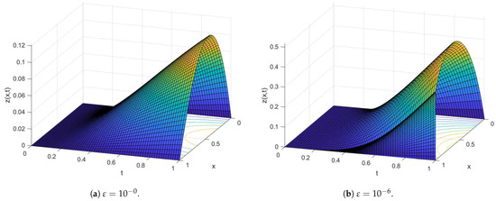
Figure 1.
Surface plot using and for Example 1.
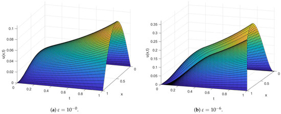
Figure 2.
Surface plot using and for Example 2.

Table 5.
Computations of , and using , for Example 3.

Table 6.
Computations of , and using , for Example 4.

Table 7.
Comparison of maximum errors for Example 3 with [39].

Table 8.
Comparison of maximum errors for Example 4.
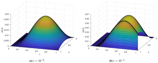
Figure 3.
Surface plot using and for Example 3.
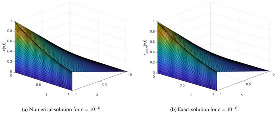
Figure 4.
Surface plot using and for Example 4.
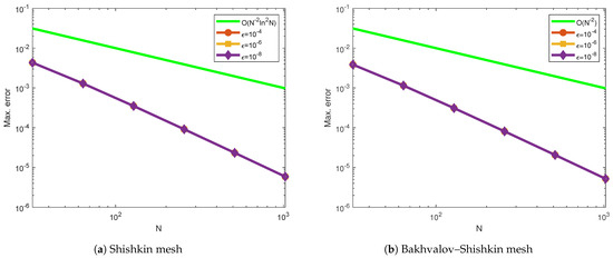
Figure 5.
Log–log plot of the maximum point-wise errors using for Example 1.
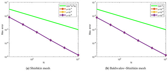
Figure 6.
Log–log plot of the maximum point-wise errors using for Example 2.
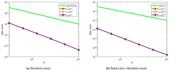
Figure 7.
Log–log plot of the maximum point-wise errors using for Example 3.
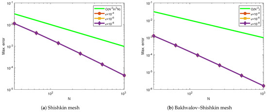
Figure 8.
Log–log plot of the maximum point-wise errors using for Example 4.
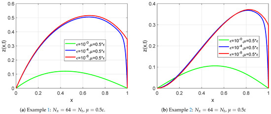
Figure 9.
Effect of the perturbation parameter and the delay parameter on the solution.
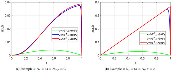
Figure 10.
Effect of the perturbation parameter on the numerical solution.
6. Conclusions
This study presents a computational method for a singularly perturbed parabolic functional differential equation with small negative shifts. The terms involving small negative shifts are approximated using the Taylor series approximation. The resulting singularly perturbed parabolic convection–diffusion–reaction equation is discretized by a Crank–Nicolson method in the time direction on a uniform mesh and a hybrid difference method on Shishkin-type meshes in the space direction. The stability and uniform convergence of the present method are established very well. Theoretically, we have proved that the present method provides an almost-second-order –uniform convergence using a Shishkin mesh and second-order –uniform convergence using a Bakhvalov–Shishkin mesh. To validate the applicability of the present method, Examples 1 and 2 were computed for different values of the perturbation parameter and small negative shifts. As can be observed from Table 1, Table 2, Table 3 and Table 4, maximum point-errors and rate of convergence using Shishkin and Bakhvalov–Shishkin meshes are almost the same for Examples 1 and 2. This is the effect of the small negative shifts in the governing differential equation. Since there are no small shifts in the governing differential equation for Examples 3 and 4, the maximum point-errors and rate of convergence using the Bakhvalov–Shishkin mesh are more efficient than using the Shishkin mesh. The Bakhvalov–Shishkin mesh produces the best solutions for the Examples 3 and 4 because there are no small negative shifts.
Author Contributions
Conceptualization and formal analysis, A.A.A.G. and F.W.G.; methodology, software, visualization, and writing—original draft preparation, A.A.A.G., F.W.G. and H.J.A.S.; investigation, supervision, writing—review and editing draft preparation, A.A.A.G., F.W.G. and H.J.A.S.; resources, project administration, funding acquisition, A.A.A.G. All authors have read and agreed to the published version of this manuscript.
Funding
This work was supported by the Deanship of Scientific Research, Vice Presidency for Graduate Studies and Scientific Research, King Faisal University, Saudi Arabia [Grant No. KFU251209].
Data Availability Statement
Data are contained within the article.
Acknowledgments
The authors are grateful to the referees for their valuable suggestions and comments.
Conflicts of Interest
The authors declare no conflicts of interest.
References
- Tzou, D.Y. Macro-to Microscale Heat Transfer; CRC Press: Boca Raton, FL, USA, 1997. [Google Scholar]
- Joseph, D.D.; Preziosi, L. Heat waves. Rev. Mod. Phys. 1989, 61, 41, Erratum in Rev. Mod. Phys. 1990, 62, 375–391. [Google Scholar] [CrossRef]
- Derstine, M.W.; Gibbs, H.M.; Hopf, F.A.; Kaplan, D.L. Bifurcation gap in a hybrid optically bistable system. Phys. Rev. A 1982, 26, 3720. [Google Scholar] [CrossRef]
- Liu, Q.; Wang, X.; De Kee, D. Mass transport through swelling membranes. Int. J. Eng. Sci. 2005, 43, 1464–1470. [Google Scholar] [CrossRef]
- Liao, X. Hopf and resonant codimension two bifurcation in van der Pol equation with two time delays. Chaos Solitons Fractals. 2005, 23, 857–871. [Google Scholar] [CrossRef]
- Mackey, M.C.; Glass, L. Oscillation and chaos in physiological control systems. Science 1977, 197, 287–289. [Google Scholar] [CrossRef] [PubMed]
- Lasota, A.; Wazewska, M. Mathematical models of the red blood cell system. Mat. Stos. 1976, 6, 25–40. [Google Scholar]
- Ramesh, V.; Kadalbajoo, M.K. Upwind and midpoint upwind difference methods for time-dependent differential difference equations with layer behavior. Appl. Math. Comput. 2008, 202, 453–471. [Google Scholar] [CrossRef]
- Kumar, D.; Kadalbajoo, M.K. A parameter-uniform numerical method for time-dependent singularly perturbed differential-difference equations. Appl. Math. Model. 2011, 35, 2805–2819. [Google Scholar] [CrossRef]
- Bansal, K.; Sharma, K.K. Parameter uniform numerical scheme for time dependent singularly perturbed convection-diffusion-reaction problems with general shift arguments. Numer. Algorithms. 2017, 75, 113–145. [Google Scholar] [CrossRef]
- Kumar, D. An implicit scheme for singularly perturbed parabolic problem with retarded terms arising in computational neuroscience. Numer. Methods Partial. Differ. Equ. 2018, 34, 1933–1952. [Google Scholar] [CrossRef]
- Nageshwar Rao, R.; Podila, P.C. Fitted numerical methods for singularly perturbed one-dimensional parabolic partial differential equations with small shifts arising in the modelling of neuronal variability. Differ. Equ. Dyn. Syst. 2019, 27, 1–18. [Google Scholar] [CrossRef]
- Gupta, V.; Kumar, M.; Kumar, S. Higher order numerical approximation for time dependent singularly perturbed differential-difference convection-diffusion equations. Numer. Methods Partial. Differ. Equ. 2018, 34, 357–380. [Google Scholar] [CrossRef]
- Podila, P.C.; Kumar, K. An adaptive mesh method for time dependent singularly perturbed differential-difference equations. Nonlinear Eng. 2019, 8, 328–339. [Google Scholar]
- Ramesh, V.; Priyanga, B. Higher order uniformly convergent numerical algorithm for time-dependent singularly perturbed differentialdifference equations. Differ. Equ. Dyn. Syst. 2021, 29, 239–263. [Google Scholar] [CrossRef]
- Shivhare, M.; Podila, P.C.; Ramos, H.; Vigo-Aguiar, J. Quadratic B-spline collocation method for time dependent singularly perturbed differential-difference equation arising in the modeling of neuronal activity. Numer. Methods Partial. Differ. Equ. 2023, 39, 1805–1826. [Google Scholar] [CrossRef]
- Daba, I.T.; Duressa, G.F. Extended cubic B-spline collocation method for singularly perturbed parabolic differential-difference equation arising in computational neuroscience. Int. J. Numer. Method Biomed. Eng. 2021, 37, e3418. [Google Scholar] [CrossRef] [PubMed]
- Takele Daba, I.; File Duressa, G. A hybrid numerical scheme for singularly perturbed parabolic differential-difference equations arising in the modeling of neuronal variability. Comput. Math. Methods 2021, 3, e1178. [Google Scholar] [CrossRef]
- Daba, I.T.; Duressa, G.F. Uniformly convergent numerical scheme for a singularly perturbed differential-difference equations arising in computational neuroscience. J. Appl. Math. Inform. 2021, 39, 655–676. [Google Scholar]
- Woldaregay, M.M.; Duressa, G.F. Uniformly convergent hybrid numerical method for singularly perturbed delay convection-diffusion problems. Int. J. Differ. Equ. 2021, 2021, 6654495. [Google Scholar] [CrossRef]
- Daba, I.T.; Duressa, G.F. Collocation method using artificial viscosity for time dependent singularly perturbed differential–difference equations. Math. Comput. Simul. 2022, 192, 201–220. [Google Scholar] [CrossRef]
- Bansal, K.; Sharma, K.K. ε-uniform numerical technique for the class of time dependent singularly perturbed parabolic problems with state dependent retarded argument arising from generalised steins model of neuronal variability. Differ. Equ. Dyn. Syst. 2019, 27, 113–140. [Google Scholar] [CrossRef]
- Daba, I.T.; Duressa, G.F. Hybrid algorithm for singularly perturbed delay parabolic partial differential equations. Int. J. (AAM) 2021, 16, 21. [Google Scholar]
- Daba, I.T.; Duressa, G.F. A robust computational method for singularly perturbed delay parabolic convection-diffusion equations arising in the modeling of neuronal variability. Comput. Methods Differ. Equ. 2022, 10, 475–488. [Google Scholar]
- Vrabel, R. Lower and upper solution method for semilinear, quasi-linear and quadratic singularly perturbed Neumann boundary value problems. Axioms 2023, 12, 154. [Google Scholar] [CrossRef]
- Kalimbetov, B.; Safonov, V.; Zhaidakbayeva, D. Asymptotic solution of a singularly perturbed integro-differential equation with exponential inhomogeneity. Axioms 2023, 12, 241. [Google Scholar] [CrossRef]
- Arumugam, P.; Thynesh, V.; Muthusamy, C.; Ramos, H. A quintic spline-based computational method for solving singularly perturbed periodic boundary value problems. Axioms 2025, 14, 73. [Google Scholar] [CrossRef]
- Kumar, B.R.; Kumar, S. Convergence of three-step Taylor Galerkin finite element scheme based monotone Schwarz iterative method for singularly perturbed differential-difference equation. Numer. Funct. Anal. Optim. 2015, 36, 1029–1045. [Google Scholar] [CrossRef]
- Kumar, S.; Rathish Kumar, B.V.; Ten Thije Boonkkamp, J.H.M. Complete flux scheme for parabolic singularly perturbed differential-difference equations. Numer. Methods Partial. Differ. Equ. 2019, 35, 790–804. [Google Scholar] [CrossRef]
- Kumar, S.; Kumar, B.R. A domain decomposition Taylor Galerkin finite element approximation of a parabolic singularly perturbed differential equation. Appl. Math. Comput. 2017, 293, 508–522. [Google Scholar] [CrossRef]
- Kumar, S.; Kumar, B.R. A finite element domain decomposition approximation for a semilinear parabolic singularly perturbed differential equation. Int. J. Nonlinear Sci. Numer. Simul. 2017, 18, 41–55. [Google Scholar] [CrossRef]
- Kabeto, M.J.; Duressa, G.F. Robust numerical method for singularly perturbed semilinear parabolic differential difference equations. Math. Comput. Simul. 2021, 188, 537–547. [Google Scholar] [CrossRef]
- Woldaregay, M.M.; Duressa, G.F. Accurate numerical scheme for singularly perturbed parabolic delay differential equation. BMC Res. Notes. 2021, 14, 358. [Google Scholar] [CrossRef] [PubMed]
- Woldaregay, M.M.; Duressa, G.F. Robust numerical method for singularly perturbed parabolic differential equations with negative shifts. Filomat 2021, 35, 2383–2401. [Google Scholar] [CrossRef]
- Woldaregay, M.M.; Duressa, G.F. Almost second-order uniformly convergent numerical method for singularly perturbed convection- diffusion–reaction equations with delay. Filomat 2023, 102, 651–671. [Google Scholar] [CrossRef]
- Lange, C.G.; Miura, R.M. Singular perturbation analysis of boundary value problems for differential-difference equations. V. Small shifts with layer behavior. SIAM J. Appl. Math. 1994, 54, 249–272. [Google Scholar] [CrossRef]
- Kellogg, R.B.; Tsan, A. Analysis of some difference approximations for a singular perturbation problem without turning points. Math. Comput. 1978, 32, 1025–1039. [Google Scholar] [CrossRef]
- Clavero, C.; Gracia, J.L.; Jorge, J. High-order numerical methods for one-dimensional parabolic singularly perturbed problems with regular layers. Numer. Methods Partial. Differ. Equ. 2005, 21, 149–169. [Google Scholar] [CrossRef]
- Clavero, C.; Gracia, J.L.; Stynes, M. A simpler analysis of a hybrid numerical method for time-dependent convection–diffusion problems. J. Comput. Appl. Math. 2011, 235, 5240–5248. [Google Scholar] [CrossRef][Green Version]
- Stynes, M.; Roos, H.-G. The midpoint upwind scheme. Appl. Numer. Math. 1997, 23, 361–374. [Google Scholar] [CrossRef]
- Clavero, C.; Jorge, J.; Lisbona, F. A uniformly convergent scheme on a nonuniform mesh for convection-diffusion parabolic problems. J. Comput. Appl. Math. 2003, 154, 415–429. [Google Scholar] [CrossRef]
- Zahra, W.; El-Azab, M.; Mhlawy, A.M.E. Spline difference scheme for two-parameter singularly perturbed partial differential equations. J. Appl. Math. Inform. 2014, 32, 185–201. [Google Scholar] [CrossRef]
Disclaimer/Publisher’s Note: The statements, opinions and data contained in all publications are solely those of the individual author(s) and contributor(s) and not of MDPI and/or the editor(s). MDPI and/or the editor(s) disclaim responsibility for any injury to people or property resulting from any ideas, methods, instructions or products referred to in the content. |
© 2025 by the authors. Licensee MDPI, Basel, Switzerland. This article is an open access article distributed under the terms and conditions of the Creative Commons Attribution (CC BY) license (https://creativecommons.org/licenses/by/4.0/).