1. Introduction
Vibratory piling technology, which is used to drive prefabricated piles under urban development conditions, is a relevant method. It is less safe than the pile pressing technology and better than the pile driving technology [
1], although vibratory piling can be dangerously close to surrounding buildings [
2]. The method of vibratory driving was proposed by Professor Barkan D.D. [
3], and it was first used during the construction of Gorky HPP [
4,
5]. The vibration disturbs the structure of sandy soils. Hence, friction is reduced to make pile driving simpler [
6]. For less rigid elements (for example, sheet piles or hollow elements), the technology of vibratory pile driving becomes particularly relevant, as its efficiency is higher than that of the driving technology [
1,
4,
7]. During the process of vibratory driving of elements into the soil massif, the embedding rate and the vibration amplitude are controlled [
1].
The method of vibratory driving is widely used, and it has attracted the attention of researchers. Theoretical problems of pile driving were solved by Neumark Yu.I. [
8], Shekhter O.Ya. [
9], Savinov O.A. [
10,
11], and others. Large-scale field studies of vibratory piles driving into a sand base were conducted by Preobrazhenskaya N.A. [
12]. Within the framework of the research project, measurements of 153 piles with different diameters (15, 20, and 25 cm) and two types of sheet piles were taken during pile driving and extraction at different vibration frequencies of the vibratory pile driver, amplitudes of dynamic loading, and static loading. The results of the experimental studies were used to evaluate the correctness of the obtained theoretical solution in terms of each parameter of the calculation scheme (static load, amplitude of the dynamic load, frequency of vibrations, pile radius, and embedment depth). Sobolev E.S. and Sidorov V.V. [
13] provided a calculation model for predicting pile embedding under the action of dynamic loading. The article written by Ter-Martirosyan Z.G., Ter-Martirosyan A.Z., and Sobolev E.S. [
14] provided a solution to the problem of dynamic pile driving and the simulation of friction on the lateral surface and elastoplastic resistance under the bottom tip of a pile.
During vibratory driving, mechanical vibrations propagate from the construction site, and this phenomenon harms the surrounding development. Therefore, the evaluation of vibrations propagating during vibratory pile driving is a very relevant problem that has been solved in numerous studies. Mangushev R.A., Gursky A.V., and Polunin V.M. published relevant research work on the propagation of vibrations during vibratory driving and extracting sheet piles, as well as their effect on the supplementary settlement. The study encompasses field measurements and numerical calculations [
15,
16,
17,
18]. A similar study is presented by Colaço A., Costa P.A. et al. [
19], in which a computational model of vibration propagation during dynamic pile driving is proposed. This model takes into account the nonlinear behavior of soil during the transmission of mechanical vibrations, which consists of the shear modulus reduction accompanied by an increase in angular deformation. The resulting comparison between the field measurements and the solution obtained using the numerical method is also presented in the study. Colaço A., Ferreira M.A. et al. [
20] compare the results of the numerical solution to the problem of vibration propagation, triggered by dynamic pile driving, with the analytical solution and field monitoring data. The authors demonstrate the effect of taking into account the nonlinear behavior of soil in a pile-driving area, namely, large angular deformations and a decrease in the shear modulus.
Wang S. and Zhu S. provide the results of the monitored propagation of vibrations during the vibratory driving of a sheet pile [
21]. Susila E. and Siahaan S. [
22] address the study of vibration propagation during dynamic pile driving. The results of monitored vibratory pile driving are compared with the results of numerical simulation in the study by Bielefeld M., Moscoso N., and Verbeek G. [
23]. The article, written by Turkel B. and Orozco Herrera J., also compares the results of monitored vibratory pile driving with a numerical solution to the problem, in which the near-pile zone of reduced stiffness and strength is simulated [
24]. The above studies, containing dependencies of vibration propagation during dynamic pile embedment, are useful for solving the problem because the intensity of vibration has an immediate effect on the viscosity coefficient of soil, which determines the rate of angular deformation.
Scientists Schönit M. and Reusch D. describe the laboratory simulation of pile driving methods, including vibratory driving and other techniques, and compare their findings with field testing results. The bearing capacity of a pile in the process of driving is evaluated using the impact energy criterion [
7]. The article by Zheng H., Chen L. et al. [
25] describes an experimental facility for vibratory pile driving, which the authors used to study the effect of soil properties (density, moisture content, etc.) on the effectiveness of vibratory driving. The article by Wong D., O’Neill M., and Vipulanandan C. [
26] compares the results of in situ measurements, taken during pile driving, with the results of numerical calculations, and demonstrates the effect of the soil particle size, relative density, and stresses. Lee S.-H., Kim, B., and Han J.-T. [
27] provide field results of the vibratory driving of a sheet pile. The field results of the vibratory driving of sheet piles with different lengths and cross-sections (Larssen-III, Larssen-IV, and Larssen-V) are addressed by Qin Z., Chen L.Z. et al. [
28]. The article by Ngoc N.A., Nang T.D. et al. [
29] presents the results of studying the driving of an open-end pile and demonstrates the effect of the static driving force. The effects of various parameters of a vibrating pile hammer on the pile driving efficiency are studied by Verbeek G., Dorp R. et al. [
30]. The article by Moriyasu S., Kobayashi S., and Matsumoto T. [
31] presents the results of field studies of vibratory pile driving for different loading parameters (variable frequency, amplitude of dynamic loading, and amplitude of vibration). An experimental laboratory study on vibratory pile driving in sandy soil at different loading parameters and soil properties is described in the publication by Machaček J., Staubach P. et al. [
32]. The results of vibratory pile driving in the sand base and measurements of stresses and strains in the base are provided by Stein P., Hinzmann N., and Gattermann J. [
33]. In particular, the authors prove that the stresses near the pile decreased by up to 50% due to the effect of vibration. The study on vibratory pile driving, based on the results of dynamic probing, is addressed in the article by Al-Sammarraie D., Kreiter S. et al. [
34].
Wei J., Wang W., and Wu J. proposed a computational model to evaluate the pore pressure in the soil base during dynamic pile driving. This work demonstrates satisfactory convergence with field measurements [
35]. A numerical solution to the pile driving problem and an evaluation of vibration acceleration and settlement around the pile are presented by Orozco Herrera J., Turkel B. et al. [
36]. The article by Li X., Duan Z. et al. [
37] also presents a numerical simulation of the pile-driving process. Fall M., Gao Z., and Ndiaye B.C. offer a numerical solution to the problem of the effect of dynamic pile driving on the existing pile [
38].
Current studies on vibratory pile driving in sandy bases are quite advanced. Despite a large number of theoretical and experimental studies in the subject area, there is no generally accepted method of analytical evaluation of the rate of vibratory pile driving in an unsaturated sand base, taking into account the manifestation of vibrocreep. The majority of studies have used numerical calculations, as well as analytical solutions based on reduced deformation characteristics. However, no calculation schemes use rheological models that allow the prognostication of the vibratory pile embedment process over time, taking into account vibrocreep. This paper attempts to present an analytical calculation that can predict the intensity of the vibratory pile driving process by using simple mathematical relationships and taking into account the main loading factors and elastic and rheological properties of the sand base.
2. Materials and Methods
The solution is provided for the quasi-dynamic statement of the problem (neglecting inertial terms in equations of motion) [
39]: sand develops viscosity due to vibration under the action of the dynamic component of loading [
40,
41,
42,
43], and a pile is driven into the viscous sand base due to the static component of vertical loading (
Figure 1d).
The solution to the problem of static loading and settlement of a pile is known [
44]. Having solved this problem, we can proceed to the base model in which sandy soil, subjected to vibration, is considered a viscous medium whose viscosity coefficient depends on the amplitude of vibration acceleration [
41,
42,
43]. The computational model designed for this kind of axisymmetric problem represents a cylindrical cell [
44], with diameter 2
b and height
L, and fixity on its bottom and lateral surfaces. The fixity is designated for pile fixing in vertical and horizontal directions. The pile with diameter 2
a and length
lc is placed in the fixity and subjected to vertical static force
N. The radius of computational cell
b depends on the axial distance
a between the piles (
b = 0.525·
a if the piles are staggered); the depth of computational cell
L takes into account depth
Hc of the compressible thickness (
L =
lc +
Hc). The upper surface of the cell is free from fixities and loads, and the pile is considered rigid and non-deformable. The cell medium is elastic and has the following mechanical characteristics: modulus of elasticity
E and Poisson’s coefficient
ν (the alternatives are shear modulus
G and bulk modulus
K) [
45]. A cylindrical coordinate system with the origin in the center of the top surface of the cell, the top-to-bottom direction of the
z-axis, and the radial direction of the
r-axis are adopted for the mathematical description. The graphical representation of the design scheme for the static problem is shown in
Figure 1a below.
The equality of displacements of the pile toe and its lateral surface, as well as the static equilibrium of the system as the distribution of load between the resistance on the lateral surface and under the pile toe allowed obtaining the following solution to the static problem (1) [
44].
The design model of the interaction of the pile and the base, subjected to compulsive harmonic load
N(
t) = ∆
N·
sin(
ωt), is a ro with mass
M distributed along its length. Its bottom has a tie with stiffness
KR, modeling the behavior of the soil under the pile toe, and the lateral surface has ties with stiffness
Kf, modeling the behavior of the soil on the lateral surface of the pile. The design scheme for this problem is shown above in
Figure 1b. The results of the experimental studies prove that this model accurately describes the real behavior of a pile foundation [
42,
46]. For practical purposes, one can simplify this model to vibrations of the system with one degree of freedom using the Rayleigh method with reduced mass and stiffness parameters [
47], as shown in
Figure 1c.
The formula for the reduced stiffness of ties
Kred is provided below (2) [
10,
42,
47].
where
KR is the stiffness coefficient of soil under the pile toe;
Kf is the stiffness coefficient of soil interacting with the massif along the lateral faces;
Ν1 is the coefficient depending on the stiffness coefficient of soil under the pile toe KR, on the stiffness coefficient of soil interacting with the massif along lateral faces Kf, on pile rigidity in compression Ec·Ac, and on pile length lc, and this coefficient equals one for a rigid pile.
Below are the formulas for calculating the stiffness coefficient of soil under the pile toe
KR (3) and the stiffness coefficient of soil interacting with the massif along lateral faces
Kf (4) [
1,
10,
42,
47].
where
CR is the elastic compression coefficient of the base under the pile toe;
Ac is the cross-sectional area of the pile
where
Cf is the coefficient of elastic shear of the massif on the lateral surfaces;
Ff is the design value of the lateral surface of the pile.
Elastic compression coefficient
CR is determined using Formula (5), which is close to the results of experimental studies [
1,
42,
48].
where
b is the coefficient that equals 1.5 for clays, 1.2 for loams and sandy loams, and 1.0 for sands;
E is the modulus of elasticity of soil;
F is the area of the foundation bottom.
The pile–soil base interaction is described in Formula (6), proposed by Pavlyuk N.P. [
49]. This dependence demonstrates positive convergence with the results of experimental studies [
42]. In addition to the elastic deformation, represented by the first summand in Formula (6), this dependence, describing the base response
Rz, also takes into account its damping by introducing the second summand that contains constant coefficient (decay module)
Φz, which characterizes vibration decay properties in the base for the case of vertical displacements.
where
Kz is the elastic base stiffness coefficient;
Φz is the decay modulus.
The value of the decay modulus
Φz can be sourced from the reference tables depending on the type of soil [
42] or identified using Formula (7) [
47].
The differential equation of harmonic vibrations of a pile, with mass
is provided in (6) for the base behavior described in (8) [
42,
47].
where
Φred is the reduced decay modulus;
λred is the reduced frequency of free vibrations of a pile;
M is the pile mass.
In this case, the vibration equation is as follows (9) [
42,
47]:
where
Az is the amplitude of forced vibrations;
δz is the phase difference between vibrations and the applied force.
The value of
δz has no practical relevance for the problem to be solved because values of amplitudes and vibration accelerations, which affect the stress–strain state and properties of soils, are of practical interest. The value of vibration amplitude
Az is determined using Formula (10) [
42].
The value of
λred is the frequency of free vibrations of a body which is determined using Formula (11) [
1,
42,
47].
By substituting the above expressions (3)–(7) into (10), we obtain a general expression for the vibration amplitude of the pile being driven (12).
It is noteworthy that the value of mass M above includes full values of masses of the pile and pile driving machinery vibrating together with it, while the value of pile length lc includes only the part of the pile lun embedded in the soil, which resists driving and vibrations at the control point in time.
The amplitude of vertical vibrations of soil
Az(r) at distance
r from the center of the pile toe, which is the source of vibrations, is determined using Formula (13) [
1,
6,
47,
50].
where
Az,0 is the amplitude of vertical vibrations of the foundation determined in the process of solving the pile vibration problem, given that the foundation is the source of vibrations;
δ = r/r0 is a parameter equal to the ratio of distance r from the center of the toe area of the vibration source to the reduced radius of the bottom of the foundation of the vibration source.
The distribution of vibrations along depth
z follows a particular regularity (14) [
6,
42,
47]. It is noteworthy that for harmonic vibrations with constant frequency, the amplitude of vibrations is directly proportional to the acceleration of vibrations as the second derivative of displacement. Therefore, the following dependence (14) is also valid for the depth-wise distribution of vibration amplitudes.
where
w is the acceleration of vibrations at depth
z;
w0 is the acceleration of vibrations in the base at the level of the foundation bottom;
β is the decay coefficient, whose value is 0.07–0.10 m−1 for sandy soils.
The above-mentioned dependencies between vibration intensity propagation in plan and depth in the direction from the pile allow for a transition from the vibration amplitude
Az to the coefficient of viscosity of sandy soil
η, using dependencies obtained by Ter-Martirosyan Z.G., Ter-Martirosyan A.Z., and Sobolev E.S. [
43,
51], as well as other dependencies derived by Barkan D.D. [
40,
41], because vibration amplitude
Az and vibration accelerations
a are in direct proportion if the value of vibration frequency
ω is the same.
As for the model of the pile driving into the viscous medium (
Figure 1d), this model should preserve the condition by which pile displacement is linked to the equilibration of external loading and soil resistance, while conditions of normal stress distribution under the pile toe
σR and shear stresses on its lateral surface
τ(
a) must be reconsidered by taking into account a viscous medium.
The mechanism of soil deformation near the pile toe during dynamic driving was discovered during flume tests conducted by Machaček J. et al. [
32]. These tests visually demonstrated soil extrusion from under the pile toe to the sides, followed by resistance arising on the lateral surface. To simplify the mathematical expressions, the rate of the pile toe embedded into the viscous medium
ṡR can be calculated using Stokes’ law [
52] (15).
where
R is the force of normal resistance under the pile toe;
a is the pile radius;
η0 is the soil viscosity coefficient under the pile toe;
σR is the normal pressure under the pile toe.
The pile embedding rate along the lateral surface
ṡf can be determined using the solution to the A. Nadai’s problem of pulling a rigid rod through a viscous medium [
52]. However, A. Nadai’s solution is obtained for the medium with a constant viscosity factor
η, while in the problem being solved, the viscosity coefficient depends on vibration acceleration; therefore, it changes along with the radius and depends on the mean stress value and the shear stress intensity, as was experimentally found in the present work. The expression for shear stresses
τ(
r) is provided in (16).
The expression for the amplitude and vibration acceleration propagation (13) is massive for integration, which can be simplified to (17) with a sufficient degree of accuracy.
where
w0 is the amplitude of the pile vibration acceleration;
a is the pile radius.
By taking dependence (18) obtained by Barkan D.D., which links the vibration acceleration amplitude
w to sandy soil viscosity coefficient
η, we obtain expression (19) to describe the value of viscosity coefficient
η(
r) around the vibrating pile.
where
η(
r) is the viscosity coefficient of sandy soil;
w(r) is the vibration acceleration amplitude of soil vibrations;
β is the proportionality coefficient between the coefficient of viscosity of sandy soil and the amplitude of vibration acceleration.
The final form of the expression describing the pile embedding rate along the lateral surface
ṡf (20) is given below.
By combining the equations for the pile toe embedding rate
ṡR (15) and the pile lateral surface embedding rate
ṡf (20) stemming from the condition of equal settlements along the entire pile length, one can express stresses
σR and
τ(
a) (21).
By equalizing the expressions with respect to
τ(
a) from (21) and the static equilibrium condition, we obtain the final expression for stresses
σR (22).
At the same time, we equalize the expressions concerning
σR from (21) and the static equilibrium condition and obtain the final expression for stress
τ(
a) (23).
By substituting the value of
τ(
a) from (23) into (20), we obtain an expression for the embedding rate of the lateral pile surface
ṡf (24).
Likewise, by substituting the value of σR from (22) into (15), we obtain an identical expression for the pile toe embedding rate ṡR, which serves as the verification of the solution.
Hence, the equation for pile embedding rate
ϑ under the action of normal static force
N and dynamic component Δ
N, causing vibration acceleration
w0, is provided below in (25).
Plots of functions were constructed using the Mathcad software. The following input data were taken to describe and calculate pile loading:
N = 100 kN, ∆
N = 40 kN,
ω = 20 rad/s,
M = 4 t, and
a = 0.2 m. The base has a layer of unsaturated fine sand with the following principal characteristics:
γ = 19.6 kN/m
3;
E = 30.2 MPa;
ν = 0.3;
η0 = 2.76 × 10
5 Pa·s. Information about the particle size distribution is provided in
Figure 2 below.
4. Discussion
The proposed analytical solution is new and, unlike the existing solutions, explicitly takes into account the manifestation of the viscoplastic properties of sandy soil under the action of vibration in an explicit form. The majority of studies involve numerical calculations, and the published analytical solutions contain some simplifications with the introduction of non-standard deformation characteristics into the calculation [
7,
31,
34]; however, the novelty of the proposed solution lies in the introduction of the calculation of ordinary deformation characteristics: sand develops viscosity due to vibration under the action of the dynamic component of loading, and a pile is driven into the viscous sand base due to the static component of vertical loading.
Figure 3 shows a steep increase in the amplitude of vibrations at a certain depth. This resonance is triggered by the coincidence between the frequency of an external effect and the eigenfrequency of the “pile-soil” system because the stiffness of the base is also explained by the behavior of the pile’s lateral surface, which intensifies along with the pile embedment depth. A higher frequency of vibrations at a certain depth in the course of vibratory pile driving in soil was registered by Preobrazhenskaya N.A. during field studies in [
12], and by Qin Z. et al. [
28], Moriyasu S. et al. [
31], Lee S.-H. et al. [
27], and it was also mentioned in the analytical solution proposed by Goanță A.M. et al. [
53]. Even though pile embedment accelerates in the area of resonant behavior, and it could be possible to select the frequency of vibration so that the rate was maximum in the resonance mode throughout the embedment, the studies by Goanță A.M., Bratu P., and Drăgan N. [
53] show that the operation of a vibration pile driver in pre-resonance and resonance modes is unstable and uncontrollable.
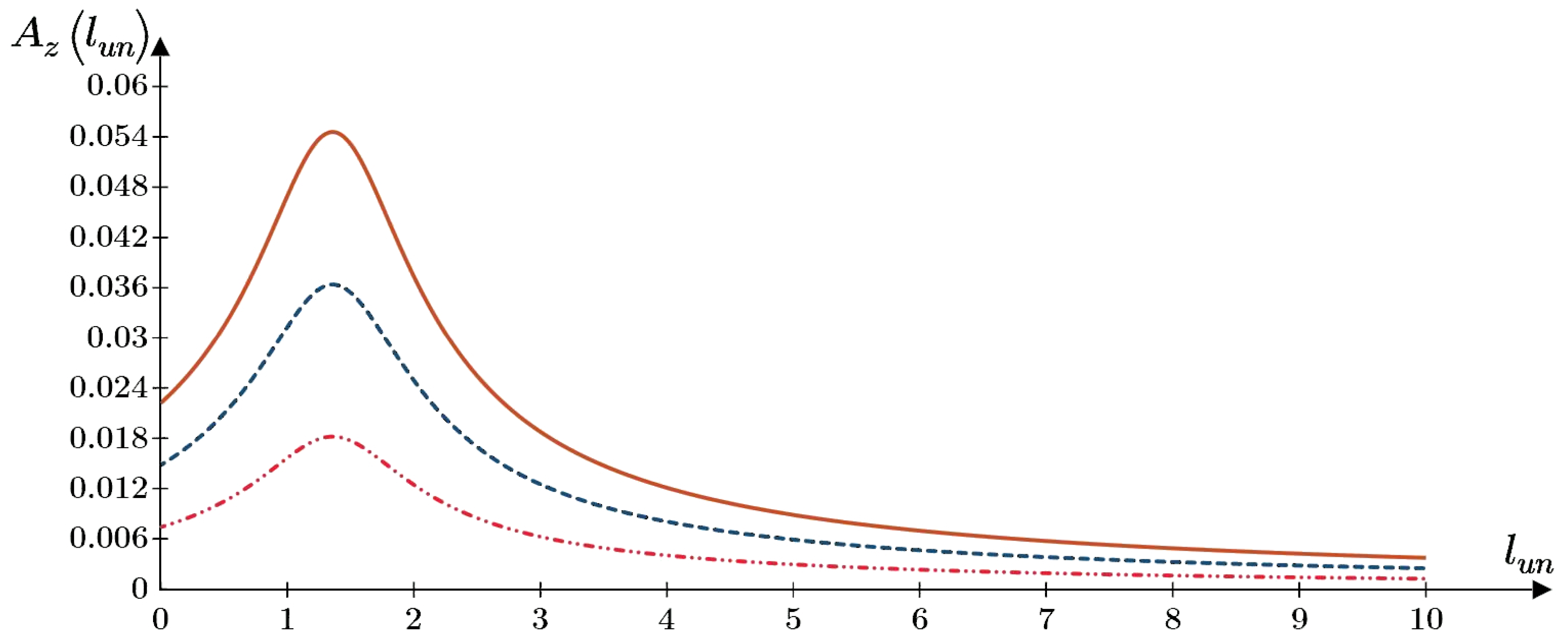
On the whole, the vibration amplitude distribution pattern provided in
Figure 4 is consistent with the analytical solution of Susila E et al. [
22] and the findings of field observations reported by Polunin V.M. [
15,
16,
17,
18].
The above graphs (
Figure 5,
Figure 6,
Figure 7 and
Figure 8) are consistent with the findings of the field studies. Field studies by Preobrazhenskaya N.A. [
12], Lee S.-H. et al. [
27], and Moriyasu S. et al. [
31] also demonstrate a reduction in the pile embedding rate with depth and an increase in the pile embedding rate with an increase in the dynamic component of loading
. Field studies by Preobrazhenskaya N.A. [
12], and Schönit M., Reusch D. [
7] report an increase in the pile embedding rate with an increase in the vibration frequency
ω. The influence of the cross-section size of an embedded element on its embedding rate is also addressed in the field measurements taken by Preobrazhenskaya N.A. [
12], and Qin Z. et al. [
28]. The static embedding load
N is of great importance for the pile embedding rate, as found by O.A. Savinov [
10,
54], and this was also recorded in the field tests by Qin Z. et al. [
28], and Ngoc N.A. et al. [
29].
Figure 9 shows the dependence of the pile embedding depth on time in pile vibrations, obtained by combining elastic pile vibrations (12) with the rate of its viscous embedding (25). The nature of the dependence of the embedding depth on time corresponds to the results of the field studies and numerical simulations provided by Turkel B. et al. [
24]. The scale of
Figure 9a does not allow conveying the feature of this graph. It is not a regular curve, but its shape is sinusoidal (
Figure 9b); i.e., it accumulates the deformation triggered by each vibration cycle, which corresponds to the results of flume tests conducted by Machaček J. et al. [
32] and field observations by Lee S.-H. et al. [
27]. The “variable thickness” of the curve in
Figure 9a indicates a large value of the vibration amplitude at a small depth of the pile embedding and a decrease in the vibration amplitude at a greater depth, which is explained by an increase in the depth-wise resistance and stiffness of the base along the lateral surface of the pile, according to the field studies by Moriyasu S. et al. [
31]. In addition, according to the graphs of the vibration amplitude (see
Figure 5), at a certain depth there occurs “the thickening of the curve”, i.e., an increase in the vibration amplitude due to resonance, as it was observed in the measurements taken by N.A. Preobrazhenskaya [
12], Qin Z. et al. [
28], Moriyasu S. et al. [
31], and Lee S.-H. et al. [
27]. The same section, featuring an increase in the vibration amplitude, is characterized by a steeper slope of the curve, i.e., an increase in the embedding rate, which is explained by a decrease in the coefficient of the viscosity of soil due to an increase in the amplitude of vibrations and vibration acceleration. This aspect also converges with the results of field observations of vibratory piles driven into a sand base [
12].
The vibratory pile driving model proposed by the authors is based on the rheological model of sandy soil under the action of vibration. This model includes a viscosity coefficient, which has not been determined in engineering practice. Despite the absence of information about the viscosity coefficient in other publications on vibratory pile driving, the authors tried to make a comparison with previously conducted experimental studies.
Figure 10 and
Figure 11 show a comparison of the solution obtained using the proposed analytical model with the results of full-scale field experiments by Preobrazhenskaya N.A. [
12] and Moriyasu S. et al. [
31] on the example of a graph of the depth of pile loading with time
z(
n). As can be seen in the graphs, the analytical model of vibratory pile driving shows satisfactory qualitative convergence with the experimental results.
In practice, for the operation of some types of vibratory pile drivers, the task is to keep the pile embedding rate constant, while the value of the static longitudinal load is preset. One can use expression (25) to derive the equation of the static load
N depending on the pile embedding depth
z at the required embedding rate
ϑ (26).
As seen in the above expression (26), the pile vibration acceleration
w0 is a function of
N (to be more precise, it is a function of
pm (12)), and the
N function is not explicit, so this equation can be solved using an iterative process in Mathcad. The expression to be used to find function
N in Mathcad is provided in
Figure 12, where the pile embedding depth is set using iteration
= 0.01 m. The graph showing the dependence between the required static load
N and depth
n at different values of embedding rate
ϑ is shown in
Figure 13 below.
It follows from the analysis of this graph that the required static force N increases linearly with an increase in depth if the embedding rate ϑ remains the same, but if the values of embedding rates are greater, the value of the required static force N increases as well.


 ), ∆N2 = 20 kN (
 ), and ∆N3 = 30 kN (
 ).
).


 ) with the solution according to the proposed analytical model (
 ) for a pile a = 0.1 m, ω = 80 rad/s, ∆N = 21 kN, N = 9 kN, and η0 = 1.5·104 Pa·s.


