Abstract
The Type 2 Fuzzy Logic System (T2FLS) is an enhanced form of the classical Fuzzy Logic System (FLS). The T2FLS based control technics demonstrated a lot of improvements for the past few decades. This is based on the advantage of its membership function (MF). Many experimental studies indicated the superiority of Type 2 Fuzzy Logic Controller (T2FLC) over the ordinary Type 1 Fuzzy Logic Controller (T1FLC), particularly in the event of non-linearities and complex uncertainties. However, the organized design method of T2FLCs is still an interesting problem in the control engineering community. This is due to the difficulties in computing the parameters associated it. A novel application of the Modified Flower Pollination (MFP) optimization algorithm in the design of T2FL is presented. The optimized Cascade Interval Type 2 Fuzzy PID Controller (IT2FPIDC) structure is proposed in this study. The best values of the parameters of the antecedent MFs and the PID gains of IT2FPIDC are found using the MFP algorithm. The MFP optimization technique was used because of its lower computational effort and high convergence speed, in view of the higher number of variables to be optimized in cascaded IT2FPIDC. The MFP-based Type-1 Fuzzy Proportional Integral Derivative Controller (T1FPIDC) is compared with the proposed MFP-based cascade-optimized IT2FPIDC. The rotary inverted pendulum (RIP) which is a non-minimum phase, non-linear, and unstable system is employed as a benchmark for testing the proposed controller. Balance and trajectory-tracking controls of the RIP are considered. Furthermore, the disturbance rejection ability of the proposed controller is analysed. The presented control methos is evaluated on the RIP manufactured by Quanser over many simulations and real-world experiments. The performance characteristics considered are steady state error , settling time , maximum overshoot and rise time . The improvement of the effectiveness and robustness proposed controller in the presence of load disturbance, noise effects and parameter variation is shown.
1. Introduction
Real-world industrial systems show a momentous amount of unpredictability and complexity, making it challenging to design controllers to regulate them [1]. Researchers have proposed multiple controller designs to address these difficulties [2]. In recent decades, contemporary control techniques such as nonlinear, variable structure, adaptive, and optimal methods are employed, but they tend to be complicated and not easily implemented [3,4]. As a result, the control engineering community has become interested in using Type 2 fuzzy logic controllers (T2FLC) for nonlinear systems control, which has shown promising results in various successful applications [5,6]. It is hoped that these strategies will be generalized to other difficult control problems in the future.
There are two kinds of T2FLC: Interval Type-2 Fuzzy Logic Controller (IT2FLC) and General Type-2 Fuzzy Logic Controller (GT2FLC). The former uses Interval Type-2 Fuzzy Sets (IT2FSs) while the later uses wide-ranging Type-2 Fuzzy Sets [7]. This study employs IT2FLC because it is more practical and less computationally complex [8]. Furthermore, IT2FLC can create a very intricate control surface that a T1FLC with the same rule base cannot achieve because of the Footprint of Uncertainty (FOU) advantage inherent in the subsequent membership function of IT2FLC [9]. The construction methodology of the structure of IT2FS can be categorized into two: constructing it from an existing T1FS and directly designing IT2FSs using clustering methods or artificial neural network structures with collected investigational data. Experimental proof suggests that IT2FLC is significantly more efficient and accurate than T1FLC [10,11,12].
The primary challenge in designing IT2FLC is the difficulty and time-consuming nature of computing suitable values of parameter and structure [13]. This challenge has inspired researchers to explore the use of metaheuristics optimization algorithms, like Genetic Algorithm [14], Ant Colony Optimization [15], Big-Bang Big-Crunch Optimization [16], Particle Swarm Optimization [14], Biogeography Optimization [17], Bacterial Foraging Optimization [18], Simulated Annealing [19], Tabu Search Optimization [20], Firefly [21], Bee Colony Optimization [22], Cuckoo search algorithm [23], and hybrid algorithms [24], to automate the design process [23,25]. While these algorithms can provide near-optimal parameter values for IT2FLC, the computation time required is still quite high, and there is no clear consensus on which method is best. A FPA based interval type-2 fuzzy fractional-order controller is presented in [15]. This controller consists of fractional order TID controller and IT2FLC. The proposed controller was tested simulatically on Two nonlinear conical dual-tank level systems. a hybrid traffic signal control system with phase and time optimization based on IT2FLC which was optimized with Crow Search Algorithm and FPA methods, was developed in [25]. A hybrid method for fire outbreak detection based on IT2FL FPA, using environmental parameters is presented in [11]. The proposed controller is experimentally applied to detect a fire outbreak and compared with same controller without optimization which indicates the importance of the optimization technics.
This research proposes a new approach to optimizing the Membership Functions (MFs) structure and scaling factors of the Cascade Interval Type-2 Fuzzy PID Controller (IT2FPIDC) using Modified Flower Pollination (MFP) algorithm. The MFP algorithm was selected because it is both fast and accurate compared to other bio-inspired optimization algorithms [26]. The study employs the use of center-of-set type reduction of Takagi-Sugeno (T-S) type 2 fuzzy systems, which is an effective method for complex nonlinear systems, as mentioned in reference [27]. The design of the IT2FPID controller does not optimize the rule base or resulting MFs; only the PID scaling factors and the preceding MFs elements are optimized. This decision was made to demonstrate the impact of IT2FPIDC’s additional degrees of freedom offered by its FOU.
This research introduces a time domain cost function that integrates four essential performance indicators: settling time, steady-state error, maximum overshoot and rise time. It is verified that employing MFP enhances IT2FPIDCs by searching for an optimal solution, leading to a superior controller when compared to T1FPIDC based on the proposed cost function. Both IT2FPIDC and T1FPIDC adopt a cascade structure, which proves effective for systems experiencing significant timing errors and high noise levels [28]. To validate the IT2FPIDC and T1FPIDC approaches, this study employs the hardware-in-loop (HIL) structure provided by MATLAB’s QUARC target libraries, enabling a real-time controller interface.
The Rotary Inverted Pendulum (RIP) systems perform in an wide range of real life applications, such as flexible systems, locomotive systems, marine systems, mobile systems, pointing control aerospace systems and robotics. In addition, the study of dynamic model and control algorithms in controlling the RIP plays an important role in controlling spacecraft and rockets, maintaining the equilibrium state for two legs robots and skyscraping buildings. Moreover, when the pendulum of RIP is at hanging position, it represents real model of the simplified industry crane application [28]. The RIP is characterized by being non-linear, non-minimum phase, and unstable, making it an ideal system to test the proposed controller experimentally. The RIP has four primary control objectives: stabilization, swing-up, switching, and path tracking controls [29].
This study addressed the stabilization and path tracking controls objectives of the RIP using an MFP based cascade IT2FPIDC. In addition to that, the disturbance rejection capability of the proposed MFP-based cascade IT2FPIDC was analysed. The research began by presenting simulation studies that compared the performance of the optimized IT2FPIDC and optimized T1FPIDC structures. Next, a real experiment was conducted using the Quanser RIP to authenticate the presented cascade control methods. The MFP-based IT2FLC exhibited superior performance compared to the previous techniques in handling parameter variation, load disturbances, and noise effects, as indicated by both simulation and experimental results. Furthermore, it was shown that the path tracking and disturbance rejection achievement of the optimized cascade IT2FPIDC was superior to that of the optimized cascade T1FPIDC in the presence of parameter variations, uncertainties, and noise. These results were confirmed by both simulation and experimental outcomes, which demonstrated the efficacy and robustness of the suggested control methods. The use of MFP as a design strategy was also found to be effective in achieving high-quality solutions with less computing time, which can be advantageous in future applications requiring excellent optimization results in a short period.
The main contributions of the present study concerning the current state of the art and existing papers for optimizing type-2 fuzzy controllers are listed as follows:
- Parameters optimization of the cascade interval type-2 fuzzy logic controller (PID gains of inner and outer controllers, and MFs parameters) using the Modified Flower Pollination (MFP) algorithm is proposed and explained in detail.
- Comparisons of optimized IT2FPIDC and optimized classical T1FPIDC in the presence of parameter variations, uncertainties, and noise are presented. This demonstrates the ability of the proposed controller in handling parameter variation, load disturbances, and noise effects.
- Experimental validations of the simulations are presented.
The rest of the paper is organized as follows. Section 2 describes the Interval Type-2 Fuzzy Logic Systems. Section 3 Presents the Rotary Inverted Pendulum dynamic model and the experimental setup. Section 4 contains a more exhaustive information of Flower pollination algorithm and the modified Flower pollination algorithm. Section 5 contains the explanation of Cascade Control Method including the performance criterion, The internal structure of the Proposed IT2FPIDC and T1FPIDC, the optimization of the T1FPIDC cascade structure using the RIP Algorithm. Section 6 shows the Results and Discussion for both simulation and experiments while Section 7presents the conclusion.
2. Interval Type-2 Fuzzy Logic Systems
This section presents several key characteristics and concepts related to IT2FSs. The concept of fuzzy logic systems and T2FS was originally proposed by Zadeh in 1965 and 1975, respectively. In an IT2FS, all secondary levels are uniform and equal to 1, and are completely determined by the Upper MF (UMF) and Lower MF (LMF) functions [30]. Figure 1 illustrates the construction of an IT2FS when for .
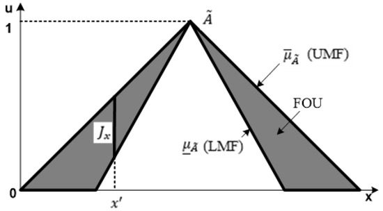
Figure 1.
Illustration of an IT2FS.
A T2FS is characterized by T2-MF , for that is,
In this context, the primary membership is denoted as , while the secondary collection is indicated by , and is a type-1 fuzzy set (T1FS). Consequently, any T2 membership grade must lie within the range of 0 to 1 inclusively [31]. For every primary membership, there exists a corresponding secondary membership that also falls within the range of [1, 0], which characterizes its possibilities. The FOU region is used to represent uncertainty. The generic structure of type-2 fuzzy logic system is shown in Figure 2.

Figure 2.
Structure of Type-2 fuzzy logic system.
2.1. Fuzzification
The purpose of the fuzzifier in type 1 fuzzy and type 2 fuzzy is to transform numeric vector entries into a fuzzy set (type 2 fuzzy set) defined in X. If the input values are singletons, the mapping can be carried out in the following way [32]:
Equation (2) shows that for all .
2.2. Rules
The use of IF-THEN rules is common in both type 1 fuzzy and type 2 fuzzy systems. In type 2 fuzzy systems, the preceding and consequent MFs are depicted using type 2 fuzzy sets. The ith rule in a type 2 fuzzy system can be expressed using Equation (3) [33]:
where is the output of the IF THEN rule, are the following fuzzy sets of type are the preceding fuzzy sets of type −2.
2.3. Inference
In Type 2 fuzzy systems, the deduction mechanism is comparable to Type 1 fuzzy systems. It involves merging rules to create a transformation from an input type 2 fuzzy set to an output type 2 fuzzy set. To accomplish this conversion, it is essential to compute the union, intersection, and composition of type 2 associations [34]. In T2FLS, represents the triggering level of the rule, and it can be expressed as shown in Equation (4).
The productivity of a T2FLS (TSK-type) can be stated as in Equation (5).
If interval T2FSs and T1FSs are used for the antecedents and sequences, respectively, of the type 2 rule, then as well as interval fuzzy sets. Thus,
And
where shows the spread of , and shows the center (mean) of . For IT2FLS, the antecedent rule is an interval T1FS and can be portrayed as:
where
where is a conjunction operator, is a t-norm, which can be an algebraic product or a minimum . The interval value of the consequence can be formulated as follows:
where
2.4. Output Processing
To acquire a precise output, the output processing step includes type reduction which results in a type 1 fuzzy set and defuzzification. The type reduction technique used here is the center-of-set method.
where represents the interval set defined by (two end points); ; ; ; and is the number of rules. Research has demonstrated that IT2FLC defuzzification can be performed as follows [8]:
where are the endpoints of the type-reduced sets. These two endpoints can be calculated by rearranging to set and the equivalent escape interval. The can be considered as follows [31]:
The calculation of the switching points L and R is performed by employing the Karnik-Mendel reduction method.
3. Rotary Inverted Pendulum
Figure 3a,b describe the experimental configuration and schematic diagram of the RIP. Two optical encoders were used to measure the pendulum’s and arm’s angles, and a data collection device was used to gather the encoder information and send it to the computer. Additionally, a data logger was employed to receive control signals from the computer and amplify them through a power amplifier before transmitting them to the motor. This study utilizes the RIP developed by Quanser. The direction of the arm’s movement is considered positive when moving counter clockwise, while the pendulum is considered positive when moving clockwise. The initial angles for the arm and pendulum are 0 and −180 degrees, correspondingly, during real-time testing. The sampling time for the experiments is 0.01 s. The stabilization controller is programmed to activate once the sway angle reaches ±10°.
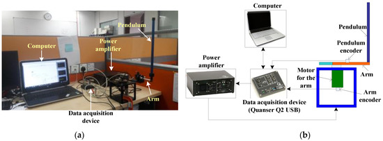
Figure 3.
(a) Experiment setting of RIP, (b) experiment’s schematic diagram of the RIP’s.
The experiments focused on examining the stabilization control and trajectory tracking control of the optimized T1FPIDC and optimized IT2FPIDC controllers. Moreover, the real-time robustness assessment of the proposed optimized controllers was conducted. For this purpose, an extra rod, having identical length and weight as the original pendulum, was affixed to the free end of the pendulum. This modification aimed to modify the physical characteristics of the pendulum by altering the position of its center of mass and diminishing its rigidity. Specifically, the additional rod had a length of 0.1685 m and a weight of 0.0635 kg.
The RIP technology has numerous practical uses in various industries including aerospace, robotics, ships, target control, mobile systems, and locomotive systems [28]. Moreover, the analysis of dynamic models and control methods for RIPs is crucial for controlling rockets and spacecraft, maintaining the balance of biped robots and skyscraper buildings. Additionally, when the pendulum of the RIP is in a hanging position, it can serve as a simplified industrial crane model for industrial applications [35].
Dynamic Model of RIP
To describe the RIP, it can be divided into two components, which are the pendulum part and the arm part. The arm pivot is connected to the motor, and the angle φ increases in a counter clockwise direction about the z-axis. When the control voltage is positive (i.e., ), φ becomes positive. The reference for φ is based on the x-axis. The pendulum is linked to the arm’s free end. As it rotates counter clockwise around an axis that passes through the arm, the pendulum angles ρ and α increase positively. The reference for ρ and α is vertical down and vertical up, respectively. These components are illustrated in Figure 4.
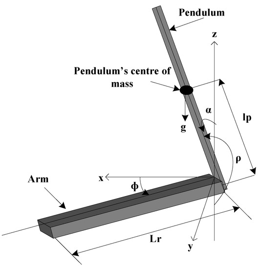
Figure 4.
Mathematical model of RIP.
The state space model (18) and (19) represents the linear dynamics of the RIP. It was achieved by replacing sin(α) with α and cos(α) with 1 in the nonlinear dynamic model, and assigning specific values to the RIP elements, which are listed in Table 1.

Table 1.
Description and values of RIP system.
The RIP system has open loop poles located at w = [0, 9.346, −10.594, −118.272], and it’s evident that the system is unbalanced due to the presence of a pole on the right side of the S-plane. Therefore, before applying any control action, it’s crucial to test the controllability of the system. This is attainable by evaluating the rank of the matrix R using Equation (20). If the rank of R equals 4, then the system is entirely controllable.
4. Flower Pollination Algorithm (FPA) Optimization
The concept of the flower pollination algorithm (FPA) was initially introduced by Yang et al. in 2012 [36,37] and was influenced by the pollination process of flowering plants that occurs in nature. In flowering plants, the flowers play a crucial role in the reproduction process through pollination. Pollination can be categorized as self-pollination, where the flower is fertilized by its own pollen, or cross-pollination, where the pollen from one flower is transferred to another flower belonging to a distinct plant. Cross-pollination typically takes place over considerable distances, and the assistance of pollinators like bees, birds, and flies is essential for facilitating this phenomenon. Bees and birds exhibit flight behavior that adheres to a Levy distribution. Additionally, bloom constancy serves as an incremental step to assess the similarity or dissimilarity between two blooms. The traditional FPA relies on the behavior of flower constancy, where pollinators visit elite flower species while bypassing other flowers. This type of constancy enhances the transfer of pollen to the same flower species, increasing its reproduction. The fundamental principles of the FPA are described as follows:
Rule 1: The process of cross-pollination can be considered as a form of global pollination, where pollinators follow flight patterns that adhere to the Levy distribution.
Rule 2: The procedure of self-pollination can be characterized as local pollination.
Rule 3: Pollinators, such as insects, acquire the ability to persist in flower pollination, which can be equated to a probability of reproduction. This probability is determined by evaluating the resemblance between the two flowers engaged in the process.
Rule 4: The transition from local pollination to global pollination can be controlled by a switching probability, denoted as p, which can take values of either 0 or 1. It is slightly inclined towards favoring local pollination. By incorporating the aforementioned rules, the update equations for FPA (Flowering Persistence Algorithm) can be deduced. The mathematical expression for the first and third rules can be represented as shown in Equation (21).
where represents the pollen or solution at iteration i, is the optimal solution out of all the solutions obtained thus far, is a scaling factor to regulate the step size, and is the Levy-based step size indicating the amount of pollination. Thus as in Equation (22).
where are the typical gamma function and this distribution is satisfactory for large steps . Although is required, in practice is as small as 0.1. However, it is not easy to generate pseudo-random step sizes that correctly follow the Levy distribution [38]. Therefore, an effective algorithm available in the literature, the Mantegna algorithm [39], is used in FPA to arrive at these random values. The step size s can be calculated using two Gaussian distributions and Equation (23):
implies that the samples are drawn from a Gaussian distribution with a mean and variance both set to 0 and , respectively. The variance is obtained with Equation (24)
When the value of x is equal to 1, the gamma functions become and becomes equal to 1. From rules 2 and 3, the update equation for the local pollination can be expressed as in Equation (26):
where and stands for pollen from two various flowers of the same plant. If and are taken mathematically from the same plant species, this distribution becomes a local random walk throughout when drawn from a uniform distribution in [0, 1]. The pollination process of flowers occurs both locally and globally, but in reality, neighbouring flowers are more likely to be pollinated by local pollen than by pollen from a significant distance. This feature can be incorporated into the algorithm by introducing a switching or proximity probability (p) as described in Rule 4. This probability can be used to shift from global pollination to strict local pollination, as required. A value of ρ = 0.5 can be set as the initial probability.
4.1. Modified FPA
The M-FPA method proposes the use of adaptive orientation Gaussian (AOG) mutation to optimize controller parameters. This mutation-based flower pollination process modifies the properties of pollen during pollination to speed up the optimization algorithm. The AOG mutation method is used in FPA to modify certain particle properties and reach the solution faster. The proposed M-FPA algorithm achieves faster convergence while maintaining the traditional FPA’s property consistency. In the conventional FPA, the AOG mutation is applied to global pollination’s produced pollen after the pollination process. As a result, Equation (21) is transformed into Equation (27) following the mutation process [40]:
where is the probability factor. AOG mutation function is given by Equation (27).
where, , , and mean, variance, Gaussian function of the variable and orientation to which the function must be rotated. Likewise, the mutation is applied to p. The one from Equation (25) is modified as Equation (30) after applying the mutation process
The probability factor that determines the likelihood of a change in solution is defined as follows: If the characteristics of pollen obtained from global or local pollination in the current iteration (i + 1) match those obtained in the previous iteration (i), the probability factor is 1. If not, the probability factor is zero, and the solution remains unaffected.
The algorithm for the AOG-FPA is given below [40].
4.2. Implementation of M-FPA for Optimizing IT2FLC Controller
To begin with, a pollen matrix which has the size of n × 4 is taken into account. The controller’s parameters are represented by the pollen, and n indicates the total number of plants. The specific arrangement of the matrix can be found in Equation (32).
Firstly, use the information in each row to calculate the fitness function and identify the plant with the best fitness. The performance criterion from Equation (13) will be used for both the inner and outer controllers. Then, update the pollen for the next iteration by employing either global or local pollination, depending on the switch probability. The pollen for the plant is represented by and has two positions, , where m is 4 for each controller in this particular application. In global pollination, all rows’ pollen is used for pollination, whereas in local pollination, only the same row’s pollen is used because the pollen from a row belongs to the same plant flower. Thus, this algorithm finds the optimal solution set when the convergence criterion is met.
5. Proposed Control Method
The RIP system is a type of SIMO system, meaning that it has multiple outputs controlled by a single input [41]. When one output is affected by disturbances, it can disrupt the control of the other output. Due to the non-linear behavior of the RIP system, determining the elapsed settling time can be difficult. The MFP system also presents challenges, such as a large time constant and elevated noise levels. To address these issues, a cascade control method is recommended. This method is advantageous in reducing the impact of disturbances and improving the dynamics of the entire control loop [42]. By integrating the characteristics of IT2FLC with a cascade control architecture, a stronger and more resilient control response can be attained. Figure 4 illustrates the general structure of the cascade control and the optimization of the controller parameters.
In this particular situation, the system that requires control is made up of two subsystems, referred to as subsystem 1 and subsystem 2, as displayed in Figure 5. The cascade control structure contains two control loops, each with its own controller loop. The discrepancy between the desired input signal and the output of subsystem 2 serves as the input for the outer controller. The input for the inner controller is the disparity between the output of the outer controller 0 and the output of subsystem 1 . The output of the internal regulator serves as a control input for both subsystem 1 and subsystem 2. Tuning the control elements in the cascade control approach can be performed separately, following the process described in the literature [41]. This involves developing the inner loop controller utilizing the suggested objective function first, and then designing the outer controller after tuning the inner controller. This technique is applied in this work. The IT2FPIDC is utilized as both the inner and outer controller in this study. Additionally, the T1FPIDC is utilized as both the inner and outer controller for comparison purposes.

Figure 5.
General cascade control structure with parameters optimization.
5.1. Proposed Performance Criterion
This study implements the optimized IT2FPIDC and T1FPIDC in cascade form and introduces a design method for the MFP-based controller related to the performance criterion C(t) expressed in Equation (33). Optimization methods for T2FLC design typically aim to reduce the integrated absolute error (IAE), integral squared error (ISE), or integrated time-weighted squared error (ITSE), which are commonly utilised performance indices in control system design because of their straightforward assessment in the frequency domain [43]. However, these indices have their benefits and drawbacks. For example, minimizing ISE and IAE can lead to a response with a small overshoot but a long settling time because ISE weighs all errors equally, regardless of when they occur. The ITSE can address this issue, but its analysis formula is complex and time-consuming to derive [43]. To overcome these limitations, this study adopts a time-domain performance criterion that encompasses four different control performance indices:
The performance criterion used in this study includes four performance indices: (steady-state error), (rise time), (settling time), (overshoot), and a weighing factor γ. By adjusting the value of γ, the performance criterion can meet the design requirements. According to Gaing [43], setting γ > 0.7 reduces steady-state error and overshoot, while setting γ < 0.7 reduces settling time and rise time. The study considers two different values of γ (i.e., γ = 1 and 1.5) to analyse the impact of the performance criterion and explore possible solutions.
The performance of the RIP is analyzed in terms of its dynamic behavior and convergence characteristics by studying the average (λ) and variability (σ) of the performance criterion across all subjects in the calculation process. The accuracy of the algorithm is determined using the average value, whereas the speed of convergence of the algorithm is determined using the standard deviation value [44]. The formulas for calculating the variability (σ) and average (λ) are presented in Equations (34) and (35) respectively [45].
where n denotes the population size and denotes the individual performance criterion value.
5.2. Design of T1FPIDC and IT2FPIDC in Cascade Form
In this section, the MFP algorithm-based design of the structures for both T1FPIDC and IT2FPIDC, along with an introduction to their internal structures are portrayed.
5.2.1. The Internal Structure of the Proposed IT2FPIDC and T1FPIDC
Using an MFP algorithm, the methodology optimizes the scaling factor and MFs parameters of the proposed IT2FPIDC for stabilization and path tracking controls objectives of the RIP with negligible stability error. In this situation, the performance of an IT2FPIDC is measured and the result is plot based on the Proposed Performance Criterion. This process is continued to optimize until a stopping criterion or a predefined number of iterations is met. Figure 5 shows a simplified form of the process [46]. The fuzzy system employed in both inner and outer controllers have two inputs and one output. The input parameter is “simulation iterations (SI)” and the output parameter is “change probability (P′)” as adapted from [47,48]. In Equation (36), SI represents the generations of the MFP algorithm. The present simulation denotes the present generations and the maximum number of simulations represents the maximum number of generations. Equation (36) is used to input the trailed IT2FPIDC according to the following method:
After computing the input of tailed type-2 fuzzy inference system the outputs Switching “Probability (P′)” fuzzy FP algorithm can be found. Consequently, after proposing the trilled T2FIS for fuzzy MFP algorithms, the optimized IT2FLS for a RIP control system was realized. The IT2FLC optimized for RIP which is nonlinear systems was tested both with and without uncertainties.
Figure 6 displays the standard fuzzy PID structure with two inputs and one output. The outer controller takes error and error change as its inputs, while its output is denoted as U. These inputs are adjusted to and within the range defined by the outer controller’s input MFs, using the scale factors in that order. To transform the signal into in , output scale factors of are utilized. The process of normalization is based on the equations below:
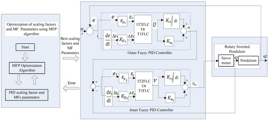
Figure 6.
Standard Fuzzy PID controller in cascade form with parameter optimization.
If the current sampling time is t, the parameter U(t) is the output of the outer control loop and is the sway angle or reference signal.
In a similar fashion, the inner controller takes error and change of error as its inputs, and its output is denoted as V. These inputs are adjusted to E2(t) and ΔE2(t), respectively, by normalization within the domain defined by the inner controller input MFs, using scaling factors . The output is transformed into the control voltage of the servo motor, , through scaling factors . This normalization process is based on the following equations:
where V(t) is the output of the inner loop and is the arm angle.
In Table 2, the technique that employs an unequal rule is utilized for managing both IT2FPIDC and T1FPIDC. Equations (43) and (44) present the usual configuration of IT2FPIDC and T1FPIDC correspondingly.
where is the number of rules, denotes the weighting factor employed to indicate the importance of the respective rule, and . Triangular MFs are employed to describe the entrance of both IT2FLC and T1FLC structures as indicated in Figure 7a,b respectively. These MFs are called negative, zero, and positive, reprents by N, Z, and P respectively. Parameters are used to describe the previous IT2FSs of the IT2PIDC as shown in Figure 7a, where . To be fair in comparisons, the output of IT2FPIDC is the same as that of T1FPIDC (five Singleton Crisp Consequents) as shown in Figure 7c. Also, the weighting factor and the output MFs are not optimized in this study. The weight for all rules is set to 1

Table 2.
Modified Flower Pollination.

Figure 7.
Membership Functions Used.
The proposed optimized IT2FPIDC system utilizes the Matlab/Simulink toolbox for the interval type-2 fuzzy logic system, which has been updated based on the proposal made by Taskin and Kumbasar [49]. This toolbox is employed to initialize the internal configuration of the system.
Correspondingly, three parameters () are employed to describe the T1FSs of the T1FPIDC as shown in Figure 6b Where .
5.2.2. The Optimization of the T1FPIDC Cascade Structure Using the RIP ALGORITHM
In order to minimize the suggested performance measure, the MFP optimization algorithms are employed to optimize the parameters of the preceding MFs and the scale factors for both inner and outer controllers. Table 3 shows the three parameters for each input that define the three antecedent MFs of T1FLC (N, Z, and P).
where . For the T1FPIDC two-input design, the previous MF has a total of 18 structural parameters that need to be optimized, since each input has 9 parameters. Additionally, four scale factors for both the input and output of the T1FPIDC must also be optimized. Therefore, a collection of 22 factors must be optimized using MFP to minimize the performance criterion. The inner loop’s optimization variables are defined as follows:

Table 3.
Rule base of T1FLC and IT2FLC with weights.
The same variables that are used in the inner loop are also optimized using MFP in the outer loop. The optimization process for the T1FPIDC is divided into two stages. In the first stage, MFP is used to optimize the inner loop controller parameters guided by the reference trajectory generated by the outer loop controller. In the second stage, the outer loop controller parameters are optimized using MFP, considering the desired reference trajectory specified by the designer, and the parameters of the inner controller are determined accordingly. Both stages aim at minimizing the performance criterion. The parameters of the preceding MFs of both the outer and inner control loops are optimized in order to have normal convex T1FSs, according to the constraints provided by the following equations:
5.2.3. The Optimization of IT2FPIDC Cascade Structure Using Meta-Heuristic Optimization Algorithms
To reduce the specified performance criterion, the MFP is employed to optimize the scale factors and parameters of the preceding MFs for both inner and outer controllers of IT2FPIDC. Each input of the three previous MFs of IT2FPIDLC (N, Z, and P) is defined with five parameters. These parameters are:
where . For the IT2FPIDC two-input design, the legacy MF has a total of 30 parameters that need to be optimized, since each input has 15 parameters. This is more than the 18 structure parameters of the T1FPIDC, meaning that the IT2FPIDC has an additional design degree of freedom compared to the T1FPIDC. As with the T1FPIDC, the IT2FPIDC also consists of four scaling factors for both input and output that require optimization. Therefore, a total of 34 parameters need to be optimized using MFP to minimize the performance criterion. Unlike T1FPIDC, the rule base and resulting MFs are not optimized in the IT2FPID controller design, as the goal is to demonstrate the efficiency of the additional DOF of IT2FSs produced by the FOU in IT2FSs in a closed-loop system performance. Therefore, the optimization variables for MFP are defined as:
The same variables as for the inner control loop are also subject to optimization for the outer control loop. Furthermore, the weighting element is considered as 1 for all rules, just similar to T1FPIDC, and is not optimized. The optimization process for IT2FPIDC follows similar approach as described for T1FPIDC. In order to achieve normal convex IT2FSs, the parameters of the preceding outer and inner loop MFs are optimized according to the limitations specified in the subsequent equations:
The pseudo codes for MFP methods guided by IT2PIDC and T1FPIDC are given in Table 3.
5.2.4. Configuration Values for Optimization Algorithms
This research used specific values for three parameters—the number of nests, the step size scaling factor, and the switching attribute—which were selected through rigorous experimentation. The authors of the study explain that in a system with multiple solutions, the nests (i.e., potential solutions) are located at different local optima. Therefore, if there are more nests than local optima, the algorithm used in the study can find all of the optima at the same time. This is particularly important for multi-objective and multi-modal optimization problems, which are the focus of this research. The MFP algorithm was implemented in Matlab and tested in 60 different runs with different initial test solutions. The simulations were carried out using Matlab R2013a on a 2.4 GHz processor with 8 GB RAM. The authors also provide a Simulink diagram for implementing the optimized controllers in cascade form, which applies to both T1FPIDC and IT2FPID. The initial angles for the arm and pendulum in the simulations were 0 and 0.97 degrees, respectively.
6. Results and Discussion
This section contains the simulations and test outcomes, including the optimized antecedent membership functions and the optimal scaling factor values for both optimized T1FPIDC and optimized IT2FPIDC. The convergence properties of the proposed optimization algorithms are also discussed. Furthermore, the results include the analysis of stabilization control, trajectory tracking control, disturbance rejection, and validation of the simulation results against the real-time results.
6.1. Simulation Results
The optimization of the inner and outer controllers aimed to reduce the suggested cost function. Figure 8 and Figure 10 display the optimized antecedent membership functions for the inner loop , as well as the outer loop , for T1FPIDC and IT2FPIDC using the MFP algorithm. The weighting factor γ was set to 1 for these optimizations. Meanwhile, Figure 9 and Figure 11 show the optimized antecedent membership functions for the inner loop , as well as the outer loop , for T1FPIDC and IT2FPIDC using the MFP algorithm with a weighting factor of γ = 1.5.
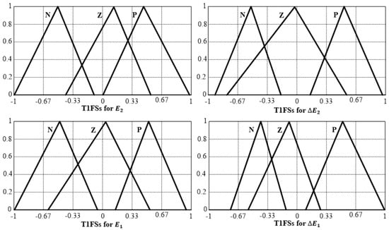
Figure 8.
Optimized antecedent MFs of T1FPIDC (MFP-based), .
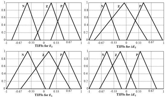
Figure 9.
Optimized antecedent MFs of T1FPIDC (MFP-based), .
To reduce the suggested cost function, the inner and outer controllers were optimized. The optimized antecedent membership functions (MFs) for the inner loop and outer loop of T1FPIDC and IT2FPIDC, using the MFP algorithm, were presented in Figure 8 and Figure 10, respectively, by setting the weighting factor γ = 1. Similarly, Figure 9 and Figure 11 show the optimized antecedent MFs for the inner loop of T1FPIDC and IT2FPIDC, as well as the outer loop , using the MFP algorithm with γ = 1.5.
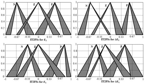
Figure 10.
Optimized antecedent MFs of IT2FPIDC (MFP-based), .
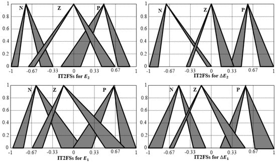
Figure 11.
Optimized antecedent MFs of IT2FPIDC (MFP-based), .
6.1.1. Convergence Characteristics Based on T1FPIC
Two statistical simulations were conducted to evaluate the convergence properties of the proposed T1FPIDC. The acquisition value’s standard deviation and mean were used as indicators of speed and accuracy, respectively. Results presented in Figure 12a,b indicate that both MFP-based IT2FPIDC and FP-based T1FPIDC maintain a stable average cost value for weighting factors γ = 1 and γ = 1.5 under the same simulation conditions and performance criteria. However, MFP-based IT2FPIDC controllers outperformed MFP-based T1FPIDC in terms of mean and cost value, demonstrating better accuracy for both γ = 1 and γ = 1.5.

Figure 12.
Tendency of convergence of mean value of performance criterion with The optimized scaling factors for the optimized cascade IT2FPIDC and optimized cascade T1FPIDC are shown in Table 4.

Table 4.
Optimized scaling factors for cascade IT2FPIDC and T1FPIDC.
Table 5 displays the optimal runtime for T1FPIDCs and IT2FPIDCs after 100 iterations. The results reveal that IT2FPID has a longer runtime than T1FPIDC for each optimization algorithm, which is attributed to the greater number of optimization parameters in IT2FPIDC than T1FPIDC.

Table 5.
Average computational time for IT2FPIDCs and T1FPIDCs.
6.1.2. Stabilization Control Using Optimized Cascade IT2FPIDC
This section presents an analysis of the stabilization control of RIP using two optimized cascade controllers, namely IT2FPIDC and T1FPIDC. The designated swing angle was established as zero, which is considered to be the unstable upright position. Figure 13 displays the best results obtained for various parameters, such as pendulum angle, arm angle, outer loop output, and inner loop output for a specific value of γ = 1. To assess the impact of changing the value of γ, it was increased to 1.5, and the corresponding results are presented in Figure 14. The simulation results for 60 runs with different values of γ are summarized in Table 6. Based on the results presented in Table 6, it can be concluded that the optimized cascade IT2FPIDC designed using the MFP method outperforms the optimized IT2FPIDC designed using GA and PSO proposed in [14] in various performance indices, such as rise time , settling time (less than 2%), steady-state error , and maximum overshoot .
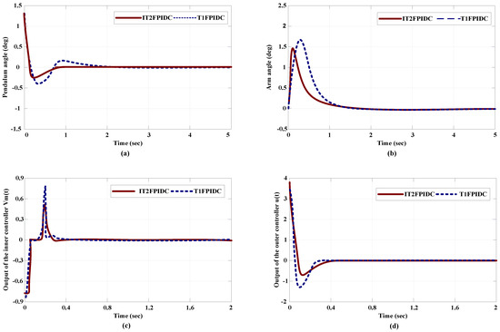
Figure 13.
Comparative simulation results for the MFP-based cascade IT2FPIDC and the MFP basic cascade T1FPIDC with , (a) pendulum angle, (b) arm angle, (c) Outer loop output (d) Inner loop output.
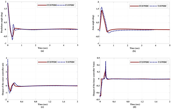
Figure 14.
Comparativesimulation results for theMFP-based cascade IT2FPIDC and the MFP-base cascade T1FPIDC with , (a) pendulum angle, (b) arm angle, (c) Outer loop output (d) Inner loop output.

Table 6.
Comparative simulation analysis results for optimized cascade IT2FPIDC and optimized cascade T1FPIDC.
6.1.3. Disturbances Rejection Analysis in Stabilization Control for MFP-Based Cascade IT2FPIDC and T1FPIDC
To test the durability of the proposed IT2FPIDC/T1FPIDC optimized cascade, both internal and external disruptions are incorporated into the RIP system. A load with a length of 0.1965 m and a mass of 0.0741 kg is also added to the pendulum. Moreover, the output of the procedure (feedback) is subjected to random noise of 0.00739 power and 10% parameter value alterations, as depicted in Figure 15. The sway angle, arm angle, outer loop output, and inner loop output under disruptive circumstances are illustrated in Figure 16, demonstrating the effectiveness and resilience of the IT2FPIDC. Although there are instances of oscillations in the arm and pendulum angles, ranging from −0.1 to 0.2 degrees and −0.04 to 0.04 degrees, respectively, which are absent in the disturbance-free simulation, all controllers successfully manage to swing the pendulum into an upright position and stabilize it in an unstable state with minimal vibration. Table 7 displays the controller’s performance in the event of faults, clearly indicating the superiority of IT2FPIDC over T1FPIDC in the presence of interference.

Figure 15.
MFP-based Cascade IT2FPIDC/T1FPIDC including the source of noise.
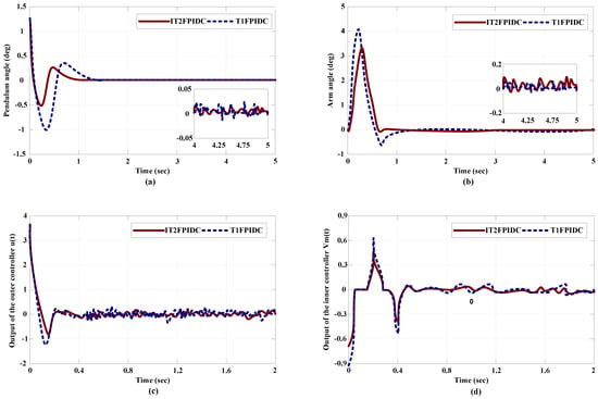
Figure 16.
Comparativesimulation results for disturbance rejection ability of MFP-base cascade IT2FPIDC and MFP-base cascade T1FPIDC. (a) pendulum angle, (b) arm angle, (c) Outer loop output (d) Inner loop output.

Table 7.
Comparative simulation analysis results for disturbance rejection ability of optimized cascade IT2FPIDC and optimized cascade T1FPIDC.
6.1.4. Trajectory Tracking Control for Optimized Cascade T1FPIDC
One of the key aims of RIP control is to manage the trajectory, which indicates how well the controller can guide the RIP arm to follow a specific time-dependent path while the pendulum remains in an unstable state. Achieving this objective involves creating a controller that can keep both the trajectory error and the sway angle within certain limits [50]. The controller design should ensure that these limits remain uniform over time. The designed controller guarantees the following:
were are constant, and . In this research, the intended path function utilized is a time-dependent square function. This function is both smooth and has a derivative. Furthermore, are constrained for all . The output function is defined as:
A thorough description and development of RIP trajectory tracking control can be located in [51,52].
Figure 17 illustrates the optimal simulation outcomes of RIP trajectory tracking control for the optimized cascade IT2FPIDC/T1FPIDC at γ = 1 for arm and weave angles in Figure 17a,c, respectively. Furthermore, the simulation result for the RIP trajectory tracking control using the optimized cascade IT2FPIDC/T1FPIDC at γ = 1.5 is shown in Figure 17b,d for arm and weave angles, respectively. Observing both Figure 17a,b, it is evident that the MFP-based cascade IT2FPIDC achieves the target value rapidly in comparison to the MFP-based cascade T1FPIDC. The detailed performance comparison is presented in Table 8.
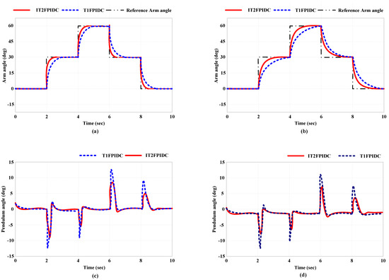
Figure 17.
Trajectory tracking control by optimized cascade IT2FPIDC/T1FPIDC. (a) pendulum angle, (b) arm angle, (c) Outer loop output (d) Inner loop output.

Table 8.
Comparative trajectory tracking results for optimized cascade T1FPIDC (Simulation).
6.2. Experimental Validation
This section presents experimental outcomes that validate the simulation findings. These outcomes comprise of stabilization control, trajectory tracking control, and clutter rejection analysis, all of which were obtained at γ = 1 for both MFP-based IT2FPIDC and MFP-based T1FPIDC. The reason for choosing the MFP-based controllers and weighting factor γ = 1 for validation is because they exhibited superior action compared to other controllers in the simulation studies.
6.2.1. Stabilization Control (Experiments)
Figure 18a,b depicts the experimental results in the real world, comparing the proposed MFP-based optimized cascade IT2FPIDC, the MFP-based optimized cascade T1FPIDC, and a traditional energy-based controller for pendulum and arm angles, where the equilibrium state is to be established. The actual results obtained from the physical system indicate initial oscillations, which arise due to the required swinging motion needed to position the pendulum in a vertically unstable state. The two controllers, MFP-based optimized cascade IT2FPIDC and MFP-based optimized cascade T1FPIDC, demonstrate a notable level of resilience. However, the conventional energy-based controller exhibits multiple oscillations before achieving stability. The conventional energy-based controllers also require more time to reach a steady state compared to MFP-based optimized cascade IT2FPIDC and MFP-based optimized cascade T1FPIDC. Furthermore, MFP-based optimized IT2FPIDC achieves steady state faster than the optimized cascade T1FPIDC.
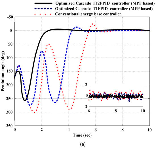
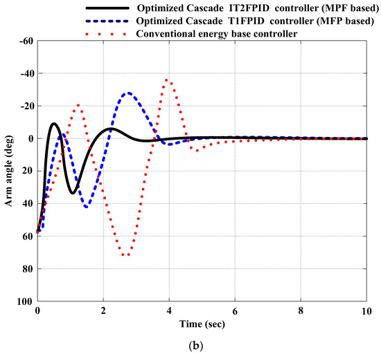
Figure 18.
Experimental results for stabilization control.
6.2.2. Trajectory Tracking Control (Experiments)
A reference signal in the form of a square wave with an amplitude of ±40° is utilized to guide the arm’s movement. Figure 19a,b depict the reaction of the arm angle and pendulum angle, respectively. The optimized cascade MFPs based on IT2FPIDC and T1FPIDC exhibit a smooth ability to direct the motor shaft to follow the desired trajectories while also maintaining the pendulum’s upright stance (approximately 0). Moreover, the systems are capable of continuously compensating for any mechanical disturbances, such as friction.
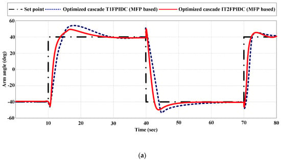
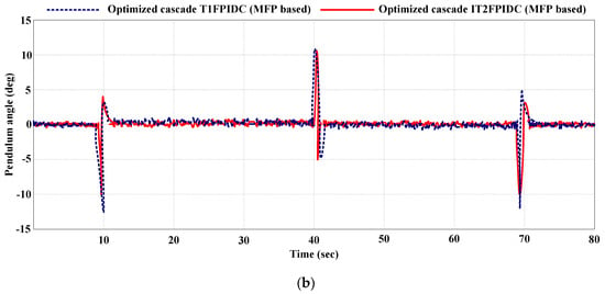
Figure 19.
Experimental result for trajectory tracking control (comparing optimized cascade MFP-based IT2FPIDC and T1FPIDC).
6.2.3. Disturbance Rejection Analysis (Experiments)
To test the resilience of the proposed cascade-optimized MFP-based IT2FPIDC and T1FPIDC controllers, internal noise and external disturbances were introduced to the system in real-world experiments. A pendulum load with a length of 0.1685 m and a mass of 0.0635 kg was added, and the process output (feedback) was subjected to random noise with a power of 0.00634 and 10% parameter value changes. Figure 20a,b display the empirical findings pertaining to the trajectory control of the RIP system with the arm and pendulum angles. The experimental and simulation outcomes showed that the optimized cascade IT2FPIDC outperformed the optimized cascade T1FPIDC in terms of load disturbances, parameter variations, and noise effects. Although there were slight variations in the arm and pendulum angles compared to the experimental results without perturbations, both controllers effectively directed the movement of the motor shaft to track the intended paths while simultaneously stabilizing the pendulum in an upright stance (around 0) and compensating for mechanical and introduced disturbances with minimal vibrations. Grounded on the experimental outcomes, it can be inferred that the optimized cascade IT2FPIDC improved the performance of the cascade-optimized T1FPIDC and the conventional energy-based controller on the RIP. Table 9 demonstrates the superior performance of the optimized cascade IT2FPIDC over the optimized cascade T1FPIDC in the presence of faults without a faulted state.
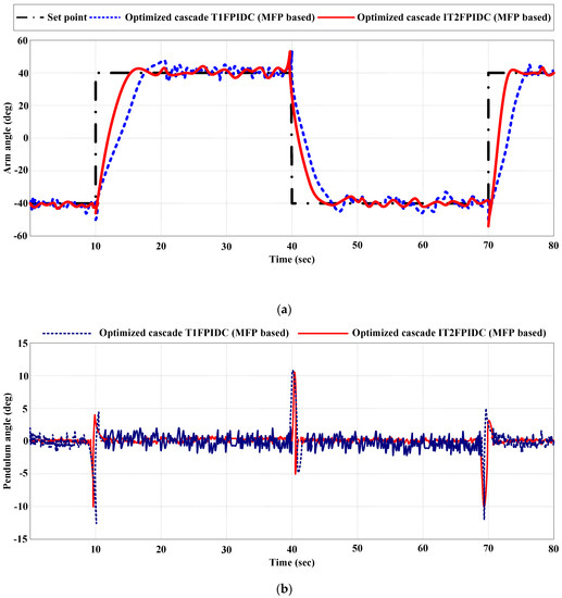
Figure 20.
Experimental result for disturbed trajectory tracking control (comparing optimized cascade MFP-based IT2FPIDC and T1FPIDC).

Table 9.
Comparative trajectory tracking results for optimized cascade MFP-based IT2FPIDC and T1FPIDC (Experiment).
7. Conclusions
The main goal of this study is to explore the potential benefits of utilizing the MFP algorithm approach to design IT2FPIDC and to examine the merits of IT2FLC over T1FLC. The study compares the optimization performances of IT2FPIDC in a cascade structure with those of T1FPIDC in a cascade structure. The comparison is based on four performance measures: steady-state error (Ess), settling time (ts), rise time (tr), and maximum overshoot (Mp).
The results of the study indicate that using the MFP-based design approach can produce high-quality solutions with a significantly reduced computing time of 196.33 min. Consequently, this approach can be used for designing more intricate IT2FLCs with an increased number of input/output parameter applications, requiring optimized results in a shorter time frame. To demonstrate the benefits of using FOU in IT2FPIDC, the study kept the rule-based, rule-weighted elements, and the resulting MFs factors fixed.
The study only optimized the scaling factors and the parameters of the preceding MFs parameters, and this approach was also applied to the T1FPIDC for an equitable comparison. The main limitation of the present study is limited number of MFs used and the time taken for the multi-objective optimization cost function. The experimental and simulation outcomes indicated that the optimized cascade IT2FPIDC outperformed the optimized cascade T1FPIDC in terms of the four performance measures (, , , and ) regardless of the optimization method used.
For instance, the optimized cascade IT2FPIDC exhibited a progress between 6.1% to 33.3%, 5.7% to 35.2%, and 6.6% to 20.8% in ,, and , in the corresponding order, when compared to its T1FPIDC counterpart in the presence of disturbances. This is possibly a result of FOU present in IT2FPIDC, that enables it to handle complex systems which T1FPIDC cannot control with the same set of rules.
In the future, a more complex benchmark will be used to test the proposed controller. Also, optimization of general type-2 fuzzy logic controller (GT2FLC) using MFP should be tested. This will enable us to compare the performance of T1FLC, IT2FLC, and GTFLC.
Funding
This study is supported via funding from Prince Sattam bin Abdulaziz University project number (PSAU/2023/R/1444).
Data Availability Statement
Not applicable.
Conflicts of Interest
The author declares no conflict of interest.
References
- Rigatos, G.G. Modelling and control for intelligent industrial systems. In Adaptive Algorithms in Robotics and Industrial Engineering; Springer: New York, NY, USA, 2011. [Google Scholar]
- Hamza, M.F.; Yap, H.J.; Choudhury, I.A. Recent advances on the use of meta-heuristic optimization algorithms to optimize the type-2 fuzzy logic systems in intelligent control. Neural Comput. Appl. 2015, 28, 979–999. [Google Scholar] [CrossRef]
- Zhang, Y.; Li, S.; Liao, L. Near-optimal control of nonlinear dynamical systems: A brief survey. Annu. Rev. Control. 2019, 47, 71–80. [Google Scholar] [CrossRef]
- Liu, D.; Xue, S.; Zhao, B.; Luo, B.; Wei, Q. Adaptive Dynamic Programming for Control: A Survey and Recent Advances. IEEE Trans. Syst. Man, Cybern. Syst. 2020, 51, 142–160. [Google Scholar] [CrossRef]
- Mittal, K.; Jain, A.; Vaisla, K.S.; Castillo, O.; Kacprzyk, J. A comprehensive review on type 2 fuzzy logic applications: Past, present and future. Eng. Appl. Artif. Intell. 2020, 95, 103916. [Google Scholar] [CrossRef]
- Cervantes, L.; Caraveo, C.; Castillo, O. Performance Comparison between Type-1 and Type-2 Fuzzy Logic Control Applied to Insulin Pump Injection in Real Time for Patients with Diabetes. Mathematics 2023, 11, 730. [Google Scholar] [CrossRef]
- Mendel, J.M. General Type-2 Fuzzy Logic Systems Made Simple: A Tutorial. IEEE Trans. Fuzzy Syst. 2013, 22, 1162–1182. [Google Scholar] [CrossRef]
- Liang, Q.; Mendel, J. Interval type-2 fuzzy logic systems: Theory and design. IEEE Trans. Fuzzy Syst. 2000, 8, 535–550. [Google Scholar] [CrossRef]
- Mendel, J.M.; John, R.I.; Liu, F. Interval Type-2 Fuzzy Logic Systems Made Simple. IEEE Trans. Fuzzy Syst. 2006, 14, 808–821. [Google Scholar] [CrossRef]
- Castillo, O.; Amador-Angulo, L.; Castro, J.R.; Garcia-Valdez, M. A comparative study of type-1 fuzzy logic systems, interval type-2 fuzzy logic systems and generalized type-2 fuzzy logic systems in control problems. Inf. Sci. 2016, 354, 257–274. [Google Scholar] [CrossRef]
- Montazeri-Gh, M.; Yazdani, S. Application of interval type-2 fuzzy logic systems to gas turbine fault diagnosis. Appl. Soft Comput. 2020, 96, 106703. [Google Scholar] [CrossRef]
- Ochoa, P.; Castillo, O.; Soria, J. Optimization of fuzzy controller design using a Differential Evolution algorithm with dynamic parameter adaptation based on Type-1 and Interval Type-2 fuzzy systems. Soft Comput. 2020, 24, 193–214. [Google Scholar] [CrossRef]
- Valdez, F.; Castillo, O.; Cortes-Antonio, P.; Melin, P. A survey of Type-2 fuzzy logic controller design using nature inspired optimization. J. Intell. Fuzzy Syst. 2020, 39, 6169–6179. [Google Scholar] [CrossRef]
- Hamza, M.F.; Yap, H.J.; Choudhury, I.A. Genetic Algorithm and Particle Swarm Optimization Based Cascade Interval Type 2 Fuzzy PD Controller for Rotary Inverted Pendulum System. Math. Probl. Eng. 2015, 2015, 695965. [Google Scholar] [CrossRef]
- Zhang, Z.; Wang, T.; Chen, Y.; Lan, J. Design of type-2 Fuzzy Logic Systems Based on Improved Ant Colony Optimization. Int. J. Control. Autom. Syst. 2019, 17, 536–544. [Google Scholar] [CrossRef]
- Leon-Garza, H.; Hagras, H.; Pena-Rios, A.; Conway, A.; Owusu, G. A big bang-big crunch type-2 fuzzy logic system for explainable semantic segmentation of trees in satellite images using hsv color space. In Proceedings of the 2020 IEEE International Conference on Fuzzy Systems (FUZZ-IEEE), Glasgow, UK, 19–24 July 2020; IEEE: New York, NY, USA, 2020. [Google Scholar]
- Mohammadikia, R.; Aliasghary, M. Design of an interval type-2 fractional order fuzzy controller for a tractor active suspension system. Comput. Electron. Agric. 2019, 167, 105049. [Google Scholar] [CrossRef]
- Kiani, M.; Mohammadi, S.M.A.; Gharaveisi, A.A. A bacterial foraging optimization approach for tuning type-2 fuzzy logic controller. Turk. J. Electr. Eng. Comput. Sci. 2013, 21, 263–273. [Google Scholar] [CrossRef]
- Türk, S.; Deveci, M.; Özcan, E.; Canıtez, F.; John, R. Interval type-2 fuzzy sets improved by Simulated Annealing for locating the electric charging stations. Inf. Sci. 2021, 547, 641–666. [Google Scholar] [CrossRef]
- Almaraashi, M.; Hedar, A.-R. Optimization of interval type-2 fuzzy logic systems using tabu search algorithms. In Proceedings of the 2014 Sixth World Congress on Nature and Biologically Inspired Computing (NaBIC 2014), Porto, Portugal, 30 July–1 August 2014; IEEE: New York, NY, USA, 2014. [Google Scholar]
- Ray, P.K.; Paital, S.R.; Mohanty, A.; Foo, Y.S.E.; Krishnan, A.; Gooi, H.B.; Amaratunga, G.A.J. A Hybrid Firefly-Swarm Optimized Fractional Order Interval Type-2 Fuzzy PID-PSS for Transient Stability Improvement. IEEE Trans. Ind. Appl. 2019, 55, 6486–6498. [Google Scholar] [CrossRef]
- Amador-Angulo, L.; Castillo, O. A new fuzzy bee colony optimization with dynamic adaptation of parameters using interval type-2 fuzzy logic for tuning fuzzy controllers. Soft Comput. 2016, 22, 571–594. [Google Scholar] [CrossRef]
- Hamza, M.F.; Yap, H.J.; Choudhury, I.A. Cuckoo search algorithm based design of interval Type-2 Fuzzy PID Controller for Furuta pendulum system. Eng. Appl. Artif. Intell. 2017, 62, 134–151. [Google Scholar] [CrossRef]
- De (Maity), R.R.; Mudi, R.K.; Dey, C. Nature-inspired and hybrid optimization algorithms on interval Type-2 fuzzy controller for servo processes: A comparative performance study. SN Appl. Sci. 2020, 2, 1292. [Google Scholar]
- Kumar, A.; Kumar, V. Performance analysis of optimal hybrid novel interval type-2 fractional order fuzzy logic controllers for fractional order systems. Expert Syst. Appl. 2018, 93, 435–455. [Google Scholar] [CrossRef]
- Chiroma, H.; Shuib, N.L.M.; Muaz, S.A.; Abubakar, A.I.; Ila, L.B.; Maitama, J.Z. A Review of the Applications of Bio-inspired Flower Pollination Algorithm. Procedia Comput. Sci. 2015, 62, 435–441. [Google Scholar] [CrossRef]
- Wu, D.; Mendel, J.M. Recommendations on designing practical interval type-2 fuzzy systems. Eng. Appl. Artif. Intell. 2019, 85, 182–193. [Google Scholar] [CrossRef]
- Hamza, M.F.; Yap, H.J.; Choudhury, I.A.; Isa, A.I.; Zimit, A.Y.; Kumbasar, T. Current development on using Rotary Inverted Pendulum as a benchmark for testing linear and nonlinear control algorithms. Mech. Syst. Signal Process. 2019, 116, 347–369. [Google Scholar] [CrossRef]
- Nguyen, N.P.; Oh, H.; Kim, Y.; Moon, J. A nonlinear hybrid controller for swinging-up and stabilizing the rotary inverted pendulum. Nonlinear Dyn. 2021, 104, 1117–1137. [Google Scholar] [CrossRef]
- Khanesar, M.A.; Kaynak, O. Recurrent interval type-2 neuro-fuzzy control of an electro hydraulic servo system. In Proceedings of the 2016 IEEE 14th International Workshop on Advanced Motion Control (AMC), Auckland, New Zealand, 22–24 April 2016; IEEE: New York, NY, USA, 2016. [Google Scholar]
- Karnik, N.N.; Mendel, J.M. Introduction to type-2 fuzzy logic systems. In Proceedings of the 1998 IEEE International Conference on Fuzzy Systems Proceedings. IEEE world Congress on Computational Intelligence (Cat. No. 98CH36228), Anchorage, AK, USA, 4–9 May 1998; IEEE: New York, NY, USA, 1998. [Google Scholar]
- Mendel, J.M. Advances in type-2 fuzzy sets and systems. Inf. Sci. 2007, 177, 84–110. [Google Scholar] [CrossRef]
- Mendel, J.; Hagras, H.; Tan, W.W.; Melek, W.W.; Ying, H. Introduction to Type-2 Fuzzy Logic Control: Theory and Applications; John Wiley & Sons: New York, NY, USA, 2014. [Google Scholar]
- Tan, W.W.; Chua, T.W. Uncertain Rule-Based Fuzzy Logic Systems: Introduction and New Directions (Mendel, J.M.; 2001) [book review]. IEEE Comput. Intell. Mag. 2007, 2, 72–73. [Google Scholar] [CrossRef]
- Hamza, M.F.; Yap, H.J.; Choudhury, I.A.; Isa, A.I. Application of Kane’s Method for Dynamic Modeling of Rotary Inverted Pendulum System. In Proceedings of the 2016 MNTMSim Conference, Kuala Lumpur, Malaysia, 1–3 March 2016. [Google Scholar]
- Yang, X.-S. Flower pollination algorithm for global optimization. In Proceedings of the Unconventional Computation and Natural Computation: 11th International Conference, UCNC 2012, Orléan, France, 3–7 September 2012; Springer: New York, NY, USA, 2012. [Google Scholar]
- Yang, X.-S.; Karamanoglu, M.; He, X. Flower pollination algorithm: A novel approach for multiobjective optimization. Eng. Optim. 2014, 46, 1222–1237. [Google Scholar] [CrossRef]
- Pavlyukevich, I. Lévy flights, non-local search and simulated annealing. J. Comput. Phys. 2007, 226, 1830–1844. [Google Scholar] [CrossRef]
- Mantegna, R.N. Fast, accurate algorithm for numerical simulation of Lévy stable stochastic processes. Phys. Rev. E 1994, 49, 4677–4683. [Google Scholar] [CrossRef] [PubMed]
- Rajeswari, C.; Santhi, M. Modified flower pollination algorithm for optimizing FOPID controller and its application with the programmable n-level inverter using fuzzy logic. Soft Comput. 2021, 25, 2615–2633. [Google Scholar] [CrossRef]
- Kumar, R.; Sikander, A. A novel load frequency control of multi area non-reheated thermal power plant using fuzzy PID cascade controller. Sādhanā 2023, 48, 25. [Google Scholar]
- Campos-Rodríguez, A.; García-Sandoval, J.; González-Álvarez, V. Hybrid cascade control for a class of nonlinear dynamical systems. J. Process. Control. 2019, 76, 141–154. [Google Scholar] [CrossRef]
- Gaing, Z.-L. A Particle Swarm Optimization Approach for Optimum Design of PID Controller in AVR System. IEEE Trans. Energy Convers. 2004, 19, 384–391. [Google Scholar] [CrossRef]
- Hassanzadeh, I.; Mobayen, S. Controller Design for Rotary Inverted Pendulum System Using Evolutionary Algorithms. Math. Probl. Eng. 2011, 2011, 572424. [Google Scholar] [CrossRef]
- Haupt, R.L.; Haupt, S.E. Practical Genetic Algorithms; John Wiley & Sons: New York, NY, USA, 2014. [Google Scholar]
- Korkmaz, E.; Akgungor, A.P. A Hybrid Traffic Controller System based on Flower Pollination Algorithm and Type-2 Fuzzy Logic Optimized with Crow Search Algorithm for Signalized Intersections. Res. Sq. 2022. [Google Scholar] [CrossRef]
- Umoh, U.A.; Inyang, U.G.; Nyoho, E.E. Soft Computing for Problem Solving 2019: Proceedings of SocProS. In 2019A Hybrid Framework for Fire Outbreak Detection Based on Interval Type-2 Fuzzy Logic and Flower Pollination Algorithm; Springer: Singapore, 2020; Volume 2, pp. 27–45. [Google Scholar]
- Patel, H.R.; Shah, V.A. Shadowed Type-2 Fuzzy Sets in Dynamic Parameter Adaption in Cuckoo Search and Flower Pollination Algorithms for Optimal Design of Fuzzy Fault-Tolerant Controllers. Math. Comput. Appl. 2022, 27, 89. [Google Scholar] [CrossRef]
- Taskin, A.; Kumbasar, T. An open source Matlab/Simulink toolbox for interval type-2 fuzzy logic systems. In Proceedings of the 2015 IEEE Symposium Series on Computational Intelligence, Cape Town, South Africa, 7–10 December 2015; IEEE: New York, NY, USA, 2015. [Google Scholar]
- Khalil, H.K.; Grizzle, J. Nonlinear Systems; Prentice Hall: Hoboken, NJ, USA, 1996; Volume 3. [Google Scholar]
- Aguilar-Avelar, C.; Moreno-Valenzuela, J. A composite controller for trajectory tracking applied to the Furuta pendulum. ISA Trans. 2015, 57, 286–294. [Google Scholar] [CrossRef]
- Patel, H.R.; Shah, V.A. A metaheuristic approach for interval type-2 fuzzy fractional order fault-tolerant controller for a class of uncertain nonlinear system. Automatika Časopis za automatiku, mjerenje, elektroniku, računarstvo i komunikacije 2022, 63, 656–675. [Google Scholar] [CrossRef]
Disclaimer/Publisher’s Note: The statements, opinions and data contained in all publications are solely those of the individual author(s) and contributor(s) and not of MDPI and/or the editor(s). MDPI and/or the editor(s) disclaim responsibility for any injury to people or property resulting from any ideas, methods, instructions or products referred to in the content. |
© 2023 by the author. Licensee MDPI, Basel, Switzerland. This article is an open access article distributed under the terms and conditions of the Creative Commons Attribution (CC BY) license (https://creativecommons.org/licenses/by/4.0/).