Abstract
A non-equilibrium scheme and an optimized approximate force are proposed for the immersed boundary–lattice Boltzmann method (IB-LBM) to solve the fluid–structure interaction (FSI) equations. This new IB-LBM uses the discrete velocity distribution function and non-equilibrium distribution function to establish the interpolation operator and the spread operator at the mesoscopic scale. In the interpolation operator, we use the force model of LBM to derive a direct force with a simple form. In the spread operator, we give a theoretical proof with local second-order accuracy of the spread process using the non-equilibrium theory from the LBM. A non-iterative explicit force approximation scheme optimizes the direct force in that the streamlines have no penetration phenomenon, and the no-slip condition is strictly satisfied. Different from other schemes for the IB-LBM, we try to apply the non-equilibrium theory from the LBM to the IB-LBM and obtain good results. The explicit force obtained using the non-equilibrium scheme and then optimized via the non-iterative streamline correction equation simplifies the explicit direct force scheme and the original implicit scheme previously proposed but obtains a similar streamline correction result compared with the implicit method. Numerical tests prove the applicability and accuracy of this method in the simulation of complex conditions such as moving rigid bodies and deforming flexible bodies.
1. Introduction
In the mathematics and physics community, research on the theory and application of numerical methods for fluid–structure interfaces (FSIs) has not stopped in recent decades. Decoupling the multiple equations of FSIs is currently the main method for the FSI coupling issue [1]. The numerical methods for FSIs can be divided into two categories: body-fitted grids and fixed grids. Under a body-fitted grid, the arbitrary Lagrangian–Euler method (ALE) [2,3] is a typical method, and the Lagrangian–Lagrangian method has also become a popular method, such as with smoothed-particle hydrodynamics (SPH) [4,5] combined with other solid methods. The advantage of a body-fitted mesh is to ensure a clear interface. When the mesh deformation is large, and the geometry is complex or three-dimensional, frequent mesh regeneration increases the computational cost. In order to avoid these things, fixed-grid technology can finish the simulation scheme with less computing resources. However, the method of a fixed-grid usually adopts an interpolation method to treat the interface, which has made this kind of method become a research hotspot in the mathematics and physics community.
The IB-LBM is the combination of the IBM with the LBM for FSIs. The independent immersed boundary method (IBM) was proposed by Peskin [6]. Its idea is to exchange information between the force source term of the Navier–Strokes equations and the force on the solid boundary through the delta interpolation function, and then solve all the coupled equations. Griffith, 2020 [7] reviewed immersed boundary methods under various structures, and benchmark problems proved the effectiveness of these IB methods and point toward the future development direction of the IB method. The original IBM has only first-order accuracy, and the sharp interfaces are smoothed to the length of one space step. For this reason, many IB methods have undergone many years of theoretical expansion [8,9]. The LBM is a fluid numerical method and was first proposed in 1988 [10]. It has become a popular algorithm for fluid calculations since NASA used this method for large-scale numerical simulations [11]. This method can adapt to many complex conditions, such as turbulence problems, big Knudsen number problems, sound waves, etc. Secondly, the program of the LBM is simple and easy to parallelize for fast calculation [12]. It can be seen that the LBM solver is better than the widely used N-S solver. The schemes for FSIs have been developed for many years, such as the half-way bounce-back interpolation scheme [13], the improved interpolation scheme [14], etc. It is worth mentioning that these schemes have significant limitations in Lagrangian grids, especially when dealing with moving boundaries. In addition, the IB-LBM has been a research hotspot in the past decades, and it has a large number of published results in theoretical research and numerical simulation, such as the simulation for COVID-19 [15]. From the perspective of the LBM, the IBM can be regarded as a special boundary processing scheme. Unlike other LBM boundary conditions, it does not need to limit the solid boundary points, which is a very important advantage. From the perspective of the IBM, the LBM has the advantage of cross-scale and efficient calculation as a special flow field solver.
The theory part of the IB-LBM has been studied for almost two decades. The first combination of the IBM and the LBM was presented by Feng et al., 2004 [16]. A penalty method based on Hooke’s law was used to compute the force of a solid with the assumption of the position change of the Lagrangian marker point. This explicit penalty method shows the unideal stability of the results and the unstrict satisfaction of the no-slip boundary condition. To avoid the parameters issue in the explicit IB-LBM, Feng et al., 2005 proposed a direct-force IBM with unstable calculation [17]. Niu et al., 2006 [18] first proposed an IB-LBM-based momentum exchange method. The basic idea of this method is to interpolate the velocity distribution function and use the bounce-back scheme to obtain the interaction force on an interface based on the momentum exchange method. Wu et al., 2009 [19] presented an implicit velocity correction-based IB-LBM method. The idea is that the uncorrected velocity and corrected velocity with the old LBM and force can be obtained via those equations. Moreover, streamline penetration is effectively avoided by the simulation [20]. However, the problems of complexity and instability came with the inversion process of a large interpolation matrix [19,20]. Kang et al., 2011 [21] present an iterative scheme instead of inverting a large matrix at each time step to decrease the computation cost of the implicit IB-LBM. Their method may lead to a large number of iterative steps. Seta et al., 2014 [22] proposed a non-iterative implicit IB-LBM method for the LBM with a two-relaxation-time (TRT) collision operator, decomposing the distribution function into symmetric and antisymmetric components, whereby the test results show that it has the same effect of correcting streamline penetration as the implicit method with the multi-relaxation time (MRT). Hu et al., 2014 [23] proposed an iterative method with the corrected velocity of the implicit method to avoid matrix inversion. Then, they add this iterative method to the IB-LBM proposed by Niu [18], and the result shows that the no-slip boundary conditions can be better met via this method than via Niu’s. Yuan et al., 2014 [24] extended this method proposed by Niu [18] to the conventional IBM for flexible bodies, and the simulation results show the adaptability of the IB-LBM for deformable bodies. The high-order Runge–Kutta schemes of the IB-LBM developed by Zhou et al., 2014 [25] are used to correct the direct force but with a first-order delta function. Then, a second-order-accurate result is validated for simulating a rigid body. Wang et al., 2018 [26] combined the implicit IB-LBM method with an improved moving-least-square (IMLS) scheme based on an orthogonal function system with a weight function. The simulation is successful for moving boundaries, but the matrix inversion must be solved, and the final equations system is easily ill-conditioned or singular. Afra, B. et al., 2018 [27] give a robust lattice spring model (LSM) that is used to describe the big deformation with the spring tension in multiple directions for FSIs in a deformation simulation; this is an interesting model and produces good results for deformation simulations. By introducing an interface parameter , Tao et al., 2019 design closed equations to obtain and then add it to the IB-LBM proposed by Niu [18]. This is a non-iterative immersed boundary–lattice Boltzmann method to eliminate the penetration phenomenon [28]. For a curved boundary with large curvature, Wang et al., 2020 [29] use the half-bounce-back scheme to optimize the IB-LBMs at the mesoscopic scale, which is developed from Niu [18], and obtains perfect streamline results in an airfoil test. Qin et al., 2021 [30] used a level-set method to impose the jump conditions of an immersed boundary associated with the normal component of the interfacial force for the IB-LBM. The simulation results show second-order accuracy results in the designed attenuation flow case and assure the volume conservation in the flexible boundaries case. Yang et al., 2022 [31] presented an improved bond-based peri-dynamic (PD) model with an attenuation kernel and surface effect correction for use in the IB-LBM, which can be optimized in numerical simulations. Based on the Giesekus and Oldroyd constitutive equation, a new IB-LBM is used by Qin, S. et al., 2023 [32] to simulate suspended solid particles.
The bounce-back boundary scheme and non-equilibrium scheme have rich physical and numerical significance in the LBM boundary scheme. At present, only the bounce-back boundary scheme has been extended to the IB-LBM [18,29], but the non-equilibrium scheme has not been successfully developed. This paper attempts to construct the scheme of non-equilibrium theory on an IB.
Therefore, the physical process on an IB has a non-equilibrium theoretical explanation at the mesoscopic level. Not only does this physical significance exist, but the newly developed scheme also retains the numerical properties of the LBM boundary scheme, and gives the IB-LBM, which has been criticized for its first-order accuracy, the numerical significance of local second-order accuracy. In addition, for the mass conservation issue of the IB-LBM, which, currently, only the implicit method [19,21] can fully guarantee, this paper develops a mass conservation strategy in the explicit environment (where the no-slip condition is satisfied), which we call the approximate force (a simple method that does not require matrix inversion [19] or iteration [21]).
The above process is called the non-equilibrium scheme optimized with the approximate force, and the independent work of this paper is as follows:
(1) We establish a new non-equilibrium scheme on an IB and pass the numerical verification. The entire calculation process uses the interpolation of physical quantities at the mesoscopic scale, and it has the possibility of application with a larger Knudsen number.
(2) We deduce that the spread operator has local second-order accuracy, which effectively improves the accuracy of the original IB-LBM in this process; however, because the interpolation operator only has local first-order accuracy, this reduces the overall accuracy order.
(3) The algorithm design of the force approximation with a simple form enables the conservation of the local interface mass and ensures the strict satisfaction of the no-slip boundary condition.
(4) The proposed scheme is successfully coupled with the solid equations and shows effective numerical simulations for the moving boundary problems.
2. Related Work
- Immersed boundary method and lattice Boltzmann method
The IBM is based on the following immersed boundary assumption by Peskin [6]: denote that the whole fluid–solid domain , is the fluid domain, and is the solid domain. Let be the fluid–solid coupling immersed interface that satisfies the no-slip boundary condition, then .
Moreover, the spread operator and interpolation operator are used to exchange the interface physical quantities, which are given as [33]
where is the Euler coordinate points, and is the Lagrange coordinates of the interface particles. The mapping is the Euler position of the particles with arc-length parameters at time ; is the delta function; , is the force and velocity on the Euler grids for the fluid; and , is the force and velocity on the Lagrangian grids for the solid.
For the 2D condition, the function is
For the five-point interpolation [33], is defined as
The smooth function of is given as
According to the gas kinetic theory, the continuous Boltzmann equation describes the fluid domain. The Boltzmann–BGK equation is given as [34]
where is the particle distribution function, is the space displacement vector, is the velocity vector, is the time, is the equilibrium distribution function, is the relaxation time, and is the BGK collision operator.
The lattice Boltzmann equation is the difference equation of the continuous Boltzmann equation with a special difference scheme [35]. The LBGK equation with external force term is widely used [36], and it is discretized in time and space from Equation (6) and written as
where is the discrete velocity distribution function, is the dimensionless relaxation time, is the collision source term, is the space discrete velocity, and is the discrete equilibrium distribution function.
The relaxation time of Equation (7) is defined as
where is the dynamic viscosity, and is the lattice sound velocity:
The discrete equilibrium distribution function of Equation (7) is expressed as
where is the weight coefficient:
The discrete force scheme of in Equation (7) is used to obtain the force density, and the scheme is carried out by Guo et al. [36]:
The discrete velocity scheme of in Equation (7) is the DnQm model proposed by Qian et al. [37]. The D2Q9 model is used in this paper and expressed as
For the macro quantity density and the momentum , the moment equation is satisfied:
- The conventional immersed boundary–lattice Boltzmann method (IB-LBM)
The IB-LBM, the combination of the IBM with the LBM, is proposed by Feng [16]. By connecting Equations (1), (2), (7), and (12) and supplying solid equations, the total IB-LBM for an FSI is completed.
The key of the IB-LBM is to obtain the , of the fluid and , of the solid on the grids, so the traditional explicit method called the penalty force method is given by Feng [16], such that
where is the displacement of the boundary Lagrangian point, is the imaginary bound-back force due to , and is the given stiffness parameter.
Then, he gives the direct force method [17], which is similar to the stress integration method in the traditional LBM. The solid force density is given as
where is the positive pressure, and represents the coordinate direction under a 2D condition, respectively.
The bounce-back momentum exchange method [18] is the original method of the mesoscopic method in IB-LBMs. It opened a precedent for exploring the mesoscopic immersed boundary method. The interface force density is obtained with
where is the opposite direction of , and is the distribution function with the bound-back scheme.
The traditional implicit method called the velocity correction method was proposed by Wu [19], whereby the corrected velocity at the Euler point is implicitly obtained, and then the force density at the Euler node is obtained:
where is the uncorrected velocity in the fluid domain, and is the corrected velocity.
3. Present IB-LBM: A Non-Equilibrium Scheme and an Optimized Approximate Force
The non-equilibrium scheme proposed in this paper will be introduced in the following. The interpolation method based on the non-equilibrium distribution function has been effectively applied to the conventional LBM, but it is difficult to apply the non-equilibrium scheme of the LBM to the IB-LBM as the grid kind is different.
The non-equilibrium distribution function is used as the interpolation quantity because the non-equilibrium distribution function is essentially the expansion remainder of the particle distribution function, which can effectively reduce the interpolation loss [38].
As shown in Figure 1a, the scheme proposed in this paper is divided into two processes under mesoscopic condition. Firstly, in the interpolation operator, we adopt an interpolation scheme based on the discrete velocity distribution function. Secondly, in the spreading operator, we adopt an interpolation scheme based on the non-equilibrium distribution function.
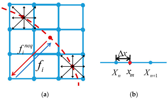
Figure 1.
The proposed non-equilibrium scheme: (a) the interpolation and spread process in two dimensions; (b) the three-point interpolation in one dimension.
- Spread operator and interpolation operator in the non-equilibrium Scheme
According to the Chapman–Enskog expansion analysis [12], expressing as the disturbance expansion, we then obtain
where is the collision scale time. is the equilibrium distribution function, and is the non-equilibrium distribution function.
Note that is the set of Euler coordinate points to be interpolated, and is the set of all Lagrangian marked points.
According to Equations (1) and (2), the discrete interpolation delta function [33] is denoted as
where is the length of the Euler grid, is the spatial dimension, and and are the coordinate in the direction , and Equation (4) can be used for .
Similarly, the discrete spread delta function is denoted as
Interpolation operator from Euler to Lagrange:
For any , through the interpolation function , we assume that the distribution function on the Lagrangian point satisfies
The discrete velocity distribution function should satisfy
where the equilibrium function is constructed with the local velocity , rewriting Equation (10) as
where the density can be calculated via Equation (14).
Then can be obtained from Equations (22)–(24).
We can still use the force model [12] from the Euler point to the Lagrangian point, and, noting in Equation (24) as , we then obtain
where is the equilibrium velocity. [36], [39], and other models can be found in the book [12].
For , we can obtain
Then, we can obtain the expression of the macroscopic force density function from :
The force density function obtained via Equation (27) is much simpler in form than the direct force derived via the stress integration method given by Feng [17], which also means that less calculation noise is generated.
Spread operator from Lagrange to Euler:
For any , through the spread function , the non-equilibrium velocity distribution function of the Euler point can be obtained as
The force density on the Euler point can be obtained from (27). By connecting (10) and (14), the fluid solution process of the IB-LBM can be completed.
The following verifies the order of accuracy in the spread process.
Consider a one-dimensional problem, as shown in Figure 1b, under a three-point interpolation. Then,
Introduce non-equilibrium theory, where is an order of magnitude smaller than [38]:
Hence, we obtain
Therefore, the proposed non-equilibrium scheme has local second-order accuracy during the spread process.
- Optimization of the proposed IB-LBM with approximate force on the IB
Through Equations (20), (21), (23), (26), and (27), an IB-LBM solver in the non-equilibrium distribution function scheme is built.
can be obtained as the force density vector on the Lagrangian point through Equation (27). However, there will be a small amount of the streamline penetration phenomenon, which needs to be corrected via the matrix [19].
Denoting as , and introducing the correction matrix , is then the target matrix:
The correction matrix is given as
where is the spread matrix, is the interpolation matrix, is the Euler step matrix, and is the Lagrangian step matrix, as follows:
It can be seen that the above method needs to invert the matrix, and the actual situation often involves large-scale sparse matrices. Some correction methods have been studied [21,22,28]. This paper proposes an approximate force method to replace the matrix inversion in some IB-LBMs [19].
The approximate force method:
Denoting as , we then obtain
where is the error remainder of .
Using the difference value of before and after transformation to estimate , we then have
where is the error remainder of .
By analogy, we can obtain
Noting , and the induction from (33) and (34), we have
Substituting Equations (37)–(39) into Equation (36), can then be expressed as an infinite series:
If exists and is bounded, then must converge, such that
Usually, taking for (40) to obtain an approximate solution, we then have
- The whole process of the present IB-LBM
Connecting all the equations above, the process of our IB-LBM is shown in Figure 2.
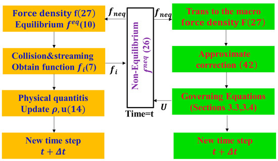
Figure 2.
Flow chart of coupling algorithm via non-equilibrium-IB-LBM.
(1) Starting from time , input into Equation (22) and into the non-equilibrium immersed boundary module (in the middle) and obtain through Equations (23)–(25).
(2) In the fluid module on the left, input to obtain the force density function through Equation (27) and the equilibrium distribution function through Equation (10). In addition, obtain the distribution function via Equation (7) after the collision and stream. At the same time, output the macroscopic physical quantity (14), and update the time step to .
(3) In the solid module on the right, input to obtain the boundary force density via Equation (27), and through the approximate optimization in Equation (42), obtain the immersed boundary velocity from the solid governing equations, such as our Section 4.3 and 4.4, and update the time step to .
4. Results
4.1. Symmetrical Poiseuille Flow with an Immersed Boundary
Poiseuille flow [40] is a common verification test for numerical algorithms as it has an analytical solution. Furthermore, the numerical simulation of Poiseuille flow can also be an engineering reference model. The error analysis and accuracy verification of the present method uses this test.
A computational domain that is different from the conventional Poiseuille flow verification example was designed, as shown in Figure 3, wherein one immersed boundary along the X direction is located in the middle of the flow field. Consider the square area as the fluid domain, where and is the grid length. The four boundaries (the top, the bottom, the left, and the right) are set as periodic boundaries. An immersed boundary is set at the center of the channel. The force density is , and the Reynolds number and the relaxation time remain constant. The initial numbers are in the X direction and in the Y direction. The initial number of Lagrangian grids on the IB is 18 (the grid ratio is approximately 1.11), and the arc lengths between the grids are equal. The grid number of 4 tests (,, , and ) is used. The number of Lagrangian grids per group is also increased by two times.
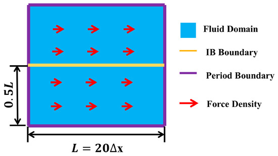
Figure 3.
The computational domain of the symmetrical Poiseuille flow with one IB.
The analytic solution of the plane Poiseuille flow in this paper is expressed as
where is the width of the channel, is the dynamic viscosity, and is the height coordinate in the channel.
The maximum velocity value is located at :
The infinite norm of the error is used in the error analysis and is given as
where is the numerical solution of velocity, and is the analytical solution of velocity in the fluid domain.
The L2 norm of the velocity error is also considered:
The comparison between the analytical solution and the numerical solutions of the four tests is shown in Figure 4. A relatively high fit degree with the analytical solution curve proves the effectiveness of the present algorithm in steady flow. As the LBM uses periodic boundaries, the Y coordinates will be infinitely close to Y = 20 and Y = 0.
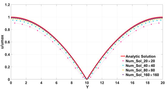
Figure 4.
The comparison of the numerical solutions according to the four grid schemes and the analytic solution.
Table 1 shows the L2 norm and the infinite norm of the error of the four grid schemes. The method proposed in this paper has first-order global accuracy, although we proved the second-order in the spread process. As the many boundary methods of the LBM have only first-order accuracy, considering this IB-LBM, which is 23 times faster than the IBM–Navier–Stokes solver [41], the computational resources in this paper are acceptable.

Table 1.
The L2 norm, infinite norm of the error, and convergence order (rate) values.
A grid independence study was performed to ensure the results were independent of the mesh resolutions, as shown in Table 2. Based on the results in Table 2, we adopted different Lagrangian grids of 10, 20, and 30 with grid ratios of 2, 1, and 0.67 on the immersed boundary, which is sufficient to ensure mesh-independent results (18 was the initial setting).

Table 2.
Grid independence study of Poiseuille flow with four Lagrangian mesh schemes.
4.2. Flow Past a Fixed Circular Cylinder
Flow past a 2D fixed cylinder is a classic test that has experimental results, and many numerical simulation results, and is often taken to validate IB-LBMs [21,22,23,24,25,26]. The accuracy and validity of the present IB-LBM in unsteady flow and the conservative invariance of mass in Equation (42) were to be further verified through this test.
The Reynolds numbers of our test were set as 20, 40, 100, and 200, respectively, and the parameter in (42) is given in this case. The computational domain considers the rectangular domain , where the lattice length . The cylinder diameter , the number of the Lagrangian grids is 72, and the grid ratio is about 1.4. The four boundaries are as follows: the top and bottom boundaries are fixed solid boundaries; the left is the inlet with the velocity , and the right side is the outlet with the velocity gradient being zero. All the boundaries are treated with the non-equilibrium scheme.
The four dimensionless parameters are given as follows: the Reynolds number as ; the Strouhal number ( is the vortex shedding frequency); and the drag coefficient and lift coefficient , which are obtained with
where drag force , lift force , and the subscripts x and y are the x-direction and y-direction in the domain.
Table 3 is a comparison of the results for the three important parameters, the drag coefficient , lift coefficient , and Strouhal number , via the experimental result [42], numerical result [43], and the results of other IB-LBMs [19,23,30]. We see that the parameters of the proposed numerical method are similar to the parameters in other results. The accuracy of the present method is verified in both steady and unsteady flow.

Table 3.
Comparison of the drag coefficient, the lift coefficient, and the Strouhal number when Re = 20, 40, 100, and 200.
Figure 5 shows the curve of the drag coefficient and lift coefficient . The drag coefficient gradually decreases when the Reynolds number increases. When Re = 100 and Re = 200, the data in Table 3 correspond to the curves in Figure 5. When Re = 100 and Re = 200, the lift coefficient curve presents periodic changes, and the period becomes shorter as the Reynolds number increases. The change in the lift coefficient means that the frequency of vortex shedding increases gradually as the Reynolds number increases after the appearance of a Karman vortex street ().
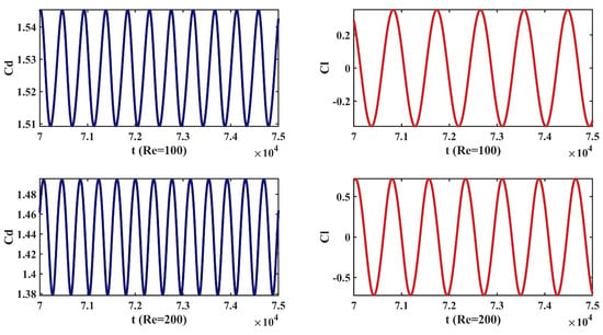
Figure 5.
Drag coefficient curve and lift coefficient curve when Re = 100 and 200.
Figure 6a shows the streamline results of the 4 usual IB-LBMs at Re = 40, which are the penalty method [16], the iterative method [21], the implicit method [19], and the momentum exchange method [18]. Comparing our streamline results when Re = 40 in Figure 6b, our proposed method has almost no streamline penetration phenomenon. Such results can prove that the present method can ensure local mass conservation at the interface under unsteady flow; the no-slip boundary condition can be effectively guaranteed; and the parameter setting in Equation (42) is effective.
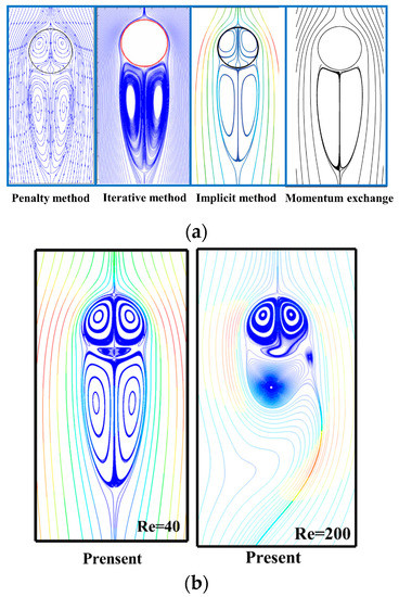
Figure 6.
Streamline diagrams: (a) four popular method results when Re = 40; (b) result of present method when Re = 40 and 200.
4.3. Sedimentation and Collision of Moving Particles
Particle–fluid interaction problems have been widely encountered in nature and engineering, such as sediment suspension in rivers and cell transport in biology. There are a large number of numerical simulation cases for particle–fluid motion [32], and we used the numerical solution of double-particle sedimentation to verify our method [16,18,20].
For particles in the fluid domain, they can be regarded as a moving rigid body and satisfy the synthetic motion equation:
where and are the total force and torque on the particle, and the total force includes the gravity/buoyancy force, and the hydrodynamic and particle collision force . is the center of mass of the particle , and is the radius of particle . is the moment inertia, is the mass of the particle, and is the density of the particle. Moreover, denotes the collision forces of particle–particle and particle–wall collisions, respectively. , are constant by the setting (see [16]), and is the threshold.
The channel of the computational domain is , which means the width is 2 cm (x-direction), and the height is 8 cm (y-direction). The particle density is , and the radii of the particles are 0.1 cm. Initially, particle 2 is set at the point (0 cm, 7.2 cm), and then particle 2 is set at the point (0 cm, 6.8 cm). The relaxation time is 0.65, and more related parameters can be seen in [16,18,20].
Figure 7 is a comparison of the motion trajectory results between this case and other cases [16]. It can be seen that the results of this case are basically consistent with other cases. Figure 7a shows the time of the separation of the two particles is 1.5 s, and this is because particle 2 is located in the wake of particle 1. As the two particles approach and collide, particle 1 has a larger movement range on the X-axis than particle 2, as shown in Figure 7b, because the component of the collision force of particle 2 on the Y-axis is positive, and particle 2 has a bounce-back process, as shown in Figure 7a.
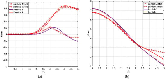
Figure 7.
The motion trajectory compared with paper [16]: (a) motion trajectory on X-axis with time t (s); (b) motion trajectory on Y-axis with time t (s).
Figure 8 is the overall trajectory of the particles accompanied by the change in vorticity. The particle displays a motion that is the specific trajectory on the 2D plane corresponding to Figure 7a,b. We achieve an acceptable degree of fit with [16] in Figure 7a,b, which also means that we achieve similar motion trajectories on the 2D plane to the results by Feng [16] (more similar results can be seen in [18,19]). In the middle and early part of the time, particle 1 chases particle 2, and it can be seen that the vorticity changes with time increases. The overall motion lasts for 5 s. The collision process occurs when t = 1.5 s, and the separation process occurs when t is greater than 2 s. The result of this case shows the applicability and accuracy of this method in simulating movable rigid bodies.
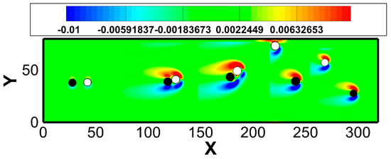
Figure 8.
The overall trajectory of the particles with time change accompanied by the vorticity.
4.4. A Flexible Filament Fixed at One End
Flexible bodies interacting with surrounding fluid flow are commonplace; the motion of flexible filaments in a flow is an abstract model of these phenomena. Over the years, many simulations of flexible filaments have been studied [44,45,46].
Considering an inextensible flexible filament of length , its deformation equations can be written as
where is the linear density of the filament, is the bending coefficient, and is the tension force along the filament, which is determined by the constraint of the inextensibility condition. The boundary conditions at the fixed end and free end closed the equations. Additionally, the finite difference method is applied to solve the equations.
We used the computational domain , and the boundary conditions were set in the same scheme as in case 4.2, but with . A fixed end of a flexible filament is located at , setting the length along the X direction. When the Reynolds number is determined, the parameters of and are adjusted to obtain the test results.
Figure 9 is a comparison diagram of the trajectory of the flexible filaments. The parameters in this article are set to . According to the parameter strategy in this paper, the tail trajectory, which is very similar to that in the other literature, can be obtained. The trajectory is symmetrical, like the writing of the Arabic number 8. This proves the accuracy and applicability of this paper in simulating flexible bodies.
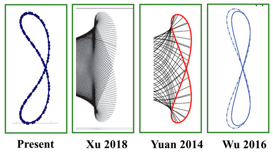
Figure 9.
Comparison diagram of the tail movement trajectory of the flexible filament with three cases: Xu [46], Yuan [24] and Wu [20].
Figure 10a,b shows the filament motion trajectory diagrams. The initial setting filament length , the other parameters , and 2 sets of parameter comparisons are given as (a) and (b). From the comparison of (a) and (b), it can be seen that the overall motion shape of the flexible filament changes greatly with small changes in the parameters, which is why the results of the papers on the flexible filament model are different in terms of the overall motion shape [44,45,46]. When increases, the overall movement amplitude decreases approximately from the (65–105) of (a) to the (60–100) of (b) in the Y direction. Determined by Equation (49), the amplitude of the filament movement at the tail is greater than that at the middle. According to our results, when the parameter is less than 0.05, the overall program breaks due to excessive motion amplitude. Moreover, when the parameter is greater than 0.13, the overall motion amplitude decreases to a quasi-static state.
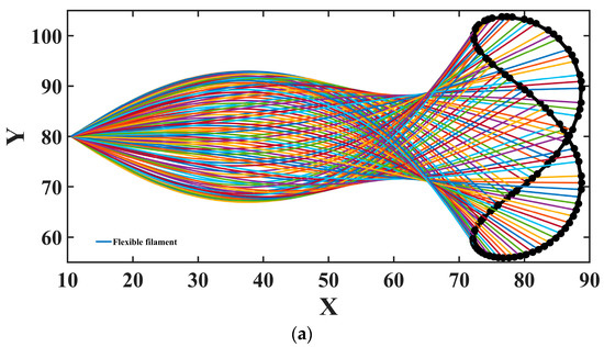
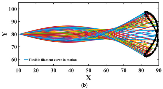
Figure 10.
The filament motion trajectory diagrams: (a) ; (b) .
Figure 11 is the wake vorticity diagram of the flexible filament at different Reynolds numbers. When the Reynolds number is 150 with 0.2 T and 0.5 T (where T is the motion period of the filament), the Karman vortex street is regular. When the Reynolds number is 600 with 0.1 T and 0.5 T (b), the vortex separation frequency presents an unstable situation. Moreover, the successful simulation of the large deformation of the flexible body denotes a certain stability of our method.
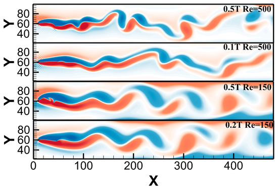
Figure 11.
Comparison of vortex contours of flexible filaments under four schemes.
5. Conclusions
The final conclusions are as follows:
(1) This paper proposed a non-equilibrium scheme for the IB-LBM, which is an extension of the non-equilibrium theory of the LBM in Equations (22)–(24) and (28). In the IB-LBM interpolation process, the explicit force of the immersed boundary under mesoscopic conditions with the non-equilibrium scheme and the force model from the LBM is realized in Equation (27). The explicit scheme can be a simple form compared with the implicit scheme in [19] and the explicit direct force in Equation (16). The application of our proposed non-equilibrium scheme (that is subsequently optimized via an approximate force) to numerical simulations is effective, which demonstrates the feasibility of the proposed scheme modeled using non-equilibrium theory.
(2) For the IBM or IB-LBM, the coupling process consists of the spread process and the interpolation process, so the numerical results must include the two processes together. We give a theoretical proof to the non-equilibrium scheme that has local second-order accuracy in the spread process in Equation (31). However, it only has first-order global accuracy in Table 1, which is because there is only local first-order accuracy in the interpolation process in Equation (22). The reason is that the delta function in Equations (1) and (2) is difficult to replace, which leads to first-order accuracy for IBMs or IB-LBMs. Therefore, this is one of the reasons why the IB-LBM or IBM has become a current research hotspot [7]. The proof of local second-order accuracy in the spread process will simplify the issue of global second-order accuracy, that is, researchers who are interested in the IB-LBM only need to conduct modeling research on the interpolation process.
(3) A non-iterative approximation method in Equation (42) is used to correct the explicit force via the non-equilibrium scheme in Equation (27) on the interface, and a better streamline diagram is obtained in Figure 6a,b (with the disappearance of streamline penetration), which almost strictly satisfies the no-slip boundary condition. The advantage of this explicit force optimized using the non-iterative approximation method is that there is no need for matrix inversion [19] or iterative solution [21], but it can obtain the same results in Figure 6a,b. Furthermore, Equation (42) is also an explicit scheme.
Author Contributions
Conceptualization, W.S. and B.L.; methodology, B.L.; software, B.L.; validation, B.L. and W.S.; formal analysis, W.S.; investigation, B.L.; resources, B.L.; data curation, B.L and W.S.; writing—original draft preparation, B.L.; writing—review and editing, B.L.; visualization, B.L.; supervision, W.S; project administration, W.S; funding acquisition, W.S. All authors have read and agreed to the published version of the manuscript.
Funding
This work was supported by the National Key Research and Development Program of China (grant no. 2018YFA0703300) and the Natural Science Foundation of Jilin Province, China (grant no. 20200201278JC).
Institutional Review Board Statement
Not applicable.
Informed Consent Statement
Not applicable.
Data Availability Statement
Not applicable.
Acknowledgments
The authors are grateful to Chengchun Zhang for his guidance, management work and financial support for this project. We have added his work to the work content list.
Conflicts of Interest
The authors declare no conflict of interest.
References
- Hou, G.; Wang, J.; Layton, A. Numerical methods for fluid-structure interaction—A review. Commun. Comput. Phys. 2012, 12, 337–377. [Google Scholar] [CrossRef]
- Anderson, R.W.; Elliott, N.S.; Pember, R.B. An arbitrary Lagrangian–Eulerian method with adaptive mesh refinement for the solution of the Euler equations. J. Comput. Phys. 2004, 199, 598–617. [Google Scholar] [CrossRef]
- Longatte, E.; Bendjeddou, Z.; Souli, M. Application of arbitrary Lagrange Euler equationtions to flow-induced vibration problems. J. Pressure Vessel Technol. 2003, 125, 411–417. [Google Scholar] [CrossRef]
- Liu, M.B.; Liu, G. Smoothed particle hydrodynamics (SPH): An overview and recent developments. Arch. Comput. Methods Eng. 2010, 17, 25–76. [Google Scholar] [CrossRef]
- Antoci, C.; Gallati, M.; Sibilla, S. Numerical simulation of fluid interaction by SPH. Comput. Struct. 2007, 85, 879–890. [Google Scholar] [CrossRef]
- Peskin, C.S. Flow patterns around heart valves: A numerical method. J. Comput. Phys. 1972, 10, 252–271. [Google Scholar] [CrossRef]
- Griffith, B.E.; Patankar, N.A. Immersed methods for fluid–structure interaction. Annu. Rev. Fluid Mech. 2020, 52, 421–448. [Google Scholar] [CrossRef]
- Ou, Z.; Chi, C.; Guo, L.; Thévenin, D. A directional ghost-cell immersed boundary method for low Mach number reacting flows with interphase heat and mass transfer. J. Comput. Phys. 2022, 468, 111447. [Google Scholar] [CrossRef]
- Yousefzadeh, M.; Battiato, I. High order ghost-cell immersed boundary method for generalized boundary conditions. Int. J. Heat Mass Transf. 2019, 137, 585–598. [Google Scholar] [CrossRef]
- McNamara, G.R.; Zanetti, G. Use of the Boltzmann equation to simulate lattice-gas automata. Phys. Rev. Lett. 1988, 61, 2332. [Google Scholar] [CrossRef]
- Duda, B.; Fares, E. Application of a Lattice-Boltzmann method to the separated flow over the NASA hump. In Proceedings of the 54th AIAA Aerospace Sciences Meeting, San Diego, CA, USA, 4–8 January 2016; p. 1836. [Google Scholar]
- Krüger, T.; Kusumaatmaja, H.; Kuzmin, A.; Shardt, O. The Lattice Boltzmann Method: Principles and Practice, 1st ed.; Springer International Publishing: Cham, Switzerland, 2017; pp. 22–670. ISBN 978-3-319-44649-3. [Google Scholar]
- Gallivan, M.A.; Noble, D.R.; Georgiadis, J.G.; Buckius, R.O. An evaluation of the bounce-back boundary condition for lattice Boltzmann simulations. Int. J. Numer. Methods Fluids 1997, 25, 249–263. [Google Scholar] [CrossRef]
- Yin, X.; Zhang, J. An improved bounce-back scheme for complex boundary conditions in lattice Boltzmann method. J. Comput. Phys. 2012, 231, 4295–4303. [Google Scholar] [CrossRef]
- Saurabh, K.; Solovchuk, M.; Sheu, T.W.H. Investigating ion transport inside the pentameric ion channel encoded in COVID-19 E protein. Phys. Rev. E 2020, 102, 052408. [Google Scholar] [CrossRef] [PubMed]
- Feng, Z.G.; Michaelides, E.E. The immersed boundary-lattice Boltzmann method for solving fluid–particles interaction problems. J. Comput. Phys. 2004, 195, 602–628. [Google Scholar] [CrossRef]
- Feng, Z.G.; Michaelides, E.E. Proteus: A direct forcing method in the simulations of particulate flows. J. Comput. Phys. 2005, 202, 20–51. [Google Scholar] [CrossRef]
- Niu, X.D.; Shu, C.; Chew, Y.T. A momentum exchange-based immersed boundary-lattice Boltzmann method for simulating incompressible viscous flows. Phys. Lett. A 2006, 354, 173–182. [Google Scholar] [CrossRef]
- Wu, J.; Shu, C. Implicit velocity correction-based immersed boundary-lattice Boltzmann method and its applications. J. Comput. Phys. 2009, 228, 1963–1979. [Google Scholar] [CrossRef]
- Wu, J.; Zhan, J.; Zhao, N.; Wang, T. A robust immersed boundary-lattice Boltzmann method for simulation of fluid-structure interaction problems. Commun. Comput. Phys. 2016, 20, 156–178. [Google Scholar] [CrossRef]
- Kang, S.K.; Hassan, Y.A. A comparative study of direct-forcing immersed boundary-lattice Boltzmann methods for stationary complex boundaries. Int. J. Numer. Methods Fluids 2011, 66, 1132–1158. [Google Scholar] [CrossRef]
- Seta, T.; Rojas, R.; Hayashi, K.; Tomiyama, A. Implicit-correction-based immersed boundary–lattice Boltzmann method with two relaxation times. Phys. Rev. E 2014, 89, 023307. [Google Scholar] [CrossRef]
- Hu, Y.; Yuan, H.; Shu, S.; Niu, X.; Li, M. An improved momentum exchanged-based immersed boundary–lattice Boltzmann method by using an iterative technique. Comput. Math. Appl. 2014, 68, 140–155. [Google Scholar] [CrossRef]
- Yuan, H.Z.; Niu, X.D.; Shu, S.; Li, M.; Yamaguchi, H. A momentum exchange-based immersed boundary-lattice Boltzmann method for simulating a flexible filament in an incompressible flow. Comput. Math. Appl. 2014, 67, 1039–1056. [Google Scholar] [CrossRef]
- Zhou, Q.; Fan, L.S. A second-order accurate immersed boundary-lattice Boltzmann method for particle-laden flows. J. Comput. Phys. 2012, 268, 269–301. [Google Scholar] [CrossRef]
- Wang, W.Q.; Yan, Y.; Liu, G.R. An IB-LBM implementation for fluid-solid interactions with an MLS approximation for implicit coupling. Appl. Math. Model. 2018, 62, 638–653. [Google Scholar] [CrossRef]
- Afra, B.; Nazari, M.; Kayhani, M.H.; Delouei, A.A.; Ahmadi, G. An immersed boundary-lattice Boltzmann method combined with a robust lattice spring model for solving flow–structure interaction problems. Appl. Math. Model. 2018, 55, 502–521. [Google Scholar] [CrossRef]
- Tao, S.; He, Q.; Chen, J.; Chen, B.; Yang, G.; Wu, Z. A non-iterative immersed boundary-lattice Boltzmann method with boundary condition enforced for fluid–solid flows. Appl. Math. Model. 2019, 76, 362–379. [Google Scholar] [CrossRef]
- Wang, Z.; Wei, Y.; Qian, Y. A bounce back-immersed boundary-lattice Boltzmann model for curved boundary. Appl. Math. Model. 2020, 81, 428–440. [Google Scholar] [CrossRef]
- Qin, J.; Kolahdouz, E.M.; Griffith, B.E. An immersed interface-lattice Boltzmann method for fluid-structure interaction. J. Comput. Phys. 2012, 428, 109807. [Google Scholar] [CrossRef]
- Yang, F.; Gu, X.; Xia, X.; Zhang, Q. A peridynamics-immersed boundary-lattice Boltzmann method for fluid-structure interaction analysis. Ocean Eng. 2012, 264, 112528. [Google Scholar] [CrossRef]
- Qin, S.; Jiang, M.; Ma, K.; Su, J.; Liu, Z. Fully resolved simulations of viscoelastic suspensions by an efficient immersed boundary-lattice Boltzmann method. Particuology 2023, 75, 26–49. [Google Scholar] [CrossRef]
- Peskin, C.S. The immersed boundary method. Acta Numer. 2002, 11, 479–517. [Google Scholar] [CrossRef]
- Bhatnagar, P.L.; Gross, E.P.; Krook, M. Title of the article. A model for collision processes in gases. I. Small amplitude processes in charged and neutral one-component systems. Phys. Rev. 1954, 94, 511. [Google Scholar] [CrossRef]
- He, X.; Luo, L.S. Theory of the lattice Boltzmann method: From the Boltzmann equation to the lattice Boltzmann equation. Phys. Rev. E 1997, 56, 6811. [Google Scholar] [CrossRef]
- Guo, Z.; Zheng, C. Discrete lattice effects on the forcing term in the lattice Boltzmann method. Phys. Rev. E 2002, 65, 046308. [Google Scholar] [CrossRef] [PubMed]
- Qian, Y.H.; d’Humières, D.; Lallemand, P. Lattice BGK models for Navier-Stokes equation. Europhys. Lett. 1992, 17, 479. [Google Scholar] [CrossRef]
- Zhao-Li, G.; Chu-Guang, Z.; Bao-Chang, S. Non-equilibrium extrapolation method for velocity and pressure boundary conditions in the lattice Boltzmann method. Chin. Phys. 2002, 11, 366. [Google Scholar] [CrossRef]
- Shan, X.; Chen, H. Lattice Boltzmann model for simulating flows with multiple phases and components. Phys. Rev. E 1993, 47, 1815. [Google Scholar] [CrossRef]
- Carlson, D.R.; Widnall, S.E.; Peeters, M.F. A flow-visualization study of transition in plane Poiseuille flow. J. Fluid Mech. 1982, 121, 487–505. [Google Scholar] [CrossRef]
- Su, S.W.; Lai, M.C.; Lin, C.A. An immersed boundary technique for simulating complex flows with rigid boundary. Comput. Fluids 2007, 36, 313–324. [Google Scholar] [CrossRef]
- Tritton, D.J. Experiments on the flow past a circular cylinder at low Reynolds numbers. J. Fluid Mech. 1959, 9, 547–567. [Google Scholar] [CrossRef]
- Calhoun, D. A Cartesian grid method for solving the two-dimensional stream function-vorticity equations in irregular regions. J. Comput. Phys. 2002, 176, 231–275. [Google Scholar] [CrossRef]
- Zhu, L.; Peskin, C.S. Simulation of a flapping flexible filament in a flowing soap film by the immersed boundary method. J. Comput. Phys. 2002, 179, 452–468. [Google Scholar] [CrossRef]
- Huang, W.X.; Shin, S.J.; Sung, H.J. Simulation of flexible filaments in a uniform flow by the immersed boundary method. J. Comput. Phys. 2007, 226, 2206–2383. [Google Scholar] [CrossRef]
- Xu, Y.Q.; Wang, M.Y.; Liu, Q.Y.; Tang, X.Y.; Tian, F.B. External force-induced focus pattern of a flexible filament in a viscous fluid. Appl. Math. Model. 2018, 53, 369–383. [Google Scholar] [CrossRef]
Disclaimer/Publisher’s Note: The statements, opinions and data contained in all publications are solely those of the individual author(s) and contributor(s) and not of MDPI and/or the editor(s). MDPI and/or the editor(s) disclaim responsibility for any injury to people or property resulting from any ideas, methods, instructions or products referred to in the content. |
© 2023 by the authors. Licensee MDPI, Basel, Switzerland. This article is an open access article distributed under the terms and conditions of the Creative Commons Attribution (CC BY) license (https://creativecommons.org/licenses/by/4.0/).