1. Introduction
Human life is precious, and the loss of life can be reduced considerably by using robots in the armed forces. Nowadays, all military organizations use such robots to perform perilous tasks in chancy environments [
1]. In the war field, we control our military tanks by personal computer wirelessly using Wi-Fi or RF (radio frequency) communication systems with live video transmission and image processing techniques that will target the felon automatically or manually using the laser gun. These kinds of robots are very helpful in conducting various remote combat missions and in identifying as well as eliminating different terrorist activities within the border, and across the border. In addition, night vision cameras can also be used on the robot to conduct surveillance even in the darkness of night [
2,
3].
Conventionally, military robots were not capable of live video transmission; they only captured video and stored it in their storage device, but now with live video transmission, the military can react in more detail presently. Getting information through live video transmission is also helping them to be prepared for the situation ahead. Furthermore, this live video transmission can be used for different computations, as used in this project for facial recognition [
4]. In addition, with the surveillance feature, this robot can also be used as a spy robot. Spy robots were first introduced in the early 1940s in World War II. The purpose of these robots was to reduce the number of victims of war, as the entrance of a person into the enemy territory was very difficult, and accessing sensitive information for secret operations was nearly impossible; hence these robots were introduced. However, the major flaw was that these robots were not wireless. Another flaw was the storage of video streaming which requires a large amount of disk storage [
4].
Unmanned ground vehicles (UGV) were introduced in the early 1970s, a great revolution in the history of robotics. But there were also many flaws in these UGVs as they were wirelessly controllable over only a very small range like 50–100 m. The only advancement in these spy robots was that they were wireless, but the flaw in their video transmission was the same. This flaw has also been covered in this project; it can be controlled wirelessly over a range of approximately 1.2 km with a clear line of sight. However, if the line of sight is unclear, it might reduce the effective range of the wireless control system [
5].
Then, in the early 2000s, modern UGVs were invented. They were controllable over a long range of hundreds of meters and capable of live video transmission. Still, they were controlled manually using joysticks and targeting the felon manually by viewing the target on the screen. To improve this flaw, automatic laser targeting has been introduced in our project. Automated laser targeting can also help eliminate ground-to-air targets manually and eliminate ground-ground human targets automatically and manually [
4].
Along with the advancement of the control features of robots from wire transmission to RF and then with long-range RF communications, Wi-Fi-based control features have also been in use for a few years, in which mobile robots are controlled using graphical user interfaces based on different programming languages like Java, JavaScript, node, C
++ and most famous Python. These GUIs are built on personal computers or laptops, and robots can be controlled by different commands from GUI [
6].
A few years earlier, we saw some spy and normal robots, controllable by smartphones. The smartphone has been a great invention in human history. Modern smartphones have been equipped with GPS, compass, and some other great features which are very useful, and the use of the mobile phone in such projects makes it compact and makes the man–machine interface more attractive [
7].
Advancement in live video transmission and computation of that video has increased daily because of continuous research in artificial intelligence, machine learning, computer vision, and robotics. This research urges researchers and developers to make robots controllable over a wide range of applications equipped with live video transmission, which can be used for various operations for the benefit of mankind. For example, monitoring flooded areas and estimating damages due to floods [
8]. Another example of advancement in image processing leads to farming facilities in which avoiding diseases and checking pests and other harmful agents seems impossible without sensors. However, installing sensors on wide land is not cost-effective. Hence, image processing techniques have been used to identify the harmful agents by capturing pictures of leaves and sending a notification to farmers through IoT and other means to control actions [
9].
The advancement in the field of image processing is not confined to the above applications but has been extended to military applications. For example, spy robots have been seen equipped with a color sensor, which helps them to camouflage based on the environment. Advanced robots now use image processing techniques to camouflage rather than using color sensors [
5]. Another application in military robots has been seen in recent years: motion tracking. Based on motion tracking, several operations can now be done, for example, triggering a security alarm or remote elimination using a controllable weapon [
10].
In recent years spy robots with live video transmission have been used to conduct highly dangerous remote operations, for example, surveillance in terrorist areas in which mines have been planted. In the early stages, these robots were used to defuse the mines using remote operations. However, with the advancement of technology, they can also be used to conduct search operations on enemy ground to detect and defuse mines. Furthermore, mine detection and motion tracking were initially based on the image subtraction algorithm, also known as SAD [
11].
Moreover, in armies of under-developed countries, no such projects have yet to detect targets automatically with the database feed. In our project, unlike a traditional gun, the robot uses a laser gun to detect the target using image processing automatically; then, it will shoot it with a laser gun. The laser gun is used in advanced military projects nowadays; high-power laser guns have a variety of applications [
12]. For example, it has been used for the elimination of water-to-air targets. Similarly, advanced militaries are using laser guns to shoot down ground-to-air targets, i.e., enemy drones, etc. [
13,
14].
Moreover, in our project, the turret, equipped with a laser gun, can also be controlled manually in case the facial features are unclear or we find a potential risk in the live transmission that is not in our database.
As this robot is wireless and equipped with the advantage of live video transmission, there is no need to install expensive hard drives to store the data on the robot. It will also help reduce weight significantly. On the contrary, this video streaming can be used in real-time to act. We can also store the video on any PC in headquarters, not on the robot.
To improve the processing speed of images taken from the live video transmission and to implement more accurate and real-time facial recognition, an advanced algorithm has been used in this project which processes the images in a matter of seconds and not only detects the specified target but also processes real-time localization of the target within the frame of reference. This real-time localization helps calculate the exact position of the target in the structure of reference using the LBPH algorithm [
15]. Some existing works also used the LBPH algorithm, where authors [
16] used this algorithm in drone technology; the system provides 89.1% efficiency. In another research study [
16], the LBPH algorithm is built into drone technology that exhibits 98% efficiency. In the proposed research, an intelligent LBPH algorithm is developed in radio-controlled UGV. The difference between the works [
16,
17] and ours is that although we employ many samples—roughly 50 for each object—and the number can be expanded to an endless number, the recognition accuracy improves as the number of samples increases. Therefore, a 99.8% precision factor is something we are capable of. Furthermore, since we have improved the database with many samples, we can identify numerous people simultaneously. In addition, we used a single high-definition camera on the robot because the mobile robot’s visual control interface, just one camera, can make it simple to operate [
18].
After exact coordinates are found, it draws a rectangle around the face of the target, and the coordinates of this rectangle are sent to the robot wirelessly over Wi-Fi. As the person moves in the graphical video frame of reference, an image processing technique named object localization is used to track the movement of the face in real-time [
19,
20,
21].
Then, with basic mathematics, conversion is performed using the coordinates, and the aim of the turret is controlled. As mentioned earlier, this spy robot is controllable over a wide range of km over an RF line. Previously these kinds of spy robots could not communicate on secure RF lines, and this communication could be tempered at any time. Still, in this project, RF communication is performed over secure lines. As mentioned earlier, this robot can be controlled manually and has two modes. The first is a radio controller, and the other is a Python-based GUI. The radio controller comprises four analog channels and three digital channels. Two analog channels are used to control the movement of the robot, two for the movement of the turret, and digital channels are used for laser targeting, etc.
2. Methodology and Hardware
HMI for this robot is a Python-based GUI application and a radio controller used to control the robot’s movement. This spy robot operates in 2 modes which are as follows:
Manual mode
Semi-Automatic mode.
In “manual mode”, the position of the turret, the laser targeting, and the robot’s movement are controlled manually using the GUI application or the radio controller. The radio controller comprises a joystick to control the movement of the robot and another joystick for the movement of the turret in 2 directions. However, in Semi-Automatic mode, the turret’s position depends upon the face’s position in the video frame, and the shooting down of the target whose ID is already in the “Database” is done automatically by the facial recognition algorithm using the laser weapon. The general working of our intelligent robot can be understood by the flowchart shown in
Figure 1.
The facial recognition algorithm is also based on Python; for compiling the algorithm, PyCharm was used. Haar-Cascade classifiers and the linear binary pattern histogram (LBPH) algorithm are used to recognize the face of the person in the image taken from the video. This whole procedure is divided into basically 3 sections:
In the 1st section of ‘Dataset’, the algorithm is provided with the sample images of the target. It assigns the target a unique ID and saves it in the database. Datasets can also be made in 2 different ways. The first method is that we have one picture to train our algorithm, but this method is less accurate. The second method is to capture several sample images of a single target and create a mini dataset of each target, saving samples with a unique ID. Currently, the algorithm in this project has been trained to capture and save up to 50 samples of each target in the directory, as shown in
Figure 2.
The picture is cropped to the boundary area of the face and is conducted using face detection based on the Haar-cascade algorithm; sample pictures do not include any background. As Haar-cascade is based on a linear binary pattern histogram, colored image samples are converted into grayscale images for quick processing compatible with LBPH [
15].
In the 2nd section, ‘Trainer’, the algorithm is trained for the sample images stored in the database. The first step moves to the dataset’s directory, where sample images are stored. Then, it imports all the images stored in the directory, applies the LBPH recognizer to identify the faces, and applies the Haar-cascade classifier. After that, it stores the training file “yml” extension, which is further used by the recognizer.
In the final section, ‘Recognizer,’ the algorithm displays the live video streaming on the PC screen. If a person comes in front of the camera, the algorithm takes a picture of the person. Then, it starts matching that picture with the sample images of the unique ID stored in the dataset trainer file created in the previous section. The same method will be implemented as in the dataset in which it converts the images into grayscale and then implements the detector, which determines the features of the face and changes the area of focus to the face region, then it matches with the dataset. If the captured image matches the one stored in the dataset with the unique ID, then the name of the target is displayed on the screen.
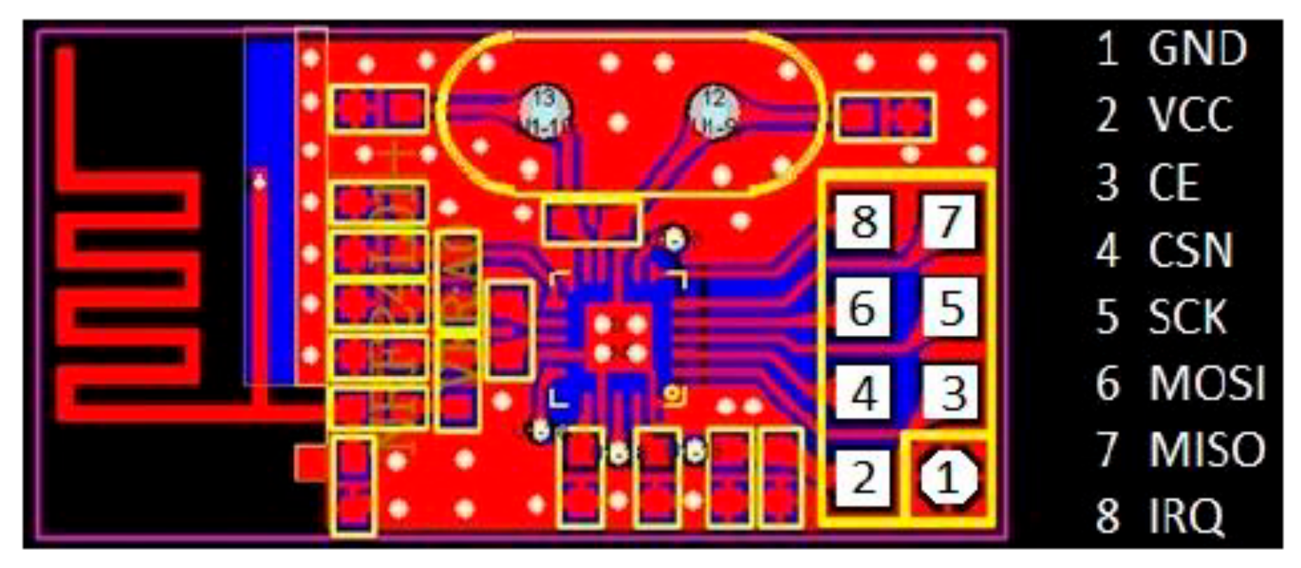
When the facial recognition is done, the algorithm of ‘Recognizer’ performs another task of ‘tracking.’ The ‘Recognizer’ algorithm determines the coordinates of the face of the target on the screen and then sends those coordinates to the microcontroller by serial communication. These coordinates are then transmitted to the other microcontroller, which is the CPU of the robot, wirelessly, using RF-based secure lines over 2.4 GHz. To transmit these tracking coordinates or the other commands to control the robot movement, NRF modules are used. The PCB layout of the transmitting NRF module is shown below in
Figure 3.
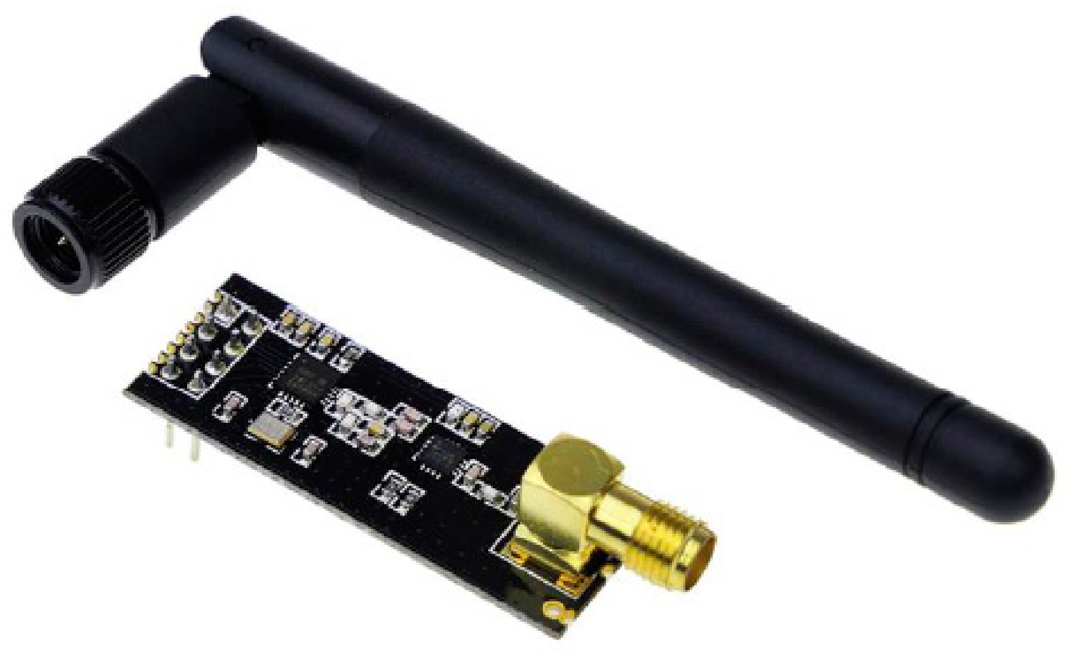
NRF modules operate on 2.4 GHz and have a wide range of up to several km. The range of NRF modules can be increased using an antenna, as shown below in
Figure 4.
These NRF modules operate over SPI (Serial Peripheral Interface) protocol. This protocol enables a server where several ‘slave’ devices can be controlled using a single ‘Master’ device. Specific pins of the microcontroller are used in this protocol; one of those pins is ‘CE’, which enables the ‘Clock’ pin for the specific ‘slave’ device. Another feature of the NRF modules is their ‘bidirectional communication.’ There is a wide range of air data rates supported by NRF modules, i.e., 250 Kb/s–2 Mb/s. Furthermore, the no. of channels of the NRF module is ‘32’, meaning 32 devices can be controlled simultaneously.
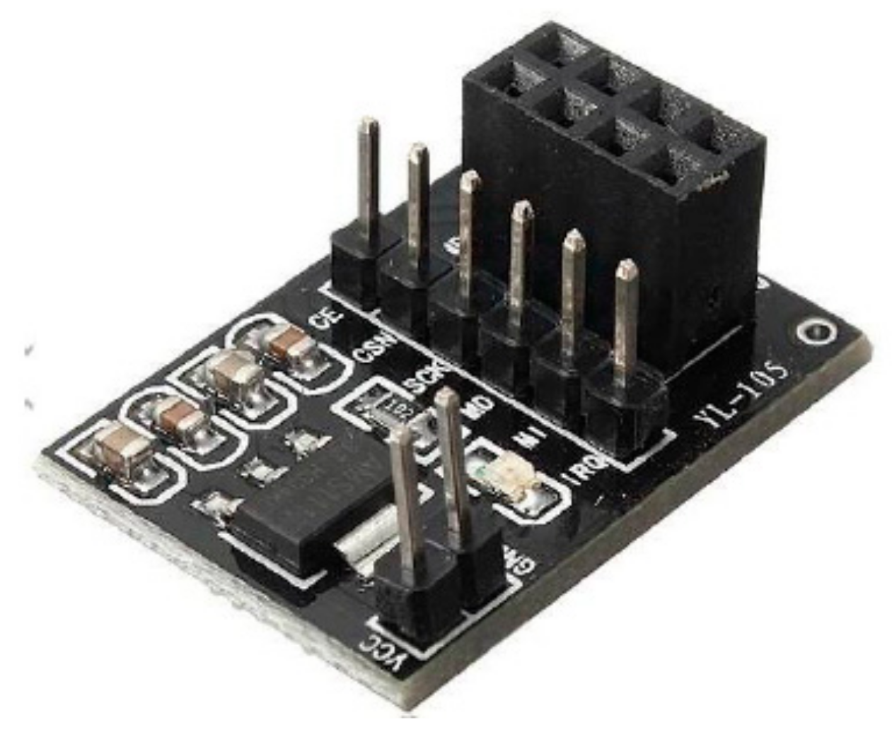
Along with the NRF modules, NRF adapters are also used to regulate the supply voltage and to keep the data packets intact in case of any loss. These adapters are useful for microcontrollers like Arduino, ESP, and Atmel Cortex M3. Because these microcontrollers work on 5 V digital or analog Input/Output, but the NRF module operates on 1.9–3.6 V to regulate the supply voltage, adapters have been used. It also consists of bypass capacitors, increasing the module’s communication reliability. The physical assembly of the NRF adapter module is shown below in
Figure 5.
It also contains a 4*2 female connector for easy plug-in of NRF modules, one 6*1 male connector for ease of SPI communication with the microcontroller, and a 2*1 male connector for supply voltage. In addition, there is an LED, which also ensures the working of the NRF adapter. The overall specification of the NRF adapter module is given below in
Table 1.
2.1. Hardware Design
2.1.1. Mechanical Design
The mechanical model of the spy robot is a tank-type robot consisting of a rack and pinion as driving mechanisms. This driving mechanism has been used keeping in mind the application of the robot. Because this robot has applications in military operations and remote areas, which are mostly rough in surface, this rack and pinion driving mechanism will lead to more efficient movement on different surfaces [
22,
23,
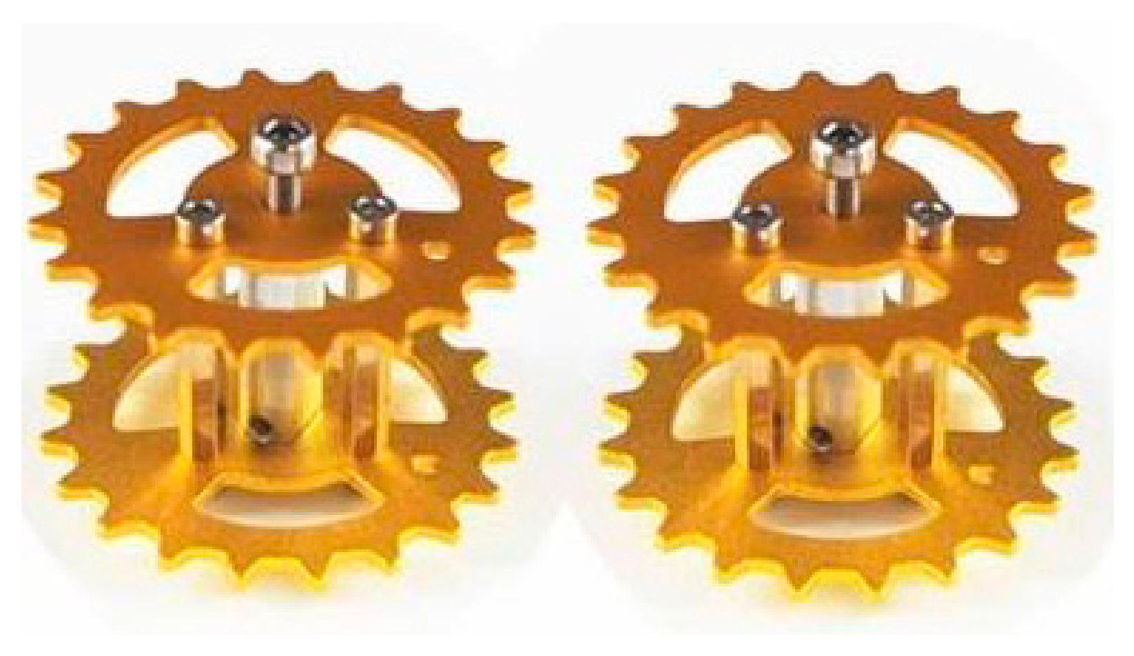
24]. Basically, 2 encoded DC gear motors have been installed in this project diagonally to control the robot’s movement. Specifications of gears are given below in
Table 2, and hardware assembly is in
Figure 6.
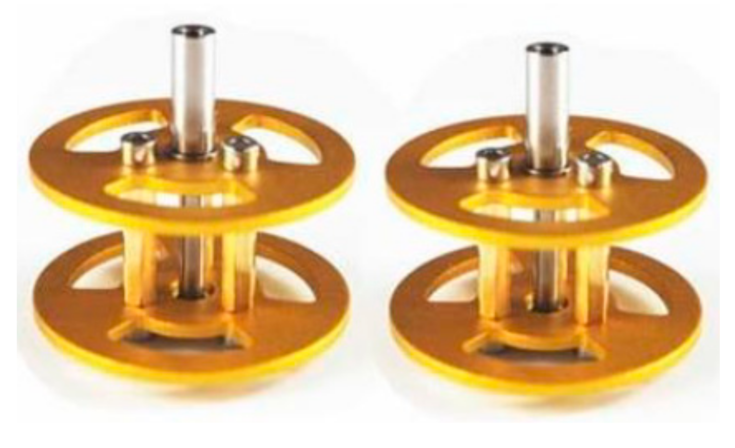
There are also some bearing wheels to assist the driving mechanism of the caterpillar belt to work smoothly. This also helps them travel over rough surfaces. The bearing wheels of this robot can be visualized below in
Figure 7.
Specifications of the bearings are given in
Table 3.
A 2-DOF “tilt-pan” mechanism is installed on the robot based on the metallic gear servo motors to control the turret’s position. This involves 2 brackets in which servo motors can be assembled, as given below in
Figure 8.
A plastic-based caterpillar belt has been used in this project to keep the weight of the robot within the limit. Specifications of the caterpillar belt are as follows in
Table 4:
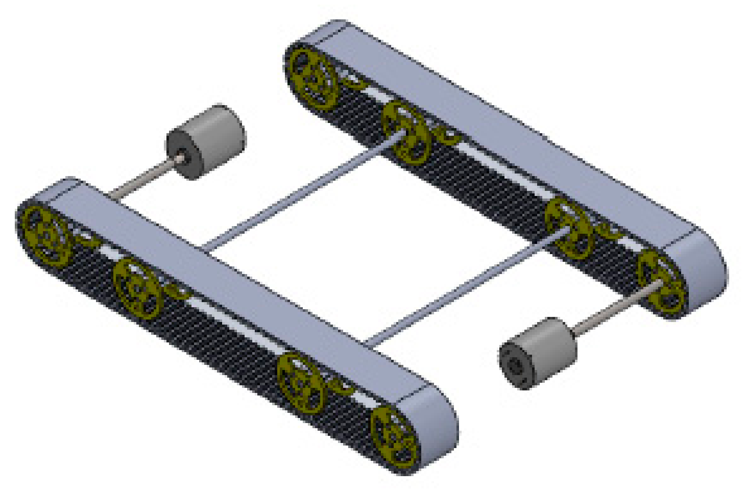
Overall, the CAD model of the mechanical assembly of the robot base is given below in
Figure 9.
2.1.2. Electronic Design
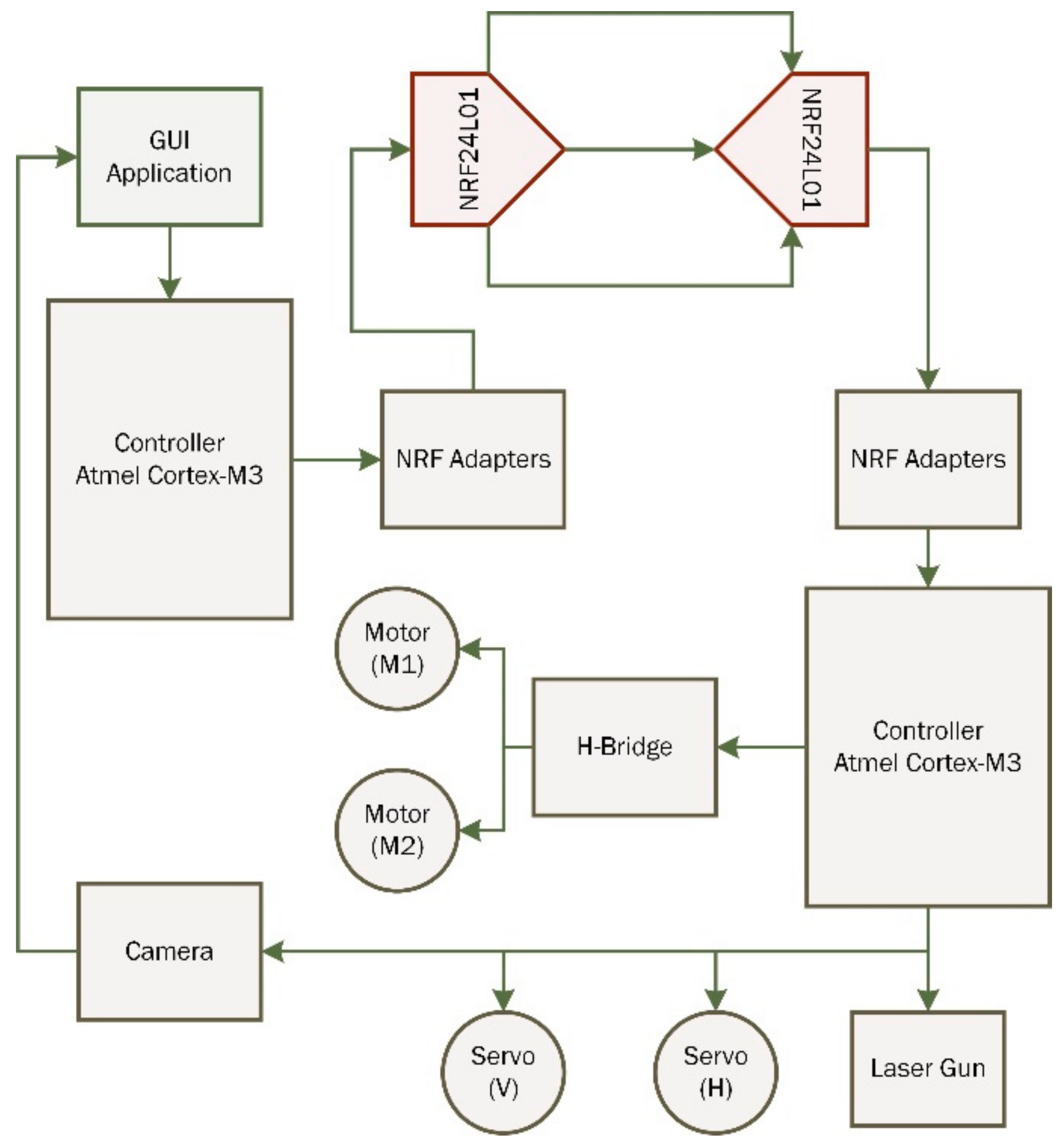
The major electronic part of this robot is NRF24L01 modules which transmit and receive the signals to perform required tasks. NRF adapter bases regulate the power supply to the NRF modules and smooth the data packets’ transmission. The general working of the electronic system of our intelligent robot can be understood from the block diagram shown in
Figure 10.
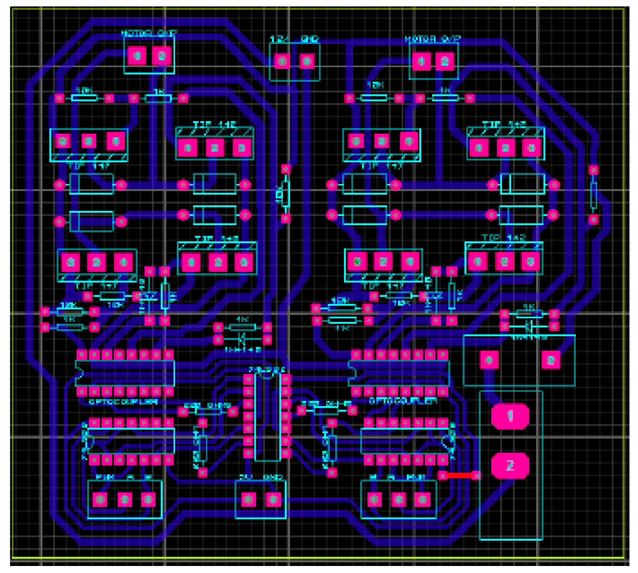
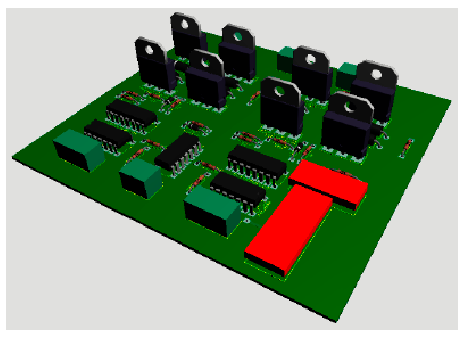
The robot’s movement is controlled by an H-Bridge made of high-power BJTs. For safety purposes, ‘catch diodes’ and opto-couplers are used, which keeps the controller safe from any back EMF effect. The PCB layout of the H-bridge is shown in
Figure 11, and 3D layout is in
Figure 12.
This project consists of a mini-IP camera having a built-in Wi-Fi chip to capture the video and transmit it to the personal computer in 1080p resolution. This camera is operated with a 3.7 V Ni battery. The battery and camera module are shown in
Figure 13.
The main microcontroller used in this project is an Atmel Cortex M3 installed on the robot. This microcontroller has a processing speed of 32-bit/. It controls the movement of the robot and turret and also communicates wirelessly through the NRF module with the PC, where image processing is performed. Upon reception of the command, it will execute the laser targeting. Atmel cortex M3 can be seen in
Figure 14.
2.1.3. Design Parameters and Mathematics
Design parameters and calculations will be categorized into 3 categories, i.e., base frame, load calculation, and motor selection according to load.
Base Frame
- ◦
Length: 38 cm
- ◦
Width: 28 cm
- ◦
Thickness: 0.3 cm
Approximate Load
- ◦
Atmel Cortex-M3 = 80 g
- ◦
NRF = 90 g
- ◦
Camera chip = 150 g
- ◦
Battery = 500 g
- ◦
Servo motors = 100 g
- ◦
Brackets = 100 g
- ◦
Laser module chip = 300 g
- ◦
Gears = 200 g
- ◦
Bearings = 600 g
- ◦
Base = 1800 g
- ◦
Motors = 600 g
- ◦
Others = 250–450 g
(Total = 4970 g approximate loads considering tolerance 5200 g)
Given that the radius of the gear wheel is 2.4 cm and required translational speed is 40 cm/s–60 cm/s.
2.2. Facial Recognition
2.2.1. Dataset
A dataset is created by determining the face in the image captured. A binary number is obtained by labeling each image pixel using the LBP operator to determine the exact facial features and their location in the image. Each image pixel is labeled by a threshold of 3 × 3 neighborhood from the center value [
15]. The value of each label can be represented as
where the gray value of each equally spaced pixel around the central pixel is represented by
and the gray value of each central pixel is
With the help of this LBP operator, only that part of the image is cropped and saved in the dataset, which has facial features; the rest of the image is excluded.
2.2.2. Recognizer
Comparison between the stored dataset and the current facial pattern from the live video is determined by calculating the dissimilarity between the current histogram
ζ created based on the face in the live video and the one created by the facial patterns stored in the dataset
ψ. This dissimilarity is represented in terms of the square of the distance
[
15]:
where the feature vector is represented by “l”. The psedudo code of intelligent LBPH algorithm in combination with Haar-cascade classifiers in provided next (Algorithm 1).
| Algorithm 1: Pseudo Code |
| 1: | |
| 2: | START |
| 3: | preprocessing; |
| 4: | Import numpy |
| 5: | Import opencv |
| 6: | Import sys |
| 7: | Face_cascade = Import Cascade Classifier |
| 8: | Cam = Initialize the Camera and start live video |
| 9: | Id = Enter ID for the Target |
| 10: | initialization; |
| 11: | Sample_number = 0 |
| 12: | IF not cam: |
| 13: | Print (“Error Opening Capture Device”) |
| 14: | Sys.exit(1) |
| 15: | ENDIF |
| 16: | While: |
| 17: | Ret, Img = Read the camera |
| 18: | Img = Flip the image |
| 19: | Gray = Gray scale conversion of Img |
| 20: | Faces = Conversion into multi grayscale |
| 21: | For (x, y, w, h) in faces: |
| 22: | Draw rectangle for (x,y) faces |
| 23: | Roi_gray = calculating region of interest for face |
| 24: | Roi_color = cropping the region of interest for face |
| 25: | Sample_number = sample_number + 1 |
| 26: | Save cropped image with sample ID and sample number |
| 27: | Show the sample images saved in directory |
| 28: | IF enter Q then: |
| 29: | break |
| 30: | Elif Sample_number > 49 then: |
| 31: | break |
| 32: | Release the Camera |
| 33: | Close live video |
| 34: | END |
| 35: | |
| 36: | START |
| 37: | import os |
| 38: | import opencv |
| 39: | import numpy |
| 40: | Import img from PIL |
| 41: | |
| 42: | Recognizer = Create LBPH Recognizer |
| 43: | detector = Importing cascade classifier |
| 44: | path = Setting path to dataset directory |
| 45: | Def Get Images from ID path |
| 46: | imagePaths = setting paths to images |
| 47: | Faces = [] |
| 48: | IDs = [] |
| 49: | For imagePath in imagePaths: |
| 50: | faceImg = Open images from path |
| 51: | faceNp = Converting images into array of numbers |
| 52: | ID = Getting ID from the sample image name |
| 53: | faces = Apply detector on faceNp array |
| 54: | |
| 55: | For (x, y, w, h) in faces: |
| 56: | Appending faceNp array to determine the size of sample images |
| 57: | Appending ID of the sample images |
| 58: | Output Faces, IDs |
| 59: | |
| 60: | faces, IDs = getImagesWithId(‘DataSet’) |
| 61: | Train LBPH Recognizer for Face array |
| 62: | Save the training file in a desired path |
| 63: | Close all windows |
| 64: | END |
| 65: | |
| 66: | START |
| 67: | Import os |
| 68: | Import numpy |
| 69: | Import opencv |
| 70: | Import sys |
| 71: | Import serial |
| 72: | Import time |
| 73: | Import struct |
| 74: | Import urllib3 |
| 75: | |
| 76: | Print “Connecting to Arduino” |
| 77: | arduino = Set serial port to general COM with baudrate 9600 |
| 78: | Sleep time for 3 s |
| 79: | Print message “Connection Established Successfully” |
| 80: | recognizer = Applying LBPH Recognizer |
| 81: | Read the Training file stored in directory |
| 82: | cascadePath = Import face cascades |
| 83: | faceCascade = Apply classifier to cascadePath |
| 84: | font = Setup Hershey_simplex font |
| 85: | cam = Start live video from Cam 1 |
| 86: | IF not cam: |
| 87: | Print message “Error Opening Capture Device” |
| 88: | sys.exit(1) |
| 89: | |
| 90: | while True: |
| 91: | ret, img = Read from Camera |
| 92: | img = Flip the images taken from live video |
| 93: | gray = Conversion of colored pic to gray scale |
| 94: | faces = Setting up Multiscale gray scale |
| 95: | For (x, y, w, h) in faces: |
| 96: | Draw rectangle around face in live video |
| 97: | Id, confidence = Identification of person from ID through dataset |
| 98: | IF (Id == 1): |
| 99: | Id = Extract the name from ID and display in live video |
| 100: | x1 = Calculate initial horizontal coordinate of face position |
| 101: | y1 = Calculate initial vertical coordinate of face position |
| 102: | x2 = Calculate horizontal angle of face position |
| 103: | y2 = Calculate vertical angle of face position |
| 104: | Send Center coordinates to Arduino |
| 105: | Print message “Id =” |
| 106: | Print (Id) |
| 107: | Print message “Horizontal Angle =” |
| 108: | Print (x1) |
| 109: | Print message “Vertical Angle =” |
| 110: | Print (y1) |
| 111: | ELSE: |
| 112: | Id = Display Unknown Person |
| 113: | Draw rectangle around face |
| 114: | Write text below rectangle |
| 115: | Show images from live video |
| 116: | k = Wait 30 s and check the entry key |
| 117: | If k == 27 then |
| 118: | Break |
| 119: | Release Camera |
| 120: | Close all windows |
| 121: | END |
2.3. Developed GUI
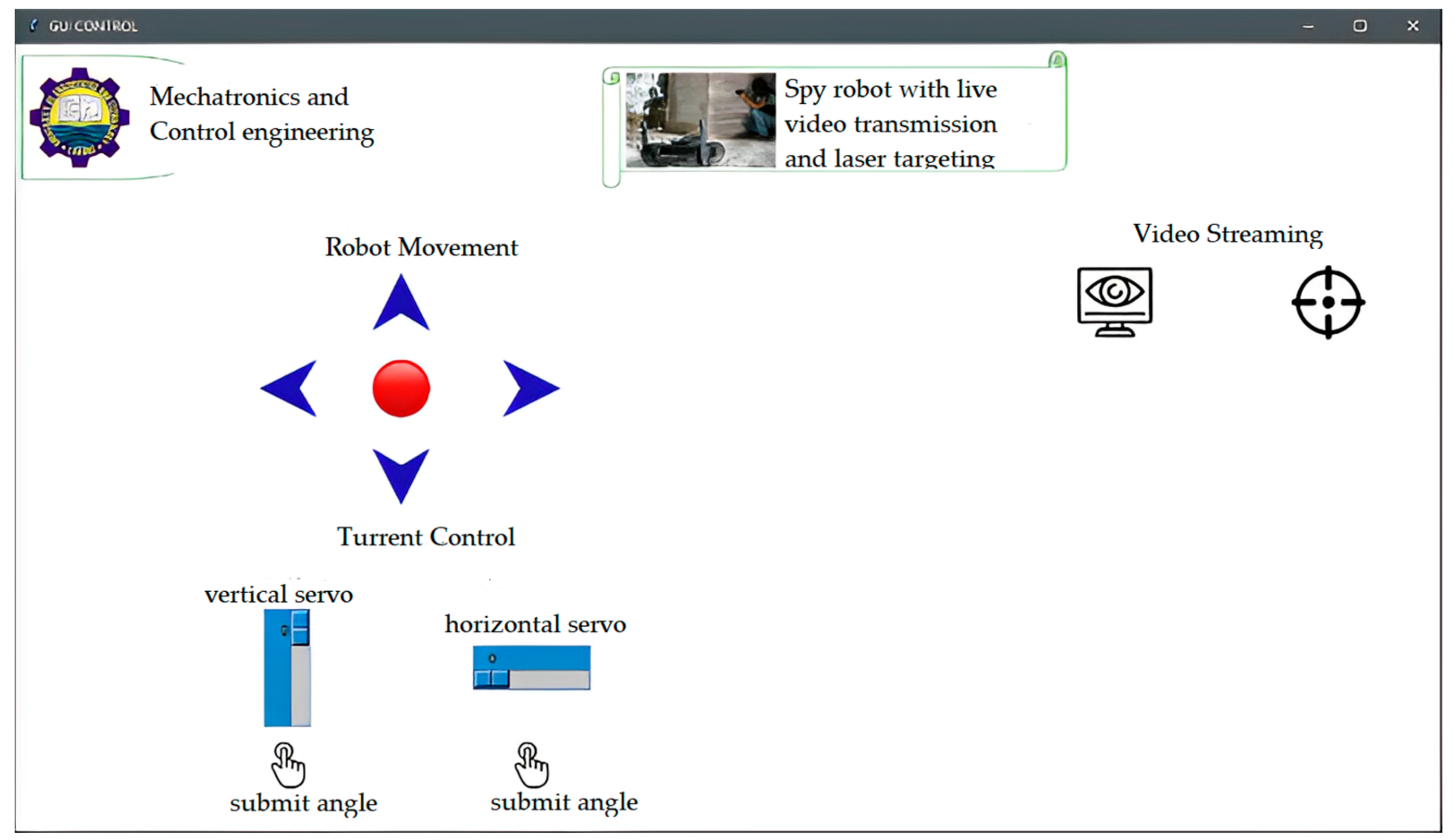
GUI interface of the robot has 5 buttons, i.e., Forward, Left, Right, Back, and Stop, to control the direction of the robot, and there are two other buttons. One button starts the video streaming and the facial recognition, and the 2nd is for laser targeting. Graphical interface can be seen below in
Figure 15.
There are two sliders, one is used to control the horizontal position of the turret, and the 2nd slider is used to control the vertical position of the turret manually; while in facial recognition mode, the turret automatically tracks the assigned target and changes its position according to the frame of reference.
2.4. Radio Controller
The control systems [
25,
26,
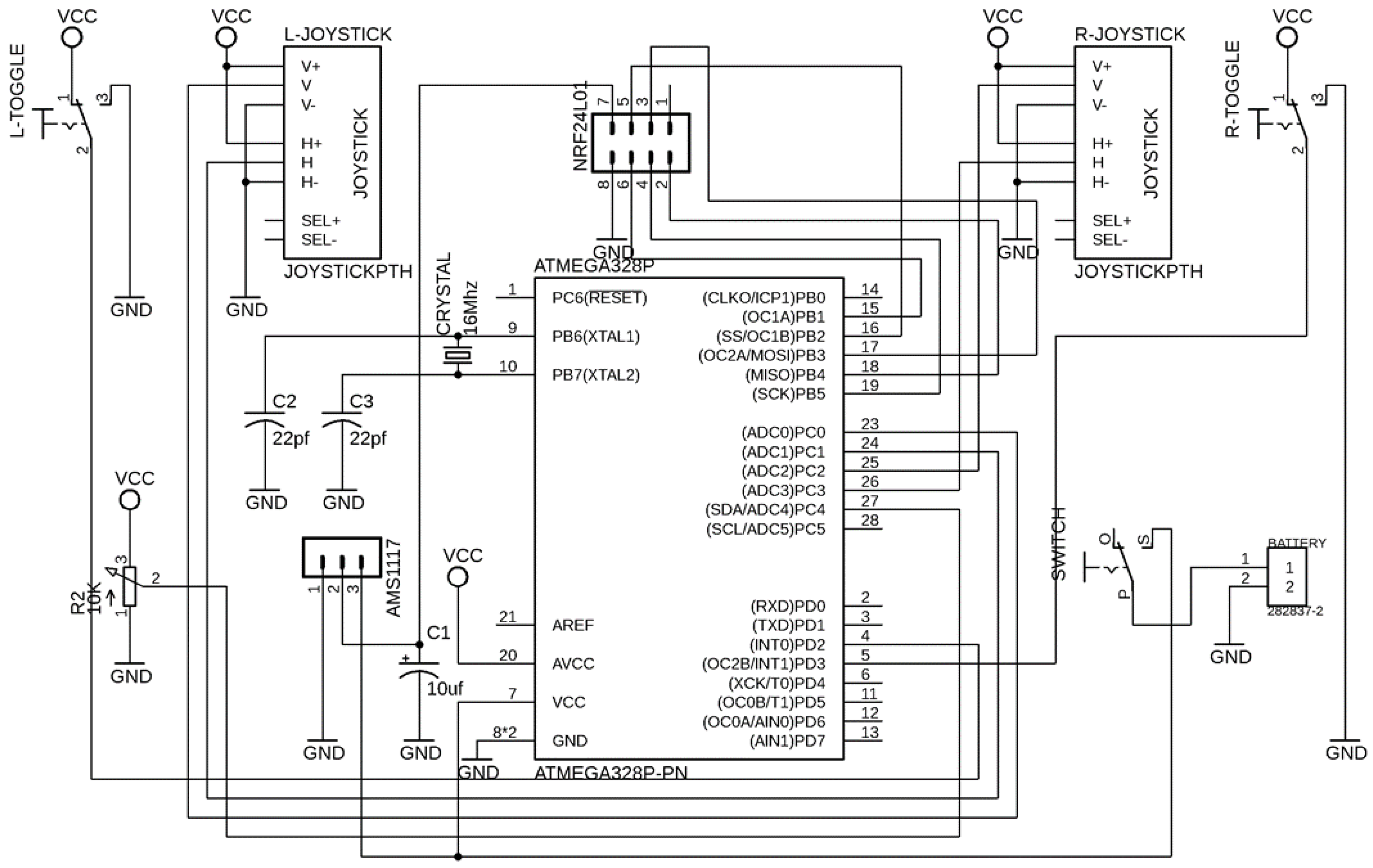
27] are necessary to achieve the desired response. The designed radio controller for the robot operates on a 2.4 GHz frequency. The schemetic of radio controller is shown in
Figure 16 and PCB layout of this controller is shown in
Figure 17. The data transmission rate varies from 200 Kb/s–2 Mb/s, which affects the range of control. In total, 7 channels can transmit the data at the same time. However, these channels are limited due to microcontroller pins.
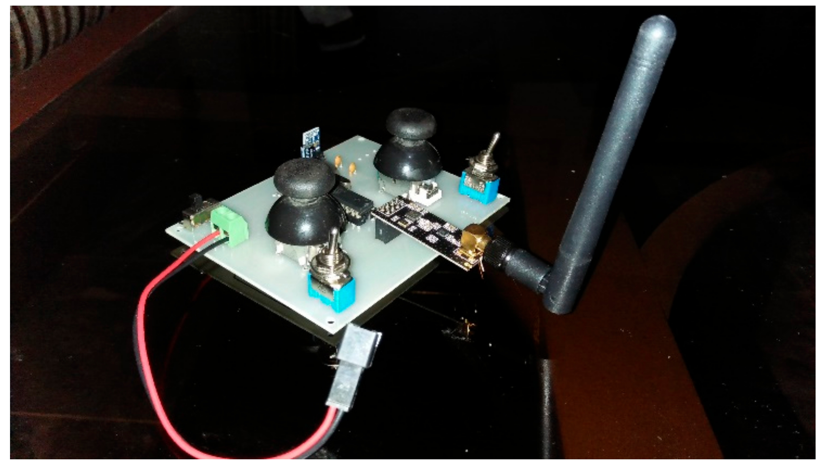
In this radio controller, almost 32 channels can be controlled simultaneously. In total, 7 tracks of the radio controller include 5 analog channels, of which 2 joysticks have 4 analog channels, two analog channels control robot direction, and the other two control turret position. There are 2 digital channels. One of them is used to fire the laser gun, while the rest of one digital channel, and the analog channel, is spared for more features to be added. Schematic, as well as the PCBA of the radio controller, has been designed in Eagle CAD platform. The microcontroller used in the radio controller is Atmega328p; it has an 8-bit processing speed and consists of multiple digital and analog input pins. The analog output can also be generated using pulse width modulation in programming. Programming of the radio controller has been done in the Arduino platform. Hardware assembly of the radio controller is shown in
Figure 18.
3. Results and Discussion
Concerning RF communication, it is concluded that this UGV can be controlled wirelessly over a range of 1100 m with a clear line of sight, maintaining a data transfer rate of 200 Kb/s–2 Mb/s; if the line of sight is not cleared, then its range of operation is limited to 700–800 m. The air data rates for the NRF24L01+ that we used range from 250 Kbps to 2 MB/s. A 250 Kb/s data rate was chosen since it uses less power and has a greater range of more than 1 km, extending the battery life. Even though other wireless transmitters do not have many independent, bi-directional channels, the NRF24L01+ was chosen as the preferred option because it has 32 channels. As far as facial recognition is concerned, it takes 2–3 s to detect the target data already stored in our database.
There is an additional feature of making a dataset of an enemy target right on the spot and storing its images in our cloud system located in headquarters. It is helpful if a liable threat is detected during live video transmission. The limitation of facial localization is that it cannot track the movement of multiple targets and send the coordinates to our mobile robot. Facial recognition in live video transmission can be seen below in
Figure 19.
Figure 19 shows hundred percent accuracy in a real-time environment. If the sample photographs and the real-time were identical, we could attain 100%, which is unrealistic because one person can appear in different ways; for example, the beard is heavy in the sample, but not in real-time. In such circumstances, the similarity factor would vary. In conclusion, we achieved 99.8% accuracy in our experiment.
When comparing the results in accordance with the datasheet, data packet loss at each stage and the distance-power curve for radio transmitters were taken into account. Higher power usage was also evident in the range comparison. In conclusion, we achieved improved facial recognition accuracy even with low resolution due to high sampling in the database, stable long range of more than 1 km with almost negligible data loss, and an enormous number of independent bi-directional communication channels.


