Abstract
To achieve the maximum power from wind in variable-speed regions of wind turbines (WTs), a suitable control signal should be applied to the pitch angle of the blades. However, the available uncertainty in the modeling of WTs complicates calculations of these signals. To cope with this problem, an optimal controller is suitable, such as particle swarm optimization (PSO). To improve the performance of the controller, fractional order PSO (FPSO) is proposed and implemented. In order to construct this approach for a two-mass WT, we propose a new state feedback, which was first applied to the turbine. The idea behind this state feedback was based on the Taylor series. Then, a linear model with uncertainty was obtained with a new input control signal. Thereafter, the conventional PSO (CPSO) and FPSO were used as optimal controllers for the resulting linear model. Finally, a comparison was performed between CPSO and FPSO and the fuzzy Takagi–Sugeno–Kang (TSK) inference system. The provided comparison demonstrates the advantages of the Taylor series with combination to these controllers. Notably, without the state feedback, CPSO, FPSO, and TSK fuzzy systems cannot stabilize WTs in tracking the desired trajectory.
Keywords:
wind turbine; pitch angle control; fractional particle swarm optimization; fuzzy inference system; Taylor series MSC:
93D15
1. Introduction
Solar or wind, as clean renewable viable energies, are accessible worldwide and are clean. However, due to economic reasons, the use of wind energy and wind turbines (WTs) is popular. There are two kinds of WT, fixed speed WTs (FWTs) [1,2] and variable-speed WTs (VWTs) [3]. It is not capable for FWTs to work such that the maximum power of wind can be harnessed [4]. Therefore, VWTs have recently been developed and constructed. To capture the maximum power of wind in VWTs, its operation regions are divided into four important sections using cut-out, rated, and cut-in boundaries [5]. Below the cut-out wind speed, VWTs will be shut down, to balance economic performance between the cut-out and rated wind speeds by controlling the generator torque [5]. Moreover, between the rated and cut-in boundaries of wind speeds, the pitch angle of turbine blades is used as the input control [6]. Finally, above the cut-in boundary, the VWT will be shut down again to protect it from fatigue damage [7].
On the other hand, mechanical stresses are another important challenge, which require powerful optimal or adaptive approaches to protect WTs [7]. Therefore, some pitch angle controllers have been proposed for WT blades between cut-out and rated wind speeds [6,7,8,9,10,11,12,13,14]. In [6], a digital controller was designed; classical controllers such as PID (proportional–integral–derivative) are proposed in [7,8]; a PID controller with an adaptive self-tuning regulator (STR) was constructed in [9]; a gain-scheduled PID controller was designed in [10]; a PI controller scheme is shown in [11]; and a combination of adaptive and PI controllers is presented in [12]. Some simple nonlinear feedback controllers are proposed in [13,14]. Finally, to improve the performance of WTs, variable frequency converter controls to regulate the rotor speed were also used in [3,15].
Among these approaches, fractional controllers can have better performance [16,17] because they can precisely describe the behavior of many dynamical systems in physical, mathematical, and engineering fields [18,19,20]. Hence, many studies have focused on fractional subjects to develop their theories [21,22]. Therefore, the fractional calculations have progressed in various phenomena due to their applications in dynamic systems [17].
In the other hand, particle swarm optimization (PSO) is a power tool for optimization [23] and controllers [24]. Therefore, based on the advanced properties of fractional calculus and PSO, we improved the performance of conventional PSO (CPSO) using a combination of fractional and PSO. The proposed approach is fractional PSO (FPSO), and was applied to WTs for pitch angle control. Initially, state feedback was applied to the WT model; then, FPSO forced the WT rotor angular velocity to track its reference while the pitch angle of the blades was regulated. To demonstrate the advanced performance of FPSO, comparison was performed with CPSO and the Takagi–Sugeno–Kang (TSK) fuzzy system with similar parameters [25].
Hence, the proposed controller is demonstrated in five sections. First, the WT model and their subsystems are explained in Section 2. Then, the controller details, consisting of state feedback, with reference to rotor angular velocity, PSO, and TSK system, are provided in Section 3. The simulation results and comparisons of FPSO, CPSO, and TSK systems are presented in Section 4. Section 5 presents the conclusion.
2. Wind Turbine (WT) Model
The generator and drivetrain are two WT subsystems, their electrical and mechanical sections, respectively [16]. Other important subsystem of a WT is the aerodynamic section [16]. These subsystems are depicted in Figure 1.

Figure 1.
The WT subsystems.
2.1. The Aerodynamic Subsystem
Considering a WT with blade length , power coefficient , the captured power can calculated using the following equation:
where is the air density and is the wind speed, which are dependent on environment conditions. The power coefficient is dependent on the tip speed ratio, , and the pitch blades, [5], which are defined as follows:
2.2. The Drivetrain Subsystem
The two-mass mechanical drivetrain, which shows the transient response and steady-state response in the presence of the controller, is described by the following equations and is depicted in Figure 2 [26].
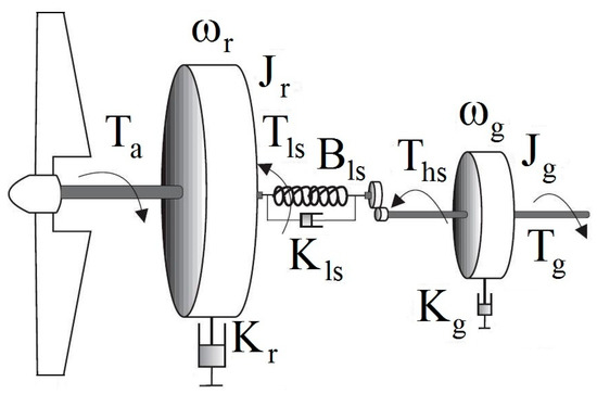
Figure 2.
The drivetrain structure.
In Figure 2, and are angular velocity, and are inertia, and are the external dapping, and are the torque output, on the generator and rotor side, respectively, and finally, and are the braking torque in the high-speed and low-speed shaft. The ratio of gearbox is defined as:
Using the second part of Equation (6) results in:
or:
Finally, adding this equation to the first part of Equation (6) results in [5]:
Such that and . In fact, all the parameters are transferred to a low-speed shaft [5].
2.3. The Generator Subsystem
The , i.e., the output torque of the generator, can be modeled using the first-order dynamic, where is the reference torque and is the generator time constant.
We focused on pitch control; thus, the generator torque reference was set as . Moreover, the produced output power delivered to the grid can be written as , where the efficiency of the generator is .
3. The Optimal Controller Design
In this section, we first used state feedback and then calculated the desired rotor angular velocity. The CPSO and FPSO optimal controllers are also described.
3.1. State Feedback
Initially, we calculated the derivative of the power coefficient of Equation (3) with respect to the pitch angle of the blades.
Therefore, the Taylor series of Equation (5) around its optimal operating points and would be:
where is used to denote higher-order terms; thus:
Due to the convergence of the Taylor series around the operating points, the unknown uncertainty is bounded, i.e., . Then, the following state feedback with the new input signal, , and the arbitrary parameter, , can be used.
Then, system Equation (14) can be rewritten as follows:
In which is an unknown uncertain function. We aimed to design an optimal approach such that in this linear system, the rotor angular velocity, , tracked the desired signal, .
3.2. Reference of Rotor Angular Velocity
As mentioned in the Introduction and based on Figure 3, the VWT operation modes were divided into four regions using wind speed boundaries of cut-in, rated, and cut-out. The critical point is the rated wind speed, such that below this point, the pitch of turbine blades is fixed and generator torque is controlled; hence, the rotor speed is increased to have the maximum of power coefficient. Moreover, above the rated wind speed, the generator reference torque is fixed and is set to its rated value. In this region, the pitch angle would be increased to reduce the rotor speed. Finally, out of the cut-in and cut-out wind speeds, the turbine would be shut down due to the economic criterion and fatigue damages, respectively [5].
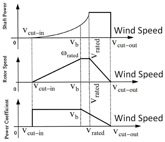
Figure 3.
Operation regions of the VWT.
In this study, we focused on the pitch angle control in region three, whereas the rotor angular velocity should be reduced with the increased of wind speed. Therefore, the reference of rotor angular velocity is as follows:
Based on Equation (2), one can conclude that:
3.3. Particle Swarm Optimization (PSO) and Controller Structure
According to the previous sections, the aim was to determine the angular velocity of the rotor, i.e., tracks the desired trajectory, . To this end, the error, , is applied to the PSO. PSO is applied to calculate the input control signal, , in Equation (16), while the error signal, , converges to zero. In CPSO, the velocity of each particle is updated as follows [23]:
where is the number of particles, is the velocity of each particle, and are uniformly random functions between 0 and 1, is the best position of each particle, is the global best position between all of the particles, is the current position of the each particle, and coefficients and are constant numbers. Then, the position of any particle is updated as follows [23]:
There are several definitions for fractional differentiations and integrations, such as Grünwald–Letnikov, Riemann–Liouville, and Caputo formulae [27]. Among them, the Caputo method is popular because initial conditions are considered [17,27]; thus, the Caputo definition was used in this study.
Definition 1.
Caputo q-order integration and the differentiation of variablewith respect to time,, is defined as follows [27]:
Remark 1.
In this study, we considered the zero initial condition, i.e.,
. Moreover, for simplicity, subscript was also eliminated; hence, we use
instead of
and
instead of
.
To improve the performance of the CPSO, we propose FPSO, as follows:
For a valid comparison, both CPSO and FPSO were implemented. Therefore, the implemented diagram of the proposed approach is illustrated in Figure 4. From this figure, one can see the combination of two feedbacks for nonlinear systems of Figure 1 and Figure 2. The first state feedback of Equation (15) is based on the theory of the Taylor series with a new input control signal, , to obtain a linear system, as in Equation (16). Then, in the second feedback, FPSO or CPSO were applied to this linear system in order to minimize the error signal. Moreover, we used the fuzzy TSK systems.
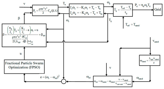
Figure 4.
The implemented structure of the proposed controller.
3.4. Takagi–Sugeno–Kang (TSK) Controller Structure
The structure of proposed TSK controller is shown in Figure 4, with two inputs and its derivative and one output . For each input and output, five triangular membership functions are defined as negative-large (NL), negative-small (NS), zero (Z), positive-small (PS), and positive-large (PL). The range of inputs was set between −2 and +2, and the range of output was also set to between −200 and 200. Therefore, 25 rules with the aggregation defuzzification were used.
4. Simulations Results
We used the two-mass 5 MW, VWT in National Renewable Energy Laboratory (NREL) located at Colorado, with the aerodynamic parameters in Table 1 and drivetrain parameters in Table 2 [28].

Table 1.
The aerodynamic parameters of VWT.

Table 2.
The mechanical drivetrain parameters of VWTs.
For a reliable comparison, all of the simulations were performed using MATLAB software with a sample time of 0.01. The wind speed is shown in Figure 5, with a mean value 16 and maximum disturbance of 5. Notably, this is between 11.4 and 25, i.e., in region 3: . In addition, the initial value for the rotor angular velocity is set to 3, i.e., , and the feedback parameter is set as . Moreover, Figure 6 shows the reference of rotor speed in region 3 denoted by Equation (17).
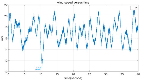
Figure 5.
The profile of time series wind speed.
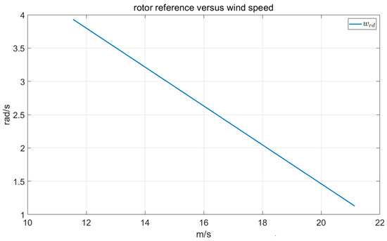
Figure 6.
Reference of the rotor speed in region 3 of VWTs.
Example 1.
The CPSO approach.
As the first result, simulations of the CPSO in Equation (19) are shown in Figure 7, Figure 8, Figure 9 and Figure 10. The parameters of the PSO are , with 20 particles and 4000 iterations.
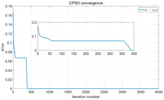
Figure 7.
Convergence of the CPSO.
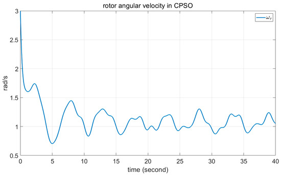
Figure 8.
Angular velocity of the rotor in CPSO.
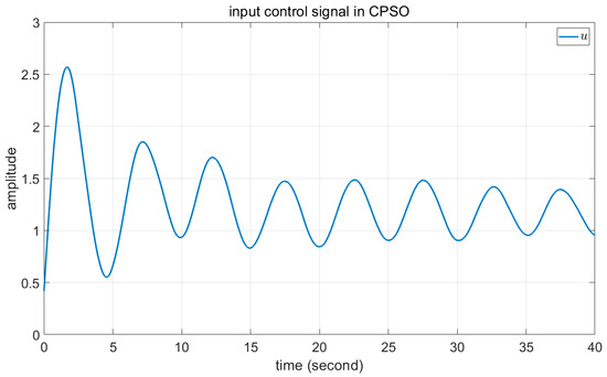
Figure 9.
The input control signal of state feedback in CPSO.
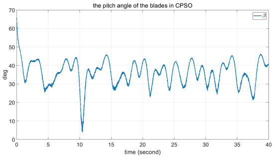
Figure 10.
The angle of blades in CPSO.
Example 2.
The proposed FPSO approach.
As the second result, simulation of the FPSO in Equation (21) is shown in Figure 11, Figure 12, Figure 13 and Figure 14 with the fraction order and the same parameters of example 1, i.e., with 20 particles and 4000 iterations and .
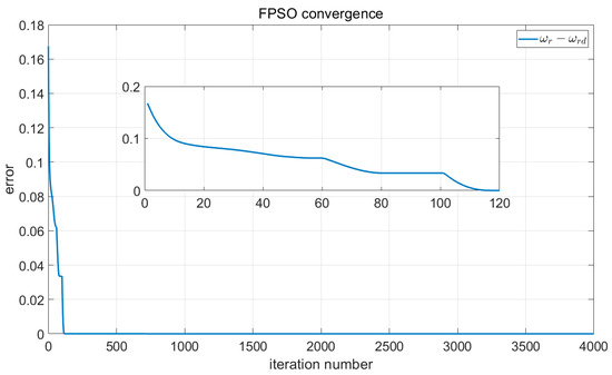
Figure 11.
Convergence of the FPSO.
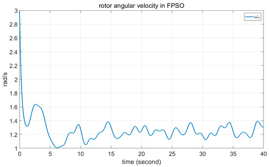
Figure 12.
Angular velocity of the rotor in FPSO.
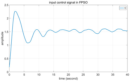
Figure 13.
The input control signal of state feedback in FPSO.
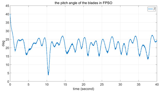
Figure 14.
The angle of blades in FPSO.
Example 3.
The proposed fuzzy TSK approach.
As the third example, the results of the fuzzy TSK inference system are shown in Figure 15, Figure 16, Figure 17 and Figure 18, similar to previous examples.
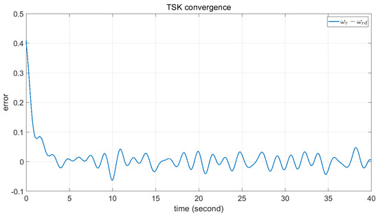
Figure 15.
Convergence of the fuzzy TSK.
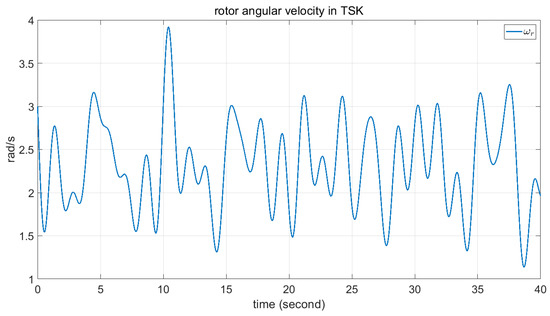
Figure 16.
Angular velocity of the rotor in fuzzy TSK.
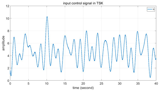
Figure 17.
The input control signal of state feedback in fuzzy TSK.
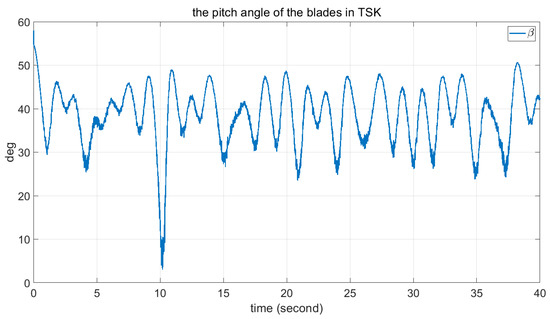
Figure 18.
The angle of blades in fuzzy TSK.
Comparison Results. FPSO, CPSO, and proposed TSK approach.
Comparisons of these figures demonstrate the good performance of the proposed FPSO. Figure 7 and Figure 11 show the convergence of the error signal. These figures indicate the faster convergence of FPSO. However, as shown in Figure 15, the convergence error of TSK seems to be very good. Comparison of Figure 8, Figure 12 and Figure 16 shows the smaller variation in rotor angular velocity in FPSO. Moreover, as Figure 9, Figure 13 and Figure 17 show, the input control signal of the state feedback in FPSO is smoother. In addition, Figure 10, Figure 14 and Figure 18 show the pitch angle of WT blades. The variation in pitch in FPSO is smaller in comparison with the two other approaches. These are cause low mechanical stress to the drivetrain part in FPSO. Thereafter, when the wind speed is decreased to about 10.4 s, the pitch angles are converged to their optimal value, . Notably, when the wind speed is decreased below , the pitch angles are fixed to the optimal value and the WT torque would be controlled. Finally, in Figure 19 and Figure 20, the time for one rotation and its mean value is also depicted. From Figure 19, one can see the low speed variation in FPSO and very high speed variation in TSK controller. Figure 20 shows the closeness of FPSO and CPSO for one rotation, but the fuzzy TSK system has very low speed. As the final result, one can see the simplicity and good performance of FPSO in concept and real-world implementation with respect to the CPSO and TSK inference systems.
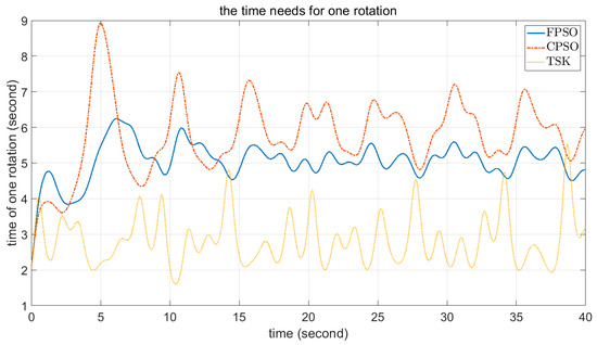
Figure 19.
The time for one rotation in FPSO, CPSO, and fuzzy TSK.
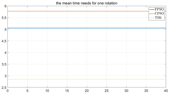
Figure 20.
The mean time for one rotation in FPSO, CPSO, and fuzzy TSK.
Remark 2.
Notably, unlike nonlinear systems, in linear systems only one global minimum is available for the error. Therefore, in the absence of the first feedback, the FPSO, CPSO, and TSK cannot converge.
5. Conclusions
In this paper, new issues are presented for the optimal pitch control of variable-speed wind turbines (VWTs). First, a new state feedback approach based on Taylor series was applied to the wind turbine (WT) to obtain a linear model with uncertainty and a new input control signal. Second, particle swarm optimization (PSO) and the fuzzy Takagi–Sugeno–Kang (TSK) system were used to force the rotor angular velocity to track the desired trajectory. Then, the overall closed loop approach was applied to the two-mass 5 MW WT. Finally, comparisons of the conventional PSO (CPSO), fractional PSO (FPSO), and TSK controller were performed using simulation. In the proposed FPSO, the performance of the controller was better. To show the superiority of the FPSO, the same parameters were used in all three approaches. Moreover, the design procedures show the simplicity of the FPSO in concept and in realization
Author Contributions
A.K.-M.: analysis, writing—original draft preparation; O.B.: conceptualization, writing—review and editing. All authors have read and agreed to the published version of the manuscript.
Funding
This study received no external funding.
Institutional Review Board Statement
Not applicable.
Informed Consent Statement
Not applicable.
Data Availability Statement
Not applicable.
Acknowledgments
The authors wish to express their gratitude to the Basque Government, through the project EKOHEGAZ (ELKARTEK KK-2021/00092), to the Diputación Foral de Álava (DFA), through the project CONAVANTER, and to the UPV/EHU, through the project GIU20/063, for supporting this study.
Conflicts of Interest
The authors declare no conflict of interest.
References
- Rahimi, M.; Parniani, M. Dynamic behavior and transient stability analysis of fixed speed wind turbines. Renew. Energy 2009, 34, 2613–2624. [Google Scholar] [CrossRef]
- Sumper, A.; Gomis-Bellmunt, O.; Sudria-Andreu, A.; Villafafila-Robles, R.; Rull-Duran, J. Response of Fixed Speed Wind Turbines to System Frequency Disturbances. IEEE Trans. Power Syst. 2009, 24, 181–192. [Google Scholar] [CrossRef]
- Barambones, O.; Cortajarena, J.A.; Calvo, I.; de Durana, J.M.G.; Alkorta, P.; Karami-Mollaee, A. Variable speed wind turbine control scheme using a robust wind torque estimation. Renew. Energy 2019, 133, 354–366. [Google Scholar] [CrossRef]
- Poultangari, I.; Shahnazi, R.; Sheikhan, M. RBF neural network based PI pitch controller for a class of 5-MW wind turbines using particle swarm optimization algorithm. ISA Trans. 2012, 51, 641–648. [Google Scholar] [CrossRef]
- Karami-Mollaee, A. A new structure of sliding mode observer in dynamic sliding mode control of generator torque wind turbine. J. Mech. Sci. Technol. 2021, 35, 5681–5687. [Google Scholar] [CrossRef]
- Camblong, H. Digital robust control of a variable speed pitch regulated wind turbine for above rated wind speeds. Control Eng. Pr. 2008, 16, 946–958. [Google Scholar] [CrossRef]
- Gao, R.; Gao, Z. Pitch control for wind turbine systems using optimization, estimation and compensation. Renew. Energy 2016, 91, 501–515. [Google Scholar] [CrossRef]
- Yuan, Y.; Chen, X.; Tang, J. Multivariable robust blade pitch control design to reject periodic loads on wind turbines. Renew. Energy 2020, 146, 329–341. [Google Scholar] [CrossRef]
- Hatami, A.; Moetakef-Imani, B. Innovative adaptive pitch control for small wind turbine fatigue load reduction. Mechatronics 2016, 40, 137–145. [Google Scholar] [CrossRef]
- Yuan, Y.; Tang, J. Adaptive pitch control of wind turbine for load mitigation under structural uncertainties. Renew. Energy 2017, 105, 483–494. [Google Scholar] [CrossRef]
- Rahimi, M.; Asadi, M. Control and dynamic response analysis of full converter wind turbines with squirrel cage induction generators considering pitch control and drive train dynamics. Int. J. Electr. Power Energy Syst. 2019, 108, 280–292. [Google Scholar] [CrossRef]
- Lasheen, A.; Elnaggar, M.; Yassin, H. Adaptive control design and implementation for collective pitch in wind energy conversion systems. ISA Trans. 2020, 102, 251–263. [Google Scholar] [CrossRef] [PubMed]
- Boukhezzar, B.; Lupu, L.; Lupu, L.; Hand, M. Multivariable control strategy for variable speed, variable pitch wind turbines. Renew. Energy 2007, 32, 1273–1287. [Google Scholar] [CrossRef]
- Chen, L.; Yang, Y.; Gao, Y.; Gao, Z.; Guo, Y.; Sun, L. A novel real-time feedback pitch angle control system for vertical-axis wind turbines. J. Wind Eng. Ind. Aerodyn. 2019, 195, 104023. [Google Scholar] [CrossRef]
- Barambones, O.; Cortajarena, J.A.; Calvo, I.; de Durana, J.M.G.; Alkorta, P.; Karami-Mollaee, A. Real time observer and control scheme for a wind turbine system based on a high order sliding modes. J. Frankl. Inst. 2021, 358, 5795–5819. [Google Scholar] [CrossRef]
- Asgharnia, A.; Shahnazi, R.; Jamali, A. Performance and robustness of optimal fractional fuzzy PID controllers for pitch control of a wind turbine using chaotic optimization algorithms. ISA Trans. 2018, 79, 27–44. [Google Scholar] [CrossRef]
- Petras, I. Fractional Order Nonlinear Systems; Springer: Berlin/Heidelberg, Germany, 2011. [Google Scholar]
- Kilbsa, A.A.; Srivastava, H.M.; Trujillo, J.J. Theory and Applications of Fractional Differential Equations; Elsevier: New York, NY, USA, 2006. [Google Scholar]
- Podlubny, I. Fractional Differential Equations: An Introduction to Fractional Derivatives, Fractional Differential Equations, to Methods of Their Solution and Some of Their Applications; Academic Press: San Diego, CA, USA, 1998. [Google Scholar]
- Qiu, F.; Liu, Z.; Liu, R.; Quan, X.; Tao, C.; Wang, Y. Fluid flow signals processing based on fractional Fourier transform in a stirred tank reactor. ISA Trans. 2019, 90, 268–277. [Google Scholar] [CrossRef]
- Li, Y.; Chen, Y.; Podlubny, I. Stability of fractional-order nonlinear dynamic systems: Lyapunov direct method and generalized Mittag–Leffler stability. Comput. Math. Appl. 2010, 59, 1810–1821. [Google Scholar] [CrossRef]
- Aguila-Camacho, N.; Duarte-Mermoud, M.A.; Gallegos, J.A. Lyapunov functions for fractional order systems. Commun. Nonlinear Sci. Numer. Simul. 2014, 19, 2951–2957. [Google Scholar] [CrossRef]
- Choi, Y.-P.; Ju, H.; Koo, D. Convergence analysis of Particle Swarm Optimization in one dimension. Appl. Math. Lett. 2023, 137, 108481. [Google Scholar] [CrossRef]
- He, Z.; Liu, T.; Liu, H. Improved particle swarm optimization algorithms for aerodynamic shape optimization of high-speed train. Adv. Eng. Softw. 2022, 173, 103242. [Google Scholar] [CrossRef]
- Jafarzadeh, S.; Fadali, M.S. On the Stability and Control of Continuous-Time TSK Fuzzy Systems. IEEE Trans. Cybern. 2012, 43, 1073–1087. [Google Scholar] [CrossRef] [PubMed]
- Boukhezzar, B.; Siguerdidjane, H. Nonlinear Control of a Variable-Speed Wind Turbine Using a Two-Mass Model. IEEE Trans. Energy Convers. 2010, 26, 149–162. [Google Scholar] [CrossRef]
- Shantanu, D. Functional Fractional Calculus for System Identification and Controls; Springer-Verlag: Berlin/Heidelberg, Germany, 2008. [Google Scholar]
- Bossanyi, E.A.; Wright, A.D.; Fleming, P.A. Controller Field Tests on the NREL CART2 Turbine; No. NREL/TP-5000-49085; National Renewable Energy Lab (NREL): Golden, CO, USA, 2010. [Google Scholar]
Disclaimer/Publisher’s Note: The statements, opinions and data contained in all publications are solely those of the individual author(s) and contributor(s) and not of MDPI and/or the editor(s). MDPI and/or the editor(s) disclaim responsibility for any injury to people or property resulting from any ideas, methods, instructions or products referred to in the content. |
© 2022 by the authors. Licensee MDPI, Basel, Switzerland. This article is an open access article distributed under the terms and conditions of the Creative Commons Attribution (CC BY) license (https://creativecommons.org/licenses/by/4.0/).