Article

Durability Evaluation of Phosphogypsum-Based Cemented Backfill Through Drying-Wetting Cycles

1
School of Resources and Safety Engineering, Central South University, Changsha 410083, Hunan, China
2
Key Laboratory of Rock Mechanics and Geohazards of Zhejiang Province, Shaoxing 312000, Zhejiang, China
*
Author to whom correspondence should be addressed.
Minerals 2019, 9(5), 321; https://doi.org/10.3390/min9050321
Submission received: 28 April 2019 / Revised: 23 May 2019 / Accepted: 24 May 2019 / Published: 26 May 2019

Abstract

:
In this study, the durability of phosphogypsum (PG)-based cemented backfill was investigated by drying-wetting cycles to explore deterioration of its strength and the release of impurities. The leachates in this test were composed of deionized water, 5% Na2SO4 solution, 5% NaCl solution, and a range of sulfuric acid solutions with pH values of 1.5, 3, and 5. After drying-wetting cycles, unconfined compressive strength (UCS), visual deterioration, porosity, microstructure and concentrations of phosphate and fluoride in the leachates were measured. The results showed that both saline and acidic solutions could lead to strength reduction of PG-based cemented backfill under different deterioration mechanisms. The mechanical damage of salinity was caused by micro-cracking and degradation of C–S–H. However, the H+ broke the backfill by dissolving hydration products, leaving the conjunctures between PG particles weakened. Furthermore, the environmental impact was investigated by measuring the concentration of phosphate and fluoride in the leachates. In acidic solutions, the release of phosphate and fluoride was greatly enhanced by H+. Compared to the great strength deterioration in saline leachates, the concentration of phosphate and fluoride were similar to that of deionized water, indicating that saline solutions had little impact on the release of hazardous impurities.

Graphical Abstract

1. Introduction

A large number of cavities can be caused by the extraction of underground phosphate ore resources. Mining and industrial waste are often applied to fill the cavity of mines for the reduction of surface subsidence, increase of resource recovery and minimization of waste pollution [1,2,3,4,5,6]. Phosphogypsum (PG), as the main by-product of the phosphate fertilizer industry, mainly consists of CaSO4·2H2O and some impurities. Previous studies have demonstrated the feasibility of recycling PG as a backfilling aggregate from both an engineering and environmental perspective [7,8]. In the PG-based backfill process, the slurry, consisting of PG, a hydraulic binder and water, has good pumping performance. When a PG-based backfill is refilled into cavities, the hardened structure of the backfill can provide early and cured strength [7,9].
Previous studies concentrate on the effect of raw materials (aggregate, binder, and water) on the cemented backfill process. However, after emplacement, the backfill is probably subject to unfavorable conditions during its long-term underground storage. Studies have shown that cementitious products can be damaged by high levels of salinity and acidity, leading to the expansion, cracking and even fracture of the hardened structure [10,11]. In the cement industry, factors affecting the evolution of mechanical properties have been extensively investigated. Firstly, sulfate attack is considered as an important factor influencing the mechanical performance of cemented materials due to the formation of gypsum and ettringite [11,12,13,14,15]. Expansive ettringite results in volume expansion and eventual cracks [16]. The expansion of secondary products can accelerate deterioration of the structure via penetration of harmful ions through the cracks [13,17]. Besides, chloride can affect the durability of the cement structure by converting hydration products into Friedel’s salt [18,19]. Liu et al. concluded that an increase in chloride concentration has a detrimental influence on the unconfined compressive strength (UCS) of stabilized soil [19]. Furthermore, low pH can affect C–S–H by changing the C/S ratio [20]. Studies have shown that under the action of acid rain, backfill structures may be damaged or even completely collapse due to deterioration of cementitious materials [21]. However, the durability performance of backfill has not been clearly studied under various saline and acidic conditions. The mechanical properties of backfill are closely related to the safety of mining operations. Hence, the mechanical properties of backfill exposed to chemical erosion should be evaluated systematically.
As a typical solidification/stabilization (s/s) process, cemented backfill technology can effectively immobilize the impurities in PG, alleviating environmental pollution [22]. In the cement-based s/s process, chemical adsorption and physical adsorption are primary fixation mechanisms [23]. Chemical adsorption refers to the chemical precipitation of low solubility species, and usually occurs with high pH values [23]. Besides, impurities are physically encapsulated by hydration products, such as C–S–H. Although impurities can be stabilized by cementitious products, it is worth noting that cement-based solidified/stabilized impurities are vulnerable to external physical and chemical degradation processes [24,25]. A previous study has pointed out that high NaCl content can increase the leachability of hazardous components in stabilized soil [19]. Similarly, leaching of toxic impurities from cement-stabilized soil increases noticeably in an acidic environment [25]. However, studies on the leaching of hazardous impurities from PG-based backfill are still limited [7,22]. Therefore, research on the dynamics of impurities in backfill should be conducted under unfavorable conditions.
This study aimed to experimentally analyze the durability and environmental risks of PG-based backfill. Hydro-mechanical fatigue was used to accelerate the aging of cemented PG-based backfill. As a common method for durability analysis, a drying-wetting test was conducted in this study. Changes in the mechanical strength and pollutant contents in leachates were the main research themes. To this end, PG-based backfill specimens with a curing age of 120 d were exposed to different solutions (deionized water, 5% Na2SO4 solution, 5% NaCl solution, and a range of acidic solutions with pH values of 1.5, 3, and 5). Samples were then taken after 1, 3, 5, 10, 15, 21 and 30 drying-wetting cycles. Then, the physical, mechanical and microstructural properties were evaluated, including the UCS, morphology, mass, porosity, and microstructure. Simultaneously, the pH fluctuation and the concentration of phosphate and fluoride in the leachates were measured and analyzed.

2. Materials and methods

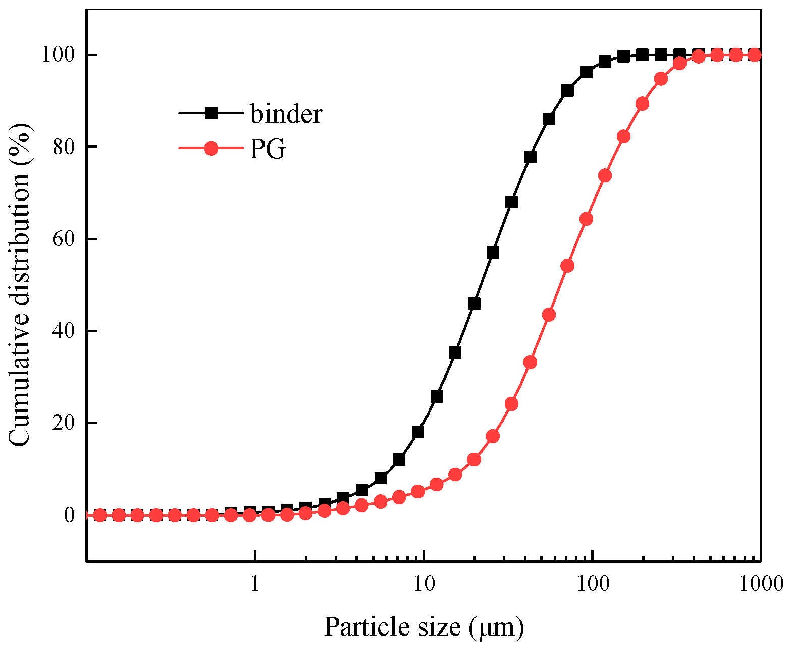
2.1. Raw Material and the Preparation of Backfill Specimens

The experimental PG and binder were purchased from Guizhou Kailin (Group) Co., Ltd., Guiyang, China. The composite binder was produced in mines by mixing and grinding yellow phosphorous slag, calcareous material and cement clinker at a ratio of 6:1:3 [26]. The particle size distributions of the PG and binder were determined by using a particle size analyzer (Mastersizer 2000, Malvern, Malvern, UK), the results of which are shown in Figure 1. The coefficient of uniformity (Cu) and coefficient of curvature (Cc) were used to assess the distribution of particle size in the PG, as shown in Table 1. When PG is used as an aggregate of backfill, the smaller particle size of PG may result in lower strength than typical mine backfill [8]. The specific gravity values of the PG and binder used in this study were 2.35 and 3.21, respectively. The chemical compositions of the PG and binder were measured by X-ray fluorescence (S4 Pioneer, Bruker, Germany), with the results shown in Table 1.
PG, binder and deionized water (at a ratio of 4:1:5 by weight fraction) were mixed at a rotating speed of 200 rpm for 30 min. The backfill slurry had a solid concentration of 50% and a binder dosage of 20%. Compared to the 3~7% of binder used for common cemented paste backfill [7], a high binder percentage was adopted in this study (20%), which was rationalized as follows: Firstly, the high content of acid and sulfate in the PG could have led to a higher demand for binder. Secondly, a reduction in the strength of the cemented materials could have resulted from a lower specific area and lower hydraulic activity of the binder, and poor design, etc. Therefore, a high binder content was adopted in this study to ensure the performance of the PG-based backfill. The apparent viscosity of the slurry was 460 mPa·s, measured by a digital viscometer (NDJ-9S, Fangrui, China). Then, the homogeneous backfill slurry was cast into a plastic mold of dimensions 40 mm × 40 mm × 40 mm. After the initial setting, specimens were coded and placed in a chamber at a temperature of 20 ± 1 °C and a humidity of 95 ± 1%.

2.2. Drying-Wetting Test

A drying-wetting test was adopted to accelerate the deterioration of the PG-based backfill specimens. To reduce the hydration effect on degradation, the drying-wetting test was conducted after 120 d of curing, as shown in Figure 2. Extremely high salinity and acidity were chosen to accelerate the degradation process. Therefore, deionized water, 5% Na2SO4 solution, 5% NaCl solution, and three dilute sulfuric acid solutions with pH values of 1.5, 3, and 5 were used as exposure solutions in this study.
The drying-wetting test performed in this study was in accordance with the recommended method [11,27,28]. Firstly, the PG-based backfill specimens were dried in an oven at 40 °C for 48 h. Secondly, the specimens were submerged in different exposure solutions with a liquid/solid ratio of 5:1 for 24 h at an environment temperature of 20 °C. The specimens were then exposed to 1, 3, 5, 10, 15, 21 and 30 drying-wetting cycles, with the leachate sampled after the specified number of cycles and filtered (0.22 μm) for subsequent chemical analysis.

2.3. UCS Tests

A UCS test is a convenient method for monitoring the quality of backfill [29]. As such, the UCS of the specimens with 1, 3, 6, 10, 15, 21 and 30 drying-wetting cycles was measured. A rigid hydraulic pressure servo machine of 10 kN loading capability (WHY200/10, Hualong, Shanghai, China) was used to test the UCS of the specimens at a constant displacement rate of 0.1 mm/min. To avoid randomness and contingency in the test data, each test was performed three times and the mean values obtained for subsequent analysis. According to the mine operators of Guizhou Kailin (Group) Co., Ltd., the strength of PG-based backfill should be more than 1.0 MPa to satisfy the needs of safe mining operations.

2.4. Chemical Analysis

The pH values of leachates were measured using a pH meter (STARTER300, Ohaus, Parsippany, NJ, America). The concentration of F was measured by a fluorine ion-selective electrode (PF-1-01, Leici, Shanghai, China). The concentrations of SO42– and dissolved PO43– were tested via a spectrophotometer (UV1800, Shimadzu, Kyoto, Japan). Specifically, barium chromate spectrophotometry was employed to evaluate SO42– concentration in the leachates, while the concentration of dissolved PO43– was determined by ammonium molybdate tetrahydrate spectrophotometry.

2.5. Porosity Measurement

Volume accuracy of the specimen is usually required in typical methods of porosity measurement [30]. However, due to spalling on the surface of specimens, volume testing may be inaccurate and result in measurement errors of the total porosity. Therefore, the porosity change was evaluated as follows:
p = m n s m n d m n s × 100 % ,
where p was the porosity of the specimen; m n s was the saturated mass of the specimen after n cycles; and m n d was the dry mass of the specimens after n cycles. Mass changes in the specimens were measured before and after treatment with the exposure solutions by electronic balance with a capacity of 2 kg and an accuracy of 0.01 g.

2.6. Microstructural Studies

Scanning electron microscopy (SEM) and energy dispersive spectrometry (EDS) were conducted to evaluate the microstructural development of the PG-based cemented backfill using the HELIOS NamoLab 600i (FEI, Lake Oswego, America). To prevent further hydration, fractured pieces of PG-based backfill specimens were immediately soaked in an ethanol solution after UCS tests [7]. Prior to the SEM analysis, fractured pieces were dried in an oven at 40 °C. Owing to their poor conductivity, broken specimens were covered with a layer of gold coating in a vacuum to meet the inspection requirements. SEM and EDS analyses were operated at a magnification factor of 2500, an accelerating voltage of 10.00 kV, and a working distance of 6.0 mm.

3. Results and Discussion

3.1. Properties of Backfill Exposed to Chemical Solutions

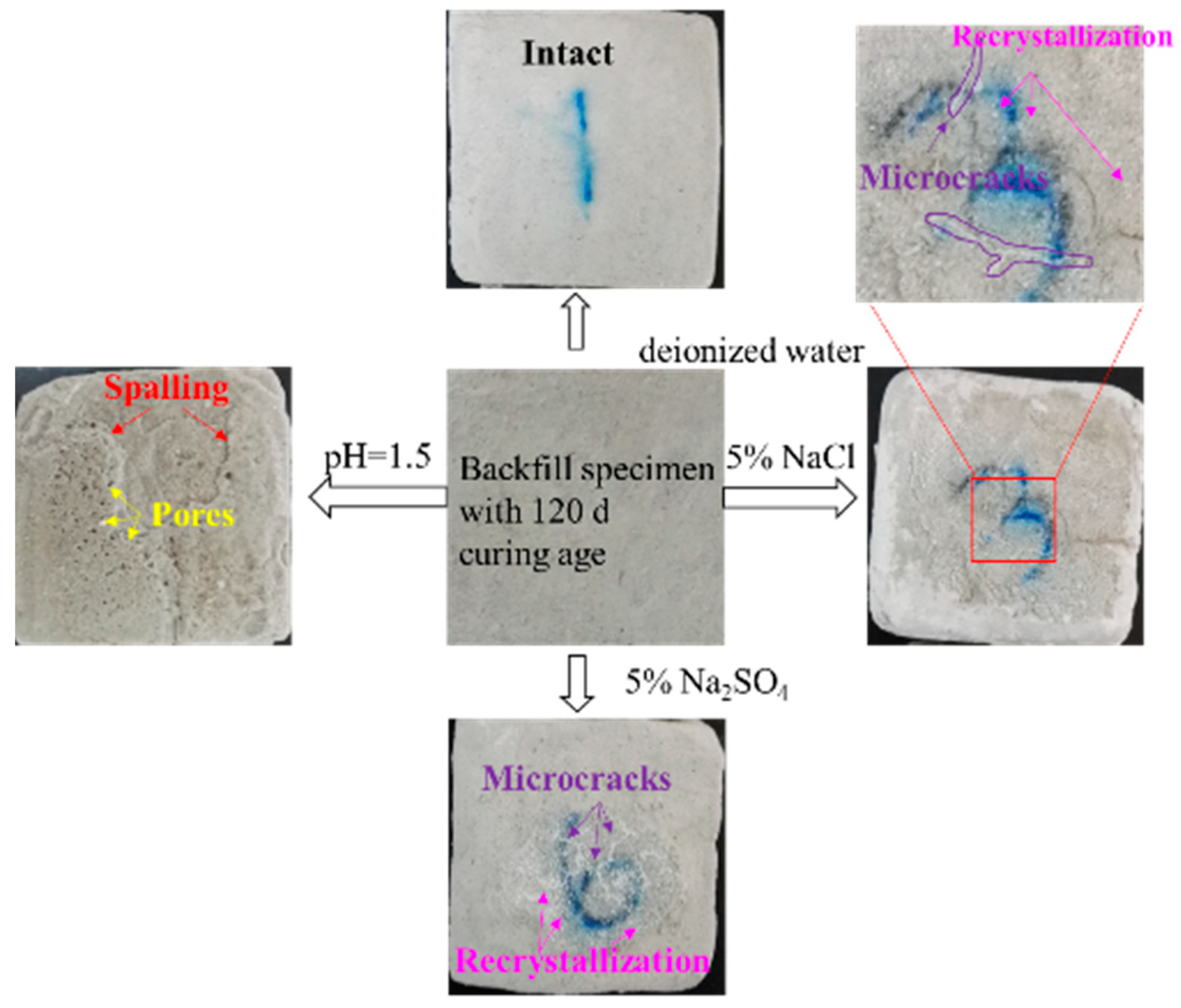
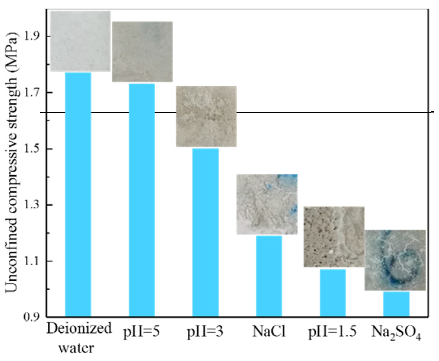
3.1.1. Visual Assessment

Figure 3 shows the appearance of the PG-based backfill specimens after 30 drying-wetting cycles. Specimens exposed to deionized water were visually intact, while deterioration was observed for specimens under other conditions (in both acidic and saline conditions). When the specimens were soaked in acidic solutions, there was obvious spalling and pores on the surface of the specimens. When specimens were exposed to saline solutions, there were quite different destruction modes, with salting-out and microcracks observed. Due to the recrystallization of saline, a great number of white crystals appeared on the surface of the backfill specimens. To some extent, the crystallization pressure contributes to the formation of microcracks [31]. Notably, when the specimens were exposed to 5% Na2SO4, there was an obvious propagation of microcracks, resulting from the expansion of secondary gypsum and secondary ettringite. Presumably, the large amount of SO42– in the solution combines with Ca2+ derived from C–H or C–S–H to form the secondary gypsum [32,33,34,35]. At the same time, SO42– may also promote the continued growth of ettringite [36]. The expansive properties of these secondary products seemingly enhance the formation of microcracks in the backfill.

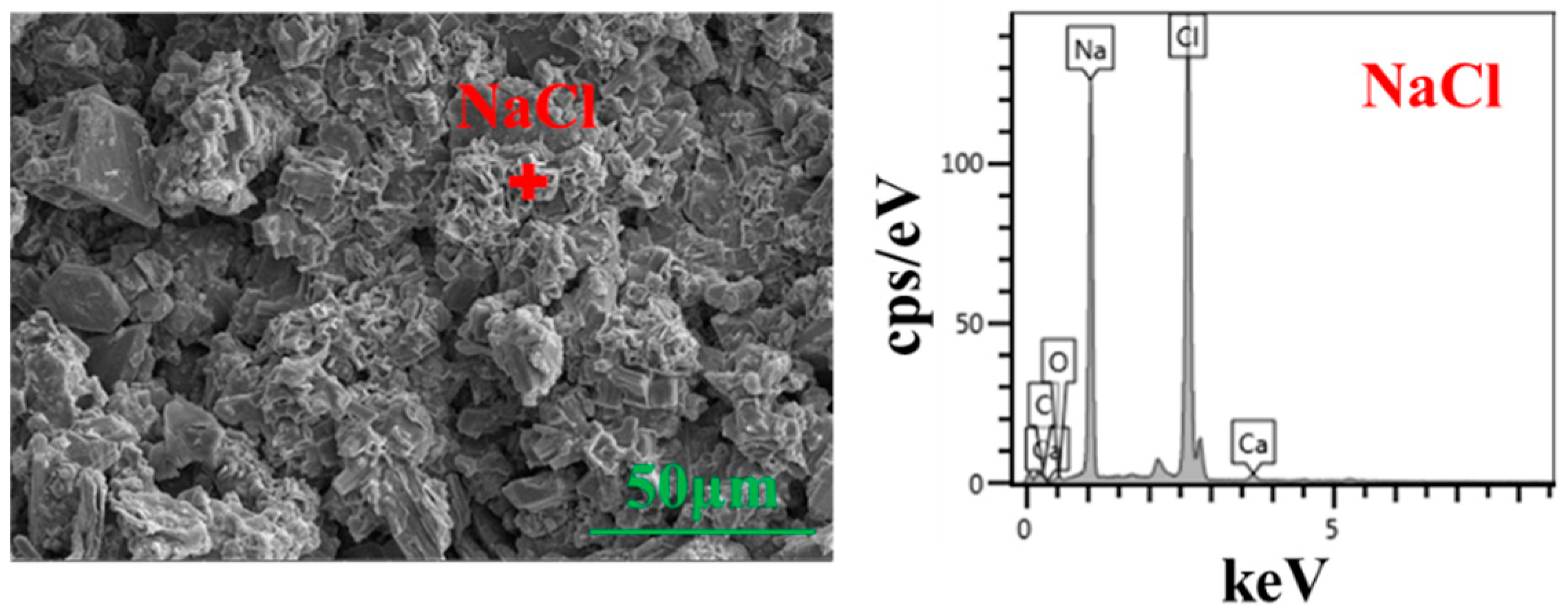
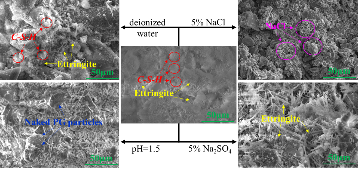
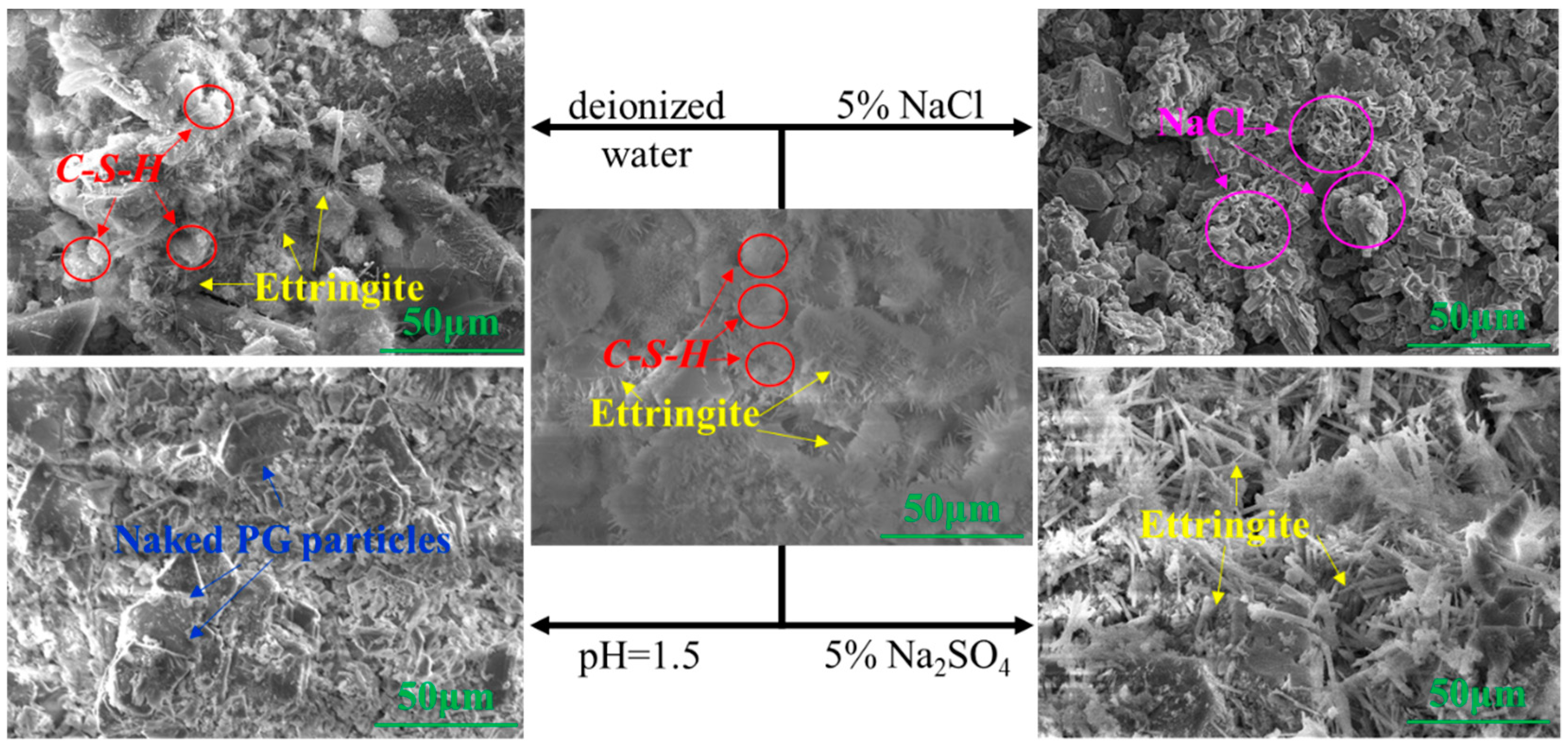
3.1.2. Microstructure

The microstructure of the deteriorated specimens was studied by SEM–EDS, as shown in Figure 4. For the specimens cured for 120 days under normal conditions (at the temperature of 20 °C and humidity of 95%), the hydration process proceeded smoothly, and the PG particles were surrounded by a large amount of hydration products, including ettringite and C–S–H. However, for the specimens subjected to acidic and saline solutions, there were some morphological changes after 30 drying-wetting cycles. In the acidic environment (pH = 1.5), a large number of naked PG particles were observed, which may be related to the dissolution of hydration products [37]. As a result, conjunctions of the PG particles were broken, resulting in spalling of the PG-based backfill from a macroscopic perspective. In the NaCl solution, many regular crystals among the PG particles were observed, with EDS analysis indicating that the regular crystals were recrystallized NaCl (as presented in Figure 5). A large amount of recrystallized salt was observed in the SEM images, which was consistent with the visual observation results. When the specimens were submerged in 5% NaCl solution, salt recrystallization inside the backfill generated disruptive pressure and contributed to the propagation and emergence of microcracks, as shown in Figure 3. For the specimens submerged in Na2SO4 solution, a great amount of needle-like ettringite and recrystallized Na2SO4 was observed between the PG particles. As the volume of secondary ettringite and recrystallized Na2SO4 increased [38], it induced crystallization pressure, culminating in the cracking of the backfill specimens.

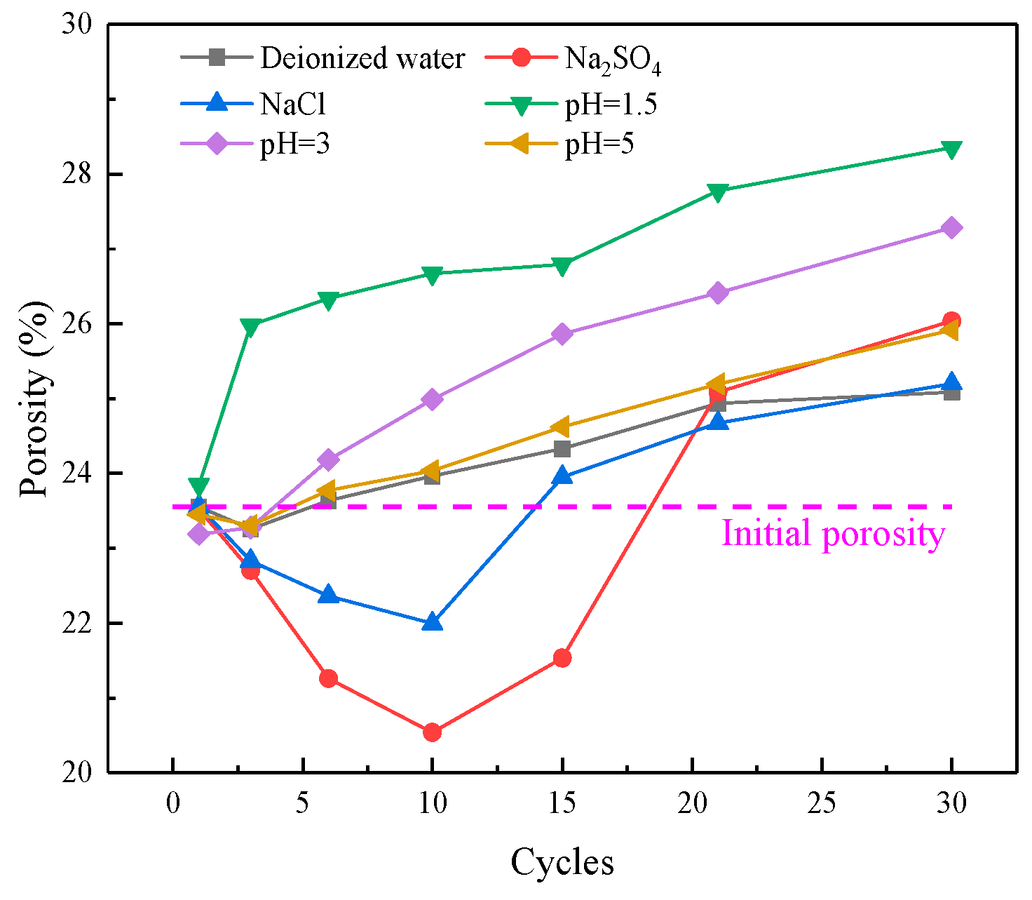
3.1.3. Pore Structure

Pore structure has a significant influence on the mechanical properties of cemented backfill [39,40]. Thus, the porosity of the backfill specimens was measured to evaluate the mechanical performance of the PG-based backfill. In this study, the porosity was characterized by the mass ratio of pore water and the saturated specimen, as shown in Equation (1).
Figure 6 shows the porosity of the backfill specimens after 30 drying-wetting cycles. The porosity of specimens exposed to deionized water after the first drying-wetting cycle (23.55%) could be interpreted as the initial state, as shown by the dotted line in Figure 6. It may be observed that in deionized water, the porosity of the specimens increased slightly with the extension of drying-wetting cycles. A probable reason for this is the original hydration products that filled in the pores were gradually dissolved.
On the other hand, the porosity of the specimens increased significantly in acidic conditions. After 30 total drying-wetting cycles, specimens exposed to acidic conditions showed a gradual increase in porosity with an increase in the acidity of the leachates, which was highly noticeable in comparison to the specimen submerged in deionized water. This increase in porosity in acidic conditions may be explained as follows: Firstly, the presence of more H+ was able cause greater dissolution of the hydration products, resulting in the exposure of naked PG—as presented in Figure 4. Secondly, the solubility of the aggregate (CaSO4·2H2O) increased with the increase in H+, resulting in more voids in the backfill. Hence, there was a higher porosity in the acidic condition.
When the specimens were immersed in saline solutions, the porosity of the specimens first decreased and then increased. In the first ten cycles, the continuous recrystallization of the saline (Na2SO4 and NaCl) filled up tiny pores in specimens, probably generating the observed decrease in porosity. With the formation of secondary gypsum and ettringite, the porosity of specimens decreased more significantly in the Na2SO4 solution [41]. After ten cycles, however, the porosity increased rapidly with the extension of drying-wetting tests, as shown in Figure 6. This increase in porosity (presented in Figure 6) and the appearance of microcracks (presented in Figure 3) were probably caused by expansive cracks of the recrystallized saline and secondary products.

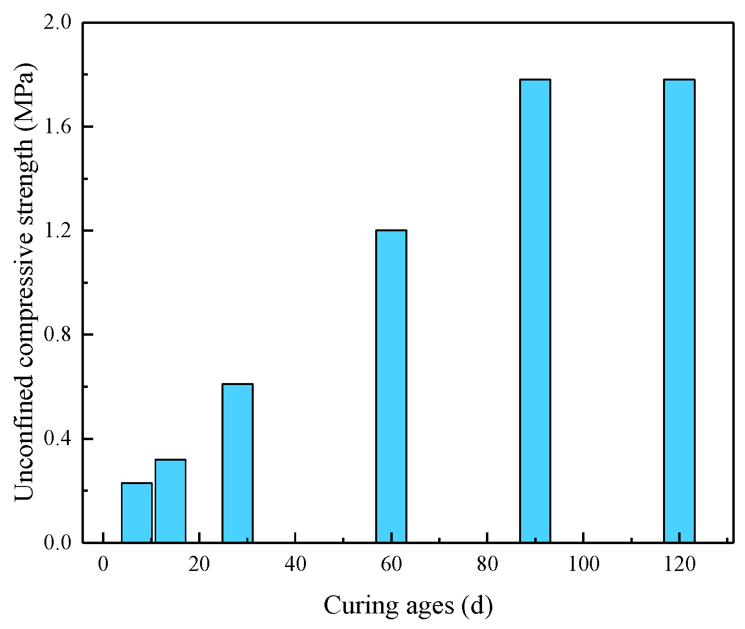
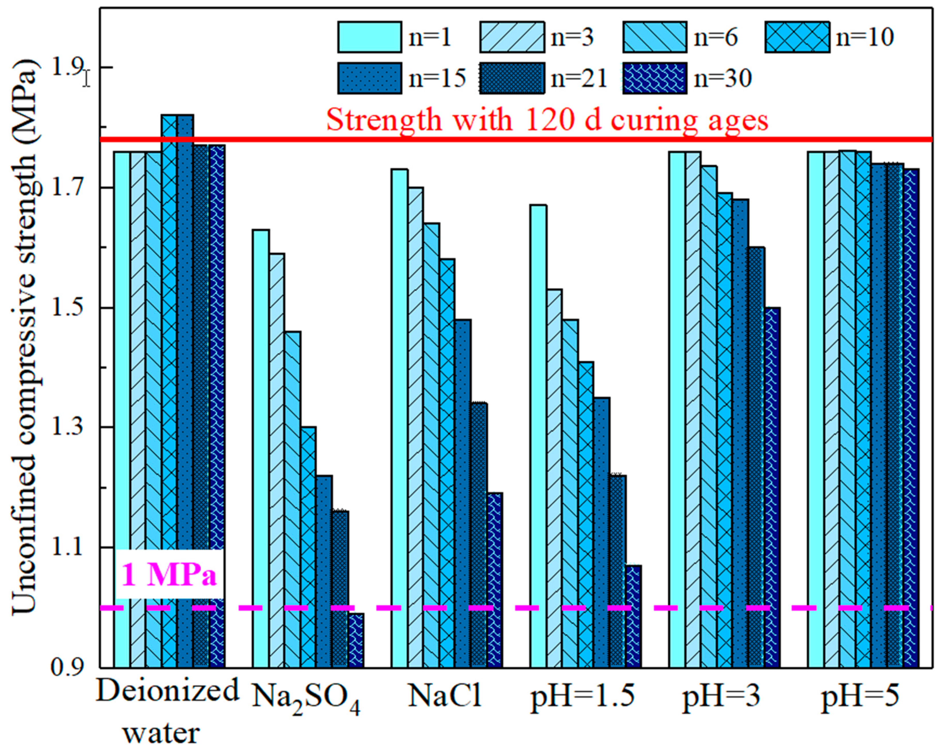
3.1.4. Strength Evolution

To analyze the strength evolution of the backfill, UCS tests were conducted [42,43]. Figure 7 compares the UCS results of the PG-based backfill specimens exposed to different leaching solutions after 1, 3, 6, 10, 15, 21 and 30 drying-wetting cycles. In general, the results of the visual assessment were in good agreement with the UCS tests. As shown in Figure 8, the more severe the visual damage on the surface of the PG-based backfill specimens, the lower the strength of specimens. Specimens in deionized water were visually intact with little change in UCS evolution, whereas both in saline and acid solution, PG-based backfill specimens exhibited visual damage and a decrease in their mechanical strength.
When exposed to the saline solutions, the UCS of the specimens decreased significantly by about 40%. The strength reduction in saline solutions may be explained as follows: Firstly, the large amount of Na+ in the leachates potentially replaces the Ca2+ in C–S–H, which lowered the Ca/Si ratio and resulted in strength reduction of C–S–H [44,45,46]. Secondly, as mentioned above, disruptive pressures generated by recrystallized saline (NaCl and Na2SO4) in pores resulted in the development of microcracks. As a result, the structure was broken with the lowered strength of the specimens [47].
Noticeably, UCS reduction of specimens exposed to Na2SO4 was more pronounced than those exposed to NaCl. This was likely caused by the large formation of expansive ettringite in Na2SO4 solution. As shown in Figure 4, a great deal of ettringite induced by SO42– can enhance the crystallization pressure, leading to the formation of large microcracks. This result suggests that dissolved SO42– is an important factor in accelerating the strength deterioration of backfill. This result was also consistent with a previous study, which reported that a 48% drop in UCS is observed when concrete is exposed to Na2SO4 solution for 22 months [48].
When the specimens were exposed to acidic solutions, the presence of more H+ appeared to lead to a greater loss of UCS. Chen et al. concluded that acid rain attack can decrease the UCS of cementitious materials by 34.2% [21]. In this study, the UCS of the backfill decreased by 39.9%, 15.7%, and 2.81% for the acidic exposure solutions of pH 1.5, 3 and 5, respectively (after 30 drying-wetting cycles). This decrease in strength was probably caused by the dissolution of hydration products, which plays a key role in strength enhancement. Firstly, as shown in Figure 4, naked PG particles indicated the dissolution of hydration products. Secondly, the low pH value of pore water was able to directly inhibit the hydration processes, resulting in decreased strength [49]. In addition to the decrease of hydration products, the dissolution of the aggregate (CaSO4·2H2O) contributed to strength reduction. The solubility of CaSO4·2H2O increased with the decrease in pH values, resulting in structural deterioration and the decrease in the strength of the backfill.
Studies have shown that, in a mine, adequate UCS is about 0.7–2.0 MPa [50,51], and the required strength varies largely in line with the function and application of the backfill. According to mine operators, adequate strength of PG-based backfill is about 1.0 MPa. As shown in Figure 8, the lowest residual strength is 0.99 MPa (Na2SO4, 30 cycles). In this case, the PG-based backfill can satisfy the safety requirements for operation in mines, even when subjected to extremely unfavorable conditions (e.g., high salinity or acidity).

3.2. Impurity Dynamics Through Drying-Wetting Cycles

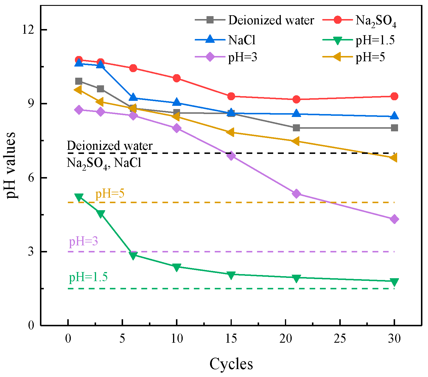
3.2.1. Fluctuation of pH Values

It is well known that pH has an important influence on the hydration process of cemented backfill [49]. Therefore, the pH values of leachates during 30 drying-wetting cycles were measured to assess the hydration process of the PG-based backfill, the results of which are presented in Figure 9. The pH value of each leachate was higher than that of its original solution. When the specimens were immersed in deionized water, alkaline cementitious agents led to the alkalescence of the leachates. In the acidic environment, hydration products, such as C–H and C–S–H, may have reacted with H+, resulting in a pH higher than that of the original solutions [21]. For the specimens exposed to saline solution, the pH value of the leachates was higher than that of the specimens exposed to deionized water, since SO42– and Cl could react as follows [19,52]:
Ca ( OH ) 2 + 2 SO 4 2 + 2 H 2 O = CaSO 4 2 H 2 O + 2 OH - a   =   1 ,
Ca ( OH ) 2 + 2 Cl - = CaCl 2 + 2 OH -
resulting in the release of OH and a rapid increase in pH values. Generally speaking, the pH value of each leachate decreased as the drying-wetting cycles proceeded, presumably due to the consumption of alkaline substances in the backfill specimens [7].

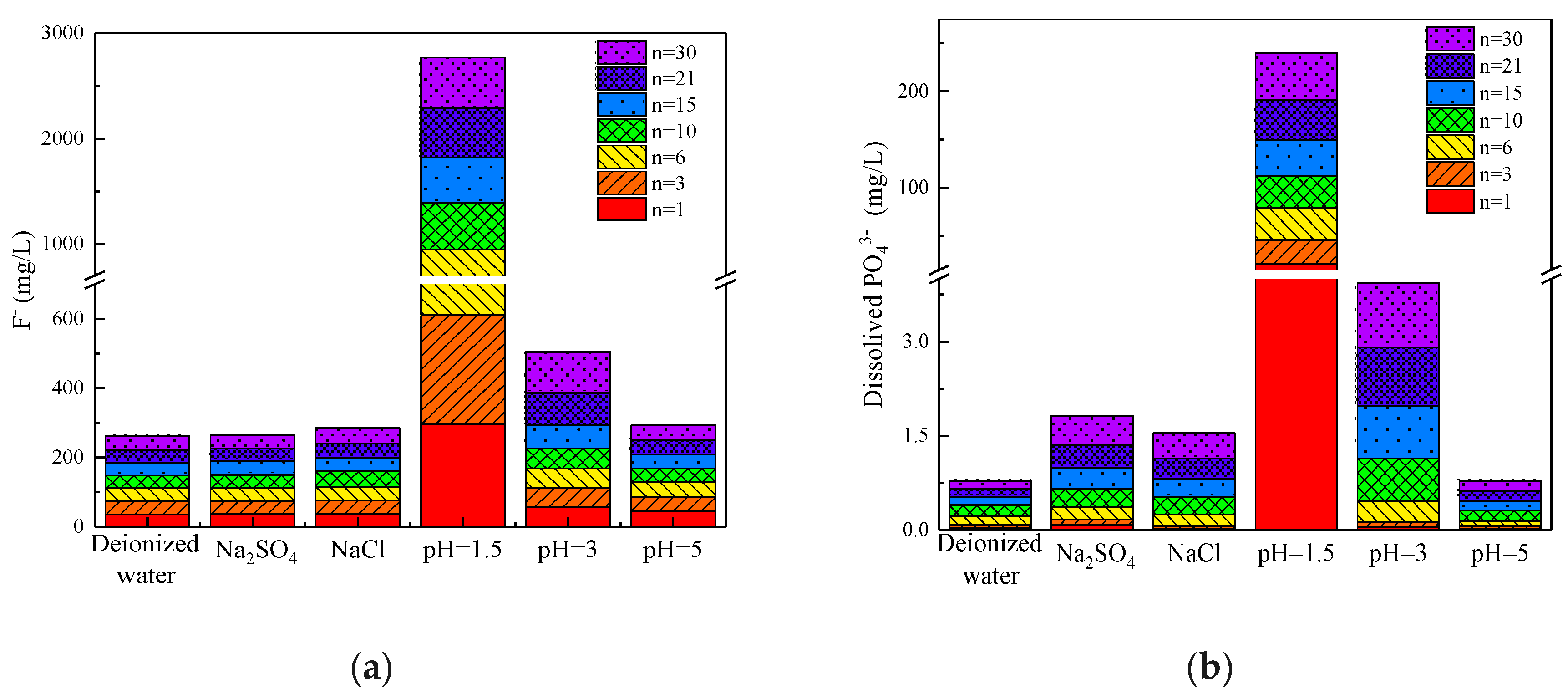
3.2.2. Dynamics of Phosphate and Fluoride

Previous studies have focused on the mechanical performance of mine backfill. However, PG, the aggregate of PG-based backfill, contains some impurities, such as phosphate and fluoride, which may cause serious environmental pollution [53]. Previous studies have shown that impurities originating from PG can be effectively fixed during the backfill process [7,22]. In PG-based backfill slurry, fluoride reacts with calcium to form precipitated Ca–F compounds (such as CaF2) and Ca–P compounds (such as Ca3(PO4)2 and CaHPO4) [8]. However, these solidified impurities may be gradually released over time under unfavorable conditions [54]. Thus, a crucial point of reusing PG as an aggregate is to assess the chemical stability of the impurities in the PG-based backfill, since the backfill would be affected by underground conditions for a long period.
The pollution risk of phosphate and fluoride to water bodies has been emphasized recently. Figure 10 compares the cumulative leaching quantities of fluoride and dissolved phosphate in different the leachates. Generally, these findings suggest that solidified components can be released under unfavorable conditions after drying-wetting cycles, while the release quantities of phosphate and fluoride is related to the solution type.
As shown in Figure 10, a low pH has the largest impact on the release of fluoride and phosphate. The cumulative quantity of fluoride is increased by over 10 times when specimens are exposed to an acidic environment. Undissolved CaF2 is dissolved slightly by H+, leading to the release of fluoride. According to Figure 10b, in terms of phosphate, the cumulative quantity of dissolved phosphate leached by an acidic solution (pH = 1.5) is almost 150 times higher than that leached by deionized water. The sharp increase observed in the content of dissolved phosphate may be explained by the following reasons: Firstly, the dissolution of precipitated Ca–P compounds is an important factor. Secondly, the lattice constant of eutectic phosphate (CaHPO4·2H2O) is similar to that of CaSO4·2H2O, indicating that CaHPO4·2H2O enters the CaSO4·2H2O lattice to form a eutectic phosphate. As the CaSO4·2H2O lattice is seemingly destroyed by H+, eutectic phosphate is released into the surrounding environment, leading to an increase in the content of dissolved phosphate.
Saline solution had little influence on the release of fluoride, as shown in Figure 10a. The cumulative fluoride quantities in both Na2SO4 and NaCl solutions were similar to those in deionized water. However, the release of phosphate in saline solutions was slightly higher than that of deionized water (almost 1.8 mg/L in saline solutions and 0.8 mg/L in deionized water) due to the damage of CaSO4·2H2O crystals. In addition, a portion of phosphate in the form of eutectic phosphate appeared to dissolve out of the gypsum lattice dissolution.

4. Conclusions

Through a drying-wetting test of 30 cycles, this study examined the mechanical change of PG-based backfill and the environmental dynamics of the pollutants. Based on the test results, a number of conclusions were drawn.
Firstly, in terms of the environment, high acidity had the largest impact on the release of impurities, since solidified components were dissolved by H+. In comparison, the presence of environmental saline solution had a slight effect on the release of impurities. Secondly, from the perspective of strength evolution, both salinity and acidity led to significant strength reduction in the backfill under different mechanisms. In the acidic environment, the dissolution of hydration products was the main reason for the reduction in strength. In the saline solution, the strength of the backfill specimens was lowered due to the expansion of micro-cracks and the weakening of hydration products. Although significant strength reduction was observed under unfavorable conditions, PG-based backfill can maintain adequate strength for the safe operation of mines. Therefore, the utilization of PG-based backfill technology is an effective method to fill the cavity of mines.

Author Contributions

X.L. and Y.S. conceived and designed the theoretical framework; S.Z. performed the experiments and wrote the manuscript; Y.Z.; C.M.; Z.C.; J.D.; and L.L. corrected the tables and figures. All authors participated in the finalization of the written manuscript. X.L. and Y.S. acted as the supervisors of the project and acquired all the necessary funding.

Funding

This work was supported by the Project of Key Research Development Program of Hunan (Grant No. 2017SK2251), Hunan Natural Science Foundation (Grant No. 2018JJ3664) and the Fundamental Research Funds for the Central Universities of Central South University, China (Grant No. 2018zzts724 and 2019zzts305).

Acknowledgments

We thank Modern Analysis and Testing Center of CSU for assistance with SEM analysis.

Conflicts of Interest

The authors declare no conflict of interest.

References

  1. Wu, D.; Hou, Y.B.; Deng, T.F.; Chen, Y.Z.; Zhao, X.L. Thermal, hydraulic and mechanical performances of cemented coal gangue-fly ash backfill. Int. J. Miner. Process. 2017, 162, 12–18. [Google Scholar] [CrossRef]
  2. Jiang, H.Q.; Fall, M.; Liang, C. Yield stress of cemented paste backfill in sub-zero environments: experimental results. Miner. Eng. 2016, 92, 141–150. [Google Scholar]
  3. Kesimal, A.; Yilmaz, E.; Ercikdi, B.; Alp, I.; Deveci, H. Effect of properties of tailings and binder on the short-and long-term strength and stability of cemented paste backfill. Mater. Lett. 2005, 59, 3703–3709. [Google Scholar] [CrossRef]
  4. Wang, S.F.; Li, X.B.; Wang, S.Y. Three-dimensional mineral grade distribution modelling and longwall mining of an underground bauxite seam. Int. J. Rock. Mech. Min. 2018, 103, 123–136. [Google Scholar] [CrossRef]
  5. Guo, G.L.; Zhu, X.J.; Zha, J.F.; Wang, Q. Subsidence prediction method based on equivalent mining height theory for solid backfilling mining. T. Nonferr. Metal. Soc. 2014, 24, 3302–3308. [Google Scholar] [CrossRef]
  6. Ma, D.; Duan, H.Y.; Liu, J.F.; Li, X.B.; Zhou, Z.L. The role of gangue on the mitigation of mining-induced hazards and environmental pollution: An experimental investigation. Sci. Total Environ. 2019, 664, 436–448. [Google Scholar] [CrossRef] [PubMed]
  7. Li, X.B.; Du, J.; Gao, L.; He, S.Y.; Gan, L.; Sun, C.; Shi, Y. Immobilization of phosphogypsum for cemented paste backfill and its environmental effect. J. Clean. Prod. 2017, 156, 137–146. [Google Scholar] [CrossRef]
  8. Chen, Q.S.; Zhang, Q.L.; Qi, C.C.; Fourie, A.; Xiao, C.C. Recycling phosphogypsum and construction demolition waste for cemented paste backfill and its environmental impact. J. Clean. Prod. 2018, 186, 418–429. [Google Scholar] [CrossRef]
  9. Ercikdi, B.; Cihangir, F.; Kesimal, A.; Deveci, H.; İbrahim, A. Utilization of water-reducing admixtures in cemented paste backfill of sulphide-rich mill tailings. J. Hazard Mater. 2010, 179, 940–946. [Google Scholar] [CrossRef]
  10. Jiang, H.Q.; Fall, M. Yield stress and strength of saline cemented tailings in sub-zero environments: portland cement paste backfill. Int. J. Miner. Process. 2017, 160, 68–75. [Google Scholar] [CrossRef]
  11. Helson, O.; Eslami, J.; Beaucour, A.L.; Noumowe, A.; Gotteland, P. Durability of soil mix material subjected to wetting/drying cycles and external sulfate attacks. Constr. Build. Mater. 2018, 192, 416–428. [Google Scholar] [CrossRef]
  12. Wojciech, P. Analysis of carbonate and sulphate attack on concrete structures. Eng. Fail. Anal. 2017, 79, 606–614. [Google Scholar]
  13. Kunther, W.; Lothenbach, B.; Scrivener, K.L. On the relevance of volume increase for the length changes of mortar bars in sulfate solutions. Cement Concrete Res. 2013, 46, 23–29. [Google Scholar] [CrossRef]
  14. Fall, M.; Pokharel, M. Coupled effects of sulphate and temperature on the strength development of cemented tailings backfills: Portland cement-paste backfill. Cement Concrete Res. 2010, 32, 819–828. [Google Scholar] [CrossRef]
  15. Cihangir, F.; Ercikdi, B.; Kesimal, A.; Ocak, S.; Akyol, Y. Effect of sodium-silicate activated slag at different silicate modulus on the strength and microstructural properties of full and coarse sulphidic tailings paste backfill. Constr. Build. Mater. 2018, 185, 555–566. [Google Scholar] [CrossRef]
  16. Zhang, J.R.; Sun, M.; Hou, D.S.; Li, Z.J. External sulfate attack to reinforced concrete under drying-wetting cycles and loading condition: Numerical simulation and experimental validation by ultrasonic array method. Constr. Build. Mater. 2017, 139, 365–373. [Google Scholar] [CrossRef]
  17. Cihangir, F.; Akyol, Y. Mechanical, hydrological and microstructural assessment of the durability of cemented paste backfill containing alkali-activated slag. Int. J. Min. Reclam. Env. 2016, 185, 1–21. [Google Scholar] [CrossRef]
  18. Wang, Q.; Yan, P.Y.; Yang, J.W.; Zhang, B. Influence of steel slag on mechanical properties and durability of concrete. Constr. Build. Mater. 2013, 47, 1414–1420. [Google Scholar] [CrossRef]
  19. Liu, J.J.; Zha, F.S.; Xu, L.; Yang, C.B.; Chu, C.F.; Tan, X.H. Effect of chloride attack on strength and leaching properties of solidified/stabilized heavy metal contaminated soils. Eng. Geol. 2018, 246, 28–35. [Google Scholar] [CrossRef]
  20. Ragoug, R.; Metalssi, O.O.; Barberon, F.; Torrenti, J.M.; Roussel, N.; Divet, L.; Jean-Baptiste, E.L. Durability of cement pastes exposed to external sulfate attack and leaching: Physical and chemical aspects. Cement Concrete Res. 2019, 116, 134–145. [Google Scholar] [CrossRef]
  21. Chen, M.C.; Wang, K.; Xie, L. Deterioration mechanism of cementitious materials under acid rain attack. Title of the article. Eng. Fail. Anal. 2013, 27, 272–285. [Google Scholar] [CrossRef]
  22. Shi, Y.; Gan, L.; Li, X.B.; He, S.Y.; Sun, C.; Gao, L. Dynamics of metals in backfill of a phosphate mine of guiyang, China using a three-step sequential extraction technique. Chemosphere 2018, 192, 354–361. [Google Scholar] [CrossRef]
  23. Chen, Q.Y.; Tyrer, M.; Hills, C.D.; Yang, X.M.; Carey, P. Immobilisation of heavy metal in cement-based solidification/stabilisation: a review. Waste Manag. 2009, 29, 390–403. [Google Scholar] [CrossRef] [PubMed]
  24. Du, Y.J.; Wei, M.L.; Reddy, K.R.; Wu, H.L. Effect of carbonation on leachability, strength and microstructural characteristics of KMP binder stabilized Zn and Pb contaminated soils. Chemosphere 2015, 144, 1033–1042. [Google Scholar] [CrossRef] [PubMed]
  25. Du, Y.J.; Wei, M.L.; Reddy, K.R.; Liu, Z.P.; Jin, F. Effect of acid rain ph on leaching behavior of cement stabilized lead-contaminated soil. J. Hazard. Mater. 2014, 271, 131–140. [Google Scholar] [CrossRef]
  26. Qu, Q.L.; Deng, Z.L.; Yang, Y.B.; Li, Z.G.; Yang, B.L. A Manufacturing Method for Producing Composite Phosphorus Slag Powder. China Patent ZL2012102079216, 21 June 2012. (In Chinese). [Google Scholar]
  27. Li, J.S.; Xue, Q.; Wang, P.; Li, Z.Z.; Liu, L. Effect of drying-wetting cycles on leaching behavior of cement solidified lead-contaminated soil. Chemosphere 2014, 117, 10–13. [Google Scholar] [CrossRef]
  28. Li, K.G.; Zheng, D.P.; Huang, W.H. Mechanical behavior of sandstone and its neural network simulation of constitutive model considering cyclic drying-wetting effect. Rock. Soil. Mech. 2013, 34, 168–173. [Google Scholar]
  29. Abdelhadi, K.; Latifa, O.; Khadija, B.; Lahcen, B. Valorization of mining waste and tailings through paste backfilling solution, Imiter operation, Morocco. Int. J. Min. Sci. Tech. 2016, 26, 511–516. [Google Scholar]
  30. Zhou, K.P.; Liu, T.Y.; Hu, Z.X. Exploration of damage evolution in marble due to lateral unloading using nuclear magnetic resonance. Eng. Geol. 2018, 244, 75–85. [Google Scholar] [CrossRef]
  31. Nehdi, M.L.; Suleiman, A.R.; Soliman, A.M. Investigation of concrete exposed to dual sulfate attack. Cement Concrete Res. 2014, 64, 42–53. [Google Scholar] [CrossRef]
  32. Collepardi, M. A state-of-the-art review on delayed ettringite attack on concrete. Cement Concrete Res. 2003, 25, 401–407. [Google Scholar] [CrossRef]
  33. Tixier, R.; Mobasher, B. Modeling of damage in cement-based materials subjected to external sulfate attack. I: Formulation. J. Mater. Civil Eng. 2003, 15, 305–313. [Google Scholar] [CrossRef]
  34. Andrés, E.I.; Carlos, M.L.; Ignacio, C. Chemo-mechanical analysis of concrete cracking and degradation due to external sulfate attack: A meso-scale model. Cement Concrete Comp. 2011, 33, 411–423. [Google Scholar]
  35. Benzaazoua, M.; Belem, T.; Bussière, B. Chemical factors that influence the performance of mine sulphidic paste backfill. Cement Concrete Res. 2002, 32, 1133–1144. [Google Scholar] [CrossRef]
  36. Cefis, N.; Comi, C. Chemo-mechanical modelling of the external sulfate attack in concrete. Cement Concrete Res. 2017, 93, 57–70. [Google Scholar] [CrossRef]
  37. Hadigheh, S.A.; Gravina, R.J.; Smith, S.T. Effect of acid attack on FRP-to-concrete bonded interfaces. Constr. Build. Mater. 2017, 152, 285–303. [Google Scholar] [CrossRef]
  38. Andre, B.; Moien, R.; Tilo, P.; Cyrill, G.; Florian, S.; Marlene, S.; Claudia, B.; Isabel, G.; Florian, E.; Florian, M. Effect of very high limestone content and quality on the sulfate resistance of blended cements. Constr. Build. Mater. 2018, 188, 1065–1076. [Google Scholar]
  39. Wang, Y.; Yuan, Q.; Deng, D.; Ye, T.; Fang, L. Measuring the pore structure of cement asphalt mortar by nuclear magnetic resonance. Constr. Build. Mater. 2017, 137, 450–458. [Google Scholar] [CrossRef]
  40. Zhang, J.; Deng, H.W.; Taheri, A.; Deng, J.R.; Ke, B. Effects of Superplasticizer on the Hydration, Consistency, and Strength Development of Cemented Paste Backfill. Minerals 2018, 8, 381. [Google Scholar] [CrossRef]
  41. Min, C.D.; Li, X.B.; He, S.Y.; Zhou, S.T.; Zhou, Y.N.; Yang, S.; Shi, Y. Effect of mixing time on the properties of phosphogypsum-based cemented backfill. Constr. Build. Mater. 2019, 210, 564–573. [Google Scholar] [CrossRef]
  42. Fall, M.; Benzaazoua, M. Modeling the effect of sulphate on strength development of paste backfill and binder mixture optimization. Cement Concrete Res. 2005, 35, 301–314. [Google Scholar] [CrossRef]
  43. Wu, J.Y.; Feng, M.M.; Chen, Z.Q.; Mao, X.B.; Han, G.S.; Wang, Y.M. Particle Size Distribution Effects on the Strength Characteristic of Cemented Paste Backfill. Minerals 2018, 8, 322. [Google Scholar] [CrossRef]
  44. Daisuke, S. Chemical alteration of calcium silicate hydrate (C–S–H) in sodium chloride solution. Cement Concrete Res. 2008, 38, 1270–1275. [Google Scholar]
  45. Zhou, X.S.; Lin, X.; Huo, M.J.; Zhang, Y. The hydration of saline oil-well cement. Cement Concrete Res. 1996, 26, 1753–1759. [Google Scholar] [CrossRef]
  46. Komljenović, M.M.; Baščarević, Z.; Marjanović, N.; Nikolić, V. Decalcification resistance of alkali-activated slag. J. Hazard Mater. 2012, 233–234, 112–121. [Google Scholar] [CrossRef]
  47. Najjar, M.F.; Nehdi, M.L.; Soliman, A.M.; Azabi, T.M. Damage mechanisms of two-stage concrete exposed to chemical and physical sulfate attack. Constr. Build. Mater. 2017, 137, 141–152. [Google Scholar] [CrossRef]
  48. Tang, Z.; Li, W.G.; Ke, G.J.; Zhou, J.L.; Tam, V.W.Y. Sulfate attack resistance of sustainable concrete incorporating various industrial solid wastes. J. Clean. Prod. 2019, 218, 810–822. [Google Scholar] [CrossRef]
  49. Fan, Y.F.; Hu, Z.Q.; Zhang, Y.Z.; Liu, J.L. Deterioration of compressive property of concrete under simulated acid rain environment. Constr. Build. Mater. 2010, 24, 1975–1983. [Google Scholar] [CrossRef]
  50. Brackebusch, F.W. Basics of paste backfill systems. Miner. Eng. 1994, 46, 1175–1178. [Google Scholar]
  51. Zhao, Y.; Soltani, A.; Taheri, A.; Karakus, M.; Deng, A. Application of Slag–Cement and Fly Ash for Strength Development in Cemented Paste Backfills. Minerals 2019, 9, 22. [Google Scholar] [CrossRef]
  52. Geng, J.; Easterbrook, D.; Li, L.Y.; Mo, L.W. The stability of bound chlorides in cement paste with sulfate attack. Cement Concrete Res. 2015, 68, 211–222. [Google Scholar] [CrossRef]
  53. Al-Masri, M.S.; Amin, Y.; Ibrahim, S.; Al-Bich, F. Distribution of some trace metals in Syrian phosphogypsum. Appl. Geochem. 2004, 19, 747–753. [Google Scholar] [CrossRef]
  54. Li, X.B.; Zhou, Y.N.; Zhu, Q.Q.; Zhou, S.T.; Min, C.D.; Shi, Y. Slurry Preparation Effects on the Cemented Phosphogypsum Backfill through an Orthogonal Experiment. Minerals 2019, 9, 31. [Google Scholar] [CrossRef]
Figure 1. Particle size distributions of the phosphogypsum and binder.
Minerals 09 00321 g001
Figure 2. The development of unconfined compressive strength of the phosphogypsum (PG)-based backfill specimens within 120 days.
Minerals 09 00321 g002
Figure 3. Visual inspection of the PG-based backfill specimens with different exposure solutions after 30 drying-wetting cycles.
Minerals 09 00321 g003
Figure 4. Scanning electron microscope (SEM) images of the PG-based backfill specimens with 120 d curing age and different exposure solutions after 30 drying-wetting cycles. Magnification factor: 2500×; accelerating voltage: 10.00 kV; and working distance: 6.0 mm.
Minerals 09 00321 g004
Figure 5. Energy dispersive spectrometry (EDS) analysis of specimens exposed to NaCl. Magnification factor: 2500×; accelerating voltage: 10.00 kV; and working distance: 6.0 mm.
Minerals 09 00321 g005
Figure 6. Variation of the porosity of hardened backfill samples with different drying-wetting cycles.
Minerals 09 00321 g006
Figure 7. Unconfined compressive strength of the PG-based backfill specimens at different drying-wetting cycles and exposure solutions.
Minerals 09 00321 g007
Figure 8. Visual inspection of the PG-based backfill specimens with different exposure solutions after 30 drying-wetting cycles.
Minerals 09 00321 g008
Figure 9. pH values in 30 drying-wetting cycles; the dotted lines indicate the initial values for each solution.
Minerals 09 00321 g009
Figure 10. The cumulative leaching quantities of hazardous impurities in leachates: (a) The cumulative leaching quantities of fluoride and (b) the cumulative leaching quantities of dissolved phosphate.
Minerals 09 00321 g010
Table 1. Chemical compositions and physical characteristics of the phosphogypsum and binder.
Chemical CompositionPGBinder
%%
SiO21.723.4
Fe2O30.32.6
CaO35.954.4
MgO0.11.7
SO350.85.5
P2O52.61.7
Na2O0.11.3
K2O0.10.9
TiO20.10.5
Physical Characteristic
D10 (µm)17.516.31
D30 (µm)42.7913.56
D60 (µm)92.0529.18
Cu = D60/D105.26
Cc = D302/(D60 × D10)1.14
Specific gravity2.353.21

