Abstract
To reveal the growth behavior and size characterization of iron particles in coal-based reduction, we reduced oolitic hematite–coal composite briquettes at various temperatures, durations and ore size fractions. The degree of metallization and microstructure of the reduced briquettes and the characteristic of iron particle size were investigated through chemical composition analysis, scanning electron microscopy, energy dispersive spectroscopy, and Bgrimm process mineralogy analysis. Results showed that iron oxides in the oolitic hematite ore were reduced to metallic iron from outer to inner layers; these oxides gradually grew into quasi-spherical iron particles with random distribution in the gangue. As reduction continued, iron grains agglomerated occurred, and iron particle clusters were formed in the form of quasi-spherical, chained, blocky, and clavate when they were viewed in the cross section. The boundaries among the iron grains of the iron particle cluster continuously faded and disappeared, and an iron particle with increased size and homogeneity was finally produced. The reduction temperature, time, and ore size fraction influenced the reduction of composite briquettes and iron particle size. The degree of metallization increased as reduction temperature was increased, reduction time was extended, or ore size fraction was decreased until the equilibrium of reaction was achieved. Moreover, the iron particle size gradually increased as reduction temperature was increased, reduction time was extended, or ore size fraction was decreased.
1. Introduction
Oolitic hematite ore is a significant existing form of iron ores, which are widely distributed in France, Germany, the United States, Canada, Pakistan, China, and other countries [1,2]. In China, 3.72 billion tons of explored reserves of oolitic hematite ores accounts for approximately 1/9 of total iron ore resources [3]. As one of the most refractory iron ores in the world, oolitic hematite ore possesses complex composition, microstructure, and embedded relationship [4,5], contains some metallic minerals, such as hematite (Fe2O3), siderite (FeCO3), and limonite (Fe2O3·nH2O), and comprises some non-metallic minerals, such as quartz (SiO2), chamosite [(Fe,Mg)3(Fe,Fe)3[AlSi3O10](OH)3], and collophanite (Ca3P2O8·H2O). These ultra-fine-grained minerals cement together to form a disseminated oolitic structure.
Flaky hematite and other minerals in oolitic ores form a layered structure with quartz or chlorite at the center and constitute a layer-by-layer concentric ring structure. Iron minerals from raw ores cannot be separated through conventional mineral processing methods because of the complex compositions and embedded relationship of oolitic hematite ores [6,7,8]. A new process named coal-based reduction followed by magnetic separation has been used to produce metallic iron powder from oolitic iron ores [9,10,11,12,13]. In this process, iron oxides are reduced to metallic iron by coal, and then the reduced samples are ground to obtain a liberation size and separated through magnetic separation. The iron grade and recovery of metallic iron powder obtained through this process generally reach more than 90 wt %, thereby providing a good substitute steel scrap in electric arc furnaces for steelmaking [14,15].
Studies on the coal-based reduction of oolitic hematite ores have revealed that iron oxides in oolitic ores are reduced to metallic iron via the route of Fe2O3–Fe3O4–FeO–Fe during reduction [16,17,18]. Metallic iron aggregates and separate out to form iron particles and becomes randomly embedded in a slag phase. The size and morphological characteristics of iron particles in reduced samples directly affect grinding efficiency and subsequent magnetic separation because metallic iron with a large particle size can be easily liberated and separated from a slag [19,20]. Although numerous studies have been conducted on process parameters and iron particles in coal-based reduction, the growth behavior and size characterization of iron particles of reduced briquettes during coal-based reduction remain unclear. Therefore, the growth behavior of iron particles and the characteristics of particle size in reduction should be explored to provide a theoretical basis for the selection of technological parameters and optimization of reduction conditions.
In this study, iron ore samples and coal were proportionally mixed and squeezed to a composite briquette. The composite briquettes were then reduced through coal-based reduction at various reduction temperatures, durations, and ore size fractions. The degree of metallization and microstructure of the reduced briquettes were investigated through chemical composition analysis, scanning electron microscopy (SEM), and energy-dispersive X-ray spectroscopy (EDS). The mean size and cumulative frequency distribution of iron particles were obtained using a Bgrimm process mineralogy analyzer (BPMA). Phosphorus removal was disregarded in this study to focus on metallic iron particles.
2. Experimental
2.1. Materials
The raw materials used in this study included oolitic hematite ore, anthracite, and starch gel.
A typical Ningxiang-type oolitic hematite collected from the Guandian Iron Mine, Hubei Province, China, was utilized as a representative sample. Its chemical analysis (Table 1) indicated that the approximate contents of total iron, SiO2, Al2O3, and CaO were 42.21 wt %, 21.80 wt %, 5.47 wt %, and 4.33 wt %, respectively, whereas the contents of the harmful phosphorus and sulfur were 1.31 wt % and 0.13 wt %, respectively. Its X-ray diffraction (XRD) pattern is shown in Figure 1, which illustrated that its major mineral phases were hematite, quartz, chamosite, and apatite (fluorapatite and hydroxyapatite). The oolitic hematite ore was ground 100% to diameters less than 0.1, 1.0, 2.0, and 4.0 mm. The particle size distributions of the crushed samples are shown in Table 2.

Table 1.
Chemical composition analysis of oolitic hematite ore (wt %).
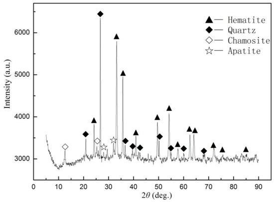
Figure 1.
XRD pattern of oolitic hematite sample.
Table 2.
Particle size distributions of the crushed ores.
Anthracite coal was used as a reductant. The results of its proximate analysis are provided in Table 2, which shows that the coal is high in fixed carbon and comparatively low in harmful elements of S and P. It is a suitable reductant for coal-based direct reduction. Anthracite was crushed to 100% passing 2 mm. The fixed carbon in coal and the CO liberated by gasification are only considered in reduction reactions. The methane, hydrogen and other hydrocarbons in the volatile component are ignored. The coal dosage is determined by C/O molar ratio (i.e., molar ratio of fixed carbon in the coal to reducible oxygen in iron oxides) based on the chemical composition analysis of oolitic iron ore and proximate analysis of coal, as shown in Table 1 and Table 3.
Table 3.
Proximate analysis of of coal (wt %).
Starch gel, a uniformly dispersed system produced by starch and boiling water, was evaluated as an organic binder. First, 5.0 g of industrial starch was accurately weighed and dissolved in 20 mL of water by using a beaker with scale line. Second, boiling water was added and mixed up to 100 mL. The mixture was boiled for 3 min and cooled to room temperature. A starch gel of 5 wt % was obtained.
2.2. Composite Briquette Formation and Reduction
The iron ore samples and coal (the reductant) were thoroughly mixed with a certain amount of starch gel by rigorous stirring. To provide a sufficient reduction atmosphere, the amount of coal addition in the mixture was excessively determined according to a C/O molar ratio of 2.0 based on the calculation of coal dosage. Each mixed sample comprised 60 g of iron ore sample, 23.35 g of coal, and 6.7 mL of starch gel. The mixture was placed in a cast-iron mold, and columnar briquette (diameter = 40 mm; height = 30 mm) was generated by squeezing the mixture at 10 MPa by using a press machine. The prepared briquettes were then dried in an electric oven at 353 K for 24 h. The dried briquettes were stored in a desiccator until operation.
Reduction was carried out in a high-temperature-resistant furnace with a KSL-1400X temperature control programmer (Kejing Company, Hefei, China). A briquette was placed into a 100 mL ceramic crucible, which was quickly placed in the furnace when the temperature of the furnace reached the presupposed temperature. The door of the furnace was subsequently closed as quickly as possible. The temperature was kept at a predetermined time ranging from 20 min to 50 min. Purge gases were not utilized, and the experiments were run under atmospheric conditions. After reduction was completed, the reduced briquettes were cooled down to room temperature by water quenching, crushed to 100% passing 2 mm, and dried at 373 K in a vacuum oven for 4 h. Finally, the reduced samples were obtained. To investigate the growth behavior and particle size of iron particles in the reduction of oolitic hematite–coal composite briquette, we operated under the following conditions: reduction temperatures of 1423, 1473, 1523, and 1548 K; reduction times of 20, 30, 40, and 50 min; and ore size fractions of −0.1, −1.0, −2.0, and −4.0 mm. The degree of metallization, microstructure, and iron particle size of the reduced samples were systematically analyzed and observed.
2.3. Analysis and Characterization
The degree of metallization of the reduced sample was calculated using Equation (1) based on the metallic iron content and the total iron content, which determined by titrimetric method (iron chloride method) in the Analysis Laboratory of Northeastern University (China). The iron chloride method is frequently used to test iron content, including dissolution, reduction and titration, and the titrating solution is potassium bichromate. The morphological characteristics and microstructure of these products were observed using a scanning electron microscope (EVO 18 Research, ZEISS, Oberkochen, Germany). The compositions of metal and slag phases were analyzed with an energy dispersive spectrometer (Quantax 800, BRUKER, Karlsruhe, Germany). The SEM images containing more than 1000 metallic iron particles for each specimen were collected from the reduced briquettes, and a BPMA was used to investigate the particle size.
Bgrimm process mineralogy analysis is conducted in Beijing General Research Institute of Mining & Metallurgy (BGRIMM). The BPMA is composed of a scanning electron microscope, one or two advanced energy dispersive spectrometer and a set of software developed by BGRIMM. The BPMA can distinguish different phases based on a backscattered electron image. Many SEM images of reduced samples systematically photographed were analyzed by the software. The perimeter, cross-sectional area and diameter of each particle were measured. Size characterization of iron particles were calculated and statistic according to the measured data.
The degree of metallization was used to describe the reduction of the composite briquette, which can be calculated according to Equation (1):
where η is the degree of metallization (wt %), MFe is the metallic iron content of reduced briquettes (%), and TFe is the total iron content after reduction (wt %).
Metallic iron formed quasi-spherical particles during reduction. As metallic iron diffused, many iron particles sintered together into an accumulated iron particle cluster. As reduction continued, an iron particle with increased size and homogeneity was obtained.
For a quantitative description of iron particle size, the cross-sectional areas of more than 1000 metallic particles of each briquette were determined with BPMA, and the equivalent diameter of each iron particle can be calculated using Equation (2):
where Di is the equivalent diameter of each measured metallic particle (μm), and Si is the cross-sectional area of the corresponding metallic particle (μm2).
To reveal the effects of reduction temperature, reduction time and ore size fraction on the growth behavior of iron particles, their mean size was calculated by Equation (3). Equation (3) is based on the weighted cross-sectional area method, which can weaken the effects of a mass of small particle size on the mean size:
where D is the mean size (μm), Di is the equivalent diameter of each measured metallic particle (μm), Si is the cross-sectional area of the corresponding metallic particle (μm2), and N is the total number of metallic iron particles.
To further confirm the iron particle size characterization under different conditions, we adopted and calculated the cumulative distribution of particle size by using Equation (4):
where Q(Di) is the cumulative frequency (%), n(D < Di) is the number of metallic iron particles with size smaller than Di, and N is the total number of measured particles.
3. Results and Discussion
3.1. Degree of Metallization
Figure 2 shows the effect of roasting time on the degree of metallization of the reduced briquettes at different temperatures from 1423 K to 1548 K, where an ore size fraction was fixed at −2 mm.
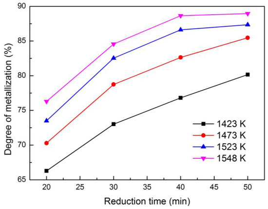
Figure 2.
Effects of time on the degree of metallization of reduced briquettes at different temperatures.
In Figure 2, we observed that the degree of metallization of the reduced samples markedly increased as reduction time was extended. For instance, when the reduction temperature was at 1473 K, the degree of metallization improved from 70.29% to 85.47% with a reduction time of 20–50 min. Moreover, the increasing rate of metallization was gradually decreased as reduction time was extended. In other words, each curve would increase and achieve a stable degree of metallization as reduction time was prolonged in an atmosphere with a relatively sufficient concentration of CO. The time required to reach a stable degree of metallization was shorter at a high reduction temperature than at a low temperature. The vertical comparison among the four curves in Figure 2 reflected that the degree of metallization remarkably increased as reduction temperature increased at a fixed reduction time. For instance, when the reduction time was 40 min, the degree of metallization increased from 76.81% to 88.65% with the reduction temperature ranging from 1423 K to 1548 K.
The reason for this finding was that increasing the reduction time and temperature were beneficial to the reduction process of the reduced composited briquettes. In the initial stage of the reduction, the ore particles and coal particles in the briquettes adequately contacted. The solid–solid reactions [21] and solid–gas reactions [22] would successively occur violently, the iron oxides were stepwise reduced to metal iron in the composited briquettes, and the degree of metallization rapidly increased once metal iron occurred. As the reduction time was extended, the solid–solid reactions gradually disappeared when the solid–gas reactions dominated. Therefore, as the reduction process further progressed, the density of CO and iron oxides gradually decreased, thereby partly slowing the speed of reduction until the equilibrium of reaction was arrived. Increasing the reduction temperature would simultaneously and effectively accelerate the reduction reactions, which were conductive to a high degree of metallization and short time to achieve balancing. In conclusion, extending reduction time or increasing reduction temperature was advantageous to the reduction, and the degree of metallization would be stable as reduction time was continuously extended.
Figure 3 depicts the relationship between the degree of metallization of the reduced briquettes and the reduction temperature for different ore size fractions with a reduction time of 30 min. The degree of metallizations of the reduced briquettes increased as the reduction temperature increased.

Figure 3.
Effects of temperature on the degree of metallization of reduced briquettes at different ore size fractions.
The vertical comparison among the four curves in Figure 3 showed that reducing granularity of iron ore was beneficial to the reduction reactions and the improvement of degree of metallization. For instance, when the ore size fraction decreased to −4.0, −2.0, −1.0, and −0.1 mm at a reduction temperature of 1548 K, the respective corresponding degree of metallizations were 80.18%, 82.54%, 86.53%, and 87.02%.
The main reasons for these changes could be inferred as follows. The surface layer structure of the particles is damaged because of the effect of mechanical forces, such as crush and friction. Particle surface tends to become amorphous, and a large amount of energy is internally stored. As a result, the activation energy decreases, and reduction reactions occur easily. The fine-grained iron ore exhibits a much larger area than the coarse-grained iron ore, thereby improving the adsorption capacity of materials as CO. The fine grains are therefore surrounded by a high density of reducing gas. The other important reason is that the resistance of CO diffusion decreases due to decreased particle size. In this way, reduction reactions are greatly enhanced.
In summary, the granularity of iron ore significantly influences reduction, and decreasing the ore particle size possibly improves the degree of metallization.
3.2. Growth Behavior
To better understand the growth behaviors of the iron particles in reduced briquettes, we observed the SEM images, as presented in Figure 4. The micro-morphology and structure of iron particles reduced at 1423 K at different reduction times of 20, 30, 40, and 50 min. In Figure 4a–d, we assumed that growth behaviors of iron grains of the reduced briquettes underwent the following transformations in coal-based reduction.
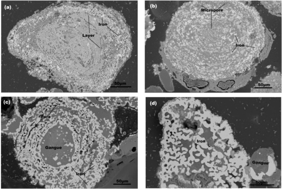
Figure 4.
SEM images of iron particles of reduced briquettes at 1423 K for different reduction times: (a) 20 min; (b) 30 min; (c) 40 min; (d) 50 min.
At the beginning of the reduction, the reduction reactions first occurred in the outer layers as the structure of oolitic hematite was circled by layers. Thereby, iron oxides were reduced to metallic iron in the outer layers. The metallic iron gradually grew into quasi-spherical iron particles based on the principle of minimum surface energy and randomly distributed in the gangue. At this stage, almost no agglomeration of iron grains occurred (Figure 4a). As reduction continued, the layered structure was destroyed. Then iron oxides in an oolitic particle were gradually reduced layer-by-layer from outside to inside (Figure 4a–b). Many micropores were formed in the reduction process, which either accelerated the diffusion of reducing gas or expedited the outside-to-in reduction progress. At the same time, the fresh metallic iron and small iron grains gradually attached to the large ones and grew (Figure 4b). With reduction time, the layered structure was completely destroyed, and most ore particles became porous and cracked. An increasing number of iron grains were generated and moved together to stack into iron particle cluster, which were bead-like or chained iron particles as shown from the cross section (Figure 4c). With agglomeration and consolidation, small particles gradually decreased and even disappeared. These bead-like or chained iron particles were further sintered. Many large iron particles were formed and took the shapes of quasi-spherical, blocky, and clavate when viewed from cross-section (Figure 4d). In the last stage, many iron grains were sintered together to form an accumulated iron particle cluster. The boundaries among the iron grains were gradually diluted until they disappeared (Figure 5).
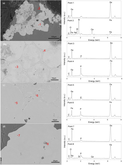
Figure 5.
SEM-EDS results for the fusion process of boundaries in an accumulation iron particle group at 1548 K for different reduction times: (a) 20 min; (b) 30 min; (c) 40 min; (d) 50 min.
To better illustrate the fusion of boundaries in an accumulated iron particle cluster, we obtained some images of iron particle clusters at 1548 K for various times of 20–50 min. The SEM images of the iron grains and boundaries are illustrated in Figure 5a–d, whereas the corresponding EDS analyses for each image are presented in points 1–8 and Table 4. From the analyses of points 1−8, the predominant element of bright particles was Fe, and the gray parts were mainly based on Si, Al, O, and Ca, indicating that the bright particles were metallic iron, and the other parts were slags. Table 4 presents the concentrations of C, P, and Fe.
Table 4.
Results of EDS analysis for metal phase.
As shown in Figure 5a, the metallic iron of iron grains diffused quickly at a high temperature of 1548 K, and the iron particles in the reduced briquettes grew. Some iron grains were in contact with each other. Many boundaries among the contiguous iron grains appeared, and the connection section of iron grains was weak in this stage. Subsequently, an accumulated iron particle cluster, which was irregularly combined by quasi-spherical iron grains, formed and became embedded in slags. In Figure 5b, the diffusion of metallic iron continued as reduction time was extended. The iron grains in the accumulated iron particle cluster sintered together and closely united. Some boundaries among the united grains were apparent. Small amounts of C and P dissolved in the solid solution with the iron (Table 4). The contents of C and P in the boundaries of iron grains were much higher than those in the interior iron grains (points 3–4), which possibly hindered the fusion of iron grains from being a homogeneous iron particle. During the fusion of iron grains, C and P also converted from a slag phase into a metal phase, and based on the standard Gibbs free energy changes (ΔGθ), we considered that Reactions (5) and (6) occurred during fusion (Table 4) [3]. As shown in Figure 5c, the iron grains in the accumulated iron particle cluster further fused after the reduction time was further extended to 40 min. C and P diffused from the boundaries to the grain interior [23]. By contrast, Fe diffused into the boundary (points 3–6). The difference between the boundary and the interior of iron grains gradually decreased (Table 4).
3Fe + C = Fe3C
ΔGθ = [17685.45 − 15.11 (T/K)]
ΔGθ = [17685.45 − 15.11 (T/K)]
3Fe + P = Fe3P
ΔGθ = [−154,925.43 + 36.60 (T/K)]
ΔGθ = [−154,925.43 + 36.60 (T/K)]
As illustrated in Figure 5d, the boundaries gradually faded and disappeared as reduction and diffusion continuously occurred. A bright and homogeneous iron particle was formed. At the same time, some tiny slag inclusions were embedded in the large iron particle. However, the EDS result indicated that the inclusions were based on Fe–O–Si–Ca–P (point 8). These compound inclusions were disregarded in this study.
3.3. Size Characterization of Iron Particles
3.3.1. Effect of Reduction Temperature on Iron Particle Size
Figure 6 shows that the mean size, cumulative frequency distribution, and characteristic particle size at various temperatures for 30 min. Iron particle size markedly increased as the reduction temperature increased possibly because increasing reduction temperature could accelerate the reduction reactions of iron oxide and the diffusion of metallic iron. In Figure 6a, the mean size of metallic iron particles obviously increased as reduction temperature increased, revealing that increasing the reduction temperature was conducive to the growth of metallic iron particles. The two stages were analyzed according to the growth rate as temperature increased. When the reduction temperature increased from 1423 K to 1473 K, the mean size of metallic iron particles slowly grew from 19.47 μm to 31.11 μm. The growth rate of metallic iron particles in this stage might be mainly controlled by the reduction reaction rate of iron oxide to metallic iron. When the reduction temperature increased from 1473 K to1548 K, the mean size of metallic iron particles quickly grew from 31.11 μm to 407.33 μm. The growth rate of metallic iron particles in this stage might mainly be controlled by the diffusion rate of metallic iron. Figure 6b shows that the cumulative frequency evidently increased with iron particle size, especially when the particle size was small. Small particles constituted a large proportion, whereas large particles accounted for a small proportion. The curves of cumulative frequency systematically shifted rightward as reduction temperature improved, reflecting that the number of large particles increased and iron particles grew gradually as the reduction temperature increased. For instance, the D50 and D80 of iron particles at a fixed reduction time of 30 min increased from 8.47 and 15.32 μm to 60.62 and 147.05 μm, respectively, as the reduction temperature increased from 1423 K to 1548 K (Figure 6c).
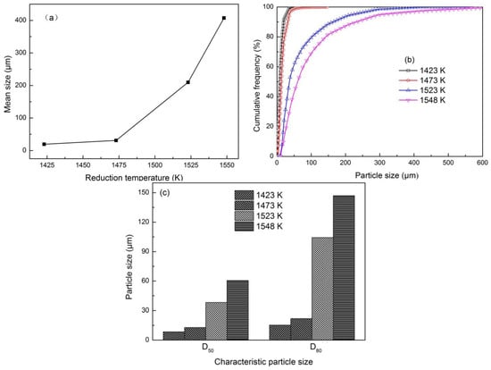
Figure 6.
Effect of reduction temperature on iron particle size at reduction time of 30 min and −2 mm oolitic hematite particle size: (a) Mean size; (b) cumulative frequency distribution; (c) characteristic particle size.
3.3.2. Effect of Reduction Time on Iron Particle Size
Figure 7 shows the mean size, cumulative frequency distribution, and characteristic particle size as the reduction time was extended at a fixed temperature of 1423 K. Similarly, the iron particle size evidently increased as the reduction time was extended. Figure 7a illustrates that the mean size of metallic iron particles gradually increased as the reduction time was extended, indicating that extending reduction time helped generate additional metallic iron and its diffusion. For instance, the mean size increased from 11.81 μm to 25.19 μm as the reduction time was prolonged from 20 min to 50 min. From Figure 7b, the cumulative frequency also increased with iron particle size. When the reduction time was extended from 20 min to 50 min, the curves of cumulative frequency consecutively shifted rightward, implying that the number of large particles increased, and iron particles grew gradually as the reduction time was prolonged. For instance, D50 and D80 of iron particles at a fixed reduction temperature of 1423 K increased from 5.16 and 8.95 μm to 13.96 and 24.15 μm, respectively, as the reduction time was extended from 20 min to 50 min (Figure 7c).
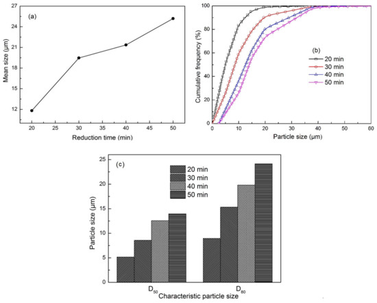
Figure 7.
Effect of reduction time on iron particle size at 1423 K and −2 mm oolitic hematite particle size: (a) Mean size; (b) cumulative frequency distribution; (c) characteristic particle size.
3.3.3. Effect of Ore Size Fraction on Iron Particle Size
Figure 8 illustrates the mean size, cumulative frequency distribution, and characteristic particle size with different ore size fractions at constant 1523 K and 30 min. Iron particle size increased with reducing ore size fraction. The reason might be concluded that reducing ore size fraction accelerated the reduction reactions and increased the degree of metallization (Figure 3). Adding that more surface of fine ore fully touched with reducing gas, and much more iron nuclei were formed in the ore particle surface. Figure 8a shows that the mean size of iron particles decreased with increasing ore size fraction, which demonstrated that increasing particle size of raw ore was a barrier to the growth of iron particles. For instance, the mean size decreased from 436.43 μm to 200.88 μm as the ore size fraction increased from −0.1 mm to −4.0 mm. In Figure 8b, the cumulative frequency evidently increased with iron particle size. We also found that the curves of cumulative frequency successively shifted to the right as the ore size fraction decreased, indicating that the number of large particles increased and iron particles grew effectively as the ore size fraction decreased. For instance, D50 and D80 of iron particles increased from 33.28 and 90.65 μm to 93.78 and 209.28 μm, respectively, as the ore size fraction decreased from −4.0 mm to −0.1 mm (Figure 8c).
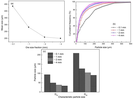
Figure 8.
Effect of ore size fraction on iron particle size at 1523 K and 30 min: (a) Mean size; (b) cumulative frequency distribution; (c) characteristic particle size.
Increasing reduction temperature, extending reduction time, or decreasing ore size fraction could accelerate the growth of iron particles. Large iron particles were formed at a high temperature, long time, and fine ore granularity.
4. Conclusions
In this study, the oolitic hematite–coal composite briquettes were conducted by coal-based reduction at various reduction temperatures, reduction times, and ore size fractions. The degree of metallization, microstructure, and particle size characteristics were investigated to further reveal the growth behavior and size characteristics of metallic iron particles. Based on the results, the following conclusions could be drawn:
- (1)
- Reduction temperature, time, and ore size fraction strongly influenced the reduction. The degree of metallization increased as the reduction temperature was increased, the reduction time was extended, or the ore size fraction was decreased until the equilibrium of reaction was achieved.
- (2)
- Iron oxide was reduced to metallic iron from outer to inner layers in an ooid. At the same time, the generated metallic iron diffused together and gradually grew into spherical-like iron particles with a random distribution in the gangue. As reduction continued, iron grains agglomerated, and iron particle clusters were formed by taking the shapes of quasi-spherical, chained, blocky, and clavate when they were viewed from the cross section. The boundary sections among iron grains continually faded and disappeared, and an iron particle with increased size and homogeneity was formed.
- (3)
- The reduction temperature, reduction time, and ore size fractions significantly influenced the growth of iron particles. The mean size of iron particles increased, and the iron particles grew as reduction temperature was increased, reduction time was extended, or ore size fraction was decreased.
Acknowledgments
This work was financially supported by the National Natural Science Foundation of China (Nos. 51604063). The authors wish to thank the BGRIMM for their cooperation in conducting the investigation.
Author Contributions
Yanfeng Li and Yuexin Han conceived and designed the experiments; Yanfeng Li performed the experiments; Yanfeng Li and Yongsheng Sun analyzed the data; Peng Gao, Yanjin Li, and Guichen Gong contributed reagents/materials/analysis tools; Yanfeng Li wrote the paper.
Conflicts of Interest
The authors declare no conflict of interest.
References
- Maynard, J.B.; Van Houten, F.B. Descriptive Model of Oolitic Ironstones, Developments in Mineral Deposit Modeling; U.S. Geological Survey: Washington, DC, USA, 2004; pp. 39–43.
- Li, S.F.; Sun, Y.S.; Han, Y.X.; Shi, G.Q.; Gao, P. Fundamental research in utilization of an oolitic hematite by deep reduction. Adv. Mater. Res. 2011, 158, 106–112. [Google Scholar] [CrossRef]
- Gao, P.; Li, G.F.; Han, Y.X.; Sun, Y.S. Reaction behavior of phosphorus in coal-based reduction of an oolitic hematite ore and pre-dephosphorization of reduced iron. Metals 2016, 6, 82. [Google Scholar] [CrossRef]
- Song, S.X.; Campos-Toro, E.F.; Zhang, Y.M.; Lopez-Valdivieso, A. Morphological and mineralogical characterizations of oolitic iron ore in the Exi region, China. Int. J. Miner. Metall. Mater. 2013, 20, 113–118. [Google Scholar] [CrossRef]
- Ripke, S.J.; Kawatra, S.K. Effect of cations on unfired magnetite pellet strength. Miner. Metall. Process. 2003, 20, 153–159. [Google Scholar]
- Youssef, M.A.; Morsi, M.B. Reduction roast and magnetic separation of oxidized iron ores for the production of blast furnace feed. Can. Metall. Q. 1998, 37, 419–428. [Google Scholar] [CrossRef]
- Tong, X.; Li, Y.S.; Zhou, Q.H.; Rao, F.; Cui, Y.Q. New test research on beneficiation of refractory oolitic hematite. Eng. Sci. 2005, 7, 323–326. [Google Scholar]
- Liu, S.; Wang, W.; Zhang, M.; Wen, S. Beneficiation of a low grade hematite-magnetite ore in China. Miner. Metall. Process. 2014, 31, 136–142. [Google Scholar]
- Li, Y.L.; Sun, T.C.; Kou, J.; Guo, Q.; Xu, C.Y. Study on phosphorus removal of high-phosphorus oolitic hematite by coal-based direct reduction and magnetic separation. Miner. Process. Extr. Metall. Rev. 2014, 35, 66–73. [Google Scholar] [CrossRef]
- Sun, Y.S.; Gao, P.; Han, Y.X.; Ren, D.Z. Reaction behavior of iron minerals and metallic iron particles growth in coal-based reduction of an oolitic iron ore. Ind. Eng. Chem. Res. 2013, 52, 2323–2329. [Google Scholar] [CrossRef]
- Tang, H.Q.; Qin, Y.Q.; Qi, T.F. Phosphorus removal and iron recovery from high-phosphorus hematite using direct reduction followed by melting separation. Miner. Process. Extr. Metall. Rev. 2016, 37, 236–245. [Google Scholar] [CrossRef]
- Wen, Y.; Sun, T.C.; Cui, Q.; Xu, C.Y.; Kou, J. Effect of coal type on the reduction and magnetic separation of a high-phosphorus oolitic hematite ore. ISIJ Int. 2015, 55, 536–543. [Google Scholar]
- Kou, J.; Sun, T.C.; Li, Y.L.; Cao, Y.Y. Studies on the effects of particle size in direct reduction roasting of limonite ores. Adv. Mater. Res. 2012, 402, 546–551. [Google Scholar] [CrossRef]
- Sun, Y.S.; Han, Y.X.; Gao, P.; Wang, Z.H.; Ren, D.Z. Recovery of iron from high phosphorus oolitic iron ore using coal-based reduction followed by magnetic separation. Int. J. Miner. Metall. Mater. 2013, 20, 411–419. [Google Scholar] [CrossRef]
- Huang, D.B.; Zong, Y.B.; Wei, R.F.; Gao, W.; Liu, X.M. Direct reduction of high-phosphorus oolitic hematite ore based on biomass pyrolysis. J. Iron Steel Res. Int. 2016, 23, 874–883. [Google Scholar] [CrossRef]
- Li, G.H.; Zhang, S.H.; Rao, M.J.; Zhang, Y.B.; Jiang, T. Effects of sodium salts on reduction roasting and Fe-P separation of high-phosphorus oolitic hematite ore. Int. J. Miner. Process. 2013, 124, 26–34. [Google Scholar] [CrossRef]
- El-Geassy, A.A. Influence of doping with CaO and/or MgO on stepwise reduction of pure hematite compacts. Ironmak. Steelmak. 1999, 26, 41–52. [Google Scholar] [CrossRef]
- El-Geassy, A.A.; Abdel Halim, K.S.; Bahgat, M.; Mousa, E.A.; El-Shereafy, E.E.; El-Tawil, A.A. Carbothermic reduction of Fe2O3/C compacts: Comparative approach to kinetics and mechanism. Ironmak. Steelmak. 2013, 40, 534–545. [Google Scholar] [CrossRef]
- Christopher, M. Science of empirical design in mining ground control. Int. J. Min. Sci. Technol. 2016, 26, 461–470. [Google Scholar]
- Wei, H.; He, Y.Q.; Shi, F.N. Breakage and separation mechanism of ZGM coal mill based on parameters optimization model. Int. J. Min. Sci. Technol. 2014, 24, 285–289. [Google Scholar] [CrossRef]
- Chen, L.Y.; Bao, J.H.; Kong, L.; Combs, M.; Heather, S.N.; Fan, Z.; Liu, K.L. The direct solid-solid reaction between coal char and iron-based oxygen carrier and its contribution to solid-fueled chemical looping combustion. Appl. Energy 2016, 184, 9–18. [Google Scholar] [CrossRef]
- Maya, J.C.; Janna, F.C. Novel model for non-catalytic solid-gas reactions with structural changes by chemical reaction and sintering. Chem. Eng. Sci. 2016, 142, 258–268. [Google Scholar] [CrossRef]
- Yu, W.; Tang, Q.Y.; Chen, J.A.; Sun, T.C. Thermodynamic analysis of the carbothermic reduction of a high-phosphorus oolitic iron ore by FactSage. Int. J. Miner. Metall. Mater. 2016, 23, 1126–1132. [Google Scholar] [CrossRef]
© 2018 by the authors. Licensee MDPI, Basel, Switzerland. This article is an open access article distributed under the terms and conditions of the Creative Commons Attribution (CC BY) license (http://creativecommons.org/licenses/by/4.0/).