Article

Preserving Flake Size in an African Flake Graphite Ore Beneficiation Using a Modified Grinding and Pre-Screening Process

1
School of Resources and Environmental Engineering, Wuhan University of Technology, Luoshi Road 122, Wuhan 430070, China
2
Hubei Province Key Laboratory for Processing of Mineral Resources and Environment, Luoshi Road 122, Wuhan 430070, China
*
Authors to whom correspondence should be addressed.
Minerals 2017, 7(7), 115; https://doi.org/10.3390/min7070115
Submission received: 7 June 2017 / Revised: 30 June 2017 / Accepted: 2 July 2017 / Published: 4 July 2017

Abstract

:
As the high value and the scarcity of large-flake graphite ore resources, it is in the best interest to maximize the amount of large flakes and minimize any processing that will reduce flake sizes. In the study, the mineralogy of an African graphite ore was estimated using X-ray diffraction (XRD), X-ray fluorescence (XRF), and optical microscope analyses. The results indicated that it was a heavily weathered large flake graphite ore and the main gangue minerals were quartz and kaolinite. The graphite flakes were thick, bent, and fractured, and some clay minerals were embedded into the graphite interlayer, which made it difficult to prevent the large flakes from being destroyed using mechanical grinding methods. An approach of steel rod coarse grinding and pebble regrinding effectively reduced the destruction of graphite flakes and improved the grinding efficiency. In addition, comparing with the conventional process, a pre-screening process was applied and the content of large flakes in the final concentrate was significantly improved.

1. Introduction

Graphite is an irreplaceable raw material and a widely used non-metallic material in many industries such as foundry facings, refractories, lubricants, pencils, batteries, brake linings, bearings, conductive coatings, and crucibles due to its unique physical and chemical properties [1,2]. In general, natural graphite is classified as three varieties: crystalline flake, vein, and amorphous, according to the difference of crystalline morphology [3,4,5,6]. Due to the strong floatability of graphite, flotation is the most commonly used method of graphite beneficiation. Among them, crystalline flake graphite has the best floatability, followed by vein graphite; amorphous graphite has the poorest floatability [3,6,7,8,9,10]. Therefore, flake graphite can be easily purified by flotation. However, “run-of-mine” flake graphite is only available in a purity range of 80–98% using froth floatation, to achieve flake above 98%, other methods such as chemical-based and thermal-based methods must be used subsequent to floatation [11,12,13,14].
Flake graphite, as indicated by the name, has a flaky morphology. Most flake graphite is formed in a high-grade (high-temperature and -pressure), metamorphic geologic environment by the heat and pressure metamorphism of dispersed organic material [11,12]. The flake graphite of +150 μm in diameter is defined as large flake graphite, correspondingly, that of −0.150 μm in diameter is considered as fine flake graphite [5,6]. The large flake graphite has more significant industrial value than the small one because of some exclusive properties, such as excellent lubricity and thermal conductivity [11]. For instance, the manufacture of graphite crucible and expanded graphite must use large flake-graphite as the raw material. However, high-quality graphite resources that contain large graphite flakes are becoming increasingly scarce and some flake graphite ores do not contain any large flakes. Furthermore, large-flake graphite can only be produced from natural graphite ores, but cannot be synthesized using modern industrial technology [11,15]. Once the large flakes are destroyed, they cannot be restored.
Generally, the process of large flake graphite ore should be simpler than that of the fine ore because of its superior floatability. However, considering the high value of large graphite flakes, the process is normally more demanding, and the priority is to avoid overgrinding and to maximize flake size [16]. Any mechanical process done to the ore, or the flake, will potentially destroy the flake [12]. Therefore, grinding is considered to be the main contributor to the destruction of large flakes because the graphite flakes of low-hardness are vulnerable to damage [17].
There are two main factors affecting the yield of large-flake graphite in grinding operation. First, the miscellaneous grinding in the process causes unnecessary overgrinding to the liberated graphite flakes; the other factor is the abrasive action of harder gangue minerals, such as quartz and pyroxene, which have sharp angularity to the graphite flakes. Therefore, in conventional flake graphite ore processing, a multistage grinding-flotation process is always used to prevent large flakes from being heavily destroyed [18]. This process can ensure the dissociated impurities from grinding process to be removed out promptly by the subsequent flotation process. As a result, the content of hard gangue minerals in the following grinding process is decreased; consequently, the damage of graphite flakes is diminished.
However, the large-flake amount of the conventional multistage grinding process is not always satisfied because the flakes are still reground throughout the process. Some studies have been conducted to ameliorate the grinding process to avoid overgrinding. Some studies on grinding medium [17,18] indicate that rod milling, in which the grinding is affected by line contact, is more favorable for retaining the flakes than those point-contacted mills, like ball milling [19,20]. In addition, some new grinding processes, such as vibration milling [18] and stirred milling [21], are more efficient at reducing the breakage of graphite flakes than the traditional tumbling milling. With regard to the flotation process, flash flotation [22,23,24] and graded grinding-flotation [25] are the most effective approaches. The flash flotation process, which is widely applied in metal ore processing [26], is a method of fast-flotation using the flotation rate differences between the dissociated monomer and the combination. The floatability of the dissociated graphite monomer is generally better than the combination. Accordingly, this part of graphite is floated in advance and excluded from the following regrinding process. A graded grinding-flotation process separates the qualified large flakes promptly after each flotation process because the larger flakes normally correspond to the higher grade [27]. However, these aforementioned approaches are either reflect a complex process or are of low efficiency. To find a new combination of grinding media and a pre-screening process may effectively simplify the process and recover large graphite particles.
In the work, XRD, XRF, and optical microscopy were used to analyze the composition, morphology of the graphite ore, and the size distribution of the graphite flakes. The optimum experimental parameters of coarse grinding and first regrinding were determined using a series of single-factor experiments. A modified grinding and pre-screening process was proposed to preserve the content of large graphite flakes based on the symbiotic way of the graphite with the gangue minerals.

2. Material and Methods

2.1. Materials

The large-flake graphite ore, taken from Tulla Province, Madagascar, was crushed using a double toggle jaw crusher (SP-60 × 100) (Rock, Wuhan, China). Then, some representative samples were obtained and ground using an XPZXPZ (RK/XPM-Φ120 × 3) (Rock, Wuhan, China) to study the mineralogical and chemical compositions, and the other samples were used for the grinding and flotation tests.
The X-ray fluorescence (XRF) analysis for the raw ore is given in Table 1, which shows that the main compositions were SiO2, Al2O3, Fe2O3, SO3, and K2O, accounting for 60.93%, 13.21%, 4.13%, 4.01%, 0.94%, and 0.57%, respectively, and the total loss was 15.22%. In addition, the raw ore was analyzed with the Chinese standard method (GB/T3521-2008), assaying 7.59% fixed carbon (FC).
Figure 1 shows the XRD pattern of the raw ore, and the contents of the gangue minerals are summarized in Table 2. The main gangue minerals associated in the graphite ore were quartz, kaolinite, muscovite, and fibrolite, accounting for 50%, 23%, 8%, and 5%, respectively.

2.2. Analysis Methods

Chemical compositions of the raw ore were determined using an X-ray fluorescence spectrometer (AXIOS, PANalytical B.V., Almelo, The Netherlands). Phase compositions of the raw ore were identified using an Advance X-ray diffractometer (D8, Bruker, Karlsruhe, Germany) with Cu Kα radiation (k = 1.5406 nm) at 40 kV and 100 mA. The mineralogy of the raw ore was observed using an optical microscope (A2 pol, Leica, Wetzlar, Germany). More than thirty blocks of rough crushed ore were chosen randomly to prepare polished sections and thin sections for the study. SEM images of the final concentrate were obtained using a scanning electron microscope (JSM-IT300). The FC content (wt %) was analyzed based on the Chinese standard method (GB/T3521-2008).

2.3. Experimental Tests

The raw ore was divided into 300 g each for testing. Before flotation, the sample was first rough ground in a RK/BM-2.0 L tube mill at a revolving speed of 210 r/min, either steel ball, steel rod or pebble was selected as the grinding medium. Bench-scale laboratory flotation tests were carried out in a series of 0.5–1.0 L RK/FD mechanically agitated flotation machines at an impeller speed of 2000 rpm, and the regrinding was performed in a RK/BM-1.0 L tube mill. The parameters of coarse grinding and regrinding media are shown in Table 3. The size distributions of the grinding products and the concentrates were obtained using a Taylor standard vibrating sieve group. Kerosene and terpenic oil, which were used as the collector and frother, respectively, were purchased from Kermel Chemical Reagent Co., Ltd. (Kermel, Tianjin, China). All reagents were of analytical grade and directly used without further purification.

2.4. Grinding Damage Coefficient

To evaluate the damage effect of the grinding operation to graphite flakes, the yield and FC content of the concentrate were analyzed under the same flotation conditions. Basically, a higher yield and a higher FC content of +150 μm size fraction concentrate correspond to better grinding effect. In addition, the grinding effect should also be related to the concentrate recovery because a higher recovery indicates better liberation among the graphite and gangue. Therefore, the grinding damage coefficient L can be calculated using the following equation. A smaller value of L corresponds to weaker destruction of the grinding on graphite flakes:
L   =   γ 0 γ c × γ 1 β 1 β 0   ×   1 α c
where L is the grinding damage coefficient (%); γ0 is the yield of the +150 μm product before regrinding (%); γc is the yield of the concentrate after regrinding (%); γ1 is the yield of the +150 μm product in the concentrate after regrinding (%); αc is the recovery of the concentrate after regrinding (%); and β0 and β1 are the FC contents of the +150 μm product in the concentrate before and after regrinding (%).

3. Results and Discussion

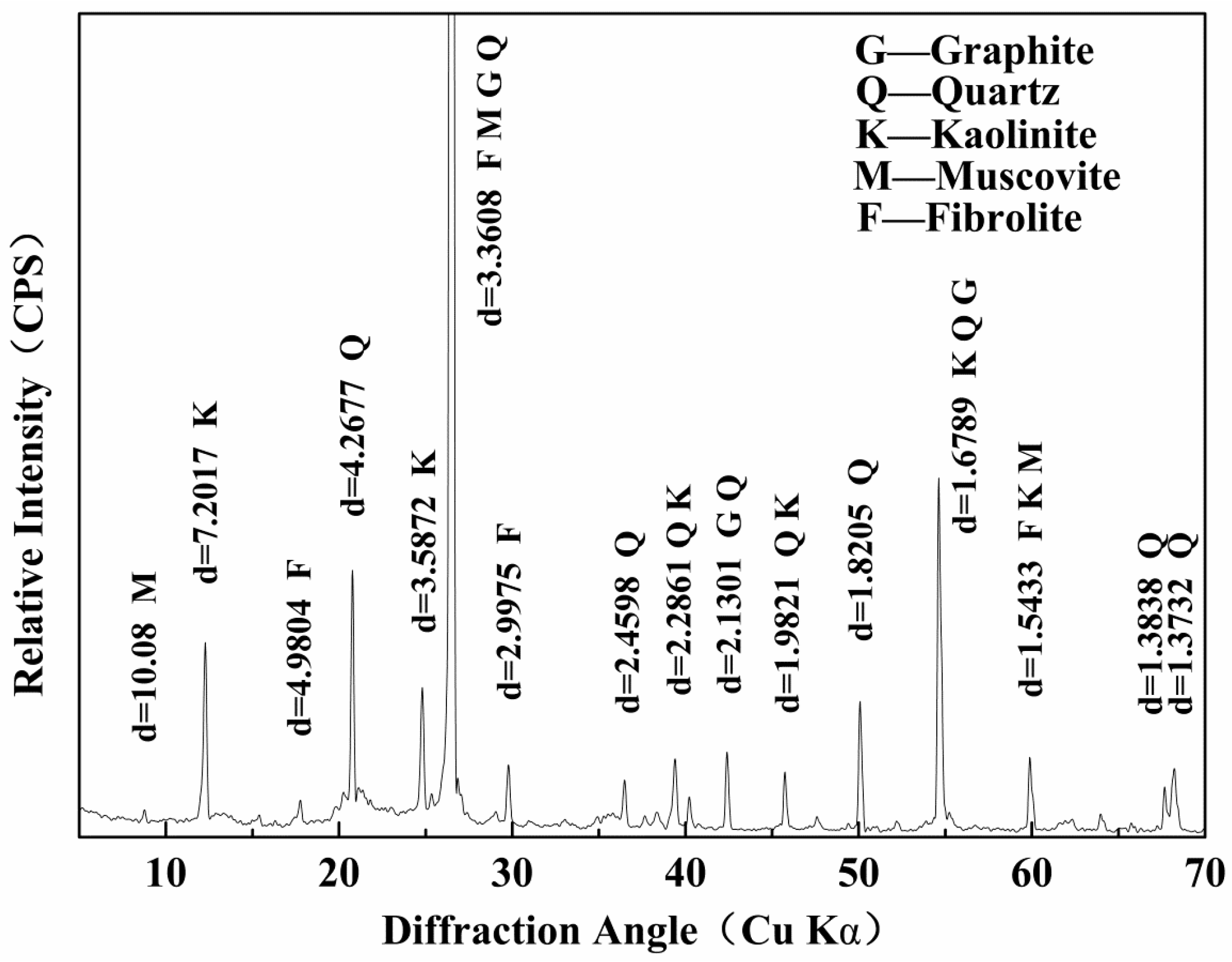
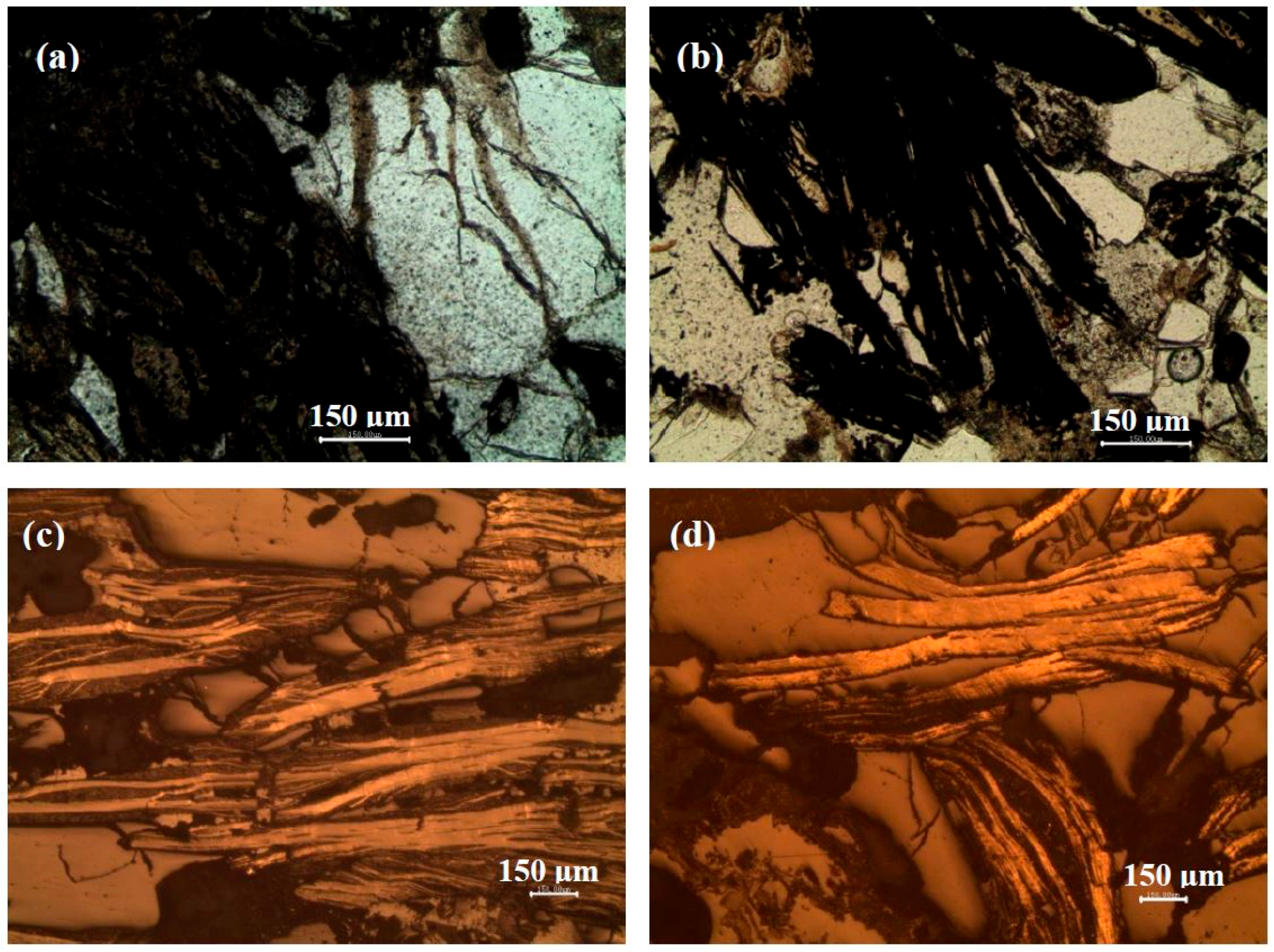
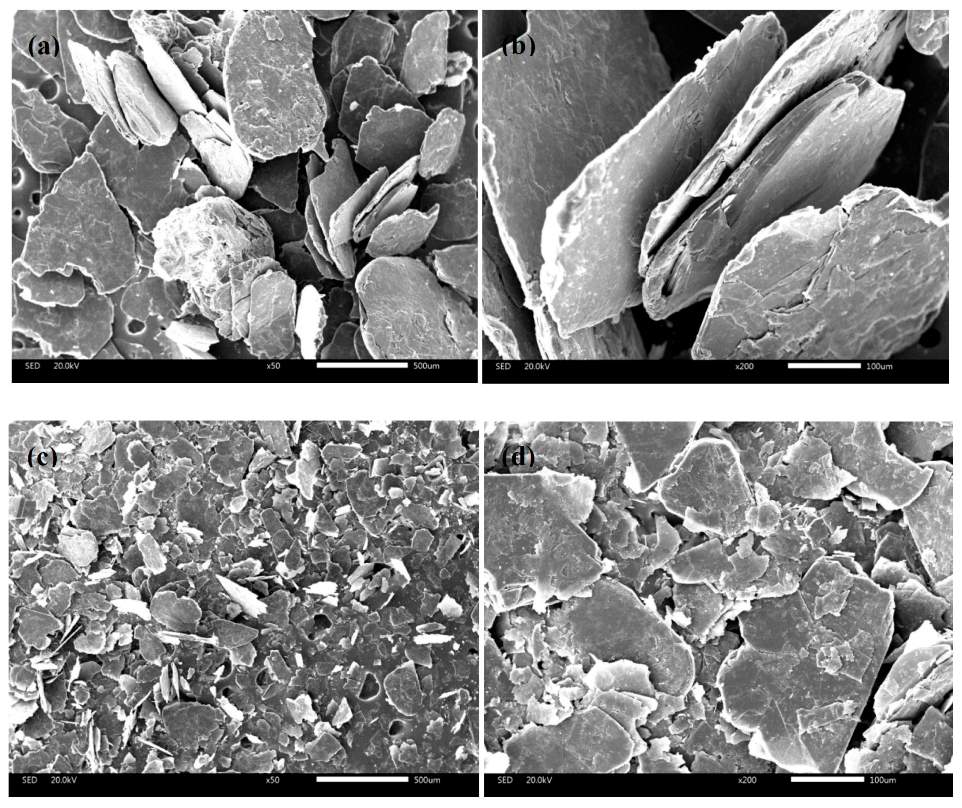
3.1. Mineralogy Study

The morphology of the raw ore was observed using an optical microscope, and the liberation characteristics and the images of graphite flakes are shown in Table 4 and Figure 2, respectively. Table 4 shows that the graphite particles size distribution is uniform and approximate half amount of the particles are large flakes. Moreover, most graphite can be classified as large-flake graphite, according to the 95.55% cumulative distribution rate of the +150 μm size fraction. As a result, it is of great necessity to preserve the large flakes of this graphite ore in the beneficiation process.
Figure 2a,b show that the graphite stripes (the black part) are of directional distribution and the thick stripes are distributed into the heavily weathered clay minerals. This part of graphite can be easily dissociated from the gangue minerals using crushing and grinding. However, Figure 2c,d show that most graphite stripes (the bright part) exhibit either bended or fractured shape, and some gangue minerals are trapped between adjacent flakes. As a result, it was difficult to fully achieve liberation of the graphite and gangue minerals without destroying the large flakes using mechanical methods, which also led to a reduction of the FC content and recovery of the final concentrate.

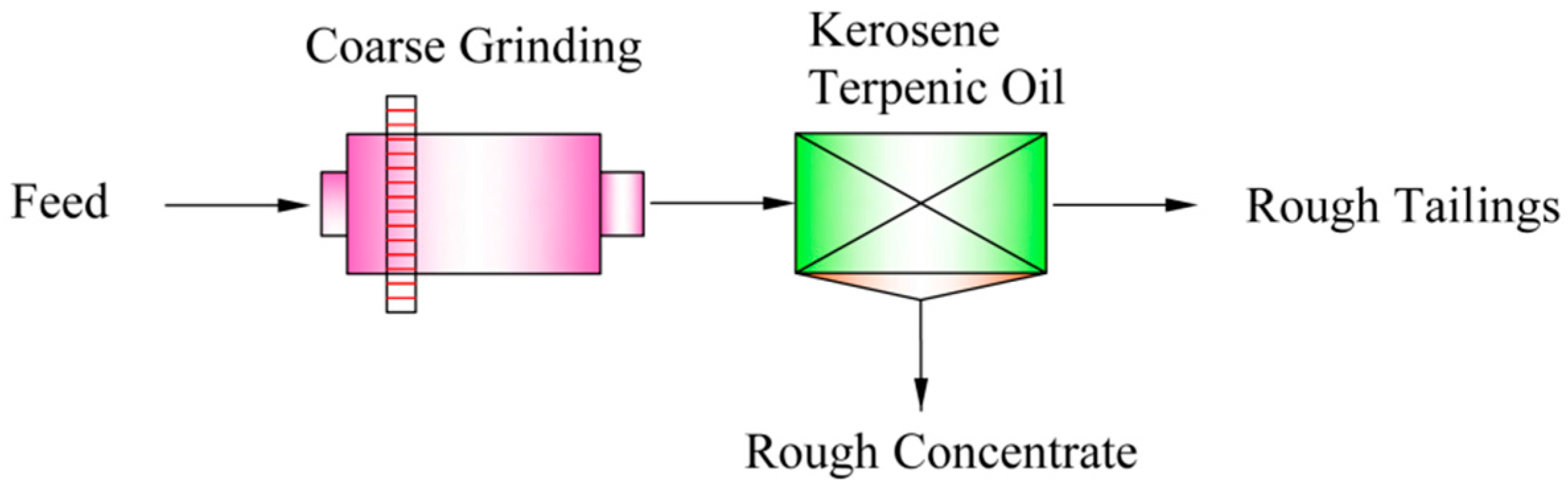
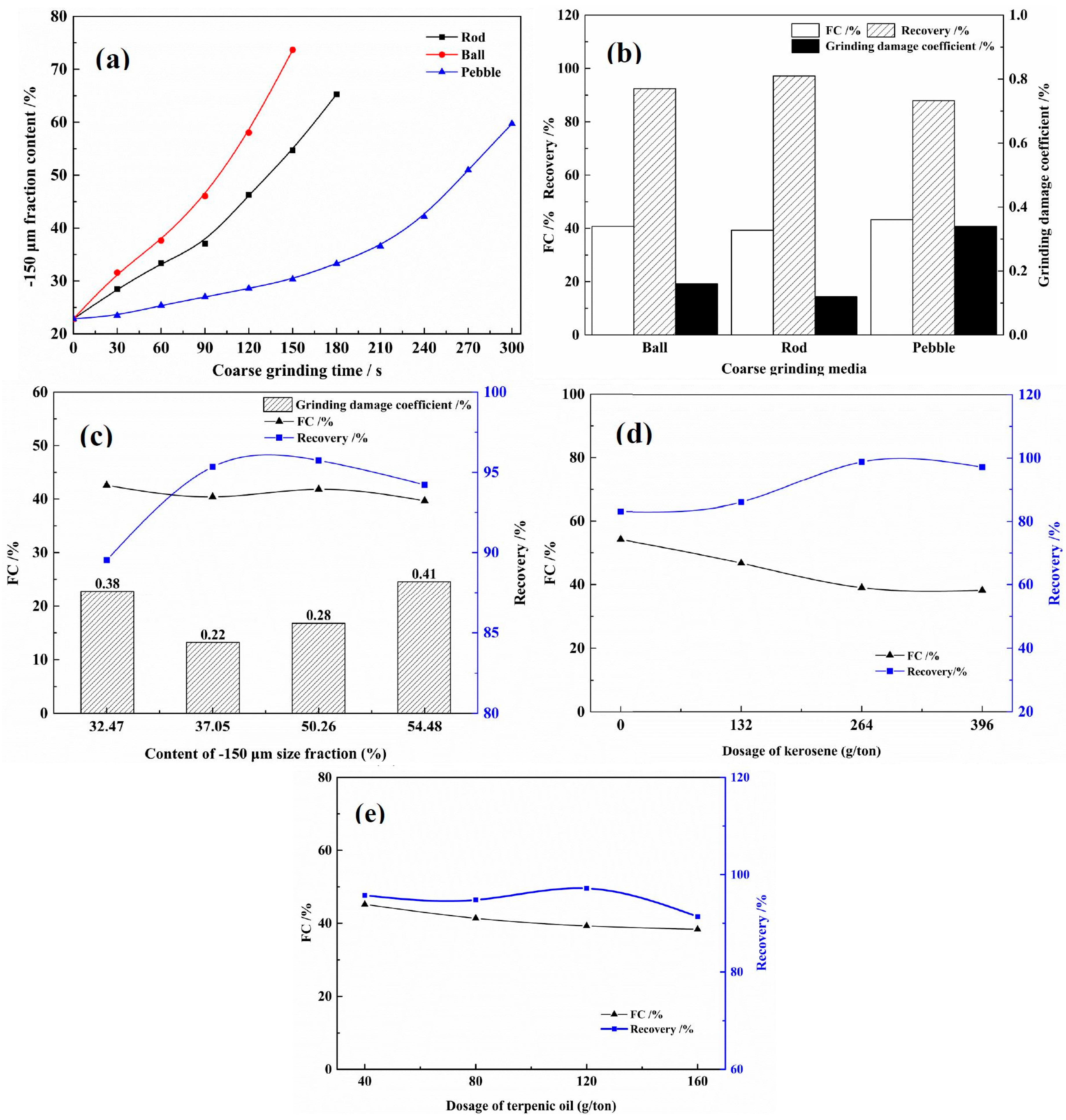
3.2. Coarse Grinding

The coarse grinding tests of the raw ore were conducted as shown in Figure 3. The experimental parameters, such as coarse grinding medium and grinding fineness of the raw ore, dosage of kerosene and terpenic oil were also considered, and the relevant results are shown in Figure 4.
Grinding media and grinding fineness significantly contribute to the destruction of large graphite flakes and the quality of the final concentrate [28,29]. Figure 4a shows the grinding curves of the three different grinding media (rod, ball, and pebble). As seen, the pebble mill is much more time-consuming to achieve a similar grinding fineness compared with the ball and rod mill. The ball medium is the most destructive, followed by the rod medium, and pebble has the lowest intensity of the media for the coarse grinding. To evaluate the grinding effects of those three coarse grinding media, a similar coarse grinding fineness of −150 μm size fraction at approximately 40.0% was chosen according to the grinding curves in Figure 4a. Figure 4b compares the FC content and recovery of the rough concentrates and the grinding damage coefficient of the grinding media. As seen, the rough concentrate recovery is the highest and the grinding damage coefficient is the lowest using rod as the coarse grinding medium because the line contact among the rods will give priority to crush the coarse particles and therefore, the over-crushing of graphite flakes is slight [30,31]. Generally, large-flake graphite is easier to dissociate from gangue minerals from the joint surface as a function of the shear-force based grinding method like rod mill [32]. On the contrary, the rough concentrate recovery using the pebble mill is the lowest, which indicates that the pebble mill was not capable of fully dissociating the graphite with some hard gangue minerals, like quartz in coarse grinding. Therefore, the optimum coarse grinding medium was rod.
The coarse grinding fineness of the rod mill was investigated and the results are shown in Figure 4c. A relatively higher grinding damage coefficient of 0.38% and a lower recovery of under 90.0% are observed at the initial coarse grinding fineness of −150 μm size fraction at 32.05%. This is mainly because of the undesirable liberation among the graphite and gangue particles, which causes part of the large graphite flakes reported to the tailings. When the grinding fineness is increased, the recovery of coarse concentrate increases and then levels off, whereas an initial decrease and further increase of the grinding damage coefficient is observed. The increasing grinding damage coefficient indicates that the graphite flakes were damaged with the increasing grinding intensity. Moreover, a further increase the content of −150 μm size fraction will surely consume more energy and reagent [33]. Comparing the results, the optimum coarse grinding fineness was adopted at −150 μm size fraction accounting for 37.05%.
In spite of the high natural hydrophobicity of large-flake graphite, a collector and frother were also used to ameliorate the flotation process and improve the FC content and recovery of the final concentrate [11]. Figure 4d,e show that the optimum FC content and recovery of the rough concentrate were obtained when the dosage of collector kerosene and frother terpenic oil were 264 g/ton and 120 g/ton, respectively. All of these rough conditions were applied for the further tests.

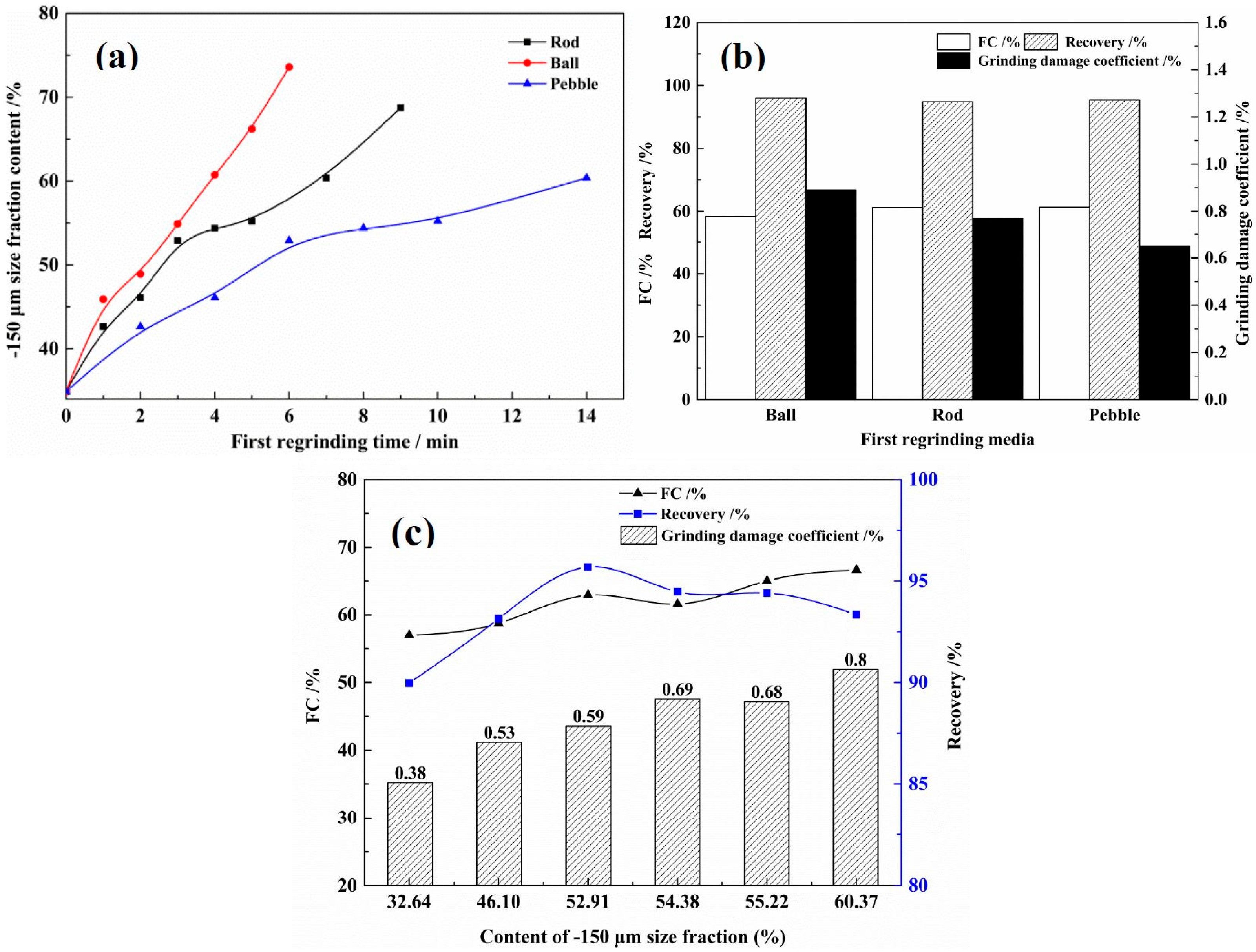
3.3. First Regrinding

The FC content of the rough concentrate was approximately 40%, and the main gangue minerals such as the weathered clays and liberated quartz had already reported to the rough tailings. Most graphite particles in the rough concentrate were in partial contact with some gangue or directly exposed, which made the graphite flakes easily to crush and grind. The gangue contained had a detrimental effect on the graphite flakes and must be removed as soon as possible. A rational choice of following regrinding medium and regrinding fineness should not only contribute to the further liberation of the graphite and gangue minerals, but also effectively prevent the graphite flakes from being severely destructed. The first regrinding tests of the raw ore were conducted as shown in Figure 5. The experimental parameters, such as regrinding media and regrinding fineness were considered, and the relevant results are shown in Figure 6.
Figure 6a shows the mill curves of the three different regrinding media. Unlike coarse grinding, before which the graphite and gangue minerals were not well liberated, the majority of gangue minerals had already reported to the coarse tailings before the first regrinding process. The gangue minerals remaining in the coarse concentrate were either mechanically attached to the surface of flakes or trapped between adjacent flakes. Therefore, the distinction of regrinding curves among these three media, as shown in Figure 6a, is much slighter than the coarse grinding curves. Figure 6b compares the FC content and recovery of the concentrate and the grinding damage coefficient of the three regrinding media under an identical fineness of −150 μm size fraction at approximately 46.0% according to the results of Figure 6a. The FC content and recovery of the three concentrates are all achieved the similar values of approximately 60% and 95%, respectively. The grinding damage coefficient is the lowest using pebble as the first regrinding medium. However, the rods and balls were too intense for the regrinding process and must crush and impact the large graphite flakes into small pieces. Therefore, the optimum regrinding medium was pebble, although it was slightly less time-saving than the other two media.
The regrinding fineness of pebble mill was investigated and the results are shown in Figure 6c. As the increase of the regrinding fineness, the recovery of concentrate first increases and then decreases, whereas the FC content fluctuates with the regrinding fineness. As expected, the grinding damage coefficient continuously increases because the increasing grinding intensity must heavily destroy the graphite flakes. As a result, the optimum regrinding fineness of −150 μm size fraction at 52.91% was adopted, where the greatest recovery and a relatively acceptable flake size was observed.

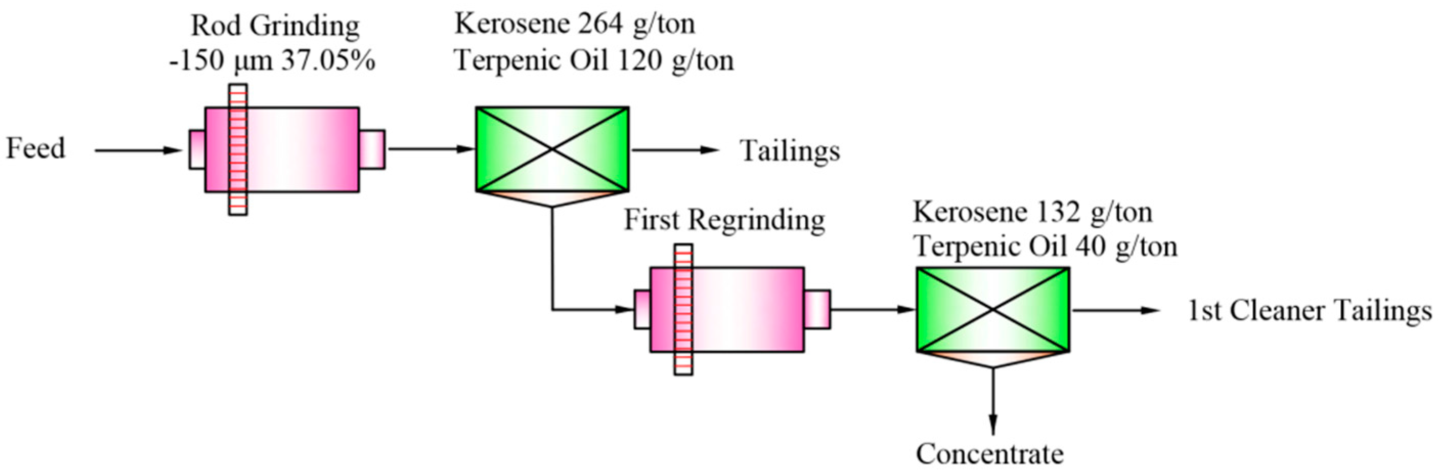
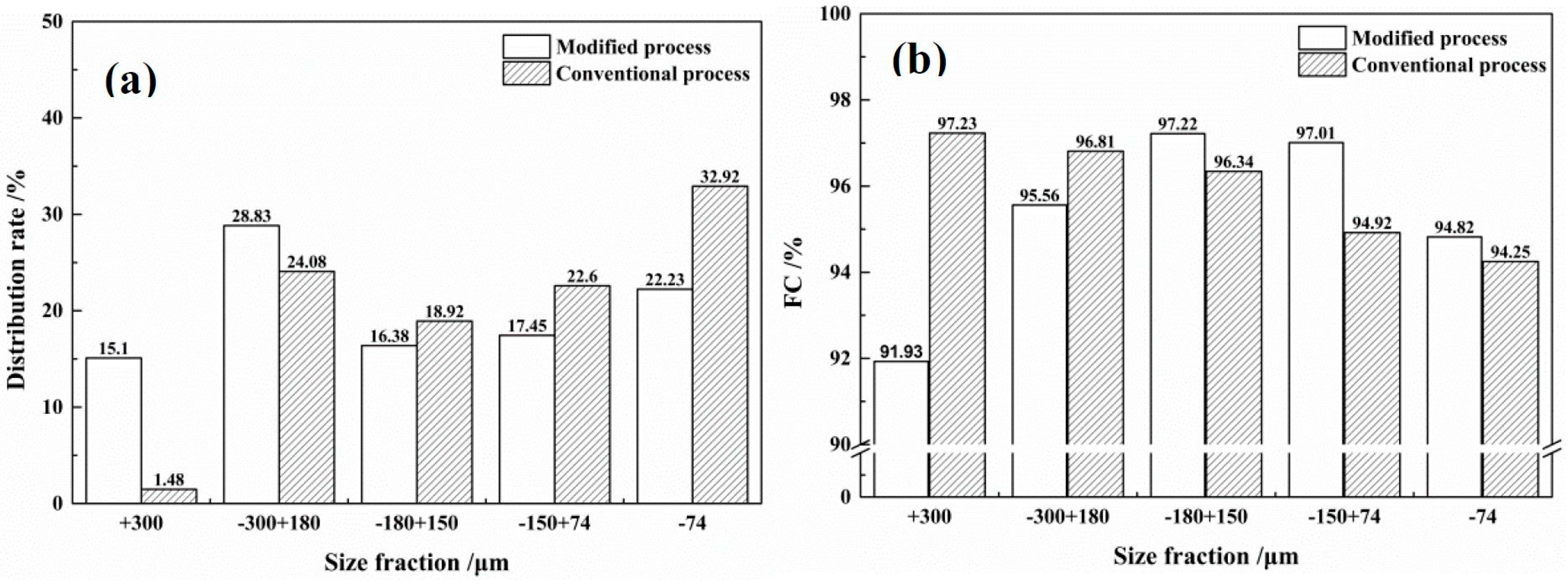
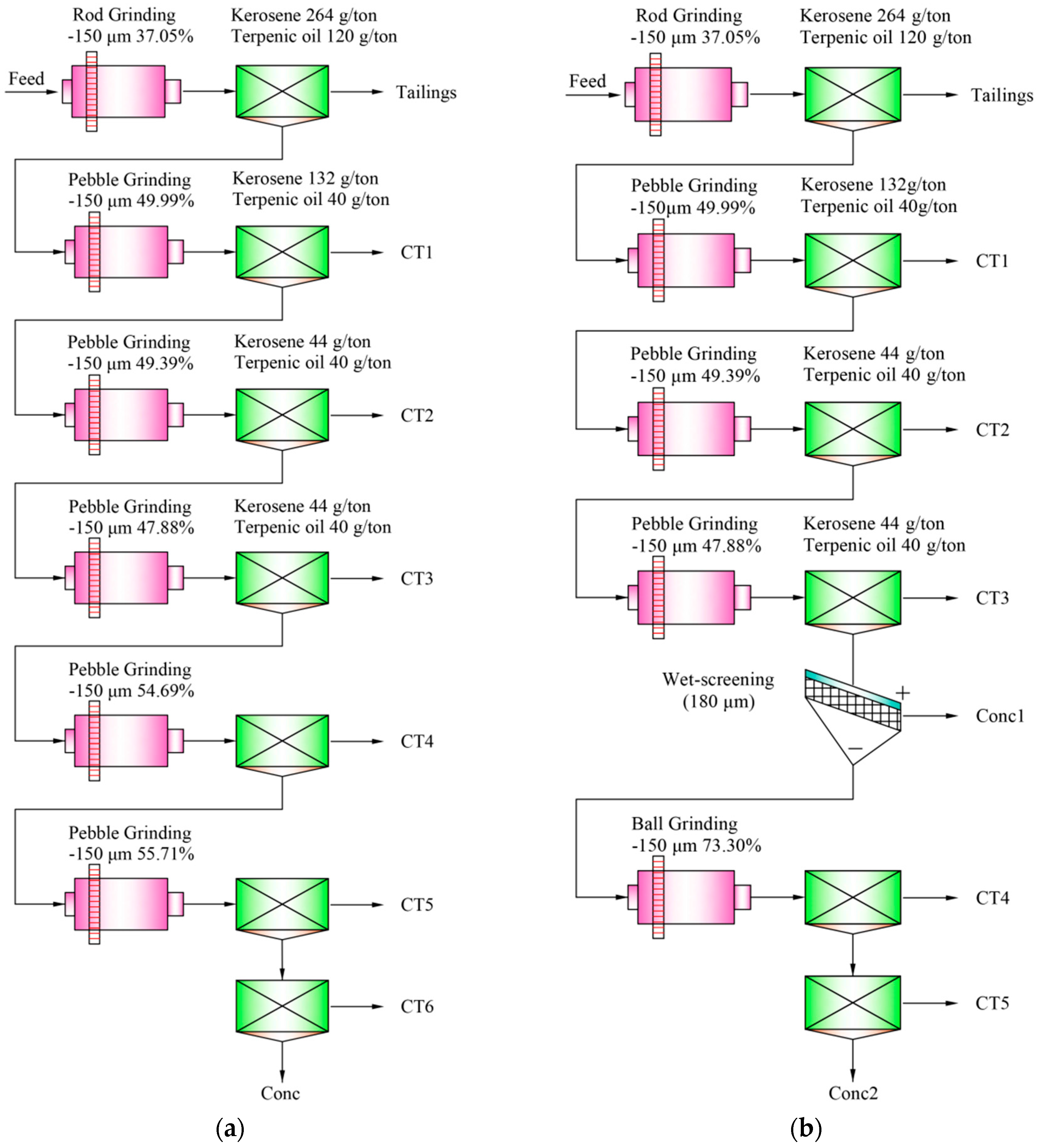
3.4. Open Circuit Tests

Based on the results of the experimental parameters tests, a series of open circuit tests of the raw ore were performed. Figure 7a shows one of the superior conventional open circuit test flowcharts of the raw ore, while Figure 7b presents a modified open circuit test flowchart, and the results of these two process are shown in Table 5.
In the conventional open circuit process, as shown in Figure 7a, the raw ore was subject to coarse rod grinding and rough flotation once each, with the rough concentrate then successively reground five times and refloated six times, with pebble as the only regrinding medium for all the regrinding process. Table 5 shows that the FC content and recovery of the final concentrate are 95.40% and 91.26%, respectively. The FC content of the final concentrate has a significant upgrade, and the recovery only slightly decreases by approximately 5% compared with the rough concentrate. Note that the cumulative recovery loss of all the middlings are low because of the either low FC content of the CT1–CT3 or the low yields of the CT4–CT6. It was not proposed to further treat the middlings, but discarding them as tailings, and consequently no close circuit was needed. Therefore, the flotation process was simplified and the stability of each product was maintained. Furthermore, the high recovery achieved through this open circuit test fully indicated that the beneficiability of this graphite ore was particularly excellent because most graphite ores worldwide, including many large flake-graphite ores, were not capable of achieving such a high recovery using the similar open circuit process parameters [34,35,36,37].
Separately considering the recovery and FC content of the final concentrate, this conventional open circuit process was desirable. However, the priority of this high-quality large-flake graphite ore was to prevent the large flakes from excessive grinding and simplify the process. Figure 7b shows a modified open circuit process, a pre-screening process was adopted after the third cleaning flotation operation, and steel balls were introduced to replace the pebble as the subsequent regrinding medium to improve the grinding efficiency and stability [38]. The efficiency of grinding depends on the surface area of the grinding medium. Since balls have a greater surface area per unit weight than rods, they are better suited for fine finishing [20,31,32]. As a result, one stage of grinding and flotation was removed and the process was shortened. After the pre-screening process, the +180 μm size fraction concentrate was separated from the process in advance and no longer reported to the subsequent grinding operation. Consequently, this part of product would significantly ensure the content of large flakes. The results of this modified process are also shown in Table 5. The comprehensive FC content and recovery of the final concentrate are basically identical between the modified process and the conventional one, whereas the size distribution of the concentrate and the FC content of the corresponding size fraction from these two open circuit process, as shown in Figure 8a,b, are significantly diversified.
In Figure 8b, the FC content of concentrate produced from the conventional open circuit shows a positive correlation with the size distribution. A larger size fraction corresponds to a higher FC content, which demonstrates that the large flakes were relatively purer than the small particles. However, this pattern is only applicable at the fine size fractions for the modified process. The quality of +300 μm and −300 + 180 μm size fractions are relatively inferior, and the FC content of these two size fractions are 91.93% and 95.56%, respectively. This is understandable because the +180 μm size fraction was pre-screened from the process and some gangue was not fully liberated with the concentrate.
However, the advantage of the modified process was obvious. Figure 8a shows that the total +150 μm size fraction, the large flake graphite, exceeds approximately 16% that of the conventional one. Note that the content of the +300 μm size fraction, at 15.10%, is more than ten times and the −300 + 180 μm size fraction, at 28.83%, is 4.75% higher than that of the previous process. This distinctive difference in size distribution indicates that this modified pre-screening process effectively preserved the large graphite flakes and is of great significance in improving the industrial value of this ore.
The flake shape and surface characteristics of the final concentrate were investigated using SEM analysis, and the SEM images of the +180 μm size fraction and −180 μm size fraction are shown in Figure 9. Most of the graphite flakes are perfectly crystallized and the flakes are intact and thick. Part gangue minerals, in Figure 9a, are observed and that is the reason for the relatively low FC content of the large-sized fraction. However, the surfaces of the fine flakes are cleaner and spotless.

4. Conclusions

In this work, a steel rod was applied as the coarse grinding medium to reduce the destruction of graphite flakes and improve the grinding efficiency, and a pebble mill was adopted for the regrinding process. The raw ore, coarse ground one time with rough flotation, then the rough concentrate was reground five times and refloated six times, achieved a final concentrate with 95.40% FC content and 91.26% recovery, whereas the +150 μm size fraction of the final concentrate was only 44.48%. Thus, a suitable approach of pre-screening the large-sized fraction of the concentrate was applied. After regrinding three times and refloating three times, the intermediate concentrate was wet-screened in advance, and the +180 μm concentrate was directly collected as one of the final concentrates. The other concentrate was obtained after the subsequent ball regrinding and twice-cleaner flotation. The recovery of the final concentrate was slightly upgraded to 92.35% at an FC content of 95.79%, and the content of +150 μm concentrate was significantly increased to 60.31%, which indicated that the modified pre-screening process efficiently preserved the large graphite flakes.

Acknowledgments

This research did not receive any specific grant from funding agencies in the public, commercial, or not-for-profit sectors.

Author Contributions

Kangkang Sun conceived and designed the experiments, performed the experiments, and wrote the paper under the supervision of Lingyan Zhang. Yangshuai Qiu revised the manuscripts and approved the manuscripts.

Conflicts of Interest

The authors declare no conflict of interest.

References

  1. Inagaki, M.; Masahiro, T.; Kang, F.Y.; Zheng, Y.P.; Shen, W.C. Pore structure of exfoliated graphite—A report on a joint research project under the scientific cooperation program between NSFC and JSPS. New Carbon Mater. 2003, 18, 241–249. [Google Scholar]
  2. Luke, L.; Chang, Y. Industrial Mineralogy: Materials, Processes, and Uses; Prentice Hall: Upper Saddle River, NJ, USA, 2002. [Google Scholar]
  3. Crossley, P. Graphite—High-tech supply sharpens up. Ind. Miner. 2000, 398, 31–47. [Google Scholar]
  4. Acharya, B.C.; Rao, D.S.; Prakash, S.; Reddy, P.S.R.; Biswal, S.K. Processing of low grade graphite ores of Orissa, India. Miner. Eng. 1996, 9, 1165–1169. [Google Scholar] [CrossRef]
  5. Mitchell, C.J. Industrial Minerals Laboratory Manual: Flake Graphite; British Geological Survey: Nottingham, UK, 1992. [Google Scholar]
  6. Chehreh Chelgani, S.; Rudolph, M.; Kratzsch, R.; Sandmann, D.; Gutzmer, J. A review of graphite beneficiation techniques. Miner. Process. Extr. Metall. Rev. 2016, 37, 58–68. [Google Scholar] [CrossRef]
  7. Qiu, Y.; Yu, Y.; Zhang, L.; Qian, Y.; Ouyang, Z. An Investigation of Reverse Flotation Separation of Sericite from Graphite by Using a Surfactant: MF. Minerals 2016, 6, 57. [Google Scholar] [CrossRef]
  8. Weng, X.; Li, H.; Song, S.; Liu, Y. Reducing the Entrainment of Gangue Fines in Low Grade Microcrystalline Graphite Ore Flotation Using Multi-Stage Grinding-Flotation Process. Minerals 2017, 7, 38. [Google Scholar] [CrossRef]
  9. Wakamatsu, T.; Numata, Y. Flotation of graphite. Miner. Eng. 1991, 4, 975–982. [Google Scholar] [CrossRef]
  10. Vasumathi, N.; Kumar, V.T.V.; Nayak, B.; Rao, S.S.; Prabhaker, S.; Raju, B.G. Beneficiation of low grade graphite ore of eastern India by two-stage grinding and flotation. J. Min. Metall. A Min. 2014, 50, 9–17. [Google Scholar] [CrossRef]
  11. Tamashausky, A.V. Graphite. Am. Ceram. Soc. Bull. 1998, 77, 102–104. [Google Scholar]
  12. Asbury Carbons. Natural Flake Graphite. Available online: http://asbury.com/technical-presentations-papers/materials-in-depth/natural-flake-graphite (accessed on 5 June 2017).
  13. Bhima, R.R.; Patnaik, N. Preparation of high pure graphite by alkali digestion method. Scand. J. Metall. 2004, 33, 257–260. [Google Scholar] [CrossRef]
  14. Lu, X.J.; Forssberg, E. Preparation of high-purity and low-sulphur graphite from Woxna fine graphite concentrate by alkali roasting. Miner. Eng. 2002, 15, 755–757. [Google Scholar] [CrossRef]
  15. Wissler, M. Graphite and carbon powders for electrochemical applications. J. Power Sources 2006, 156, 142–150. [Google Scholar] [CrossRef]
  16. Xie, Z. Study on protecting flaky graphite concentration. China Non-Met. Min. Ind. Her. 2005, 1, 010. [Google Scholar]
  17. Long, Y.; Zhang, G.W.; Li, Z.Q.; Xiao, X. Research progress of the protecting large glaky graphite. China Non-Met. Min. Ind. Her. 2013, 2, 016. [Google Scholar]
  18. Yue, C. Study on the damage of large-scale flaky graphite and new grinding-flotation process. Non-Met. Mines 2002, 25, 36–37. [Google Scholar]
  19. Chen, X.; Peng, Y. The effect of regrind mills on the separation of chalcopyrite from pyrite in cleaner flotation. Miner. Eng. 2015, 83, 33–43. [Google Scholar] [CrossRef]
  20. Wills, B.A.; Finch, J. Wills’ Mineral Processing Technology: An Introduction to the Practical Aspects of Ore Treatment and Mineral Recovery; Butterworth-Heinemann: Oxford, UK, 2015. [Google Scholar]
  21. Long, Y.; Zhang, G.W.; Xiao, X.; Li, Z.Q. Grinding of Flake Graphite with Vertical Agitating Mill. Min. Metall. Eng. 2014, 34, 41–44. (In Chinese) [Google Scholar]
  22. Yue, C. Research on speed flotation of flake graphite. Non-Met. Mines 2007, 5, 018. [Google Scholar]
  23. Newcombe, B. Predicting plant scale flash flotation performance—Validation of laboratory methodology and applications for use. Miner. Eng. 2014, 57, 57–67. [Google Scholar] [CrossRef]
  24. Newcombe, B.; Bradshaw, D.; Wightman, E. Flash flotation and the plight of the coarse particle. Miner. Eng. 2012, 34, 1–10. [Google Scholar] [CrossRef]
  25. Qu, X.; Zhang, L.; Li, Q. Study on new technology to protect flake graphite by grading for grinding and floating. Non-Met. Mines 2015, 38, 53–55. [Google Scholar]
  26. Newcombe, B.; Wightman, E.; Bradshaw, D. The role of a flash flotation circuit in an industrial refractory gold concentrator. Miner. Eng. 2013, 53, 57–73. [Google Scholar] [CrossRef]
  27. He, P.; Zhang, L.; Deng, C. Selective Grinding and Floating Test on Flakey Graphite in Africa. Bull. Chin. Ceram. Soc. 2016, 9, 2826–2831. [Google Scholar]
  28. Sabih, A.; Radziszewski, P.; Mullany, I. Investigating grinding media differences in microstructure, hardness, abrasion and fracture toughness. Miner. Eng. 2017, 103, 43–53. [Google Scholar] [CrossRef]
  29. Yu, X.B.; Fang, H.P.; Xiao, Y.J.; Zhang, L.Y. Experimental study on purification of a fine-scaled graphite ore by flotation. Conserv. Util. Miner. Resour. 2000, 1, 003. [Google Scholar]
  30. Xie, G.Y.; Zhang, M.X.; Bian, B.X.; Fang, M.Q. Mineral Processing; China University of Mining and Technology Press: Xuzhou, China, 2001. [Google Scholar]
  31. Duan, X.X. Crushing and Grinding; Metallurgical Industry Press: Beijing, China, 2006. [Google Scholar]
  32. Zhang, G.F.; Feng, Q.M.; Chen, Q.Y.; Zhang, P.M. Study on grinding media of selective grinding of bauxite. J. Cent. South Univ. Sci. Technol. 2004, 4, 552–556. [Google Scholar]
  33. Feng, Q. Study on wet grinding parameters for producing ultra-fine graphite particles. China Non-Met. Min. Ind. Her. 2003, 6, 005. [Google Scholar]
  34. Xie, C.; Yuan, H. Research on concentration of large flake graphite with the filling-type flotation machine. Met. Mine 2010, 7, 018. [Google Scholar]
  35. Ravichandran, V.; Eswaraiah, C.; Manisankar, P. Beneficiation of low grade graphite ore deposits of Tamilnadu (India). Ultra Chem. 2012, 8, 159–168. [Google Scholar]
  36. Sun, Z.; Jia, F.; Li, Q. Study on Beneficiation Process of a Low Grade Graphite Ore in Inner Mongolia. Ind. Miner. Process. 2012, 9, 003. [Google Scholar]
  37. Vasumathi, N.; Kumar, T.V.V.; Ratchambigai, S.; Rao, S.S.; Raju, G.B. Flotation studies on low grade graphite ore from eastern India. Int. J. Min. Sci. Technol. 2015, 25, 415–420. [Google Scholar] [CrossRef]
  38. Nkwanyana, S.; Loveday, B. Addition of pebbles to a ball-mill to improve grinding efficiency. Miner. Eng. 2017, 103, 72–77. [Google Scholar] [CrossRef]
Figure 1. XRD pattern of the raw ore.
Minerals 07 00115 g001
Figure 2. Optical microscope images of the raw ore: (a,b) polarizing microscope images 100×; (c,d) reflecting microscope images 50×.
Minerals 07 00115 g002
Figure 3. Flowchart of coarse grinding and rough flotation for experimental parameters.
Minerals 07 00115 g003
Figure 4. Experimental parameters of coarse grinding and rough flotation tests: (a) Grinding curves; (b) grinding media; (c) grinding fineness; (d) dosage of kerosene; (e) terpenic oil.
Minerals 07 00115 g004
Figure 5. Flow chart of flotation for the first regrinding experimental parameters.
Minerals 07 00115 g005
Figure 6. Experimental parameters of first regrinding tests: (a) First regrinding curves; (b) regrinding media; (c) regrinding fineness.
Minerals 07 00115 g006
Figure 7. Flowcharts of (a) the conventional open circuit and (b) the modified open circuit.
Minerals 07 00115 g007
Figure 8. The size distribution rate (a) and the corresponding FC content (b) of concentrate by conventional and modified open circuit process.
Minerals 07 00115 g008
Figure 9. The SEM images of the final concentrate: (a,b) +180 μm size fraction; (c,d) −180 μm size fraction.
Minerals 07 00115 g009
Table 1. Chemical compositions of the raw ore (wt %).
CompositionSiO2Al2O3Fe2O3SO3K2OTiO2P2O5BaOMgOCaO
Content/%60.9313.214.134.010.940.570.400.150.140.10
CompositionNa2OSrOCr2O3ZrO2CuOZnOY2O3LOIFC
Content/%0.090.0380.0350.0150.0130.0070.00215.227.59
Table 2. Mineral compositions of the raw ore (wt %).
SpeciesGraphiteQuartzKaoliniteMuscoviteFibroliteLimoniteEpidoteOthers
Content/%7502385322
Table 3. Parameters of the grinding media.
MediaVolume-Weight (g/cm3)Specification (mm)Mill Charge Volume (%)
Coarse GrindingRegrinding
Steel Ball4.5Φ10–25Φ5–1040
Steel Rod5.6Φ20 × 200Φ10 × 10050
Pebble1.6Φ10–30Φ5–1550
Table 4. Liberation characteristics of the graphite flakes.
Size Fraction/μmAccording to Particle NumberAccording to Distribution Rate
Particle Numbers/nParticle Pumber Percentage/%Cumulative Particle Number Percentage/%Distribution Rate/%Cumulative Distribution Rate/%
+830360.650.6513.1313.13
−830 + 600871.572.2215.8729.00
−600 + 5001152.074.2910.4939.49
−500 + 30066211.9316.2130.1969.68
−300 + 23065611.8228.0314.9684.64
−230 + 18070012.6140.647.9892.62
−180 + 1505149.2649.902.9395.55
−150 + 10697417.5567.452.7898.33
−106 + 7573813.2980.741.0599.38
−75 + 4566812.0392.780.4899.86
−454017.22100.000.14100.00
Total5551100.00 100.00
Table 5. Flotation results of the conventional and the modified open circuit tests.
ProductConventional Open CircuitModified Open Circuit
Yield/%FC/%Recovery/%Yield/%FC/%Recovery/%
Conc17.1195.4091.263.0394.7340.12
Conc23.8696.6352.23
CT15.123.792.616.050.400.34
CT22.240.360.112.861.040.42
CT31.141.990.300.943.190.42
CT40.775.770.600.2628.761.05
CT50.2813.640.520.1139.190.54
CT60.1248.180.79---
Tailings83.210.343.8082.890.424.87
Total100.007.44100.00100.007.15100.00

