Article

Modeling and Analyzing Air Supply Control to Optimize Thermal Pattern in Iron-Ore-Sintering Process

1
School of Minerals Processing & Bioengineering, Central South University, Changsha 410083, China
2
Zhongye Changtian International Engineering Co., Ltd., Changsha 410021, China
3
Xiangtan Iron & Steel Co., Ltd. of Hunan Valin, Xiangtan 411101, China
*
Author to whom correspondence should be addressed.
Minerals 2025, 15(8), 770; https://doi.org/10.3390/min15080770
Submission received: 7 June 2025 / Revised: 14 July 2025 / Accepted: 18 July 2025 / Published: 22 July 2025
(This article belongs to the Section Mineral Processing and Extractive Metallurgy)

Abstract

This research proposes optimizing the thermal pattern in the sintering bed by manipulating the air supply. The impact of the air supply on the distribution of heat in the upper and lower layers of the material bed is investigated based on a numerical simulation model. An optimized air supply scheme is proposed to enhance the thermal distribution of the sintering bed. The simulation results suggest that decreasing the air supply during sintering in the upper layer leads to an increase in bed temperature and an extension of the melting zone thickness from 5 mm to 16 mm. Similarly, reducing the air supply during sintering of the lower layer prevents over-melting of the sintering material by reducing heat accumulation. However, both decrease the speed of vertical sintering. To optimize the sintering process, it is suggested to decrease the air supply during the early and late stages and increase it during the middle stage. This optimized air supply leads to a uniform temperature distribution, with a 30 °C decrease in the gap between the highest temperatures. Additionally, the melting zone thickness in the early sintering stage increases from 0 mm to 14 mm, and the average vertical sintering speed remains comparable.

1. Introduction

The iron-ore-sintering process is a crucial step in the production of iron and steel. However, it is also a major contributor to energy consumption, accounting for approximately 10% of the total energy used, and CO2 emissions, which make up nearly 15% of the total. The primary culprits responsible for this are coke breeze and anthracite, which are the most used solid fuels in the sintering process, and account for over 80% of the total energy consumption [1]. Unfortunately, their combustion reaction is the main source of gaseous pollutants such as COx and NOx. To promote the low-carbon, green, and high-quality development of the iron and steel industry, it is imperative to reduce fuel consumption. This is a critical issue that iron and steel enterprises must face head-on.
In the sintering process, there is heat accumulation inside the material bed. The ambient air is heated when passing through the upper material bed with high temperature, and the heat is transferred to the cold state material at the lower part of bed. Thus, the material near the bottom bed accumulates more heat. This uneven distribution of heat adversely affects the sinter yield and quality indices, and greatly reduces fuel utilization efficiency. Especially with the application of ultra-high bed sintering technology in recent years, the uneven heat distribution and the adverse effects it causes have become more significant [2]. It is the main technical means to improve the heat accumulation phenomenon and reduce the solid fuel by the refined operation methods such as fuel distribution and air volume distribution control; alternatively, new technologies such as hot-air sintering and hydrogen fuel injection have been considered.
The stratified distribution of solid fuel is an effective means to avoid the uneven heat pattern in the sintering bed. Z. Huang [3] proposed the concept of available heat accumulation and the calculation model of reasonable fuel distribution based on the material and heat balance calculation. The calculated results were verified using a sintering pot test, in which the fuel consumption was reduced by 3.69 kg/t, while the sinter quality was kept intact. Considering the effect of gas–solid heat transfer on available heat accumulation, X. Fan et al. [4] established a fuel distribution optimization model based on numerical simulation. With the controlling objective of proper temperature, X. Zhang et al. [5,6] proposed a reasonable fuel distribution scheme based on depth cells and analyzed the effect of fuel distribution with a comprehensive evaluation index of the sintering process. S. Shrestha et al. [7] investigated the state parameters of fuel distribution sintering via the numerical simulation model, and the influence of the air flow rate and bed height on the state parameters was discussed by the sensitivity analysis method. Although beneficial for balancing the heat distribution of the layer and reducing fuel usage, fuel segregation distribution is rarely implemented in industry because it is difficult to achieve ideal fuel distribution through fabric operation control alone. Although it is beneficial to equilibrate heat distribution and reduce fuel consumption, fuel segregation control is rarely applied in practical production because the ideal fuel distribution is difficult to realize by discharge operations.
External heat supplementation is also an important means to equalize the heat distribution of sintering bed. New sintering techniques such as gas fuel injection and flue gas circulation can provide additional heat from the upper layer. Gas jet sintering technology involves injecting hydrogen rich gas such as natural gas and coke oven gas into the surface after the material bed is ignited so that it can be burned in the upper part of the high temperate zone. This technology can effectively replenish the insufficient heat in the upper layer, improve the quality index of sinter and reduce solid fuel consumption [8,9]. Surface injection of natural gas in the sintering process was first proposed by JFE [10] in 2009 and has been applied in the industry. Z. Chen et al. [11] found out that gas fuel injection has a positive effect on improving the thermal state and sinter strength, but the increase in the injection ratio has a negative effect instead. Researchers [12] also used a numerical simulation model to analyze the effect of gas fuel injection on the MQI of the upper layer. Flue gas recycling sintering involves returning part of the exhaust gas generated in the sintering process to the sintering bed [13] with the aim of making full use of the sensible and CO chemical heat and reducing the emission of pollutants. X. Fan et al. [14] investigated the effect of gas composition and temperature on the sintering process and found that the sensible heat of circulating flue gas can raise the temperature of the upper layer and decrease the cooling rate, thus significantly promoting the yield and tumbler index of sinter. However, when the flue gas temperature is too high, the gas expansion will lead to a reduction in gas flow and a slowdown in fuel combustion rate, which deteriorates the yield and quality indices. G. Wang et al. [15,16] demonstrated that flue gas circulation sintering has a positive effect on improving the uneven heat distribution via numerical simulation experiments, but it also has a negative effect on the combustion front rate.
Air is an important medium for heat exchange in the sintering process, and its flow rate has a significant effect on the thermal state of the sintering bed. Researchers [17] developed the air flow distribution model of sintering and analyzed the influence of the proportion and particle size of fuel, pallet speed and material bed height on the surface air supply rate, as well as the corresponding appropriate air supply rate adjustment measures to ensure the combustion front speed. X. Zhang et al. [18] measured the air flow distribution on the sintering bed surface and proposed a method to transfer the effective air volume from the head and tail sections to the middle parts of the sintering machine, and a reasonable distribution scheme of the air flow alongside the moving direction of the sintering machine. J. Zhou et al. [19] conducted an experiment to change the air flow by controlling the negative pressure of the sintering pot, and the results showed that the yield index, utilization coefficient and vertical sintering speed could be improved by decreasing the negative pressure or air flow at the early and late stages of sintering. The initial purpose of air flow distribution control was to reduce air leakage at the head and tail of the sintering machine, but, at the same time, to equalize the heat distribution, which has a positive effect on the sinter quality index. However, the function mechanism of the air flow on the sintering process and the influence law on the yield and quality index are still not clear, and manipulation is still mainly dependent on the testing and debugging in the production field.
To achieve an optimal thermal state distribution during the sintering process, it is crucial to reasonably and accurately regulate the air supply rate. To accomplish this, a gas flow resistance model is established based on the unique characteristics of the sintering bed structure. The impact of air supply on the heat distribution in both the upper and lower layers of the sintering bed is thoroughly investigated using a modified mathematical model. Finally, the air supply of each section along the sintering machine is optimized to achieve a uniform thermal pattern, and a comprehensive control scheme is proposed. The optimized air supply control scheme has been shown to promote the uniform distribution of heat in the material layer, with the temperature gap in the maximum temperature of the layer reduced by 30 °C. In addition, it has been demonstrated that the scheme maintains the vertical sintering speed and avoids the unfavorable effect on the production efficiency. These findings provide an important reference for on-site production operation.

2. Materials and Methods

2.1. Description of Sintering Process

A typical sintering process can be described as in Figure 1. Following the mixing and granulation, the raw mixture is discharged onto the sintering pallets, and the solid fuel in the surface layer is ignited as it passes through the ignition hood. With the powerful suction of the main exhaust fan, a vacuum is created inside the wind-boxes, and a copious amount of air is drawn into the sintering bed from above. The convection heat transfer causes the solid fuel in the lower layer to combust, and the sinter finally takes shape after melting and condensation.
The illustration reveals the intricate process of air being injected into the sintering bed and transforming into flue gas before streaming into the wind-boxes. The flue gas is then directed into the flue collector and expelled. Typically, the wind-boxes maintain a uniform negative pressure of approximately 10~16 kPa during normal operation. However, due to the uneven gas flow resistance from the loading end to the discharging end, the air flow rate on the bed surface fluctuates.
The thermal state and partition within the sintering bed is depicted in Figure 1b. The melting zone is defined as the area in which the material undergoes phase transformation, characterized by softening, melting, and the formation of a liquid phase, with a solid phase temperature that exceeds 1200 °C delineating the boundary. The reaction zone, on the other hand, pertains to the domain in which chemical reactions, such as fuel combustion and carbonate decomposition, occur. This zone is categorized based on temperatures ranging from 700 to 1200 °C. The drying and preheating zone refers to the region where materials are heated by the hot exhaust gas. The boundary of this zone is set at 100–700 °C.
The thickness of the high-temperature zone (including the melting zone and reaction zone) in the upper layer is thin after ignition and heat preservation. If the gas flow rate is too high, the gas–solid convective heat exchange is intensified, and the development of the maximum temperature and melting zone thickness is restricted, which is unfavorable for the mixed material to melt into the sinter. During the middle stage, the high temperature zone widens, the gas is expanded by heat and the flow resistance increases. The lack of gas flow will make the heat transfer rate and combustion rate decrease, which has a negative impact on the yield and quality indices. At the late stage, the heat in the lower part of the sintering bed accumulates, and excessive gas flow will further aggravate heat accumulation. The sintering materials will be excessively melted due to the high temperature, which will lead to the deterioration of sinter quality. Therefore, meticulous operation of the air supply can effectively change the non-uniform heat distribution, which is conducive to improving the sinter yield and quality indices and reducing energy consumption.

2.2. Numerical Simulation Model of Sintering

Considering sintering as a one-dimensional unsteady process, based on the porous medium theory and non-thermodynamic equilibrium theories [4,6], the energy and component conservation equations for solid phases (as illustrated in Equations (1) and (2)), and the energy, component, and mass conservation equations for gas phases (as illustrated in Equations (3)–(5)) are established in accordance with the characteristics of the sintering bed.
For the solid phase:
1     ε ρ s C p , s T s t   =   x 1     ε λ s T s x   +   h c A s T g     T s   +   k = 1 n φ k R k H k
1 ε ρ s y j t = k = 1 n j R j , k
For the gas phase:
ε ρ g C p , g T g t + u g ρ g C p , g T g x = x ε λ g T g x + h c A s T s T g + k = 1 n 1 φ k R k H k
ε ρ g y i t + ε u g ρ g y i x = k = 1 n i R i , k
ε ρ g t + ε u g ρ g x = i R i , k
where ε is the porosity of mixture bed, %; ρ is the density, kg/m3; u is the flow velocity, m/s; C p is the specific heat, J/(kg·K); T refers to temperature, K; t is time/s; λ is conductivity, W/(m·K); h c is convection heat transfer coefficient, W/(m2·K); A s refers to specific surface area, m2/m3; φ refers to the fraction of heat absorbed by solid; R is the reaction rate, kg/(m3·s); ∆H is the enthalpy of reaction, J/kg; and y is the mass fraction of solid and gas phases. Subscripts: s refers to the solid phase, g refers to gas phase, k is the index of reactions, and j is the index of solid and gas phases.
The reaction kinetics models mainly include fuel combustion (as shown in Equations (6)–(8)), carbonate decomposition (as depicted in Equation (9)), and water evaporation and condensation (as expressed in Equation (10)). These were established based on the chemical reaction behavior inside the sintering bed [4,6,20].
R f c = i = 1 m α i · R n u , i + 1 α i · R a d , i
R n u , i = 2 M c A s , n u , i C O 2 1 / k r , i + 1 / k a s h , i + 1 / k a l , i + 1 / k g b l , n u , i
R a d , i = 2 M c A s , a d , i C O 2 1 / k r , i + 1 / k a s h , i + 1 / k g b l , n u , i
R c d = M · A s · C c o 2 * C C O 2 ς d p S h · D C O 2 + 2 δ r 0 ε 1.41 D C O 2 r c + r 0 2 · D C O 2 * r c 2 · k i
R w d = γ · M H 2 O · A s · k H 2 O · P H 2 O * P H 2 O R g T g , P H 2 O * > P H 2 O R w c = M H 2 O · A s · k H 2 O · P H 2 O P H 2 O * R g T g , P H 2 O > P H 2 O *
where R f c is the reaction rate of the fuel particles, kg/(m3·s); R n u , i and R a d , i denote the combustion rate of fuel particles as nuclear particles and adhesive powders, respectively; α i is the partition coefficient introduced to express the proportion of nuclear particles and adhesive powder; M is the molecular weight, kg/mol; C refers to the molar concentration of the gas phase, mol/m3; k r , k a s h , k a l and k g b l denote the reaction rate constant of combustion reaction, ash layer, adhering layer, and boundary layer of gas phase, respectively, m/s; d p is the equivalent diameter of carbonate, m; S h is the Sherwood number; D C O 2   is the mass diffusion coefficient of carbon dioxide, m2/s; r 0 and r c refer to the initial radius and current radius of carbonate, m; and P H 2 O   is the partial pressure of water vapor, Pa.
This research focuses on the influence of the air supply rate. As the momentum equation of the gas phase significantly influences the accuracy of the simulation results, the flow resistance model of the gas phase in the sintering bed should be modified. Currently, the Ergun equation [21] is a commonly used empirical equation to describe the gas flow characteristics in the sintering bed, as shown in Equation (11).
Δ P h = k 1 · 1 ε 2 d p 2 · ε 3 · μ · u g + k 2 · 1 ε d p · ε 3 · ρ g · u g 2
where Δ P is the total pressure drop, Pa; h is bed height, m; d p is the particle size of the mixture, m; μ is the dynamic viscosity coefficient of gas, kg/(m·s); and k 1 and k 2 are viscous resistance and inertial resistance coefficient, respectively.
In most of the reported studies [15], the resistance coefficient mainly used k 1 = 150 and k 2 = 1.75 fitted by Ergun et al. through experimental data. For the sintering mixture bed, Hinkley et al. [22] modified k 1 = 323 and k 2 = 3.78 by fitting a large amount of experimental data. This corrected coefficient is only suitable for the raw mixture bed, and it is no longer applicable when the mixture is ignited and different zones with very different properties are formed from the top to the bottom, as shown in Figure 1b. J. Shibata et al. [23] obtained the resistance coefficients k 1 , j and k 2 , j for the mixture zone, condensing zone, drying zone, reaction zone, melting zone and sinter zone via layering experiments. The setting of this resistance coefficient is more consistent with the actual sintering process, but the experimental conditions such as raw material structure and bed height at that time were significantly different from those at present; thus, the fitting coefficient is no longer suitable for application.
In this study, the temperature, pressure, and gas flow rate of the sintering pot test were collected to establish the relationships between the inlet air flow rate and the outlet pressure drop of the sintering bed at different moments containing the unknown parameter k 1 and k 2 , as illustrated in Equations (12)–(14).
Δ P = i = 1 5 h i K 1 , i · μ · u g + K 2 , i · ρ g · u g 2
K 1 = k 1 d p 2 · 1 ε 2 ε 3
K 2 = k 2 d p · 1 ε ε 3
where i = 1, 2, ⋯, 5 denotes the five zones inside the sintering bed; and h is the thickness of each zone, m. The reaction zones are divided according to the solid phase temperature obtained in each iteration. To minimize the deviations between the calculated and measured values of total pressure drop, an iterative solution is conducted for k 1 and k 2 . The values k 1 and k 2 of each zone are listed in Table 1.

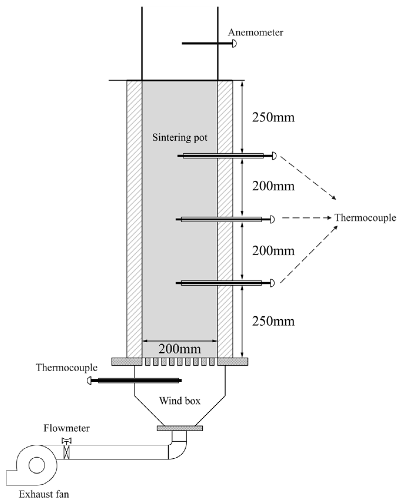
2.3. Experimental Setup

The influence of air supply rate on the thermal pattern of the upper and lower layers inside sintering bed was investigated via numerical simulation cases to identify the air supply distribution scenario that can optimize the non-uniform thermal profile in this research. A sintering pot test apparatus was employed to collect the required data for modeling and to verify the accuracy of the numerical simulation model, and the configuration of the test apparatus is depicted in Figure 2.

3. Results

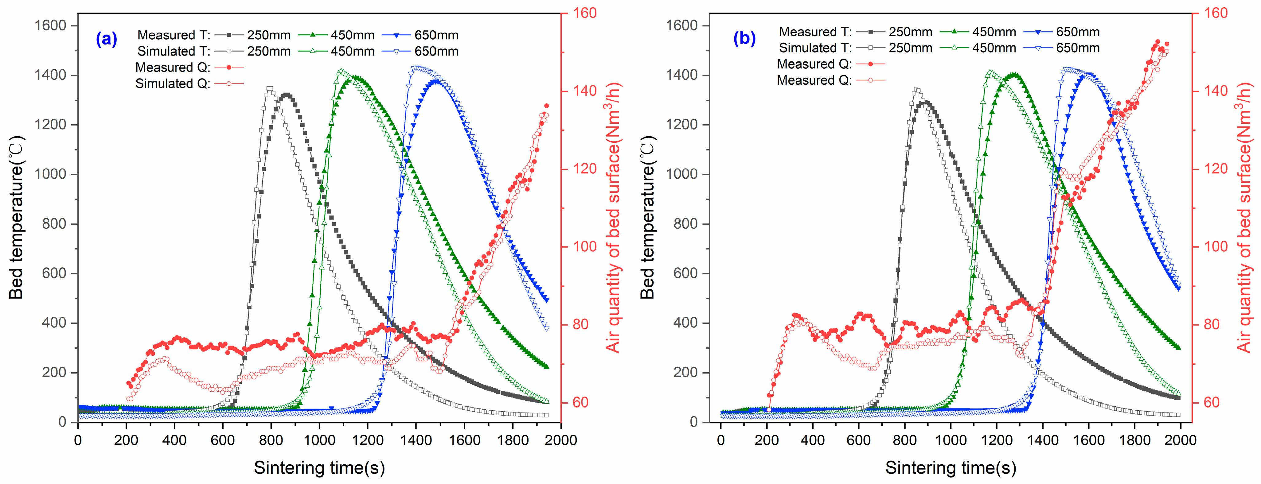
3.1. Model Validation

Two sets of experimental results with different negative pressures are used to verify the accuracy of the numerical simulation model, and the calculated values of the bed temperature (T) and air quantity of bed surface (Q) are compared with the experimental measured values. The initial and boundary conditions settings for the simulation experiments were obtained from experimental data, as listed in Table 2 and Table 3. A comparison of the results is demonstrated in Figure 3, where the height refers to the distance from the top of the sintering pot.
As can be seen from the figure, the maximum temperature tends to gradually increase due to heat accumulation, and the holding time of high temperature (>1200 °C) also expands. The maximum temperature gap between the two measurement points (250 mm and 650 mm) reached 108 °C, and the interval of high temperature holding time was 100 s when the sintering negative pressure was 12 kPa. The simulation results of the material temperature are in good agreement with the experimental detection results, the curves of the heating and cooling processes are basically the same, and the relative error between the calculated maximum temperature and the detected one is of less than 4%. For different pressure conditions, the air supply at the bed surface tends to rise after ignition and heat preservation, and then decreases to a certain degree, and remains stable in general until a significant increase occurs at a later stage. The simulated values are comparable to the trend of the measured results; due to the non-uniform characteristics of the actual system, the measured values have more obvious fluctuations. For sintering pressures of −10 kPa and −12 kPa, the average absolute errors between the simulated and measured values are ±5.4 Nm3·h−1 and ±4.6 Nm3·h−1, respectively.

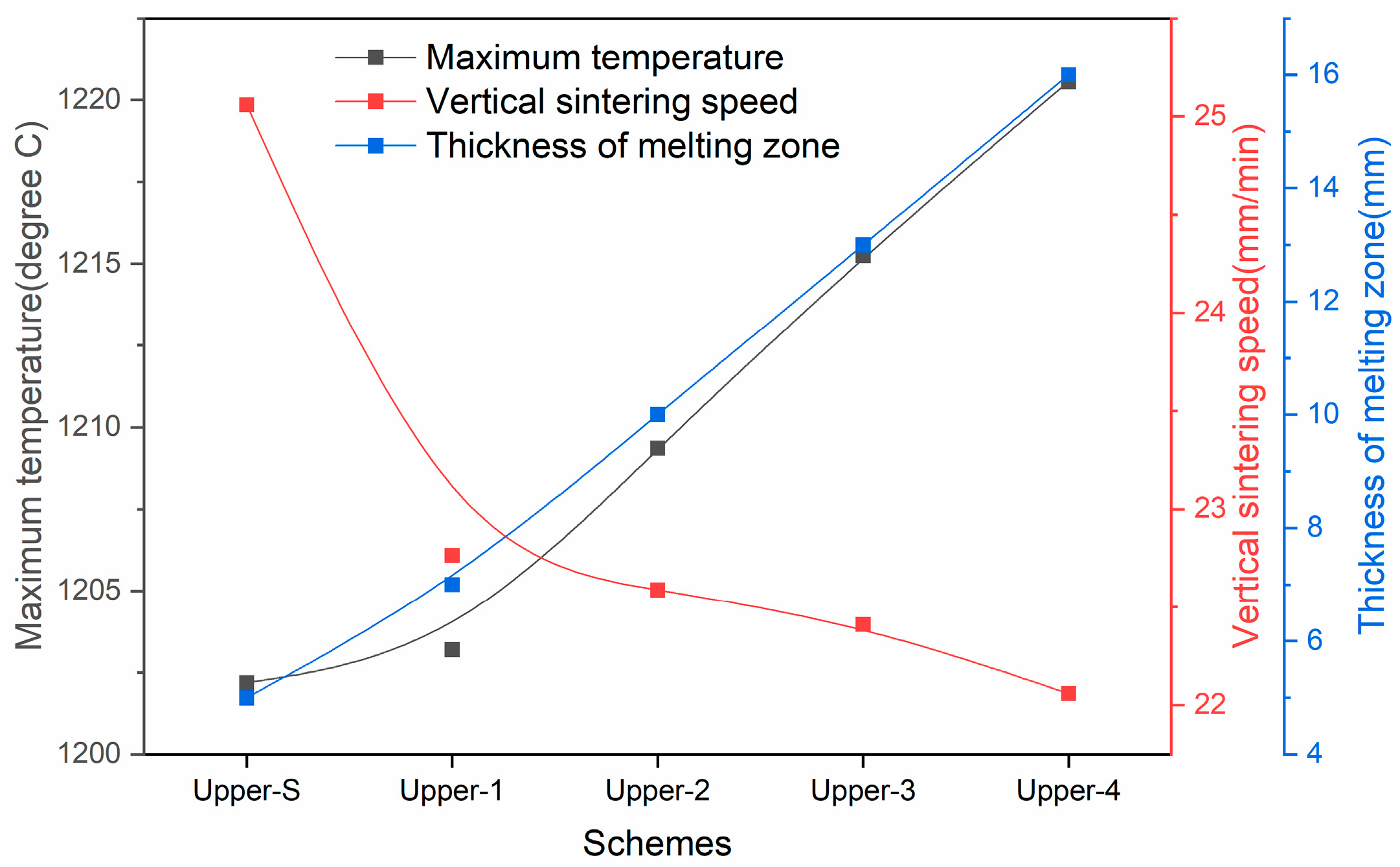
3.2. Effect of Air Supply on the Thermal State of Upper Layer

In a conventional sintering process, the negative pressure in the ignition stage is generally set at −6 to −5 kPa, or even around −3 to 0 kPa, to guarantee the ignition strength on the bed surface, and immediately turned on to −12 to −10 kPa (sintering pressure) after ignition. The higher exhaust pressure will inevitably cause a rapid increase in air flow on the bed surface. At this time, the maximum temperature of the upper layer is relatively low, and it has not caught up with the melting temperature. It will accelerate the cooling speed of the high-temperature zone while the air flow is high, and not facilitate the formation of the bonding phase, which is demonstrated in a lower yield and tumbler index of the upper layer sinter [24]. A series of simulation schemes were designed to analyze the effect of reducing the inlet air flow on the thermal state of the sintering bed after the ignition and heat preservation, as listed in Table 4. The inlet air supply is mainly controlled by the negative pressure at the bottom of the sintering bed. Taking the −12 kPa sintering scheme as the benchmark, four sets of simulated experimental schemes with gradient increase in negative pressure are designed, which resulted in different reductions in air supply on the bed surface. The thermal states after the air supply control are compared, as illustrated in Figure 4.
As the air supply decreases, the maximum temperature tends to increase continuously, while the thickness of melting zone increases from 5 mm to 16 mm. Due to the decrease in the gas velocity in the sintering bed, the convective heat exchange intensity between the gas and solid phase decreases, and the cooling rate of the sinter and the melting phase in the upper layer slow down. The gain maximum temperature is conducive to the formation of a liquid phase to bind more materials. Meanwhile, the decrease in cooling speed is favorable for sufficient condensation and crystallization of the liquid phase. That favors the stabilization of the yield and tumbler index. However, as the air supply decreases, the gas diffusion in the reaction zone is hindered, which impedes the combustion reaction. The vertical sintering speed, defined as the downward progression of the 1200 °C isotherm, is reduced from 17.01 mm·min−1 to 14.64 mm·min−1, which potentially maintains a negative effect on the yield index. In conclusion, the air supply distribution pattern of the Upper-3 scheme can improve the maximum temperature and melt zone thickness in the upper layer while maintaining a certain vertical sintering speed, which is convenient for improving the yield and quality indices.

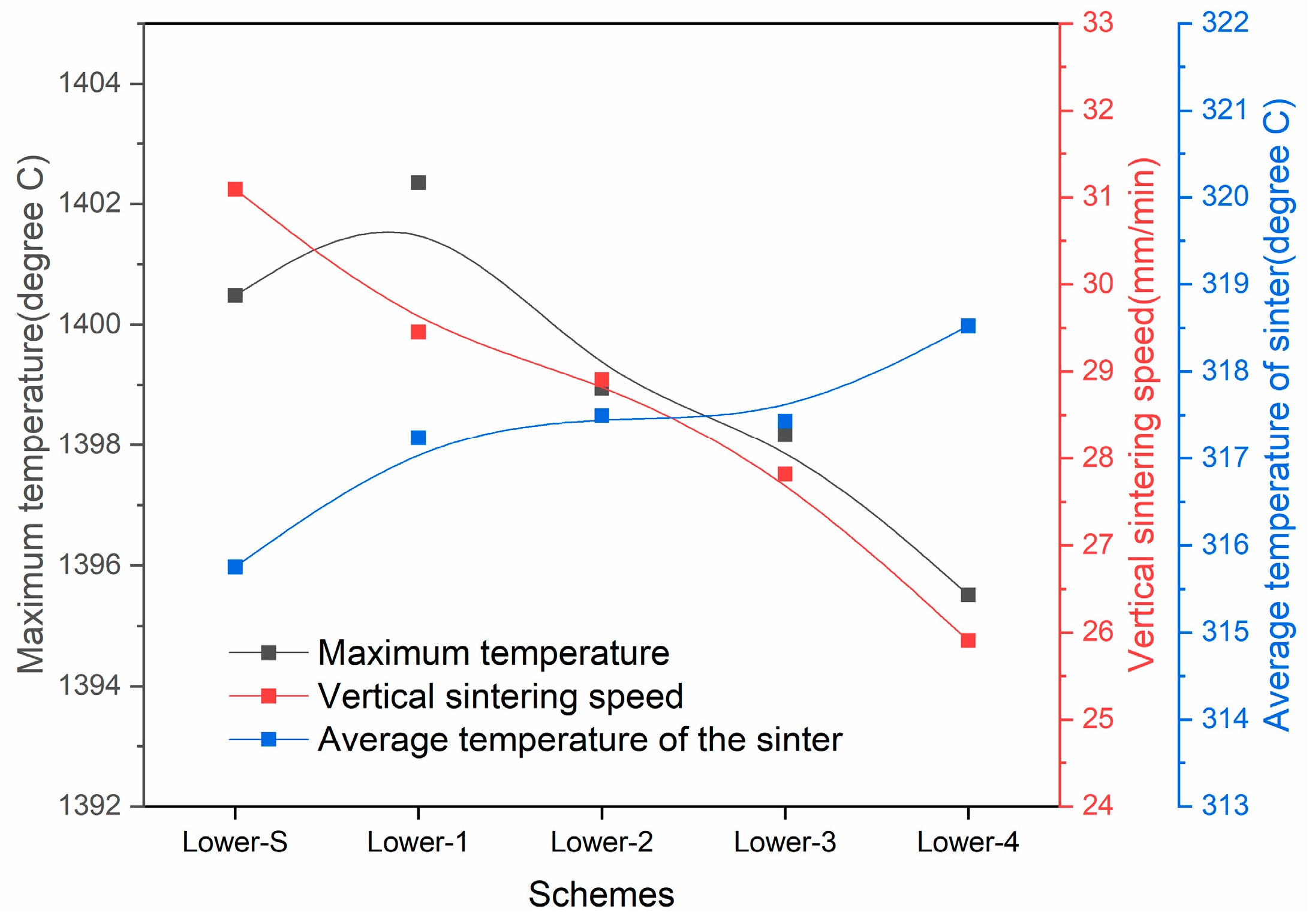
3.3. Effect of Air Supply on the Thermal State of the Lower Layer

At the later stage of sintering, the sinter zone with less gas flow resistance occupies a higher percentage in whole sintering bed, while the drying and preheating zone with the greatest gas flow resistance disappears so that the air supply increases rapidly if a certain sintering pressure is maintained. Because of the heat accumulation effect, the increase in air supply accelerates the cooling of the sinter, and the heat is concentrated in the lower layer, which makes the maximum temperature increase continuously. The excessive temperature possibly induces over-melting of the lower layer, which favors the formation of sinter with large holes and thin walls that has poor strength and reduction performance [25]. Therefore, the effect of the inlet air supply controlled on the thermal state at the late stage of sintering were investigated, and the simulation schemes are listed in Table 5. The finish sintering time at a constant negative pressure (−12 kPa) is 32 min; so, the period from 28 to 32 min is divided into four stages with the sintering negative pressure reduced to −6 kPa, −4 kPa, etc., subject to the other boundary conditions being consistent. The maximum temperature of the sintering bed, the vertical sintering speed, and the sinter temperature of the upper layer after 32 min are compared, and the results are shown in Figure 5.
As shown in the figure, reducing the negative pressure at the later stage of sintering to decrease the sintering air supply can make the maximum temperature of the lower layer drop, while the average temperature of the sinter in the upper layer rises. The simulation results indicate that the gas–solid convective heat exchange in the material layer is decelerated with the reduction in air supply, and the heat accumulation effect is diminished, which can prevent over-melting of the sintering molten in lower layer. However, the reduction in negative pressure has a greater effect on the vertical sintering speed. The vertical sintering speed drops to a minimum of 23.66 mm·min−1 with the gradient distribution of pressure in comparison with 28.39 mm·min−1 when the negative pressure is normally −12 kPa. Above all, the air supply distribution of the Lower-3 scheme is preferable. The maximum temperature of the lower layer tends to decrease, and the average temperature of the upper sinter rises while preventing a significant decrease in the vertical sintering speed.

3.4. Optimization of Air Supply Distribution

At the early stage of sintering, the high-temperature zone of the upper layer is relatively thin. Decreasing the negative exhaust pressure of front wind-boxes and scaling down the air supply can increase the maximum temperature and thickness of the melting zone, which is advantageous to improving sinter quality. At the later stage, the sintering progress is basically completed and the air supply required for heat transfer is diminished, and it is possible to decrease the negative pressure of exhaust air in the tail wind-boxes. The decreasing negative pressure of the exhaust air in the front and tail wind-boxes also slows down the vertical sintering speed, which has a negative impact on the sinter output. Therefore, it is necessary to increase the sintering air supply by increasing the negative pressure of the middle wind-boxes and thus boosting the vertical sintering speed of the corresponding sintering bed in the middle area to compensate for the negative effect of the slowed-down vertical sintering speed in the front and tail areas. The inlet air supply at the bed surface of the optimization scheme and reference scheme are presented in Figure 6. The effect of the air supply distribution on the thermal state of the material layer is demonstrated in Figure 7.
It is observed from the figure that the decreasing air supply at the early stage adversely affects the vertical sintering speed while improving the thermal state of the upper layer. With the increase in air supply at the middle stage, the variations in the maximum temperature and the thickness of the melting zone are minor. The gradient reduction in the air supply at the later stage has a minor effect on the maximum temperature and the thickness of the melting zone. Taking the optimized air supply distribution scheme, the temperature profile is more homogeneous, and the deviation of the highest temperature decreases by 30 °C. The average thickness of the melting zone is equivalent, but the thickness in upper layer increases from 0 mm to 14 mm.

4. Discussion

According to the gas flow resistance characteristics of each zone in the sintering bed, a simulation model of the flow field was developed by using the computational fluid dynamics method and the sintering chemical reaction model. A comparison of the simulation results with the measured results shows that the relative error of the maximum temperature is of less than 4%, and the average error in surface air quantity is within ±5.4 Nm3·h−1. It shows that the model can not only accurately simulate the temperature field of the material bed but also calculate the change in the air supply on the surface, which has not been carried out in past research. Using the model to analyze the impact of air supply on the thermal pattern of upper and lower layers shows that reducing air volume during upper-layer sintering increased the bed temperature and increased the melting zone thickness from 5 mm to 16 mm, improving the upper layer’s sintering yield and drum strength but lowering the vertical sintering speed by 3 mm/min. During lower-layer sintering, air supply reduction reduces the role of the heat storage, and prevents over-melting of the lower layer while also decreasing the vertical speed by 1.64 mm/min. Reducing the air flow improves the temperature distribution of the material layer, which is conducive to improving the yield and drum strength of the sintered ore, but, at the same time, significantly reduces the vertical sintering speed, resulting in the negative impact of the sintered ore production reduction. For this reason, the air supply in the middle phase of sintering can be increased. The simulation results of the optimization scheme show that the difference in the highest temperature of the material layer decreased by 30 °C, and the average vertical sintering speed only slightly decreased from 23.27 mm/min to 22.88 mm/min, avoiding the impact on the sintered ore yield.
Air supply control has proven effective in promoting uniform heat distribution within the sintering bed. Although its impact is not as significant as that of newer techniques such as fuel layer charging or surface injection of hydrogen-enriched gas, the proposed technology offers advantages in terms of relative ease of implementation in industrial settings and broad applicability. Moreover, air supply control holds high potential for coupling with these newer process technologies, representing a crucial technical pathway for the realization of low-carbon sintering.
In subsequent research, more in-depth breakthroughs on the basis of the existing research are expected. Firstly, the current one-dimensional non-equilibrium model will be upgraded to a two-dimensional/three-dimensional model, which will provide a powerful tool in the visualization of heat distribution in the sintering bed. Then, in-depth investigation of fuel particle size and fuel distribution in the material layer will be carried out to further improve the uniformity of heat distribution in the sintered material layer by optimizing the composition and distribution of fuel particle size and more accurately controlling the temperature field in the sintering process. Finally, in-depth research will be carried out on the design of exhaust flue and valve regulation and control of sintering equipment through the reasonable adjustment of parameters such as the diameter, length and direction of the flue pipe, as well as the intelligent and real-time control of the opening of the valve, in order to further balance the effect of air extraction and the thermal state of the material layer in the process of sintering and ultimately transform. These research results will eventually be transformed into practical and effective guidance suggestions for actual sintering production, which will allow the sintering process to move forward in the direction of intelligence, efficiency and high quality.

5. Conclusions

This study investigates the impact of air supply on the thermal state in mixed-material sintering beds, concentrating on non-uniform heat distribution and insufficient fuel utilization of the sintering process. This study establishes a modified gas momentum equation and a new numerical simulation model for the sintering process, verifying its accuracy through sintering pot tests. This study also investigates the effect of air supply on the thermal state of the upper and lower material layers. Reducing air supply during upper-layer sintering increases the sintering temperature, melting zone thickness, and sinter yield and tumbler index. Reducing air supply during lower-layer sintering weakens the heat storage effect, preventing over-melting but decreasing the vertical sintering speed. An air supply optimization scheme is proposed to reduce air supply at the early and late stages and increase it at the middle stage, resulting in a more homogeneous temperature profile.

Author Contributions

Conceptualization, X.H. and X.F.; Data Curation, P.Z. and Z.F.; Formal Analysis, J.Y. and X.C.; Funding Acquisition, X.H. and X.F.; Investigation, X.H. and Z.F.; Methodology, X.H. and Z.L.; Supervision, X.C. and X.F.; Validation, J.Y. and X.C.; Writing—Original Draft, X.H.; Writing—Review and Editing, Z.L. All authors have read and agreed to the published version of the manuscript.

Funding

This research was funded by the National Key Research and Development Program of China, grant number 2023YFC3707002.

Data Availability Statement

The data presented in this study are available on request from the corresponding author. The data are not publicly available due to privacy or ethical restrictions.

Conflicts of Interest

Author Zongping Li was employed by the Zhongye Changtian International Engineering Co., Ltd. Author Pengfei Zou was employed by the Xiangtan Iron & Steel Co., Ltd. of Hunan Valin. The remaining authors declare that the research was conducted in the absence of any commercial or financial relationships that could be construed as a potential conflict of interest.

References

  1. Fan, X.; Zhao, Y.; Ji, Z.; Li, H.; Gan, M.; Zhou, H.; Chen, X.; Huang, X. New understanding about the relationship between surface ignition and low-carbon iron ore sintering performance. Process Saf. Environ. 2021, 146, 267–275. [Google Scholar] [CrossRef]
  2. Qie, J.; Zhang, C.; Guo, Y.; Wang, H.; Wu, S. Reducing the sintering flue gas pollutants emissions based on the accumulation heat effect in iron ore sintering process. Trans. Indian Inst. Met. 2019, 72, 581–589. [Google Scholar] [CrossRef]
  3. Huang, Z.; Jiang, Y.; Mao, X.; Xu, B.; Guo, Y.; Jiang, T. Fuel appropriate distribution in iron ore sintering. J. Cent. South Univ. 2006, 37, 884–890. [Google Scholar]
  4. Dai, F.; Fan, X.; Huang, X.; Chen, X.; Gan, M.; Ji, Z.; Sun, Z. Fuel-Appropriate Distribution of the Material Layer Based on Numerical Model of Sintering with Particle Swarm Optimization Algorithm. Minerals 2023, 13, 511. [Google Scholar] [CrossRef]
  5. Li, F.; Zhang, X.; Zhang, J.; Tian, W. Fuel appropriate distribution based on the highest temperature control in iron ore sintering. J. Cent. South Univ. 2015, 46, 386–393. [Google Scholar] [CrossRef]
  6. Zhang, X.; Feng, P.; Xu, J.; Feng, L.; Qing, S. Numerical research on combining flue gas recirculation sintering and fuel layered distribution sintering in the iron ore sintering process. Energy 2020, 192, 116660. [Google Scholar] [CrossRef]
  7. Shrestha, S.; Xu, J.; Yu, A.; Zhou, Z. Numerical simulation of fuel layered distribution iron ore sintering technology. Ironmak. Steelmak. 2022, 49, 83–100. [Google Scholar] [CrossRef]
  8. Huang, X.; Fan, X.; Ji, Z.; Gan, M.; Chen, X.; Zhao, Y.; Jiang, T. Investigation into the characteristics of H2-rich gas injection over iron ore sintering process: Experiment and modelling. Appl. Therm. Eng. 2019, 157, 113709. [Google Scholar] [CrossRef]
  9. Ni, W.; Li, H.; Shao, L.; Zou, Z. Numerical Simulation on Influence of Coke Oven Gas Injection on Iron Ore Sintering. ISIJ Int. 2020, 60, 662–673. [Google Scholar] [CrossRef]
  10. Oyama, N.; Iwami, Y.; Yamamoto, T.; Machida, S.; Higuchi, T.; Sato, H.; Sato, M.; Takeda, K.; Watanabe, Y.; Shimizu, M.; et al. Development of secondary-fuel injection technology for energy reduction in the iron ore sintering process. ISIJ Int. 2011, 51, 913. [Google Scholar] [CrossRef]
  11. Cheng, Z.; Wang, J.; Wei, S.; Guo, Z.; Yang, J.; Wang, Q. Optimization of gaseous fuel injection for saving energy consumption and improving imbalance of heat distribution in iron ore sintering. Appl. Energy 2017, 207, 230–242. [Google Scholar] [CrossRef]
  12. Cheng, Z.; Fu, P.; Guo, Z.; Yang, J.; Wang, Q. CFD prediction of heat/mass transfer in multi-layer sintering process assisted with gaseous fuel injection. Int. Commun. Heat Mass Transf. 2021, 128, 105654. [Google Scholar] [CrossRef]
  13. Reidetschlger, J.; Stiasny, H.; Htzinger, S.; Aichinger, C.; Fulgencio, A. Siemens VAI sintering selective waste gas recirculation system: Meet the future’s environmental requirements today. Iron Steel Technol. 2010, 7, 54–59. [Google Scholar]
  14. Fan, X.; Yu, Z.; Gan, M.; Chen, X.; Huang, Y. Flue gas recirculation in iron ore sintering process. Ironmak. Steelmak. 2016, 43, 403–410. [Google Scholar] [CrossRef]
  15. Wang, G.; Wen, Z.; Lou, G.; Dou, R.; Li, X.; Liu, X.; Su, F. Mathematical modeling and combustion characteristic evaluation of a flue gas recirculation iron ore sintering process. Int. J. Heat Mass Transf. 2016, 97, 964–974. [Google Scholar] [CrossRef]
  16. Wang, G.; Wen, Z.; Lou, G.; Dou, R.; Li, X.; Liu, X.; Su, F. Mathematical modeling of and parametric studies on flue gas recirculation iron ore sintering. Appl. Therm. Eng. 2016, 102, 648–660. [Google Scholar] [CrossRef]
  17. Zhao, G.; Wu, D.; Yang, S.; Liu, L.; Yu, W.; Tang, L.; Wu, D. Effect of three-layer carbon distribution on heat and mass transfer processes in iron ore sintering. Iron Steel 2024, 59, 28–38. [Google Scholar] [CrossRef]
  18. Zhang, X.; Li, X.; Liu, Y. Testing analysis and evaluation about airflow distribution on bed surface of Masteel’s 300m2 sintering. Sinter. Pellet. 2017, 42, 7–11. [Google Scholar]
  19. Zhou, J.; Zhang, Y.; Huang, S.; Long, H.; Zhang, X.; Yu, Z.; Wang, J.; Qian, L. Experimental study on equitable distribution of air quantity in sintering process. Sinter. Pellet. 2021, 46, 37–42. [Google Scholar]
  20. Pahlevaninezhad, M.; Emami, M.; Panjepour, M. Identifying major zones of an iron ore sintering bed. Appl. Math. Model. 2016, 40, 8475–8492. [Google Scholar] [CrossRef]
  21. Feng, J.; Dong, H.; Dong, H. Modification of Ergun’s correlation in vertical tank for sinter waste heat recovery. Powder Technol. 2015, 280, 89–93. [Google Scholar] [CrossRef]
  22. Hinkley, J.; Waters, A.; Litster, J. An investigation of pre-ignition air flow in ferrous sintering. Int. J. Miner. Process. 1994, 42, 37–52. [Google Scholar] [CrossRef]
  23. Chen, X.; Wang, X.; Huang, X.; Fan, X.; Gan, M.; Ji, Z.; Luo, W.; Zhao, G.; Tang, L.; Fang, T. Numerical simulation of gas flow field and optimization of air volume distribution for sintering process in iron and steel production. J. Cent. South Univ. 2022, 53, 4217–4225. [Google Scholar] [CrossRef]
  24. Zheng, F.; Guo, Y.; Xiang, J.; Wang, S.; Yang, L.; Chen, F. Improvement of Iron Ore Sintering Productivity by Redistributing Air Volume during Sintering Process. ISIJ Int. 2022, 62, 74–82. [Google Scholar] [CrossRef]
  25. Zhang, B.; Zhou, J.; Li, M. Prediction of sinter yield and strength in iron ore sintering process by numerical simulation. Appl. Therm. Eng. 2018, 131, 70–79. [Google Scholar] [CrossRef]
Figure 1. Schematic diagram of sintering process. (a) Entire process; (b) Thermal state in sintering bed.
Minerals 15 00770 g001
Figure 2. Schematic diagram of sintering pot test.
Minerals 15 00770 g002
Figure 3. Comparison of simulation and measured value of sinter bed temperature. (a) −10 kPa; (b) −12 kPa.
Minerals 15 00770 g003
Figure 4. Influence of different suction negative pressure on the thermal state of the upper sintering bed.
Minerals 15 00770 g004
Figure 5. Influence of different suction negative pressure on the thermal state of the bottom layer.
Minerals 15 00770 g005
Figure 6. The inlet air supply at the bed surface.
Minerals 15 00770 g006
Figure 7. Effect of the air supply distribution on the thermal state.
Minerals 15 00770 g007
Table 1. The flow resistance coefficient of each zone.
Reaction Zones k 1 (×108 m−2) k 2 (×103 m−1)
Condensing zone1.613.39
Drying and preheating zone2.7121.54
Reaction zone2.028.63
Melting zone1.180.10
Sinter zone0.671.21
Table 2. Initial conditions of simulation model.
Initial ParametersValues
Bed height/mm900
Bed porosity0.53
Average particle size/mm3.05
Bulk density/kg·m−31680
Particle shape factor0.85
Specific surface area/m2·m−3303
Table 3. Boundary condition settings of simulation model.
PhasePressure
/kPa
Temperature
/°C
Gas Compositions/%
O2CO2COOther
Ignition−5/−610508.513.01.077.5
Heat preservation−10/−1250015.07.50.876.7
Sintering−10/−122720.90079.1
Table 4. Simulation test scheme of different suction negative pressure at upper layer.
SchemesNegative Pressure/kPaAir Supply
/Nmh−1
1 min2 min3 min
Upper-S−12−12−1288.79
Upper-1−6−8−1069.65
Upper-2−6−8−866.20
Upper-3−6−6−862.61
Upper-4−6−6−658.92
Table 5. Simulation test scheme of different suction negative pressures at lower layer.
SchemesNegative Pressure/kPaAir Supply
/Nmh−1
Stage-1Stage-2Stage-3Stage-4
Lower-S−12−12−12−12168.49
Lower-1−12−10−6−4127.81
Lower-2−10−10−8−4128.89
Lower-3−10−8−8−6129.91
Lower-4−8−8−8−8130.18
Disclaimer/Publisher’s Note: The statements, opinions and data contained in all publications are solely those of the individual author(s) and contributor(s) and not of MDPI and/or the editor(s). MDPI and/or the editor(s) disclaim responsibility for any injury to people or property resulting from any ideas, methods, instructions or products referred to in the content.

