Article

Effect of Calcium Chloride on the Reinforcement of Uranium Tailings with Sodium Hydroxide–Sodium Silicate–Metakaolin

1
School of Mines, China University of Mining and Technology, Xuzhou 221116, China
2
National Key Laboratory of Deep Coal Safety Mining and Environmental Protection, Anhui University of Science and Technology, Huainan 232001, China
3
School of Earth and Environment, Anhui University of Science & Technology, Huainan 232001, China
*
Author to whom correspondence should be addressed.
Minerals 2025, 15(5), 526; https://doi.org/10.3390/min15050526
Submission received: 23 February 2025 / Revised: 10 April 2025 / Accepted: 25 April 2025 / Published: 15 May 2025
(This article belongs to the Section Environmental Mineralogy and Biogeochemistry)

Abstract

:
The uranium tailings mineral body is large and loose, and this could lead to radioactive contamination. Nuclides and heavy metals released from uranium tailings can be reduced through reinforcement treatment. The current study investigated the effect of CaCl2 solutions with the same volume and different mass fractions on uranium tailing reinforcement under the premise of fixing the dosage of metakaolin, sodium hydroxide, sodium silicate, and the water reducer. It was found that, when 20.0% CaCl2 was injected, the hydration reaction occurred more efficiently, and a more uniform gel polymer was produced. The degree of polymerization was higher, as well as the degree of aggregation near macropores. A large number of closed mesopores formed on the solidified surface. The pore structure of the solidified body was significantly improved; uranium ore particles had smaller gaps between them; the solidified body was better compacted; the leaching rates of uranium and its heavy metal ions were significantly reduced; and the compressive strength of the solidified body improved. In the triaxial test, the solidified body had a strength increase of 4.7 times. In addition to SEM, XPS, and XRD, the solidified samples were analyzed. In uranium slag solidified bodies, C-S-H and C-A-H gels and C-A-S-H and N-A-S-H polymers were formed. The gel polymers were wrapped around the uranium tailing particles, resulting in an 82.6% reduction in uranium leaching and a 57.2% reduction in radon exhalation.

1. Introduction

Known as the food of the nuclear industry, uranium is important not just for national security and stability but also as a strategic resource. With China’s growing national defense and energy issues, its demand for uranium is increasing, and natural uranium ore has a low abundance of uranium. Obtaining uranium requires using many uranium ores, which will inevitably result in large amounts of uranium tailings. As a result, there are a lot of uranium tailings. The uranium tailings pile is large in volume and occupies a wide area. In the meantime, it still has a certain degree of radioactivity and contains a large number of heavy metals and other substances that are harmful to the surrounding environment. Due to the loose particles, uneven particle size, poor integrity, easy release and migration of nuclides, poor cohesion between uranium tailings particles, and large porosity, if it is not handled properly, then radionuclides, heavy metals, and other hazardous substances can enter the soil and water environment, which seriously affects environmental safety. Therefore, the reinforcement of accumulated uranium tailings is an urgent problem to be solved to enhance the integrity and safety and block the migration and diffusion path of radioactive materials and heavy metals.
Metakaolin is composed of kaolin calcined at high temperatures. It is a material with high volcanic ash activity since it contains a lot of Al2O3 and SiO2. According to recent research findings, adding metakaolin and sodium silicate to cement can improve its compressive strength [1,2,3,4,5,6]. Yongshun Zhu et al. [7] investigated the influence of metakaolin and NaOH on cement’s compressive strength under different mixing amounts by conducting experiments. When metakaolin and NaOH were mixed 1:2, the compressive strength of the cement reached its maximum. Jiang et al. [8] solidified uranium tailings with metakaolin and fiber. When metakaolin was mixed with uranium tailings in a mass ratio of 27%, the strength of the sample was greatly improved. Kai Zhang et al. [9] demonstrated that the highest compressive strength of each group of concrete samples was achieved when the dosage of polycarboxylate superplasticizer was 1%, based on an experimental study on concrete durability using polycarboxylate superplasticizers and different additives. Wang et al. [10]. studied the cement characteristics of sodium silicate and calcium chloride through experiments and concluded that sodium silicate should be used in moderation. Its strength increased three times with a 1:1 ratio of CaCl2 and sodium silicate. Fengbo Zhang et al. [11] found that the permeability coefficient of solidified sand increased with the increase in sodium silicate and calcium chloride mass ratios, demonstrating a parabolic opening upwards law. Solidified sand has the lowest permeability coefficient when sodium silicate and calcium chloride are reacted 2:1, indicating that sodium silicate and calcium chloride affect solidification in a clear way [12,13,14,15,16,17,18]. Hua Xu and Deventer [19] demonstrated a significant increase in the compressive strength of geopolymer materials formulated with kaolin. Palomo et al. [20] found that the polymerization process of geopolymer was faster and the excitation effect of NaOH was better. Lee et al. [21] showed that a fly ash geopolymer is formed when Si-O and Al-O in fly ash particles break down and then re-polymerize in strong alkali environments. Panagiotopoulou et al. [22,23,24] found that NaOH has a better excitation effect than KOH, and geopolymers made with NaOH as an alkali activator have better compressive strength and durability. Van Jaarsveld [25] found that geopolymers with high Ca contents have high compressive strength. The strength of alkali-activated blast furnace slag was found to be influenced by the type of activator, solidification conditions, and other factors by Rahimova N. R. [26]. In Yliniem J’s study on solidifying heavy metals, alkali-activated fly ash was combined with blast furnace slag and metakaolin with successful results [27]. Feng et al. [28,29] showed that calcium enhances the mechanical properties of alkali-activated cementitious materials, but excessive Ca decreases them. In a study conducted by Mobasher N. [30], M-A-S-H silicate chains were identified as the primary cause of the late strength enhancement of alkali-activated slag. According to Tantawy M.A. [31], kaolin paste specimens could effectively control the leaching of heavy metal ions when the appropriate amount of kaolin was added. Using an alkaline environment, Fernandez-Jiménez et al. [32] found that Al2O3 and SiO2 dissolve, forming ionic bodies, and then polymerize to form silica–alumina gel. Glukhovsky [33] found that alkali-activated low-calcium aluminosilicate first dissolves active aluminum tetrahedra and silica tetrahedra under strong alkali aluminosilicate dissolution, which leads to polycondensation reactions, further reorganization, polymerization, and the hardening of the aluminum tetrahedra and silica tetrahedra. Palomo et al. [20] and Duxson et al. [34] found that NaOH and sodium silicate composite activators provided the best excitation effects. Ilia D [35] found that the fluidity of alkali-activated slag cementitious material increased first and then declined with the rise in the sodium silicate modulus and NaOH content. Davidovits J [36] found that sodium silicate and NaOH were combined as activators to produce alkali-activated metakaolin materials that were stronger and more durable. According to Shi C [37], alkali-activated cementitious materials have a smaller porosity than Portland cement, and the pore structure is more compact. This can limit the diffusion of ions in the solidified body and prevent external substances from penetrating it.
Despite the feasibility of using cement and fly ash to improve uranium tailings treatments, cement production is becoming an industry with high energy consumption and high pollution levels, which is not conducive to popularizing and applying cement. Since cement is produced by grinding twice and burning once, cement production is a high-energy, highly polluting process. Moreover, cement has a larger particle size than metakaolin, which makes grouting difficult. Fly ash is effective for alkali-activated uranium tailing curing. However, fly ash has lower SiO2 and Al2O3 contents, and its particle surface area is also lower than that of active metakaolin. Additionally, fly ash is a byproduct of coal combustion. When fly ash leaves the combustion zone, it experiences rapid cooling and becomes spherical glass particles. As a result, fly ash maintains its glass phase structure at high temperatures. In addition to its relatively dense structure, it has a smaller number of Si-O and Al-O bonds on its surface. The active SiO2 and Al2O3 are protected by a double-layer vitreous coating. It is difficult for alkaline substances to enter its interior under the influence of alkali excitation. Dissolution is challenging and activity is hindered.
In summary, most studies use stirring methods and cement or fly ash as admixtures. Based on the above theory of research, we use the bottom-up grouting method to solidify uranium tailings, and active metakaolin is used to replace cement and fly ash as solidifiers. The activation of NaOH creates a network structure of hydraulic cementing material within the solidified body. The cementing material not only overcomes the shortcomings of cement and fly ash but also preserves the original structure of the solidified body of uranium tailings by grouting and filling the gaps between the particles. Meanwhile, the gel generated by the reaction has a variety of useful properties, including hydraulicity and durability.
This study examined how CaCl2 affects the solidification of uranium tailings with NaOH–sodium silicate–metakaolin in order to reduce the risk of heavy metals and radioactive substances being released into the environment from the source and to provide theoretical and technological support for the sustainable development of the uranium industry.

2. Materials and Methods

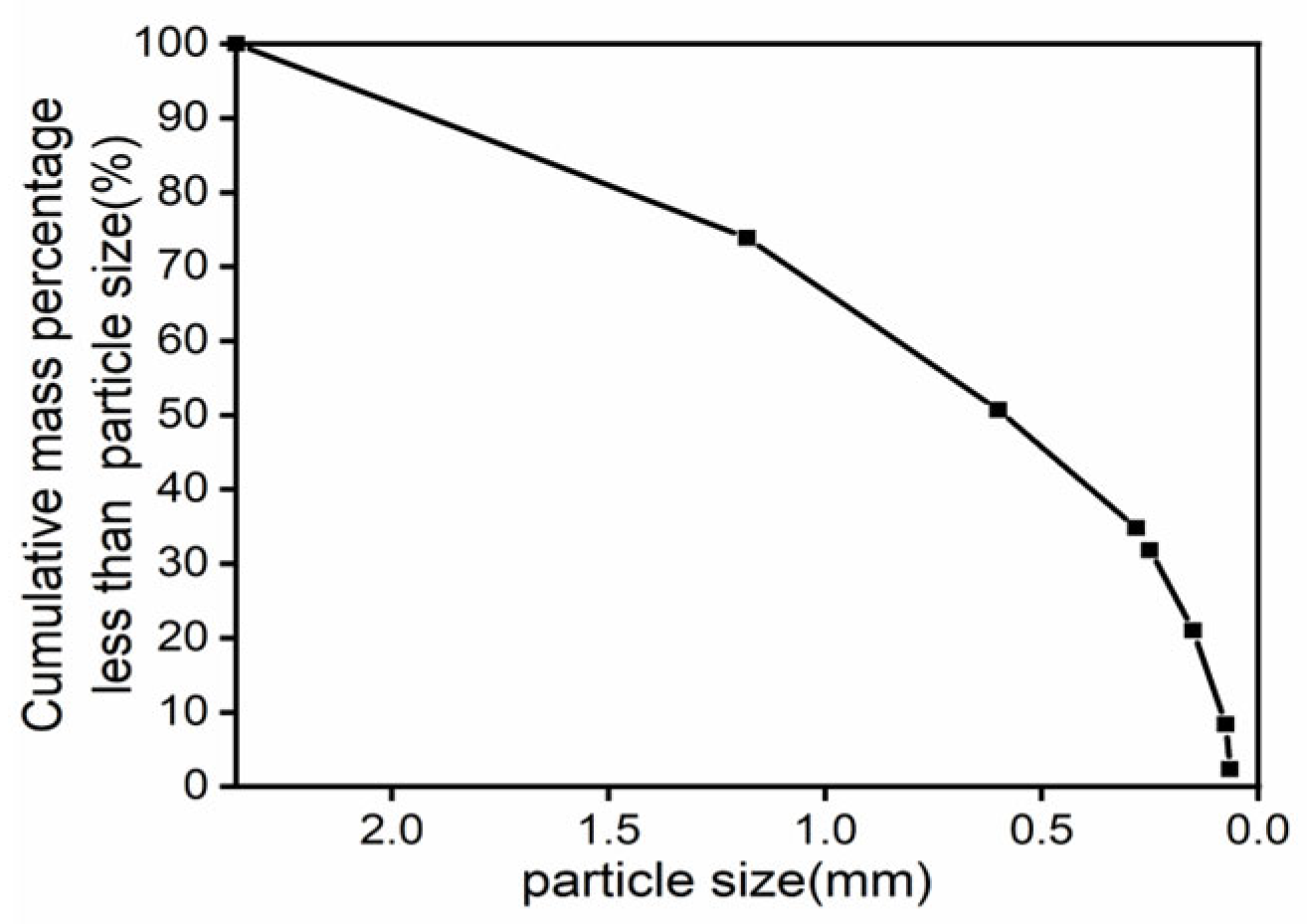
2.1. Site and Sample Descriptions

The low-grade uranium–gold polymetallic ore sample was taken from the ‘Ma’anshan Mine Research Institute, Anhui Province, China. It was separated into particle-size fractions after air drying. The particle size distribution is shown in Figure 1. On the basis of Figure 1, it is clear that the sand used in the test has a large particle size distribution and contains a high percentage of large particles, which suggests it is a coarse sand with poor gradation. According to the XRF analysis, Table 1 illustrates the main chemical composition of the uranium tailings.
The metakaolin was produced in Inner Mongolia, China, with a whiteness of 80%, an average particle size of 1 μm, and a specific surface area of 20 m2/g; the main chemical composition of metakaolin is displayed in Table 2.
Sodium silicate was from the Yourui Refractory, model SP38. The main chemical composition of sodium silicate is displayed in Table 3.
The analytically pure sodium hydroxide used was flaked, with a net content ≥ 95.0%. CaCl2 was produced by Tianjin Kemiou Chemical Reagents, with a net content of ≥96.0%.

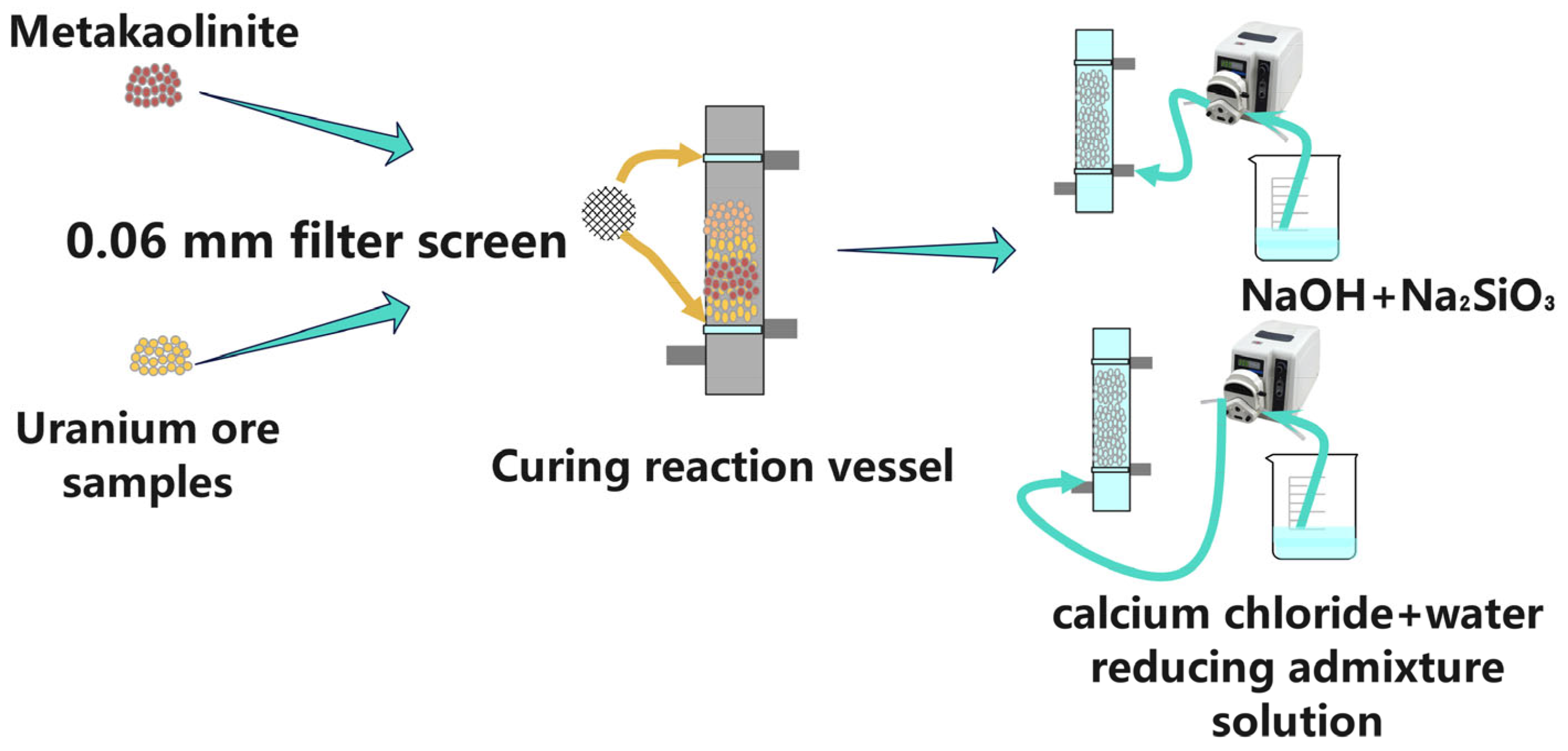
2.2. Batch Grouting Experiments

As shown in Figure 2, the device used to solidify uranium mill tailings operates at a constant temperature. In Figure 2, we can see that the reaction generator used in the test is a cylindrical container with an outer diameter of 45 mm, an inner diameter of 39 mm, and a height of 200 mm. The above dimensions are chosen to make the sample size meet the triaxial test requirements.
Before loading uranium tailings, three layers of gauze are placed on the bottom of the injector. This prevents fine particles from sinking into the grouting mouth during grouting. After compaction, the sample is grouted with a peristaltic pump. In order to reduce the disturbance caused by the mold removal process, a hot cutting knife was used.

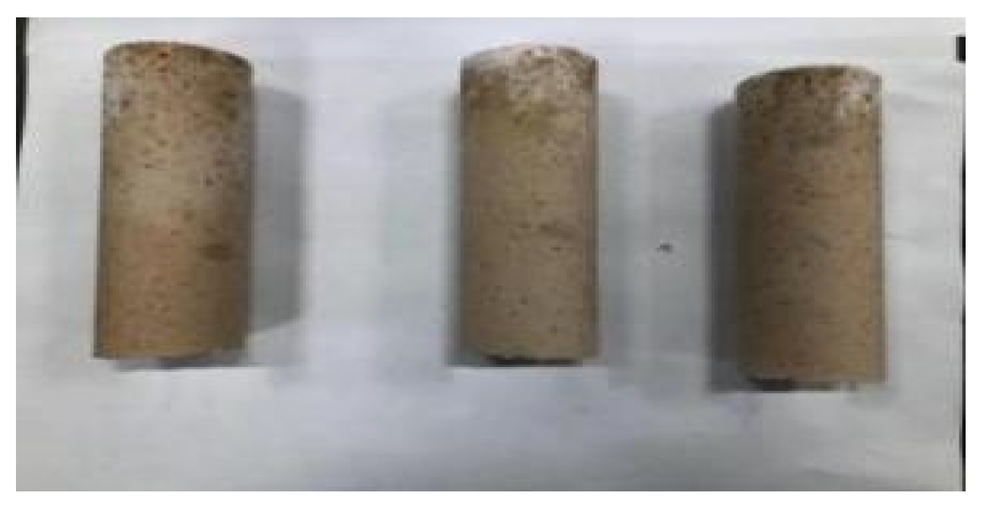
2.3. Test of Uranium Mill Tailings Solidified by Grouting

Tests were conducted in four batches of 3 days, 7 days, 14 days, and 28 days. The CaCl2 concentrations in each batch were set at 0%, 5%, 10%, 15%, 20% and 25%. Six gradients were performed. Three samples were used on each gradient. The addition of uranium tailings in each sample is up to 200 g. The bottom-up reverse grouting method is used for grouting. In the grouting stage, the above gradient concentration of CaCl2 was injected into each batch of samples at the grouting speed of 6 mL/min. The injection amount was 50 mL. Then, the prepared mixed slurry of NaOH, metakaolin, and water reducer was injected into the water glass. The amounts of each experimental sample are shown in Table 4 and Table 5. Accurately controlling the grouting amount and pump speed using a peristaltic pump can ensure uniform grout distribution in the interstitial space of uranium slag. After undergoing a reaction for 3 h, the grout is put in the curing box for maintenance. After reaching the set curing time, the sample is taken out, and the mold is removed for further experiments.

2.4. Triaxial Strength Test

In subsequent batches of uranium tailings, each batch was dried at room temperature and cut using a hot cutter after curing for 3 days, 7 days, 14 days, and 28 days. Ore samples were taken out of the lab and put into the triaxial test instrument. As shown in Figure 3, the confining pressure was set at 100 MPa, 200 MPa, and 300 MPa for the triaxial shear test. As shown in Figure 4, the sample with 20% CaCl2 injection volume for 28 days is dense and smooth.

2.5. Uranium Concentration Content Change Test

The samples were placed in plastic bottles marked with a scale with maintenance periods of 3, 7, 14, and 28 days. In order to ensure all samples were submerged, 500 mL of deionized water was added. To determine the uranium concentration, a soaking solution was taken after 30 h of soaking. However, as shown in Figure 5, even if the soaking solution is filtered through a 0.22 m filter head, precipitation still occurs when preparing uranium samples, which cannot be accurately measured using conventional UV spectrophotometry since they contain fine solid particles such as metakaolin. Hence, the filtered extracts must be digested, and the steps are as follows: adding 2.5 mL concentrated nitric acid to 50 mL leachate, heating and nitrating to about 5 mL volume, cooling, adding 2.5 mL concentrated nitric acid and a small amount of 1 mL perchloric acid, heating and digesting until nearly dry, and then dissolving the residue with 2% nitric acid, passing the filter again with 2% nitric acid in a constant volume of 25 mL after cooling. After digestion, the leachate was subjected to ICP-OES testing for uranium concentration.

2.6. Radon Exhalation Rate Test

Based on the sample size of the solidified uranium mill tailings, a radon collecting hood with a volume of 1400 mL was designed. The solidified uranium mill tailings column was put in the radon collection tank. It was then connected to the RAD-7 radon detector through a connecting pipe. After checking the air-tightness of the device, the radon tester was turned on; counting began after the cycle was stable, and the radon concentration was continuously measured after 30 h. Figure 6 shows the test setup.

2.7. XRD, XPS Test Experiment

The solidified body samples were crushed, dried, and put into a ball mill for a grinding treatment. The rotation speed was set to 500 rpm and a 200-mesh sieve was selected for sieving after 30 min.
The maintenance cycle was 7 days and 28 days, and the solidified body with a CaCl2 injection amount of 20% was dried for 48 h and then put into a ball mill. The rotation speed was set to 500 rpm. After grinding for 30 min, the sample was taken out and passed through a 200-mesh sieve and then tested using XPS.

3. Results and Discussions

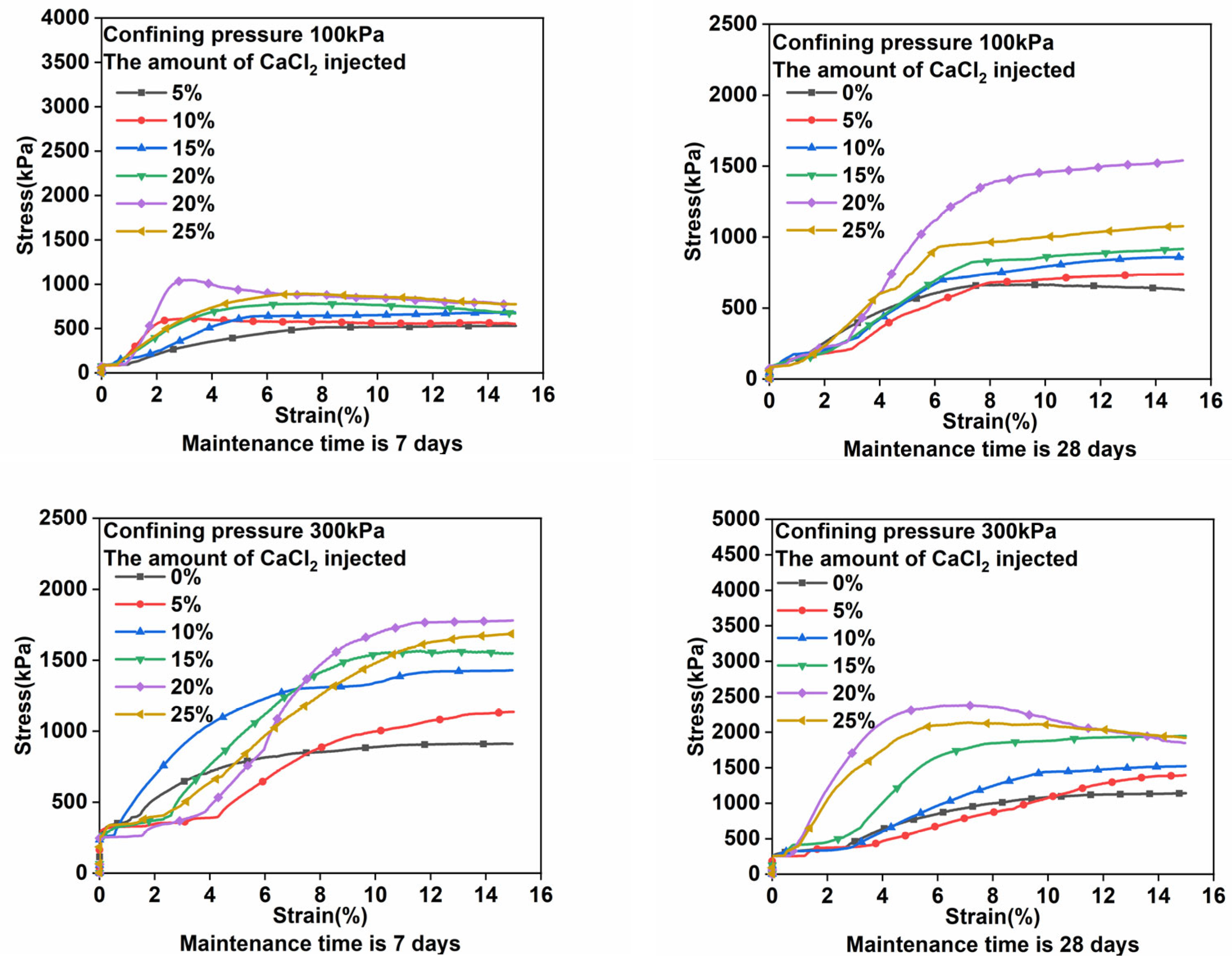
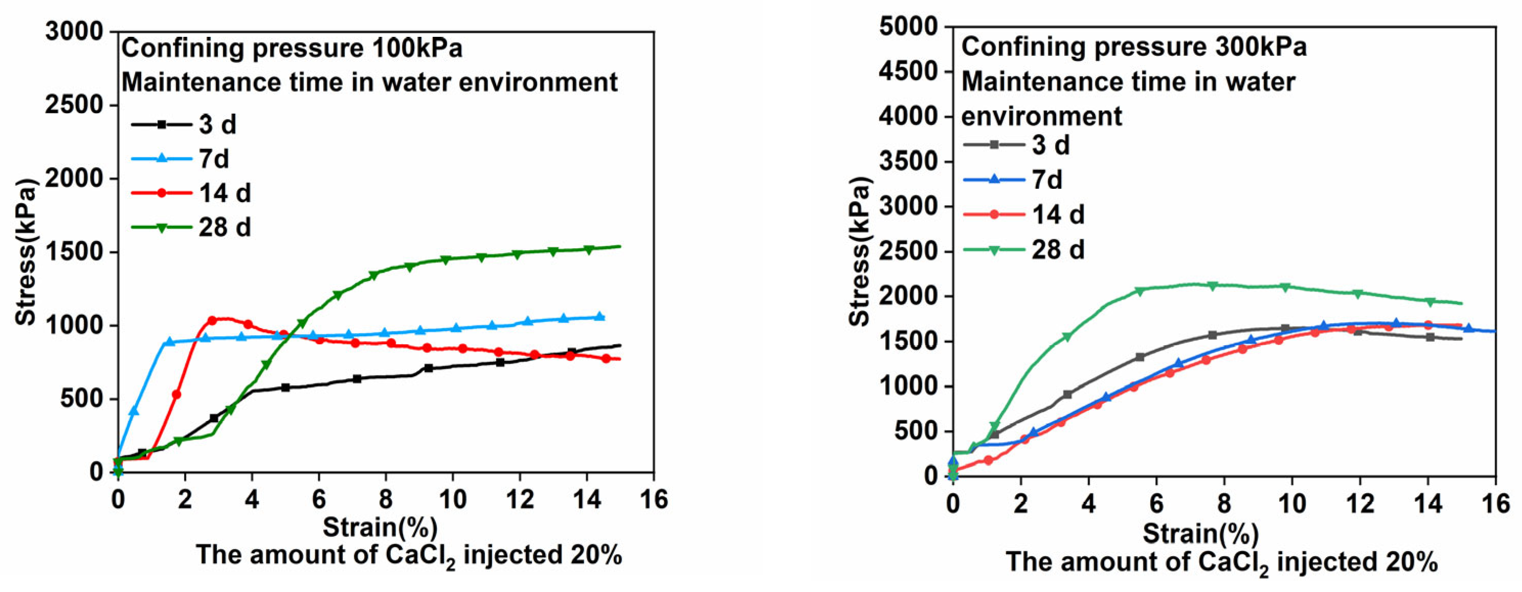
3.1. Triaxial Compression Test Results and Analyses

As shown in Figure 7 below, stress and strain curves of a tailing sand column (diameter: height = 39.1 mm:79 mm) at different confining pressures (100 kPa, 200 kPa, 300 kPa) with CaCl2 content were compared. As the CaCl2 content increases, the peak compressive strength first increases then decreases, with 20% CaCl2 supplying the extreme value. The triaxial compressive strength of a solidified body can be improved by adding CaCl2, but it can also be decreased once it reaches a critical value. The excess of CaCl2 during grouting prevents the reaction from fully taking place, leading to defects in the solidified body. As a result, bonding stresses are unevenly distributed in the body, and local stresses concentrate, resulting in lower pressure resistance.
Triaxial compressive strength and stress–strain curves of the uranium mill tailings solidified by CaCl2 grouting are shown in Figure 7; the entire stress–strain curve is seen to move upward with the extension of the solidifying period. It consists of four stages. When the load was applied initially, the axial stress increased gradually while the axial strain remained constant, indicating initial stress. The second stage showed the axial strain increasing while the axial stress stayed constant, showing pore compaction. In the third stage, the axial stress rapidly increased with axial strain and then peaked. In the fourth stage of the curve’s development, the axial stress declined slowly with an increase in axial strain, showing that cracks have formed in the specimen, but it retained residual strength. Generally, the curves follow similar trends under the same confining pressure; in the third stage, the stress developed more slowly, with strain under 100 kPa rather than under 300 kPa. The peak stress and initial stress under 100 kPa confining pressure were smaller than those under 300 kPa confining pressure. Therefore, the solidification effect of grouting is depth dependent; it can be compared with different confining pressures, and the confining pressures of 100 kPa and 300 kPa were chosen as representative of shallow and deep underground uranium mill tailings, respectively.
According to the confining pressure of 100 kPa and the seven-day curing time, 530 kPa is the axial stress peak for uninjected CaCl2, while 1047 kPa is the axial stress peak with 20% CaCl2. We continued to increase the injection amount of CaCl2 to 25%; the strength decreased and was lower than when the CaCl2 injection was 20%. When the confining pressure is 100 kPa and the curing time is 28 days, peak stress is 665 kPa without CaCl2, and, when 20% CaCl2 is injected, the peak stress is 1541 kPa and the strength is increased by 2.3 times. When the confining pressure is 300 kPa and the cure time is seven days, the axial stress peaks at 912 kPa when no CaCl2 is injected and at 2378 kPa when 20% CaCl2 is injected.

3.2. Hydraulicity Strength Test

The solidified body was submerged in the bottle with deionized water with a 20% CaCl2 injection after grouting. After setting for 3, 7, 14 and 28 days, a triaxial strength test was conducted, as shown in Figure 8 and Figure 9.
Based on Figure 8 and Figure 9, the solidified body of uranium tailings shows no looseness after soaking, and its surface becomes more compact, indicating that the sample cures in a water environment. Figure 8 shows the strength test. As shown in Figure 9, the strength of the solidified body with 20% CaCl2 injection curing in a water environment for three, seven, fourteen, and twenty-eight days is significantly enhanced when the confining pressure is 100 kPa and 300 kPa, further demonstrating that Formulas (1)–(6) are correct. In addition, the hydraulic reaction contributes to a significant strength increase in the solidified body.

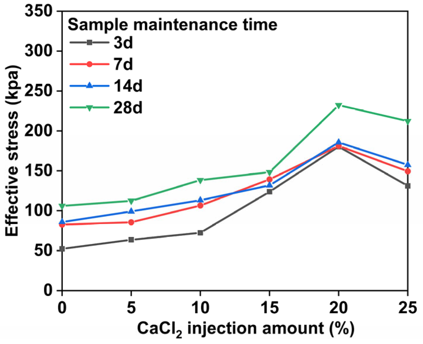
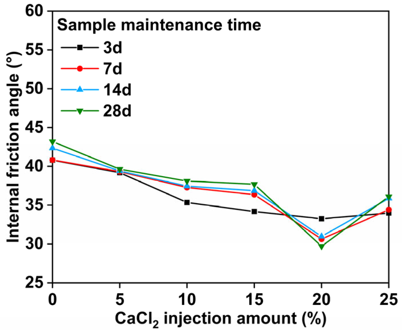
3.3. Analysis of Effective Stress and Internal Friction Angle Results

To further analyze the influence of CaCl2 injection quantity on the strength of the solidified body, the Mohr stress circle is used to determine the effective stress and internal friction angle. Taking the CaCl2 injection amount in the solidified body as the horizontal axis and the effective stress and internal friction angle as the vertical axis, the relationship curves between the CaCl2 injection amount and effective stress and internal friction angle in the solidified body are plotted (Figure 10 and Figure 11). Figure 10 shows that, with an increasing CaCl2 dosage, the effective stress of the solidified body gradually increases along with the growth rate, which peaks at 20% and then diminishes. This is mainly related to the strength of the hydration reaction of CaCl2 in the curing process. Within a suitable range, with the increase in the amount of CaCl2 injected, the hydration reaction is more sufficient. The reaction mechanism is shown in Formulas (7) and (8). When the injection amount of CaCl2 is higher than a certain threshold, the properties of CaCl2 are stable and exhibit good hygroscopic performance. It can absorb the moisture in humid air, and the solidified body can be completely dehydrated only when the temperature is above 260 °C. The chemical bond force results in the weakening of its mechanical properties.
Uranium tailings are solidified with metakaolin, CaCl2, NaOH, and sodium silicate as the main raw materials. The main factor is that the essential components of metakaolin and uranium tailings are SiO2 and Al2O3. Under alkali activation, N-A-S-H and C-A-S-H gel materials are generated. These materials react with water to form hydrated calcium silicate (C-S-H) and hydrated calcium aluminate (C-A-H). The reaction formula is as follows: (1)–(6)):
CaCl2 + SiO2 + 2NaOH → CaSiO3 + H2O + NaCl
CaCl2 + NaOH → NaCl + Ca(OH)2
Ca(OH)2 → Ca2+ + 2OH
Ca2+ + Si(OH)4 → C-S-H
Ca2+ + Al(OH)3 → C-A-H
Al(OH)3 + Ca2+ + CaSiO3·2H2O → 3CaO·Al2O3·3CaSiO3·32H2O
According to the above reaction formulas, the hydration products C-A-H, C-S-H, and CaSiO3·2H2O were obtained in the experiment. The N-A-S-H and C-A-S-H networks were formed under the continuous action of alkali excitation. This hydration reaction mechanism provides material support for the subsequent reaction to form a hydraulic cementitious material, improving the mechanical properties of solidified uranium tailings:
2NaOH + SiO2 + CaCl2 = CaSiO3 + 2NaCl + H2O
CaCl2 + n H2O = CaCl2·n H2O (n = 1, 2, 3, 4, 5, 6)
Figure 11 shows the relationship between the CaCl2 injection amount and the internal friction angle. Figure 11 shows that, as CaCl2 injection amount is increased, the internal friction angle of the solidified body gradually decreases. This is mainly due to the free iron oxide in the solidified body. The free iron oxide is the secondary mineral composition of metakaolin and uranium tailings, and the particles are very fine. It is extremely easy to form a sol colloid with water. The cementation is in the form of thin films and discontinuous single particles, which easily change according to the external environment. The essence of cementation between iron oxide colloid and the solidified body is to control the microstructure of the solidified body via the bonding state and bonding strength between the solidified body particles, thereby affecting the mechanical properties of the solidified body.
With the increase in CaCl2 injections up to 25%, the alkalinity of the solidified body increases, and the solubility of amorphous iron decreases rapidly under alkaline conditions, resulting in the inhibition of the formation of crystalline iron oxide in the solidified body and the weakening of the bonding performance between the structural connection points and the skeleton support of the solidified body particles. At the same time, the SiO2 in the uranium tailings and metakaolin components will react under alkaline conditions, and the reaction equation is shown in Formula (7). The bridge between the colloids is destroyed due to the loss of SiO2; the Fe-Al-Ca mixed oxide colloids were formed by incomplete exchange between the Fe-Al oxide colloids, which played a major role in cementation, and the calcium ions injected into CaCl2. The original oxide colloid adsorption equilibrium transformation of the solidified body was not complete, which destroyed the close structure between the solidified body particles and reduced the internal friction angle of the solidified body.

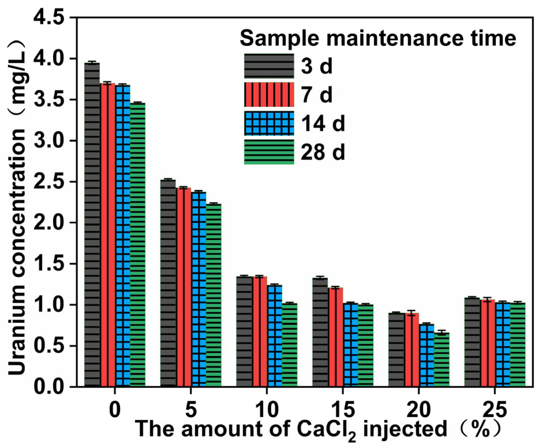
3.4. Dissolved U Concentration and Analysis

To begin the experiment, 200 g of the test sample was immersed in the bottle for 30 h. The soaking solution was extracted, filtered, and digested. The initial concentration of uranium tailings was 5.30 mg/L according to the UV spectrophotometer, and the content was high. When the CaCl2 injection was increased, the uranium concentration first decreased and then increased linearly. As shown in Figure 12, when the CaCl2 injection amount was 20%, the uranium concentration reached the lowest point, decreased to 0.68497 mg/L, then decreased by 88%, and the decrease was obvious. The results show that the CaCl2, NaOH, sodium silicate, and metakaolin consolidation of uranium tailing bodies can significantly improve the anti-leaching ability of uranium tailings’ slag uranium.
Due to the nature of the alkali-excited uranium tailings’ gelling products, they mainly consist of amorphous N-A-S-H and C-A-S-H gels that form a three-dimensional network structure when cemented together. These highly polymerized products comprise complex uranamide with a larger ionic radius. The ions are separated and sealed and form a stable structure with the unreacted particles in the solidified body, and the CaSiO3 product generated by the reaction of CaCl2 and Na2SiO3 fills the void structure between the particles, inhibiting the leaching of uranium. Moreover, the alkali-activated solidified uranium tailings leaching solution’s PH is alkaline; Ca2+ with two units of positive charge can play a role in the conducting charge and adsorption of uranium amide complex ions. At the same time, metakaolin and sodium silicate under alkali excitation resulted in the extension of gel products and the polymer chain structure, which enhanced the adsorption capacity of the uranium amide complex ions. Furthermore, Al2O3 in uranium tailings and metakaolin components and the injected CaCl2 solution generate Al(OH)3 and Ca(OH)2 and other colloids in an alkaline environment, providing a carrier for uranium precipitation. The precipitated diuranate can be adsorbed by N-A-S-H and C-A-S-H gels, so the leaching resistance of uranium tailings is significantly improved.

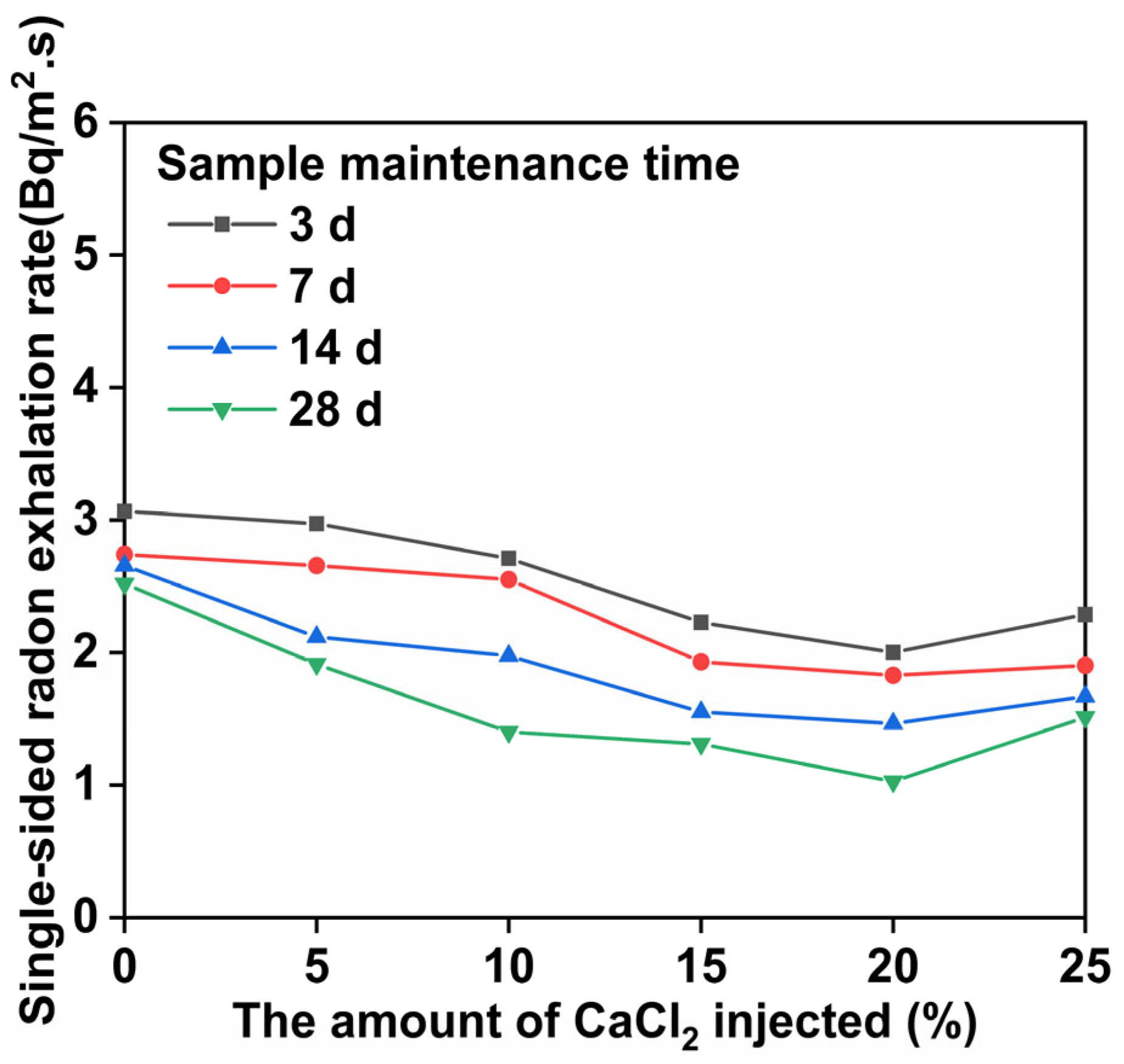
3.5. Results and Analysis of the Rn Exhalation Test

Figure 13 shows a variation curve of the concentration accumulated with the accumulation time of the solidified samples with different amounts of CaCl2.
Figure 13 illustrates the rapid drop in accumulated Rn concentration as a function of the accumulated Rn accumulation time during the early stage, and then a gradual or steady rise as time progresses. During the 28 days of curing time for the grouting of 20% CaCl2, the radon concentration decreased to its lowest. Formula (9) and Figure 14 show the radon exhalation rate of the solidified single-sided specimens. Figure 14 shows the calculated values. With increasing grouting CaCl2 and maintenance cycles, the Rn exhalation rate of the solidified bodies slowly slows down. The cumulative radon concentration tended to conform to linear relationships, and the slope was high when the CaCl2 injection rates were 0% or 10%. With CaCl2 injection rates of 15% and 20%, the slow growth of the cumulative radon concentration could be fitted by logarithms. The cumulative radon concentration at 29.5 h was 4253 Bq/m3, which was significantly lower than that of 8790 Bq/m3 without the CaCl2 injection, and the decrease value was 51.6%. Based on the relationship between the cumulative radon concentration and radon collection time, the following formula can be applied to the consolidated uranium tailings:
J i = 1 i C i × V i 10 6 × r 2 × 3600 t × 100 %
where Ji is the radon exhalation rate when the mass of injected CaCl2 is i%, Ci is the cumulative radon concentration when the mass of injected CaCl2 is i%, V is the volume of the collecting radon bottle, r is the bottom area of the collecting radon bottle, and t is the monitoring time.
As shown in Figure 14, during the curing period of 28 days and with 20% CaCl2 mass, the single-sided radon exhalation rate of the sample decreased most. When CaCl2, NaOH, sodium silicate, and metakaolin are added to the uranium tailings ore body, the radon exhalation reaches equilibrium in a short time. However, when the mass of CaCl2 was 25%, the single-sided radon exhalation rate increased. This is because CaCl2 has water absorption properties, which allow it to absorb the water in the air. The sample is deliquescent, and the particles that are not wrapped by the gel are deliquescent due to the contact with water, which reduces the compactness of the solidified body. Second, when the CaCl2 mass increases, chloride ions increase in the solidified body. When chloride ions are added to the solidified body in the appropriate amount, their density can be improved, but excessive chloride ions will erode the cementitious material, resulting in a decrease in mechanical properties and an increase in unilateral radon exhalation. Therefore, when the mass fraction of CaCl2 is 20%, the Rn exhalation rate can be significantly reduced.

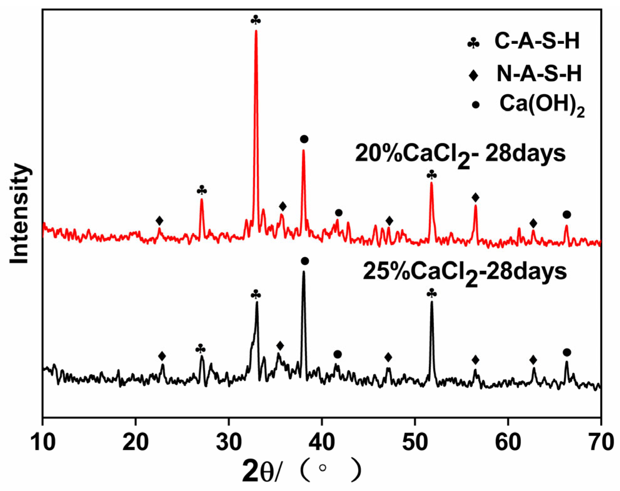
3.6. XRD Test Results Analysis

Figure 15 shows the XRD patterns when the content of CaCl2 is 20% and 25% and the curing period is 28 d. Figure 15 shows the XRD analysis of alkali-activated uranium tailings for different injected amounts of CaCl2. Curing takes 28 days. When CaCl2 is injected at a rate of 20%, a diffraction peak packet within 30–35° is obtained, which indicates that more N-A-S-H and C-A-S-H species were formed. However, the diffraction peak packets were lower when CaCl2 was injected at a rate of 25% than when it was injected at a rate of 20%.
CaCl2 was injected, and the characteristic peak of C-A-S-H was much higher than that of the 25% CaCl2 injection. However, when the content of CaCl2 was 25%, the characteristic peak of Ca(OH)2 was much higher than that when the amount of injected CaCl2 was 20%. This shows that the reaction system has too much CaCl2, which consumes the NaOH in the process of alkali excitation, resulting in overly low alkalinity. In uranium tailings and metakaolin, Si-O and Al-O bonds are difficult to break, resulting in a large reduction in dissolved products. It is difficult for the gel product to continue the polycondensation reaction, resulting in the reduction of the macromolecular structure of the N-A-S-H gel. Therefore, the strength of the system decreases, which is also a good explanation for the decrease in strength when the triaxial strength test is carried out when the content of CaCl2 is 25%.

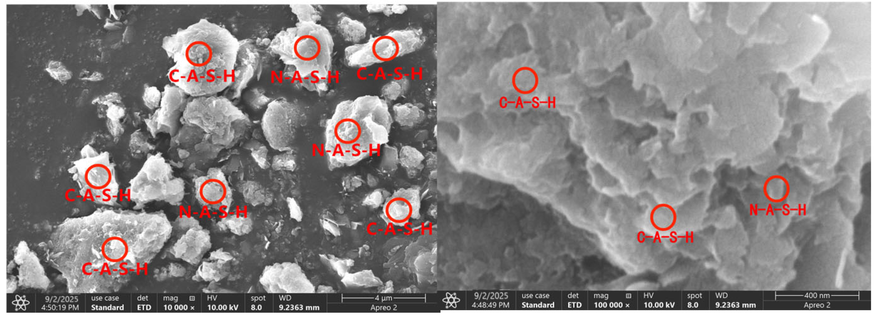
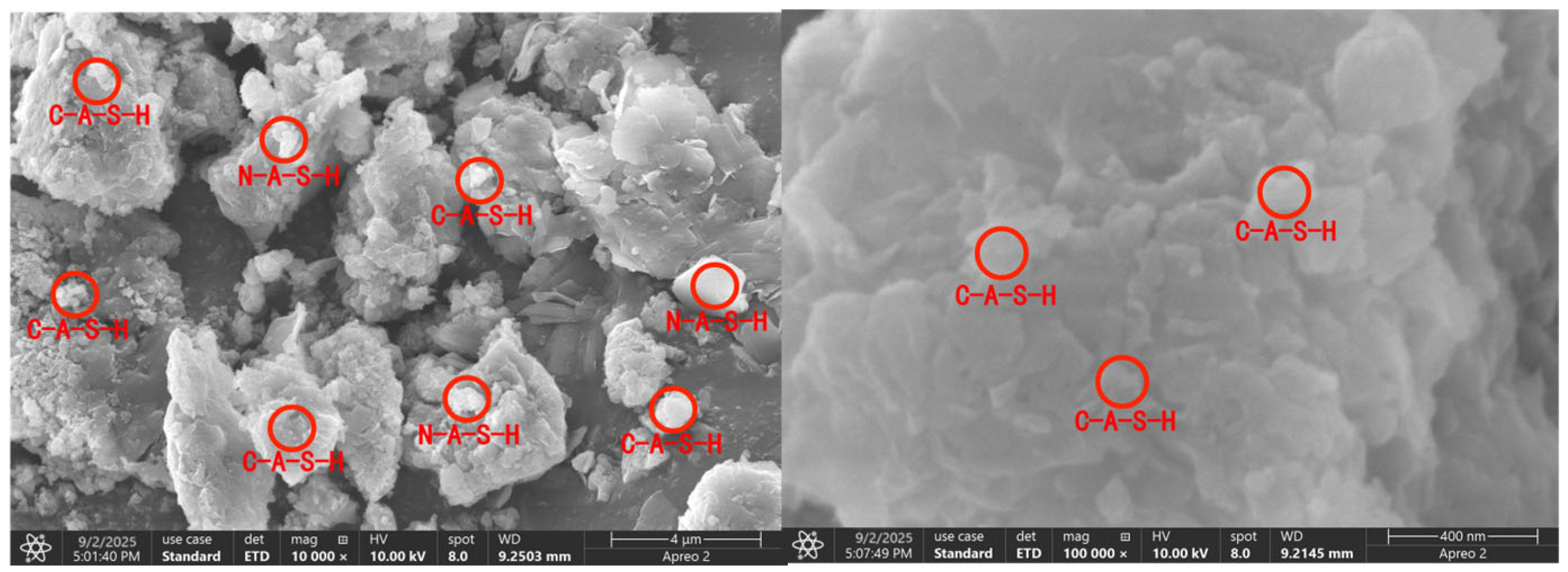
3.7. Microstructure Analysis

The main components of metakaolin are SiO2. Under the excitation of NaOH, Al2O3 will break Si-O and Al-O, and, at the same time, Al(OH)3 and H2SiO4 mixed sols are generated in aqueous solution. Through polycondensation, these newly formed Si-O tetrahedron and Al-O tetrahedron units will form polymers from the broken Si-O and Al-O. During the polymerization process, a large amount of water is generated, which provides the conditions for the next reaction. According to Davidovist [38,39], the reaction equation of the geopolymer is as shown in Formula (10):
MX[-(Si-O2)Z-Al-O-]n·wH2O
where M represents basic cations; x represents the number of basic cations; z represents the molar ratio of silicon to aluminum; n represents the degree of polymerization; and w represents the content of crystal water.
( SiO 5 . Al 2 O 2 ) n + wSiO 2 + H 2 O + NaOH ( Na ) 2 n ( OH ) 3 - Si - O - Al - O - Si - ( OH ) 3
| ( metakaolin ) ( OH ) 2 Na n ( OH ) 3 Si 2 AlO 3 ( OH ) 5 + NaOH Na n + 1 [ Si 2 AlO 4 ( OH ) 3 ] + H 2 O
Van Deventer et al. [40] studied the reaction of active silicon aluminum with alkali to form geopolymers in the strong alkali environment of NaOH, as shown in Reaction (11) and Reaction (12). According to Formulas (10)–(12), the material after the reaction forms a new material linked by ring molecules, improving its curing strength and compactness, thus preventing radioactive substances and heavy metal ions from leaching from the uranium tailings. Figure 16 and Figure 17 show the microstructure of the samples after the injection of 20% CaCl2 and after the curing periods of 7 days and 28 days. Figure 16 shows that, when the maintenance period is seven days, the cured body is loose and porous, and it does not have a tight connection with the matrix. Under alkali excitation, amorphous N-A-S-H and C-A-S-H gels are not fully aggregated. At this point, the uranium tailings and CaCl2 generating the gel particles are small and unevenly distributed, and there are still many voids between the solidified particles, resulting in the solidified samples being inadequately strong and leaching uranium at a high level. Figure 17 indicates that, after the curing time of 28 days, there are more N-A-S-H and C-A-S-H gels between the uranium tailings particles, which fill the gaps between the tailing particles, reduce the gaps between the particles, and improve the bonded body structure. This makes the solidified body much more compact and dense. It improves the microarchitecture, strengthens the solidified body, and prevents uranium from leaching.

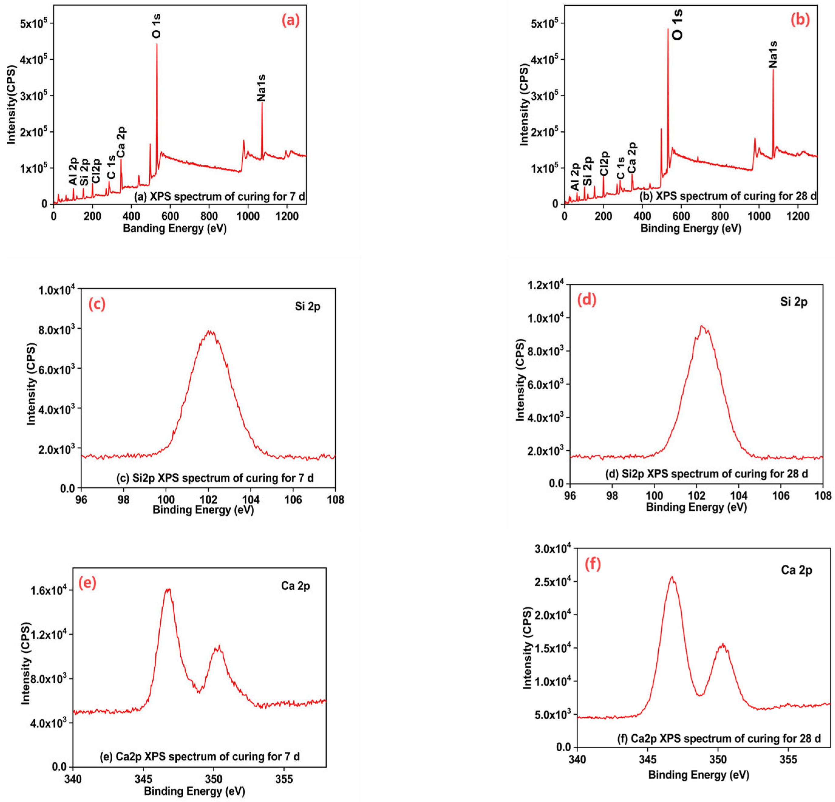
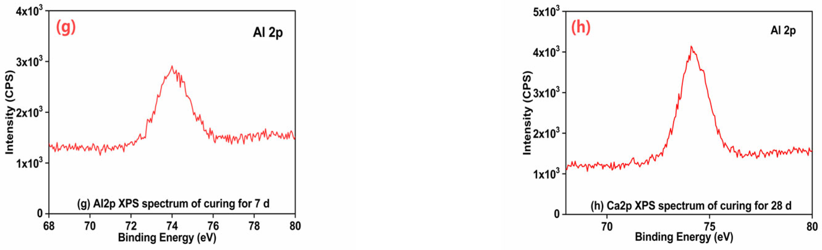
3.8. Analysis of the XPS Test Results

To further analyze the Si, Ca, and Al coordination bonds in these products, samples with 7-day and 28-day curing times and 20% CaCl2 injections were tested and analyzed using XPS. Figure 18 shows the analysis of the Si2p, Ca2p, and AI2p XPS spectrums. According to the comparison and analysis of Figure 18a,b, the samples with curing times of 7 and 28 days display the following characteristics. The samples with curing times of 7 days and 28 days show sharp peaks of Si2p, Ca2p, and AI2p. Samples cured for 28 days had significantly higher characteristic peaks than those cured for 7 days. Additionally, Si2p and AI2p appeared at 103 ev and 64 ev after 7 days and 153 ev and 102 ev after 28 days, respectively, indicating that the characteristic peak moved to the right and the hydration reaction was further accelerated. In light of Figure 18c,d, it is evident that the 103 ev and 153 ev characteristic peaks correspond to the chemical shift characteristics of Si2p tetracoordinate bonds. Furthermore, this shows that the AlO4 tetrahedra bonded to the SiO4 tetrahedra chain form a three-dimensional network structure. Figure 18g,h shows that the feature peak also shifts to the right, corresponding to AI2p’s four coordinate bonds. From Figure 18e,f, it is evident that there are two peaks in the XPS spectrum of Ca, which are Ca2p1/2 and Ca2p3/2. On the 7th day, Ca2p1/2 and Ca2p3/2 peaks were 16,102 and 11,019 counts, respectively, and on the 28th, they peaked at 25,627 and 15,705 counts. These values increased by 9525 and 4686 counts, indicating that the reaction involved more calcium substances, increasing the curing reaction’s activity. In addition, it was found that the change in the binding energy of Ca2p1/2 and Ca2p3/2 was in agreement with that of Si2p and AI2p, indicating a good correlation between their binding energies, leading to improved curing activity and increased body compactness and strength.

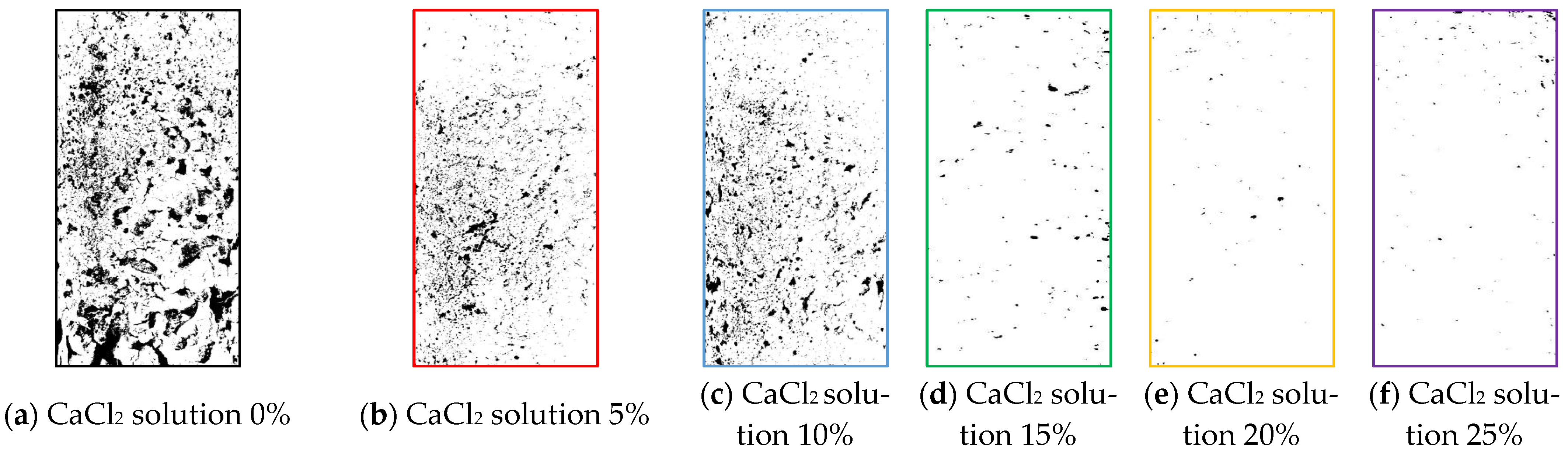
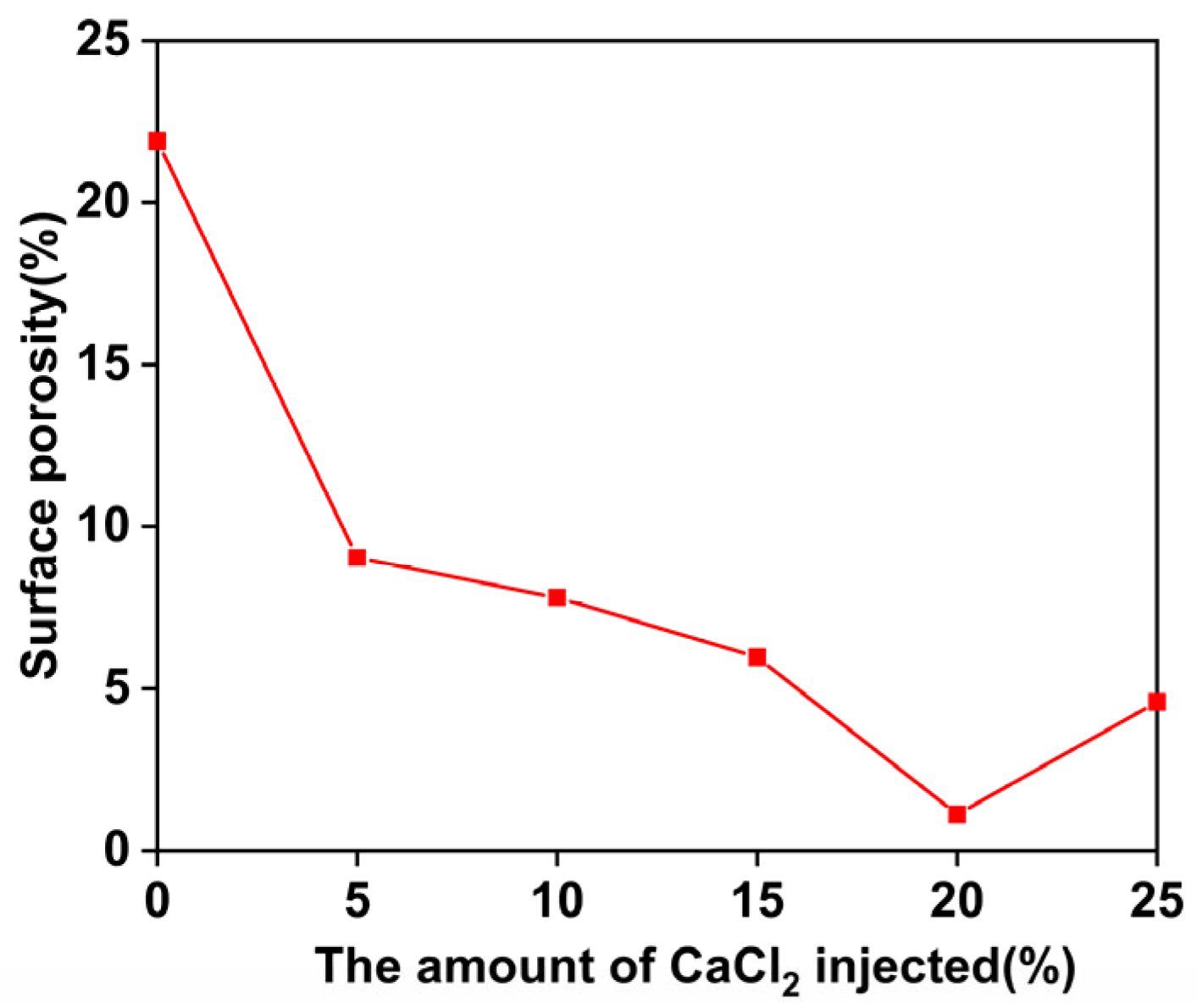
3.9. Microscopic Detection Image Analysis

For a further evaluation of CaCl2-NaOH–sodium silicate–metakaolin solidification, ImageJ2x software (Version 2.1.4.11) was used to process the image of the solidified body sample, and the surface porosity was calculated. Depending on the surface porosity of the sample, the reinforcement effect is evaluated. Figure 19 shows the amount of CaCl2 injected, with 0%, 5%, 10%, 15%, 20%, and 25% of the solidified body samples (Figure 19a–c,e,f). A porosity calculation was performed using ImageJ2x software and is shown in Figure 19.
According to Figure 19 and Figure 20, when the CaCl2 injection amount is 20%, the solidified body shows the lowest porosity. Compared with the case with no CaCl2 injection, the porosity decreased by 94%. Therefore, when the CaCl2 injection was 20%, the hydration reaction was more adequate, and a more uniform gel polymer was formed. There was a higher degree of polymerization and an increase in gel polymer aggregation near the macropores. In Figure 19f, a considerable number of closed mesopores are evidently formed on the surface of the solidified body, and the pore structure is enhanced significantly.

4. Conclusions

This study takes CaCl2, NaOH, water glass, metakaolin, and uranium tailings as the research objects. On the one hand, the CaCl2 solution of different mass fractions is injected by grouting, and, on the other hand, through the alkali excitation of NaOH, a gelling substance is generated in the solidified body so that the solidified body has the performance of hardening in the water environment, leading to the following conclusions:
(1)
The stronger the alkali-excited uranium tailing solidified body is, the higher the injection amount of CaCl2. If CaCl2 is injected at excessively high concentrations, the gel will erode and the mechanical properties of the solidified body will be affected. Therefore, the mass fraction of the injected amount of CaCl2 should be controlled at about 20%.
(2)
Under the assumption of the use of an appropriate amount of CaCl2, the longer the curing time, the higher the degree of polymerization, and the stronger the solidified body of alkali-activated uranium tailings. Compared with the strength before curing, the strength of the sample is doubled when the CaCl2 injection amount is 20% and the curing time is 28 days.
(3)
By adding excessive amounts of CaCl2, the cementation force and chemical bond force between the particles of the solidified body are both weakened, the structure of the solidified body is altered, and its mechanical properties are reduced. With a 25% injection of CaCl2, there is a 241 kPa difference between the 20% injection and the 25% injection.
(4)
The strengthening of uranium tailings using CaCl2–NaOH–sodium silicate–metakaolin can enhance the material’s mechanical properties, reduce the radon exhalation rate, and reduce the uranium leaching rate. Radon exhalation is reduced to 51.6% of the original sample, while uranium leaching is reduced by 88%.

Author Contributions

Conceptualization, X.F.; methodology, X.F. and Q.N.; software, Q.N.; validation, X.F. and Q.N.; formal analysis, Q.N.; investigation, X.F. and Q.N.; resources, X.F., And Q.N.; data curation, Q.N.; writing—original draft preparation, Q.N.; writing—review and editing, X.F.; visualization, Q.N.; supervision, X.F. and Q.N.; project administration, X.F.; funding acquisition, X.F. All authors have read and agreed to the published version of the manuscript.

Funding

Funding was granted by the National Key R&D Program of China (2023YFC2907800), the Major Innovation Program of Shandong Province of China (2021CXGC011206), the Program of China University of Mining and Technology, grant number 2023WLKXJ015, and the Postgraduate Research & Practice Innovation Program of Jiangsu Province, grant number KYCX23_2774.

Data Availability Statement

Date are contained within the article.

Acknowledgments

We thank our editors and reviewers for their efforts.

Conflicts of Interest

The authors declare no conflicts of interest.

References

  1. Horpibulsuk, S.; Rachan, R.; Chinkulkijniwat, A.; Raksachon, Y.; Suddeepong, A. Analysis of strength development in cement-stabilized silty clay from microstructural considerations. Constr. Build. Mater. 2010, 24, 2011–2021. [Google Scholar] [CrossRef]
  2. Wu, Y.; Hu, X.; Hu, R.; Shi, Y.; Han, T.; Yu, J. Experimental study on caustic soda-excited steel slag powder in silty soil. Chin. J. Geotech. Eng. 2017, 39, 2187–2194. [Google Scholar]
  3. Wang, D.; Wang, H.; Zou, W.; Wang, X.; Li, L. Study on the Microscopic Mechanism of Alkali-Excited Fly Ash Solidification Sludge. Chin. J. Rock Mech. Eng. 2019, 38, 3197–3205. [Google Scholar] [CrossRef]
  4. Yang, A.; Yan, S.; Du, D.; Zhao, R.; Liu, J. Experimental study on the effect of alkaline environment on the strength of solidified marine soft soil in Tianjin. Geotech. Mech. 2010, 31, 2930–2934. [Google Scholar] [CrossRef]
  5. Cuccia, V.; Freire, C.B.; Ladeira, A.C.Q. Radwaste oil immobilization in geopolymer after non-destructive treatment. Prog. Nucl. Energy 2020, 122, 103246. [Google Scholar] [CrossRef]
  6. Galhardi, J.A.; García-Tenorio, R.; Bonotto, D.M.; Francés, I.D.; Motta, J.G. Natural radionuclides in plants, soils, and sediments affected by uranium-rich coal mining activities in Brazil. J. Environ. Radioact. 2017, 177, 37–47. [Google Scholar] [CrossRef] [PubMed]
  7. Zhu, Y.; Ma, Q. Test and analysis of compressive performance of alkali-metakaolin-modified soil cement. J. Anhui Univ. Sci. Technol. (Nat. Sci. Ed.) 2020, 40, 35–40. [Google Scholar]
  8. Jiang, F.; Tan, B.; Wang, Z.; Liu, Y.; Hao, Y.; Zhang, C.; Wu, H.; Hong, C. Preparation and related properties of geopolymer-solidified uranium tailings bodies with various fibers and fiber content. Environ. Sci. Pollut. Res. 2022, 29, 20603–20616. [Google Scholar] [CrossRef]
  9. Zhang, K.; Yin, Z.; Cheng, G.; Zhou, J. Experimental study on the durability of concrete with polycarboxylate superplasticizer and different admixtures. Silic. Bull. 2018, 37, 2974–2978+2984. [Google Scholar] [CrossRef]
  10. Wang, Y.; Zhang, J.; Han, B. Analysis of Factors Affecting Bonding Properties of Water Glass-Calcium Chloride. Zhongzhou Coal 2012, 5–7. [Google Scholar]
  11. Zhang, F.; Yang, J.; Jin, W.; Zhang, L. Experimental study on the change law of permeability coefficient of water glass-calcium chloride solidified sandy soil. Sci. Technol. Bull. 2019, 35, 143–146+156. [Google Scholar] [CrossRef]
  12. Sawada, K.; Enokida, Y.; Tsukada, T. Oxidation and vitrification of aluminum with lead borate glass for low level radioactive waste treatment. J. Nucl. Sci. Technol. 2020, 57, 671–677. [Google Scholar] [CrossRef]
  13. Han, X.; Zhang, T.; He, B.; Xu, S. Analysis of Factors Affecting Strength of Fine Sand Body Reinforced by Sodium Glass-Calcium Chloride. Shaanxi Coal 2013, 32, 8–11. [Google Scholar]
  14. Southeast University; Zhejiang University. Soil Mechanics; China Construction Industry Press: Beijing, China, 2010; pp. 63–67. [Google Scholar]
  15. Thevanayagam, S.; Martin, G.R. Liquefaction in silty soils—Screening and remediation issues. Soil Dyn. Earthq. Eng. 2002, 22, 1035–1042. [Google Scholar] [CrossRef]
  16. Fredlund, D.G.; Morgenstern, N.R.; Widger, R.A. The shear strength of unsaturated soils. Can. Geotech. J. 1978, 15, 313–321. [Google Scholar] [CrossRef]
  17. Yang, B.; Liu, Y.; Wan, F.; Yang, T.; Feng, J.; Zhao, X.; Zheng, D. Experimental study on the influence of gradation characteristics on the permeability coefficient of sandy soil. J. Southwest Jiaotong Univ. 2016, 51, 855–861. [Google Scholar]
  18. Dang, F.; Liu, H.; Wang, X.; Xue, H.; Ma, Z. Research on empirical formula of permeability coefficient of cohesive soil based on effective void ratio. Chin. J. Rock Mech. Eng. 2015, 34, 1909–1917. [Google Scholar] [CrossRef]
  19. Xu, H.; Van Deventer, J.S. Geopolymerisation of multiple minerals. Miner. Eng. 2002, 15, 1131–1139. [Google Scholar] [CrossRef]
  20. Palomo, A.; Grutzeck, M.W.; Blanco, M.T. Alkali-activated fly ashes: A cement for the future. Cem. Concr. Res. 1999, 29, 1323–1329. [Google Scholar] [CrossRef]
  21. Lee, W.K.W.; Van Deverter, J.S.J. The effect of inorganic salt contamination on the strength and durability of geopolymers. Colloids Surf. A 2002, 211, 115–126. [Google Scholar] [CrossRef]
  22. Panagiotopoulou, C.; Kontori, E.; Perraki, T.; Kakali, G. Dissolution of alumisilicate and by-products in alkaline media. J. Mater. Sci. 2007, 42, 2967–2973. [Google Scholar] [CrossRef]
  23. Joseph, D.; Linwood, S.J. Early High-Strength Concrete Composition. EP Patent EP0153097 A2, 13 December 1989. [Google Scholar]
  24. Ye, J.; Zhang, W.; Shi, D. The coagulation-enhancing effect of calcium on alkali-stimulated cementitious materials. J. Silic. 2017, 45, 1101–1112. [Google Scholar] [CrossRef]
  25. Jaarsveld, J.; Deventer, J.; Lukey, G.C. The characterization of source materials in fly ash-based geopolymers. Mater. Lett. 2003, 57, 1272–1280. [Google Scholar] [CrossRef]
  26. Rakhimova, N.R.; Rakhimov, R.Z. Hydrated portland cement as an admixture to alkali-activated slag cement. Adv. Cem. Res. 2015, 27, 107–117. [Google Scholar] [CrossRef]
  27. Yliniemi, J.; Pesonen, J.; Tiainen, M.; Illikainen, M. Alkali activation of recovered fuel-biofuel fly ashfrom fluidised-bed combustion: Stabilisation/solidification of heavy metals. Waste Manag. 2015, 43, 273–282. [Google Scholar] [CrossRef] [PubMed]
  28. Feng, Y.; Chen, Q.; Zhou, Y.; Yang, Q.; Guo, H. Modification of glass structure via Cao addition in granulated copper slag to enhance its pozzolanic activity. Constr. Build. Mater. 2020, 240, 117970. [Google Scholar] [CrossRef]
  29. Jiao, H.Z.; Wang, S.F.; Wu, A.X.; Shen, H.M.; Wang, J.D. Cementitious property of NaAlO2-activated Ge slag as cement supplement. Int. J. Miner. Metall. Mater. 2019, 26, 1594–1603. [Google Scholar] [CrossRef]
  30. Mobasher, N.; Bernal, S.A.; Provis, J.L. Structural evolution of an alkali sulfate activated slag cement. J. Nucl. Mater. 2016, 468, 97–104. [Google Scholar] [CrossRef]
  31. Tantawy, M.A.; Ahmed, S.A.; Abdalla, E.M.; Qassim, M.I. Immobilization of copper ions-laden kaolin waste: Influence of thermal treatment on its immobilization in cement paste. J. Mater. Cycles Waste Manag. 2016, 18, 263–272. [Google Scholar] [CrossRef]
  32. Fernández-Jiménez, A.; Palomo, A.; Criado, M. Microstructure development of alkali-activated fly ash cement: A descriptive model. Cem. Concr. Res. 2005, 35, 1204–1209. [Google Scholar] [CrossRef]
  33. Glukhovsky, V.D.D. Soil Silicates, Their Properties, Technology and Manufacturing, and Fields of Application; Civil Engineering Institute: Kiev, Ukraine, 1965. [Google Scholar]
  34. Duxson, P.; Mallicoat, S.W.; Lukey, G.C.; Kriven, W.M.; Deventer, J.S.J.V. The effect of alkali and Si/Al ratio on the development of mechanical properties of metakaolin-based geopolymers. Colloids Surf. A 2007, 292, 8–20. [Google Scholar] [CrossRef]
  35. Ilia, D. Study on the Workability of Alkali-Slag Cementitious Materials. Master’s Thesis, Harbin Institute of Technology, Harbin, China, 2015. [Google Scholar] [CrossRef]
  36. Davidovits, J. Geopolymers and geopolymeric materials. J. Therm. Anal. 1989, 35, 429–441. [Google Scholar] [CrossRef]
  37. Shi, C. Strength, pore structure and permeability of alkali-activated slag mortars. Cem. Concr. Res. 1996, 26, 1789–1799. [Google Scholar] [CrossRef]
  38. Davidovist, J. Early High-Strength Mineral Polymer. US Patent No. 4509985, 9 April 1985. [Google Scholar]
  39. Davidovits, J. Synthetic Mineral Polymer Compound of the Silicoaluminates Family and Preparation Process. US Patent US4472199 A, 18 September 1984. [Google Scholar]
  40. Vandevenne, N.; Iacobescu, R.I.; Carleer, R.; Samyn, P.; D’Haen, J.; Pontikes, Y.; Schreurs, S.; Schroeyers, W. Alkali-activated materials for radionuclide immobilization and the effect of precursor composition on Cs/Sr retention. J. Nucl. Mater. 2018, 510, 575–584. [Google Scholar] [CrossRef]
Figure 1. Particle size distribution curve of the ore sample.
Minerals 15 00526 g001
Figure 2. Solidification device used in the uranium mill tailings test.
Minerals 15 00526 g002
Figure 3. Triaxial test of solidified uranium mill tailings.
Minerals 15 00526 g003
Figure 4. Sample maintenance period for 28 days.
Minerals 15 00526 g004
Figure 5. Uranium immersion test.
Minerals 15 00526 g005
Figure 6. Radon exhalation rate test.
Minerals 15 00526 g006
Figure 7. Triaxial compression strength and stress–strain relationship curve.
Minerals 15 00526 g007
Figure 8. Samples after soaking.
Minerals 15 00526 g008
Figure 9. Stress–strain relationship curve of water hardening strength test.
Minerals 15 00526 g009
Figure 10. Effective stress as a function of CaCl2.
Minerals 15 00526 g010
Figure 11. Internal friction angle as a function of CaCl2.
Minerals 15 00526 g011
Figure 12. Uranium concentration–CaCl2 relationship.
Minerals 15 00526 g012
Figure 13. Radon concentration measurements and fitting curve.
Minerals 15 00526 g013
Figure 14. Radon exhalation rate on single sides of each sample.
Minerals 15 00526 g014
Figure 15. XRD patterns of the different injection amounts of CaCl2 and the same maintenance time.
Minerals 15 00526 g015
Figure 16. CaCl2 injection amount 20%; uranium tail mine cured body SEM topography (7 d).
Minerals 15 00526 g016
Figure 17. CaCl2 injection amount 20%; uranium tail mine cured body SEM topography (28 d).
Minerals 15 00526 g017
Figure 18. Analysis of XPS test results. (a) XPS spectrum of curing for 7 d; (b) XPS spectrum of curing for 28 d; (c) Si2p XPS spectrum of curing for 7 d; (d) Si2p XPS spectrum of curing for 28 d; (e) Ca2p XPS spectrum of curing for 7 d; (f) Ca2p XPS spectrum of curing for 28 d; (g) Al2p XPS spectrum of curing for 7 d; (h) Al2p XPS spectrum of curing for 28 d.
Minerals 15 00526 g018aMinerals 15 00526 g018b
Figure 19. Images of samples with different injection amounts of CaCl2 for 28 days.
Minerals 15 00526 g019
Figure 20. Relationship between CaCl2 injection amount and porosity.
Minerals 15 00526 g020
Table 1. Chemical compositions of uranium tailings (w/%).
CompositionSiO2Fe2O3Al2O3UBeOOthers
Percentage/%74.358.537.180.0220.0728.93
Table 2. Chemical composition of metakaolin.
CompositionSiO2Fe2O3Al2O3NaO + K2O
Percentage/%540.8430.3
Table 3. Chemical compositions of water glass.
CategoriesSiO2Na2OBe/20 °CModulus
Parameters27.3%8.54%38.5Be3.3
Table 4. The incorporated amount of each material in the solidified uranium mill tailings.
CategoriesUranium TailingsMetakaolinNaOHWater Reducing AgentSodium Silicate
Parameters200 g54 g35 g2 g32 g
Table 5. CaCl2 injection volume in each experimental group.
Weight Percentage (%)510152025
Parameters (g)1020304050
Disclaimer/Publisher’s Note: The statements, opinions and data contained in all publications are solely those of the individual author(s) and contributor(s) and not of MDPI and/or the editor(s). MDPI and/or the editor(s) disclaim responsibility for any injury to people or property resulting from any ideas, methods, instructions or products referred to in the content.

