Article

Dynamic Mechanical Properties and Mesoscopic Characteristics of Cemented Tailings Backfill Under Cyclic Dynamic Loading

1
College of Mining Engineering, North China University of Science and Technology, Tangshan 063210, China
2
Hebei Province Key Laboratory of Mining Development and Security Technology, Tangshan 063210, China
3
College of Mechanical Engineering, North China University of Science and Technology, Tangshan 063210, China
*
Author to whom correspondence should be addressed.
Minerals 2025, 15(11), 1140; https://doi.org/10.3390/min15111140
Submission received: 20 September 2025 / Revised: 24 October 2025 / Accepted: 29 October 2025 / Published: 30 October 2025

Abstract

Cyclic dynamic loading significantly influences the dynamic mechanical properties of cemented tailings backfill (CTB). This study investigates the dynamic mechanical properties and mesoscopic characteristics of CTB under cyclic dynamic loading. Using a Split Hopkinson Pressure Bar (SHPB) system, impact tests were conducted on CTB specimens subjected to varying numbers of cyclic impacts. The dynamic peak compressive strength (DPCS), elastic modulus, energy evolution, and failure modes were analyzed. Additionally, computed tomography (CT) scanning and 3D reconstruction techniques were employed to examine the internal pore and crack distribution. Results indicate that cyclic impacts lead to a gradual reduction in DPCS and energy absorption capacity, while the elastic modulus shows strain-rate dependency. Mesostructural analysis reveals that cyclic loading promotes the initiation and propagation of microcracks. This study establishes a correlation between mesoscopic damage evolution and macroscopic mechanical degradation, providing insights into the durability and stability of CTB under repeated blasting disturbances in mining environments.

1. Introduction

The mining industry plays an important role in the national economic and social development. Shallow resources have been gradually depleted with the development of the mining industry. The exploitation of mineral resources is gradually moving deeper underground [1,2,3]. This trend has led to escalating environmental problems. Mining creates an extraction zone that can lead to surface collapse and pose a significant safety risk [4,5]. In addition, large quantities of solid waste from the mining process, such as tailings, occupy large areas [6,7]. This has also caused ecological problems such as water pollution and leaching of heavy metal ions [8,9]. Deslimed tailings are mixed with cement and water to form a low-concentration slurry. This slurry is transported via gravity or pumping into the underground goaf to form cemented tailings backfill (CTB). CTB can effectively control surface subsidence and reduce the area of tailings accumulation after being filled into the underground extraction zone. It also effectively reduces the rate of dilution and loss of ore during the mining process [10,11]. Therefore, backfill mining methods have been widely used worldwide [12].
CTB structures are subjected to loads induced by blasting and rock bursts. Therefore, the dynamic mechanical properties of CTB, such as its dynamic peak compressive strength (DPCS), deformation characteristics, and dynamic elastic modulus (DEM), need to be explored. The dynamic mechanical properties of CTB are commonly evaluated using Split Hopkinson Pressure Bar (SHPB) tests [13,14]. Chen et al. found that increasing the cement-tailings ratio, solid mass concentration, and curing age increased the DPCS and DEM of CTB [13]. Liu et al. investigated the dynamic mechanical properties of early-age CTB. The results showed that the deformation characteristics of early-age CTB changed from viscoelasticity to brittleness with the increase in curing age [15]. Particle size is also an important factor affecting the dynamic mechanical properties of CTB. Tan analyzed the effect of average particle size on the DPCS of CTB [16]. Lyu found that tailings gradation is also important in influencing the dynamic mechanical properties of CTB. When an effective supporting skeleton cannot be formed, CTB exhibits poor resistance to deformation [17]. The dynamic mechanical properties of CTB are also affected by strain rate. Cao found that the dynamic increase factor (DIF) of CTB increased with increasing strain rate in low- and intermediate-speed SHPB tests [18]. Zhang et al. conducted SHPB tests and found a positive correlation between DPCS and strain rate [19]. Han et al. conducted SHPB tests on CTB and concluded that DPCS could be improved with increasing strain rate [20]. Wu et al. showed that increasing the strain rate improves the DPCS of CTB, and the strength of CTB under high strain rate (dynamic loading) is twice that under static loading [21]. Hou et al. also obtained a similar relationship between strain rate and DPCS of CTB. In addition, the damage evolution and energy dissipation of CTB were analyzed [10]. Recently, many studies have focused on using fibers to enhance the strength of CTB [22,23]. Adding appropriate amounts of polypropylene fibers to CTB could improve its strength-deformation capacity [24,25]. These studies are important for maintaining the stability of CTB. However, most of these studies were conducted under single loading conditions. During the second-step mining of stopes, the dynamic disturbance caused by blasting operations is multiple. The internal damage of CTB gradually accumulates and may eventually cause collapse under such repeated blasting disturbances [26]. Tan et al. conducted cyclic impact tests on CTB and obtained its DPCS evolution law [27]. By carrying out the impact tests, Shu et al. pointed out that the DPCS shows a nonlinear decrease trend with the increasing dynamic impact number [28]. Liao et al. found that under cyclic impact, as the fiber content increased, the dynamic mechanical properties of the shotcrete improved [29]. These studies focused more on the macroscopic dynamic mechanical properties of CTB. CTB is an artificial material containing a large number of pores and microcracks [30]. These mesostructures can have important effects on the macroscopic dynamic mechanical properties of CTB. Research on CTB should focus more on its internal mesoscopic changes under external dynamic loading. The changes in macroscopic dynamic mechanical properties resulting from mesoscopic changes should be investigated. Cao et al. established a relationship between the uniaxial compressive strength of CTB and mesostructural parameters using CT scanning [31,32]. Although extensive research has elucidated the effects of factors such as material proportions, strain rate, and fiber reinforcement on the macroscopic dynamic mechanical properties of CTB under single-impact loading, these studies struggle to fully simulate the complex conditions of repeated blasting disturbances encountered in actual mining. During operations such as two-step mining, blasting in adjacent areas generates multiple dynamic disturbances, leading to continuous accumulation of internal damage within CTB and potentially triggering unstable failure. Therefore, it is necessary to investigate the degradation patterns of CTB’s macroscopic mechanical properties under cyclic impact loading and to clarify the evolution of its internal microstructure during the failure process. Safari and Taheri analyzed the mechanical and microstructural behavior of cemented paste backfill (CPB) under cyclic loading [33]. However, further research is needed to investigate the relationship between the changes in mechanical properties and microstructural changes in CTB under cyclic impact loading. This will help clarify the damage mechanism of CTB subjected to repeated blasting actions.
In this paper, impact tests were conducted on CTB subjected to a different number of impacts using the SHPB test apparatus. The deformation characteristics, strength characteristics, and failure modes of post-impact CTB were analyzed. Post-impact CTB were also processed by combining CT scanning to acquire mesoscopic characteristics and damage. Finally, the connection between mesoscopic characteristics and dynamical mechanical properties was analyzed.

2. Materials and Method

2.1. Experimental Materials

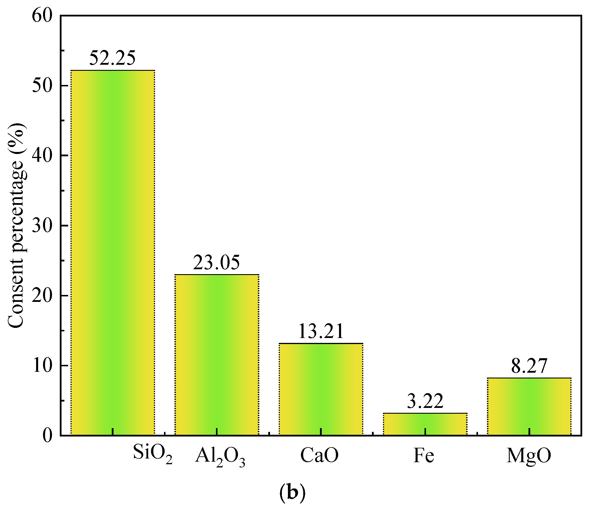
Unclassified tailings samples were obtained from a metalliferous mine in China. The tailings were dried in an oven at 100 °C for 24 h. The particle size distribution of tailings is an important factor affecting the mechanical properties of the CTB. The particle size distribution of the tailings was determined using a fully automatic laser particle size analyzer. Figure 1a presents the size distribution diagrams of tailings sample. The particle size range of the tailings is between 1 and 460 μm. The average particle size is 148 μm, with about 5% of particles smaller than 20 μm. A relatively high proportion of coarse particles (>75 μm; 88%) was identified in the tailings. The content of silt particles (5–75 μm) is relatively low, accounting for 8%. The lowest content of clay particles (<5 μm) is 4%. The tailings density is established to be 2.23 g/cm3. Figure 1b chemically reveals the primary composition of the tailings. The main component within tailings is SiO2 (52.25%). Al2O3, CaO, Fe2O3 and MgO account for 23.05%, 13.21%, 3.22% and 8.27%, respectively. The micro-active SiO2 and Al2O3 react with Ca (OH)2, forming ettringite and hydrated calcium silicate and aluminate gels, effectively filling voids and enhancing compressive strength [34]. CaO can provide sufficient Ca (OH)2 for the hydration reaction [35]. Figure 2 presents the tailings sample’s particle morphology. The tailing particles are mostly granular and have relatively rough surface, which benefits the strength development of CTB.

2.2. Specimen Preparation

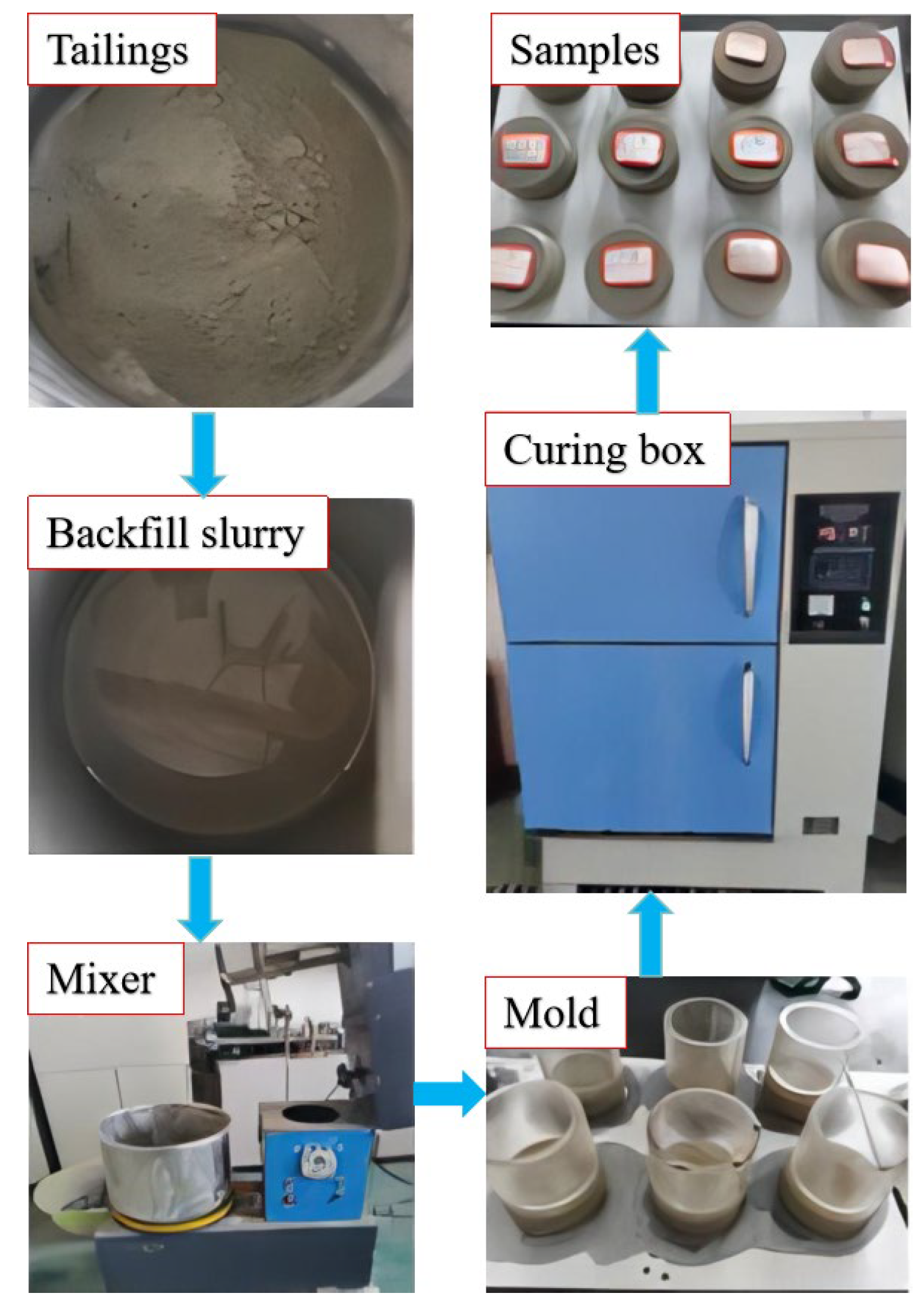
For this study, specimens were prepared with a cement-to-tailings ratio of 1:4 and a solid concentration of 72 wt%. This set of parameters was selected to align with the actual conditions of the study mine. The tailings, cement, and tap water were weighed using a standard electronic scale. To ensure thorough mixing, the tailings and cement were dry-mixed for 5 min. Then, an appropriate amount of water was added and mixed for 10 min. The tailings, cement and water were made into a uniformly mixed filling slurry. The uniform slurry was poured into molds (Φ 50 mm × 25 mm). The CTB specimens were demolded after 24 h. They were placed in a curing box for 28 days. The temperature and humidity of the curing box were 20 °C and 90%, respectively. The specimens were polished at both ends after 28 days. The preparation process of CTB specimens is shown in Figure 3.

2.3. Testing Equipment

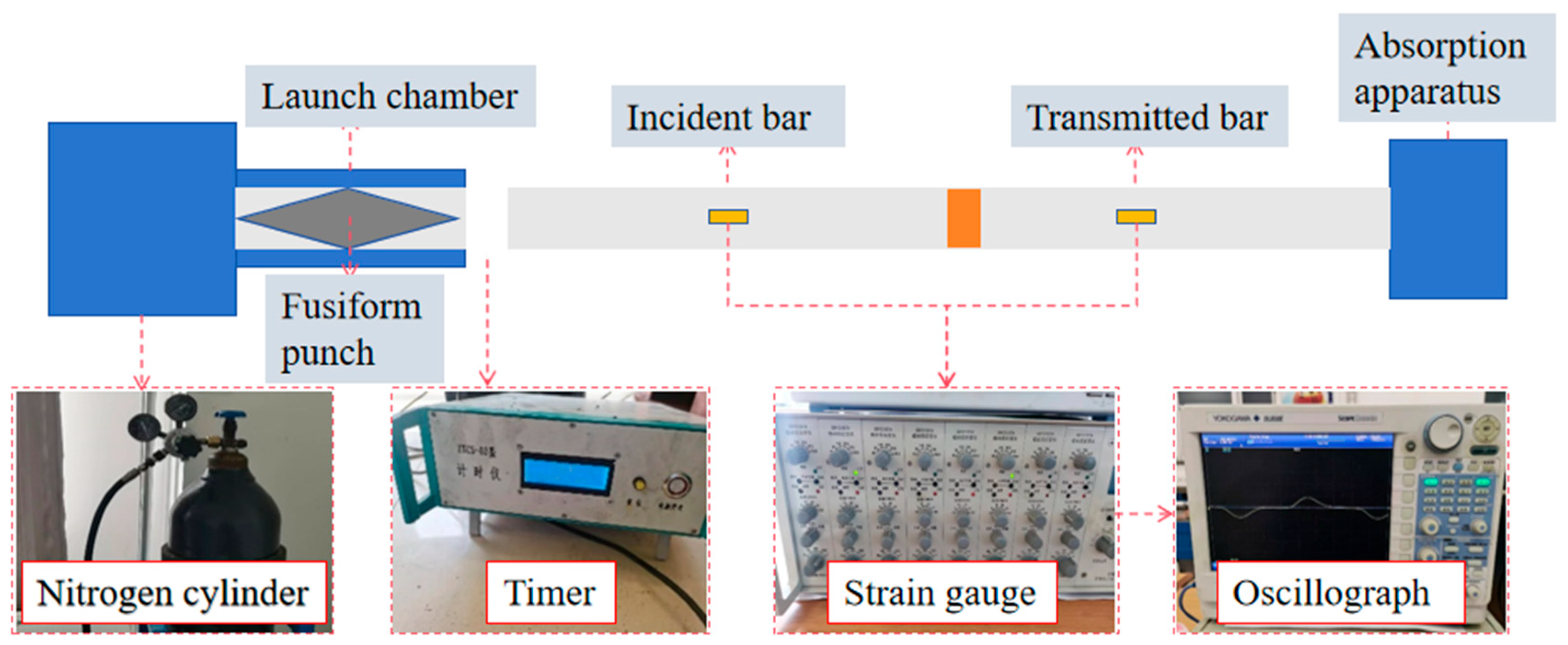
The impact tests were conducted using the split Hopkinson pressure bar (SHPB) test system at North China University of Science and Technology. The schematic of the SHPB system is shown in Figure 4. It is mainly composed of a launch chamber, a fusiform punch, an incident bar, a transmitted bar, an absorption apparatus, a nitrogen cylinder, a timer, strain gauges, and an oscillograph. The incident bar and the transmitted bar are made of 40 Cr alloy steel. The bars have a diameter of 50 mm, a density of 7579 kg/m3, a longitudinal wave speed of 5198 m/s, and an elastic modulus of 240 GPa. Both test bars are fixed horizontally in the adjustment bracket. The CTB specimen is placed between the two test bars. The system can reach gas pressures in the range of 0 to 4 MPa.
When a high-pressure gas propels the spindle punch to strike the incident bar, a compression pulse is generated within the incident bar. As this pulse propagates to the interface between the incident bar and the CTB specimen, part of the pulse is reflected back into the incident bar, forming a reflected wave, while another portion is transmitted through the CTB specimen to generate a transmitted compression pulse in the transmission bar. Strain gauges affixed to both the incident bar and transmission bar capture the incident, reflected, and transmitted wave signals. Based on one-dimensional stress wave theory, the acquired strain signals were processed using the “three-wave method” to calculate the specimen’s stress, strain, strain rate, and absorbed energy according to the following formulas:
σ ( t ) = A e 2 A s [ σ I σ R ( T ) + σ T ( t ) ]
ε ( t ) = 1 ρ c C c L s 0 t [ σ I σ R ( T ) + σ T ( t ) ] d t
ε ( t ) ˙ = 1 ρ c C c L s [ σ I + σ R ( T ) σ T ( t ) ]
E s = E I E R E T
E I = A c ρ c C c 0 τ σ I 2 ( t )   d t
E R = A c ρ c C c 0 τ σ R 2 ( t )   d t
E T = A c ρ c C c 0 τ σ T 2 ( t )   d t
where Ae is the cross-sectional area of the CTB specimen, Ls is the length of the CTB specimen, Ac is the cross-sectional area of the bar, Cc is the elastic stress wave velocity, t is the loading time, εr(t) is the reflection strain, εt(t) is the transmission strain, σ(t) is the dynamic stress of the CTB specimen, ε(t) is the strain of the CTB specimen, and ε ( t ) ˙ is the strain rate of the CTB specimen, ES is the absorbed energy of the CTB specimen, EI is the incident energy of the CTB specimen, ER is the reflection energy of the CTB specimen, ET is the transmission energy of the CTB specimen, ρcCc is the wave impedance of the CTB specimen [26,36].

2.4. Three-Dimensional Reconstruction

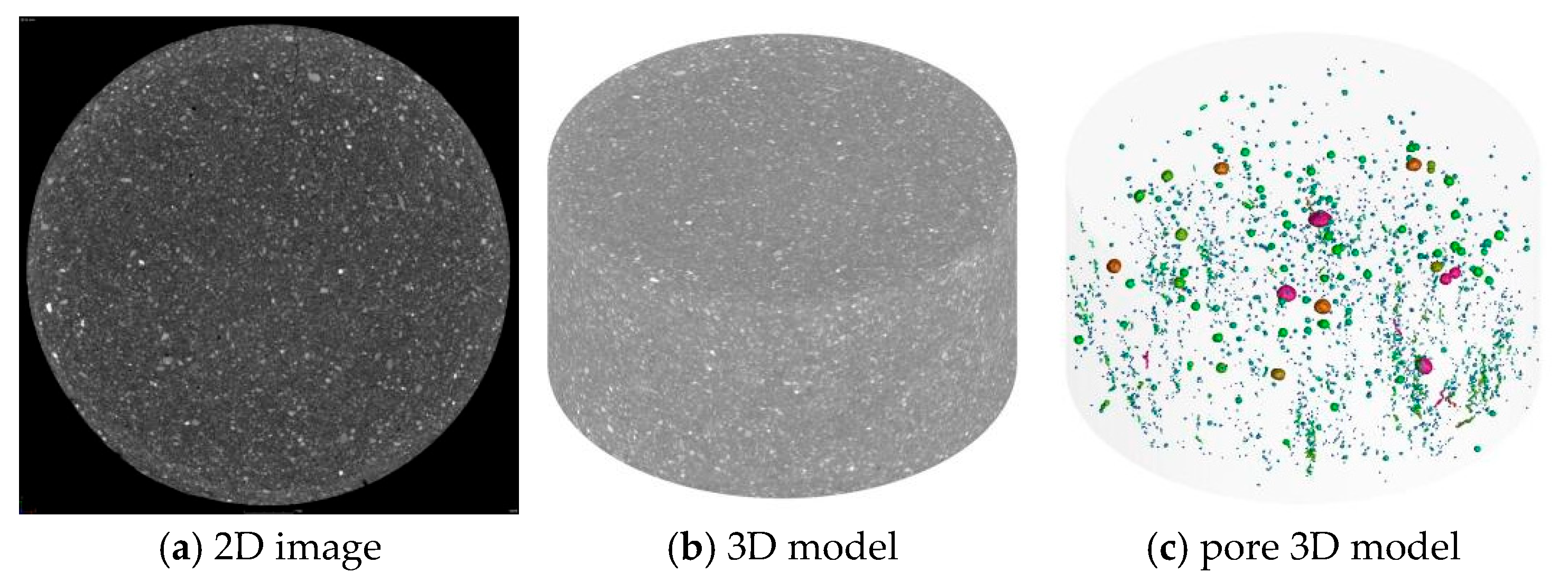
The internal microstructure of the impacted CTB specimens was examined using X-ray computed tomography (CT). The scanning was performed with a Nikon XT H 225 ST micro-CT system (Nikon, Shinagawa, Japan). The scanning parameters were set as follows: a voltage of 130 kV and a current of 150 μA. A total of 1000 axial slice projections were collected. The two-dimensional images of micro-CT scans can only show the distribution of pores and cracks in a particular slice, and they cannot visually represent the three-dimensional structure of the specimen. Therefore, it is necessary to convert a set of 2D CT data into 3D images to more intuitively visualise the internal microstructure of the CTB specimen. The CT images were reconstructed with a spatial resolution of 27.4 μm. The 3D reconstruction and quantitative analysis of pores and cracks were conducted using VG Studio MAX software. The key step in quantifying porosity is image segmentation, which distinguishes pores and cracks (the void phase) from the solid cement-tailings matrix. This was achieved through a global thresholding technique. The grayscale histogram of the CT data, which reflects the distribution of X-ray attenuation coefficients, typically exhibits a bimodal distribution where one peak corresponds to the pores (darker pixels) and the other to the solid material (brighter pixels). A specific grayscale threshold value was manually selected at the valley between these two peaks to binarize the images. All voxels with intensities below this threshold were classified as pores/cracks, while those above were classified as solid material. The selected threshold was consistently applied to all specimens to ensure comparability. Figure 5 presents the 3D reconstruction process of the CTB specimen. Firstly, 2D image data of the CTB specimen was acquired, as shown in Figure 5a. Then, the 3D reconstruction was obtained by superimposing the 2D image data. The 3D data were converted using an interpolation calculation method and the structural information was displayed as a 3D image as shown in Figure 5b. By combining the adjusted positional parameters with the reconstructed CTB model, the pore network was segmented and color-rendered as shown in Figure 5c [30,37].

3. Result and Discussion

3.1. Stress–Strain Characteristics

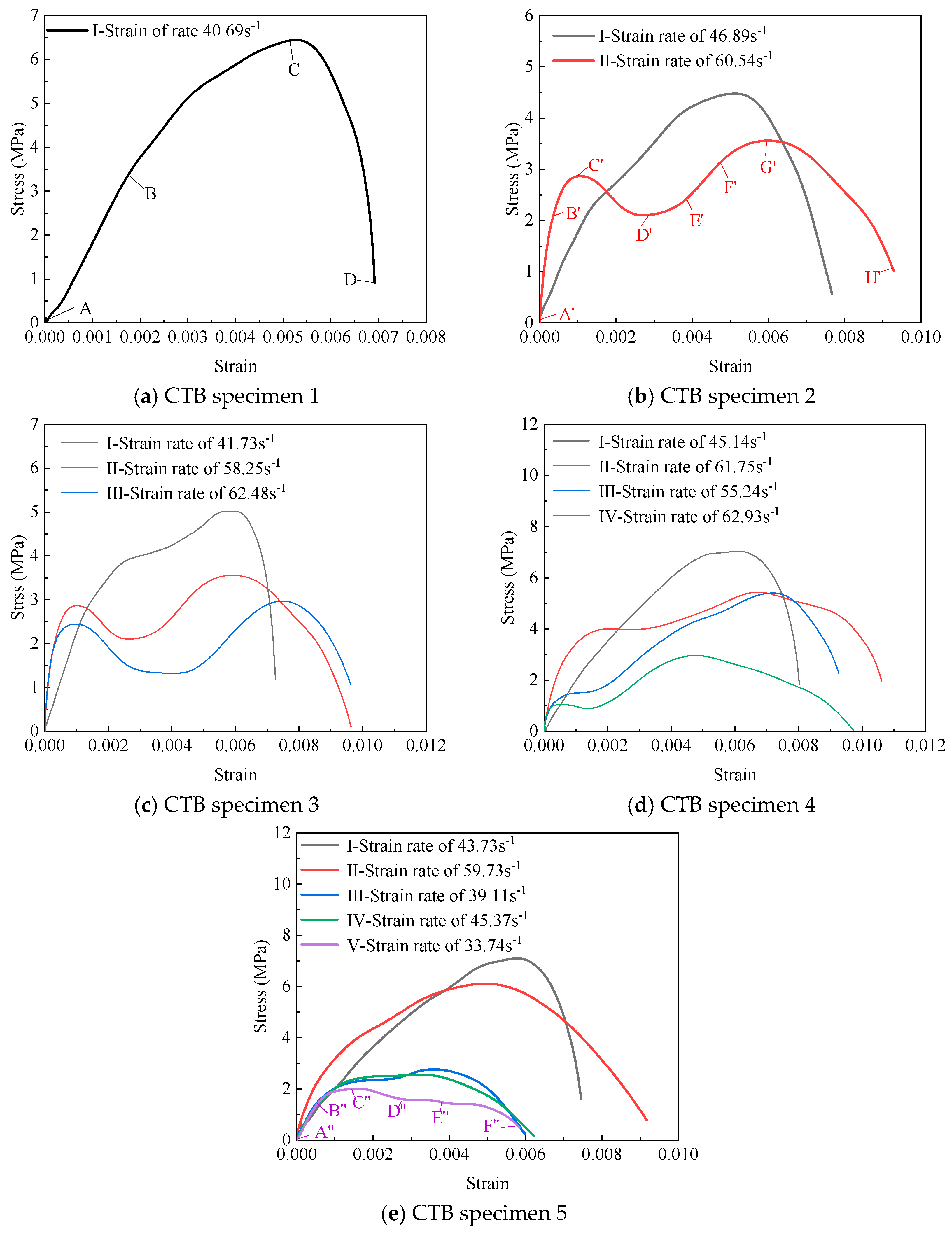
Figure 6 shows the stress–strain curves of CTB specimens under different numbers of impacts. When the strain rates are similar, the initial stages of the stress–strain curves for each impact coincide, indicating similar initial elastic moduli. However, as the strain rate increases, the initial elastic modulus increases. Under a single impact, the deformation of CTB specimens mainly undergoes three stages: elastic deformation (AB), inelastic deformation (BC), and crack penetration leading to destruction (CD) as shown in Figure 6a. The crack closure stage is not evident. Transient closure occurs upon impact; consequently, the stress–strain curve lacks a distinct crack closure phase initially and proceeds directly to the elastic deformation stage. Under multiple cyclic impacts, the deformation of CTB specimens mainly passes through stages such as crack closure, elastic deformation, inelastic deformation, crack penetration, and destruction. However, high and low strain rates produce different variations. When the strain rate is high, the CTB specimen undergoes stages of elastic deformation (A′B′), inelastic deformation (B′C′), crack extension (C′D′), crack closure (D′E′), elastic deformation (E′F′), inelastic deformation (F′G′), and crack penetration leading to damage (G′H′) as shown in Figure 6b. The stress–strain curve shows a bimodal pattern. This indicates that cyclic impact can cause compression and cracking, allowing the specimen to maintain a certain strength after crack compaction until final destruction. The reason that instantaneous crack closure does not occur during the D′E′ stage is that crack propagation continues during compaction. Even at the G′H′ stage, there is still the possibility of crack compaction in the undamaged part. This was investigated using CT to carry out mesoscopic analysis. When the strain rate is low, the CTB specimen undergoes stages of elastic deformation (A″B″), inelastic deformation (B″C″), crack extension (C″D″), crack closure (D″E″), and crack penetration leading to damage (E′F′) as shown in Figure 6e. However, the crack closure stage (D″E″) is not evident. Damage occurs after the CTB specimen has passed through the crack closure stage (D″E″) and does not maintain a certain strength. This may be attributed to a weakening strain rate effect.

3.2. Variation Characteristics of DPCS and Elastic Modulus

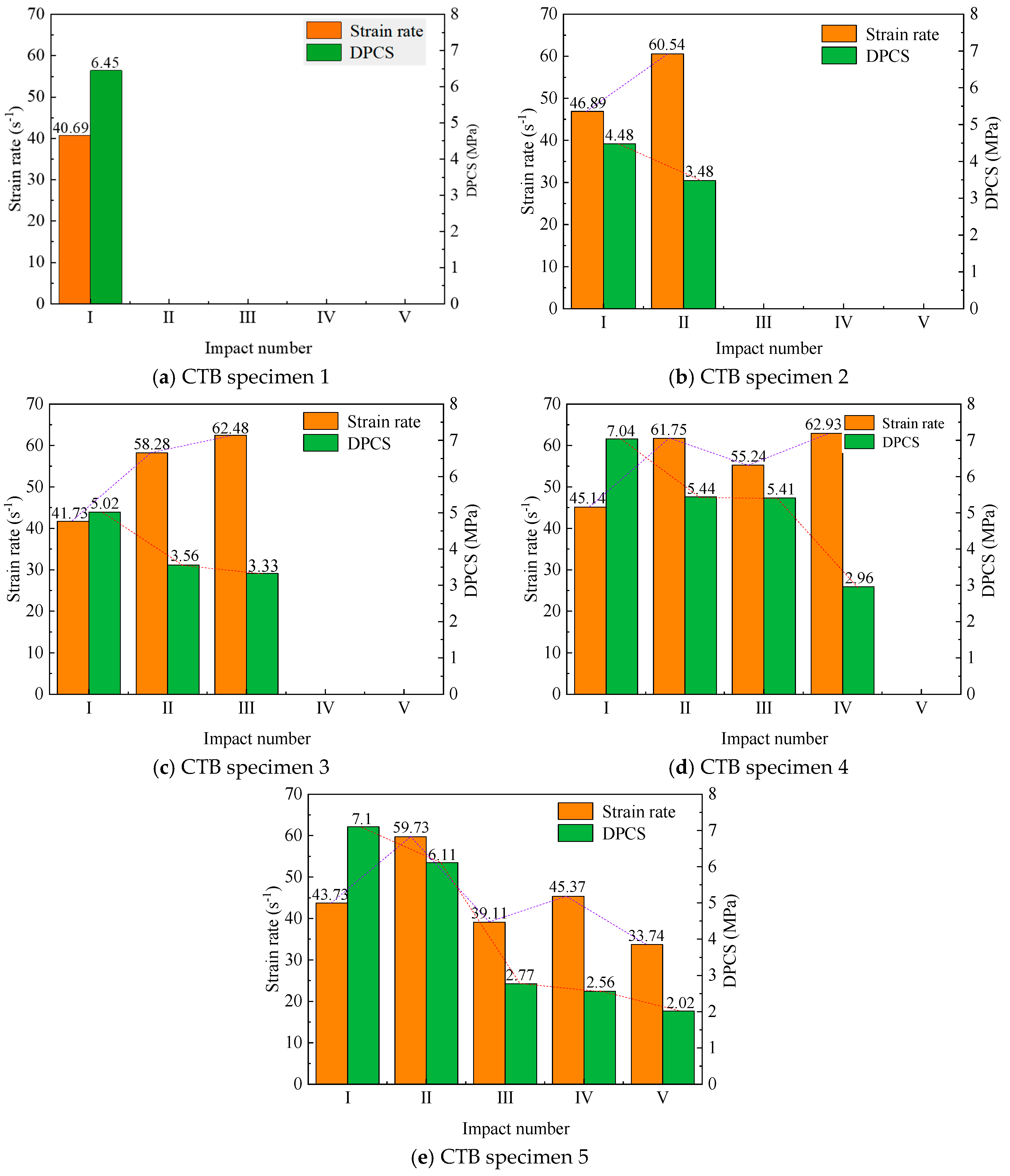
Figure 7 shows the relationship between strain rate, impact number, and DPCS. As can be seen from Figure 7, as the number of impacts increases, the DPCS of the CTB specimens gradually decreases. Although cyclic impacts can compact some cracks within the CTB specimens, new cracks initiate and propagate, leading to a reduction in DPCS. This indicates that impact damage to the CTB from mine blasting accumulates and reduces its strength. The strength of the CTB under cyclic impact exhibits a strain rate effect. In the case of an increasing strain rate, the DPCS of the CTB decreases by a smaller magnitude. For a decreasing strain rate, the DPCS of the CTB decreases by a larger amount. During mine blasting, the strain rate imposed on CTB can be modulated by controlling the blasting energy release, potentially enhancing its blast resistance.

3.3. Energy Evolution Characteristics

Table 1 presents the energy characterization of CTB under cyclic impacts. The energy reflectance and transmittance rates do not show a clear trend. The energy absorption rate decreases as the number of impacts increases. The absorbed energy is primarily consumed by crack propagation within the CTB. With the increase in the number of impacts, the extended cracks continue to accumulate and gradually form larger cracks. When the accumulated cracks are sufficiently large, less energy needs to be absorbed to cause damage to the CTB. This significantly threatens the stability of the CTB. Therefore, it is necessary to evaluate the cumulative damage of the CTB under the influence of blasting to ensure its stability.

3.4. Failure Modes

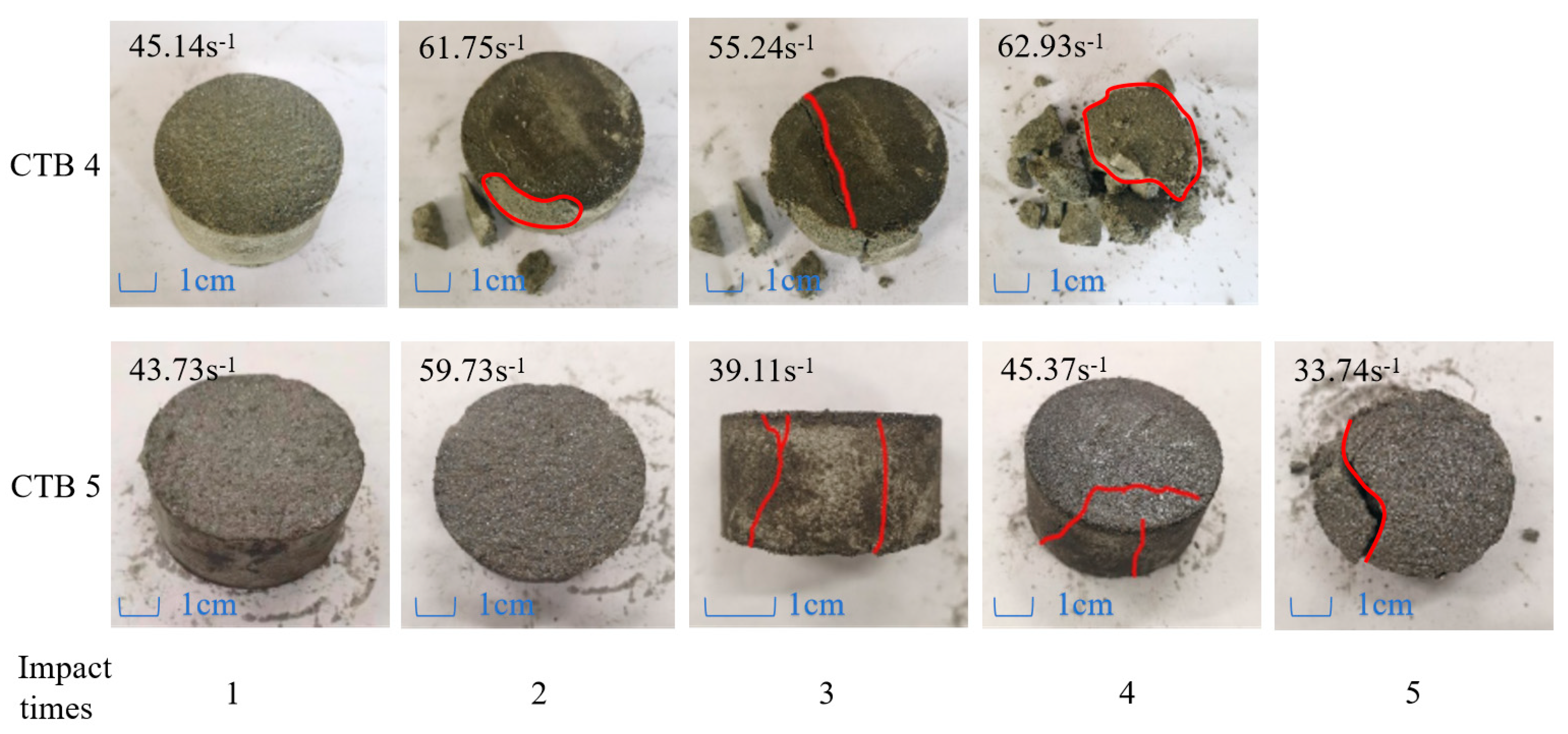
The failure modes are analyzed using the CTB specimens with 4 and 5 impacts as examples. The failure modes are shown in Figure 8. Both cyclic impact experiments result in complete damage during the last impact. The failure process typically involves: edge fracturing or crack initiation, followed by crack propagation, and finally specimen rupture. After the initial impact, the specimen does not exhibit macro-cracks. At this stage, internal microcracks are likely propagating and compacting pre-existing pores or cracks. Subsequent impacts compact existing microcracks or pores while simultaneously initiating and propagating new cracks, eventually forming macro-cracks. Macroscopic crack penetration leads to the final destruction of the CTB specimens. Although the strength reduction in the CTB specimens under high strain rate conditions is smaller, the final impact damage is much greater than that of the CTB specimens under low strain conditions. Crushing failure occurs at the edges of CTB specimens under high strain rates. In contrast, only splitting damage occurs in the CTB specimens at low strain rates. This indicates that high-intensity blasting produces greater damage to the backfill. The failure modes of CTB specimens subjected to single-impact and cyclic-impact tests exhibit differences. Cyclic impact is more likely to cause edge splitting failure in specimens. Single impact is more likely to result in overall failure and form a tapered cone [5].

3.5. Mesoscopic Characteristics

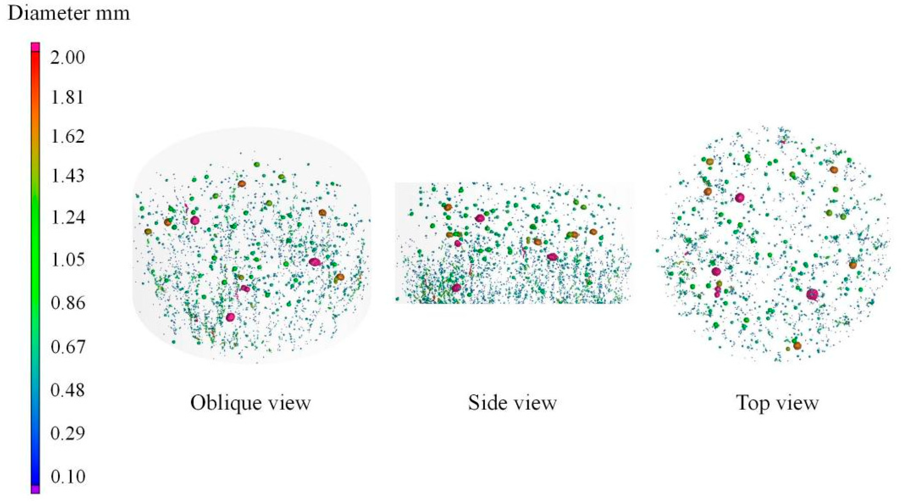
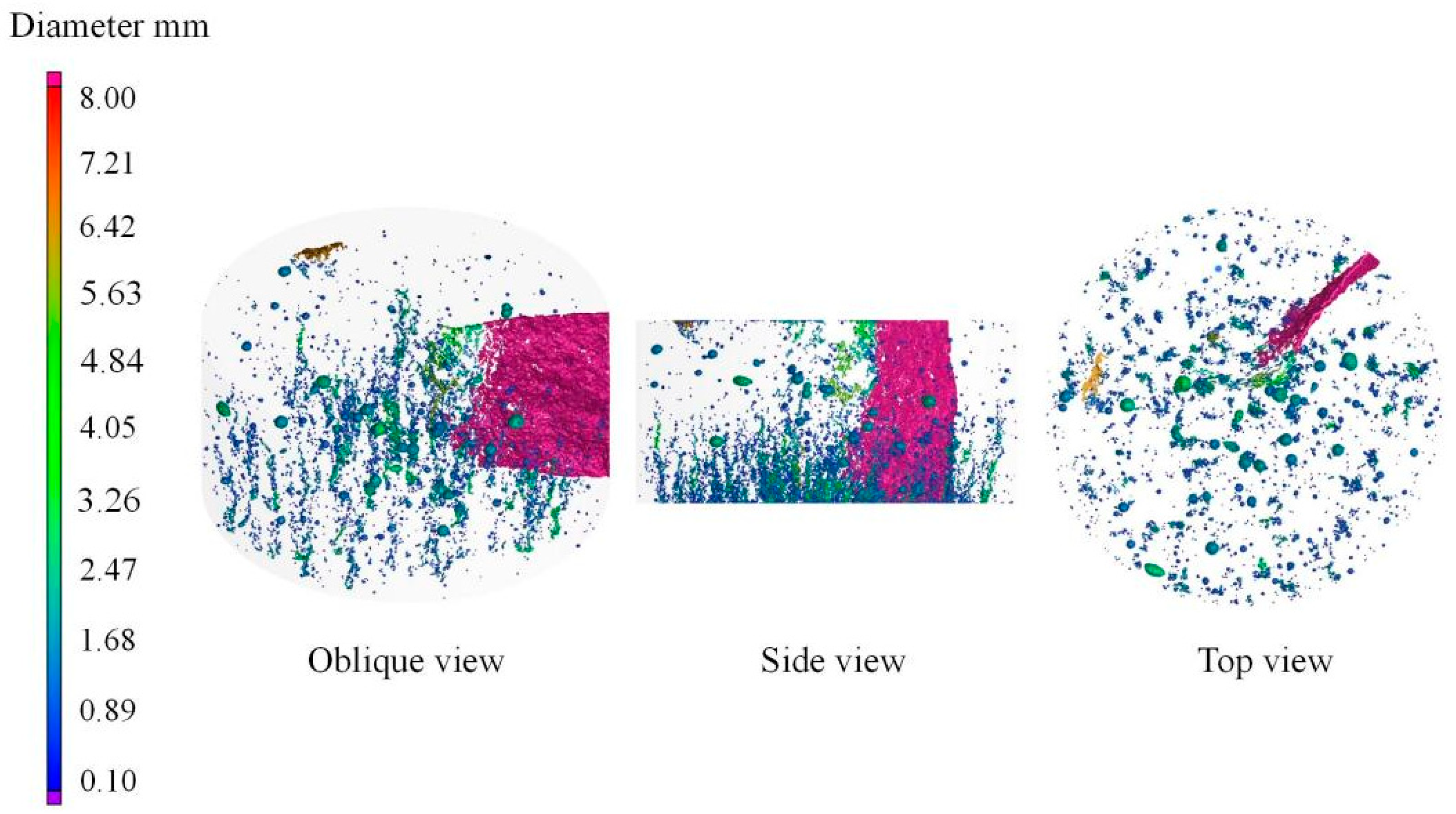
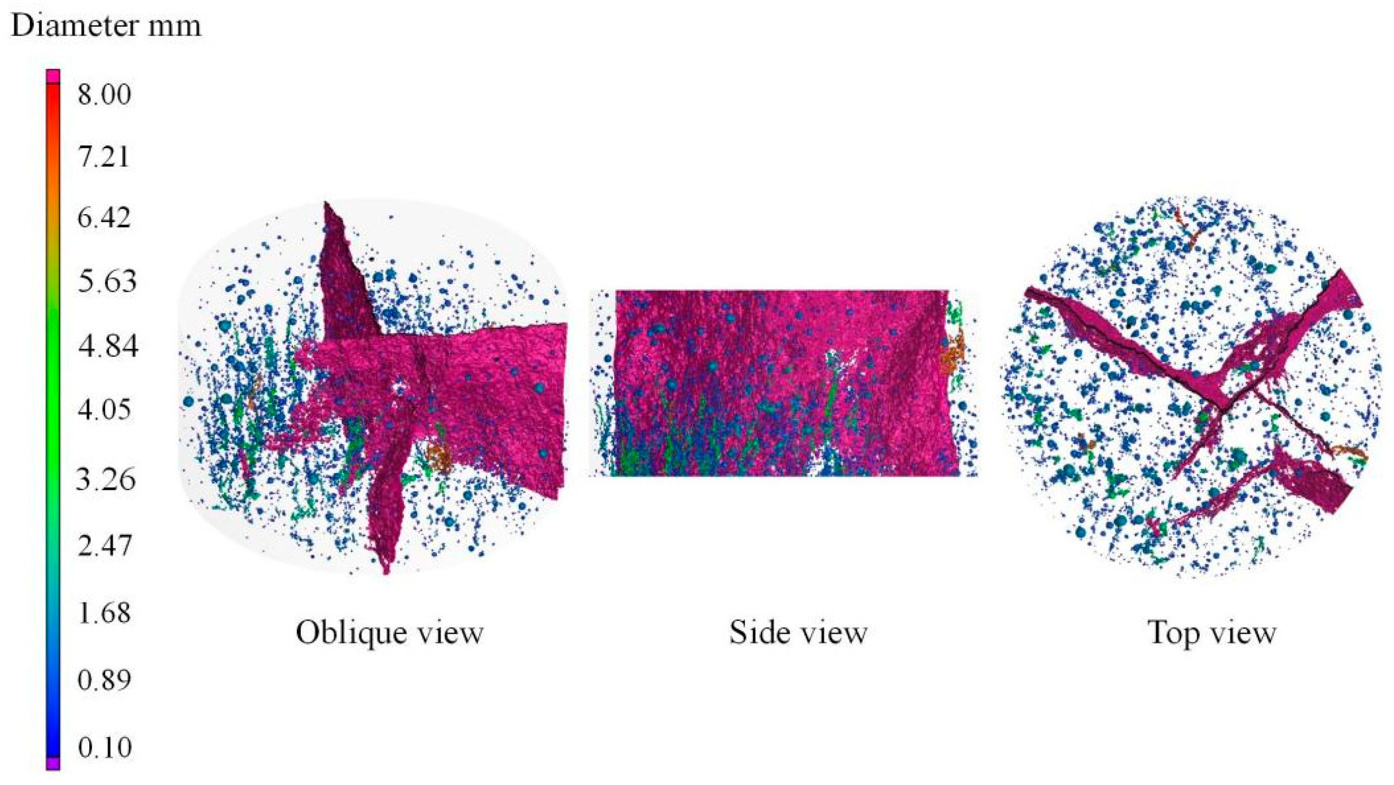
Figure 9, Figure 10 and Figure 11 show the spatial distribution of pores and cracks in CTB specimens with different numbers of impacts. The interior of the CTB specimen contains numerous spherical pores, resulting from entrapped air bubbles that were not eliminated during specimen preparation. These bubbles are relatively evenly distributed in the upper part of the specimen. Since the stress wave is incident from the bottom of the CTB specimen during impact, many small pores and microcracks are formed at the bottom of the specimen after the first impact. These small pores and microcracks are predominantly located at the specimen edges. They are mostly isolated at the bottom of the CTB specimen. After the second impact, the small isolated pores located at the bottom gradually increase and begin to interconnect. These connected pores appear as longitudinal strips. This phenomenon no longer occurs only at the edges of the specimen, but also in large numbers in the center of the specimen. A through crack is formed locally in the CTB specimen. After the third impact, the pores continue to connect, and the cracks continue to expand. Eventually, multiple connected cracks are formed, resulting in the final destruction of the specimen. The bubble structures do not serve as preferential pathways for crack propagation during impact. This indicates that the bubble structure in the CTB does not weaken its strength.
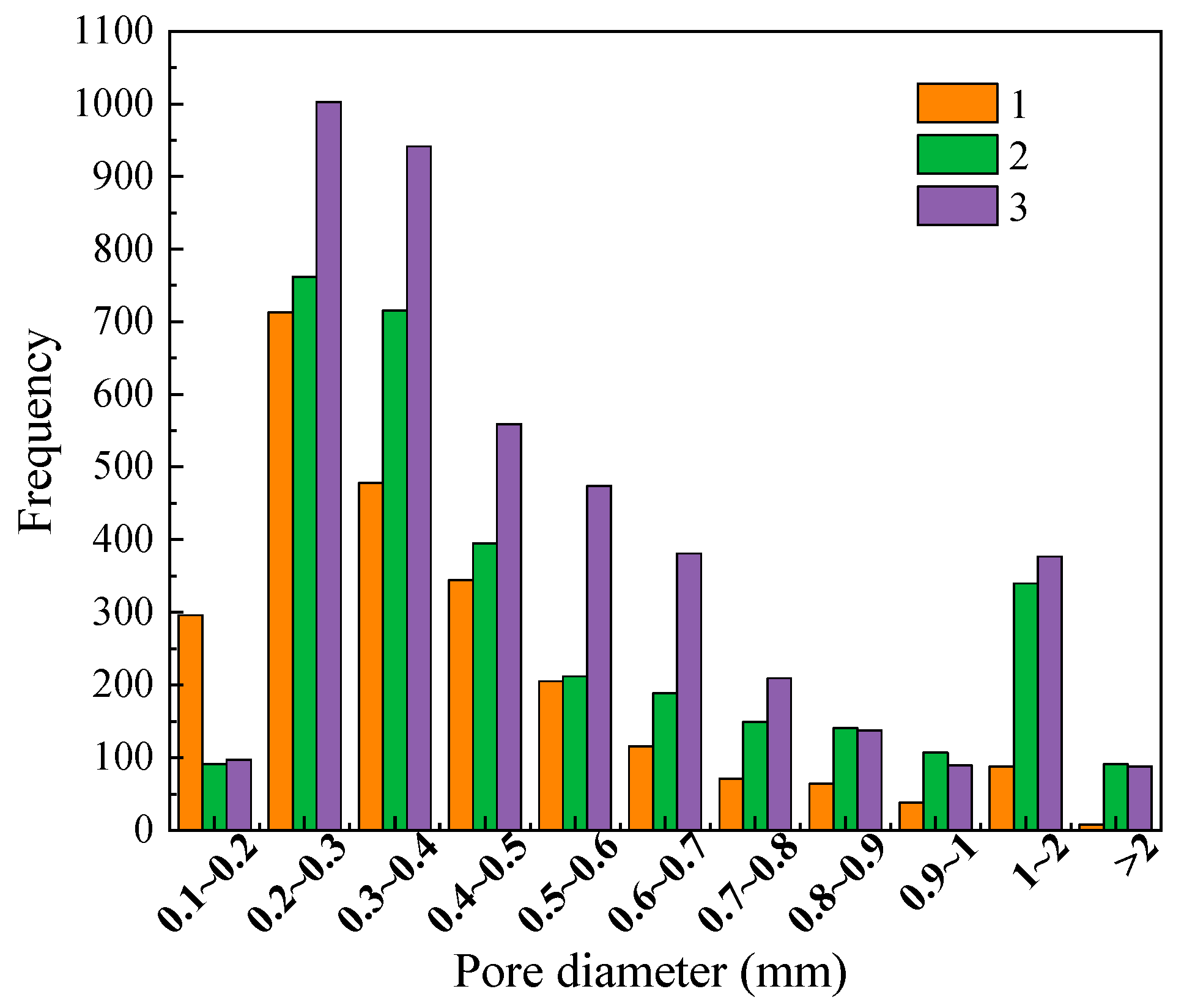
In the 3D pore reconstruction, each pore region was identified. A minimum bounding sphere that completely enclosed each pore was determined. The pore diameter was then calculated by measuring the sphere’s diameter using the measurement function in VG Studio MAX software. Finally, the pore diameters for each specimen were counted to analyze the distribution of pore sizes. Figure 12 shows the pore size distribution of CTB. As the number of impacts increases, the overall porosity of the specimen continues to rise, but the proportion of small pores (0.1–0.3 mm) decreases with each impact. For pore diameters greater than 0.6 mm, the porosity proportion either increases continuously or initially increases and then decreases with impact cycles. For pores within the 0.3–0.6 mm range, the porosity proportion first increases then decreases, or first decreases and then increases with impact cycles. This indicates that the relative proportions of large and small pores in the specimen changed after cyclic impact loading, with failure primarily attributed to the opening of cracks due to the increased proportion of large pores. Naturally, this relative change in pore size distribution is not exhaustive. Therefore, Figure 13 presents the frequency distribution of pore sizes. During the impact process, the small pores in the 0.1–0.2 mm range did indeed decrease due to compression.
This is the reason for the second peak in the stress–strain curve after the second and third impacts. This compaction of a portion of small pores or cracks also contributes to the apparent slowdown in the strength reduction rate during multiple impacts. The porosity increases, and the cracks inside the specimen are already undergoing expansion. Less energy is required for further pore or crack expansion, resulting in a decreasing energy absorption rate. The transverse pores or cracks are more likely to be compressed during impact, making them expand along the longitudinal direction. Therefore, the specimen eventually undergoes splitting failure. The compaction of these small pores or cracks enhances the local strength. Safari and Taheri’s research reached similar conclusions [33]. The difference lies in the loading sequence: Safari and Taheri applied dynamic load perturbations during static loading. This resulted in greater pore compression within the specimens, leading to a more pronounced strength enhancement. In contrast, this study directly applied dynamic loads, causing both pore compression and crack propagation to occur simultaneously. Consequently, no significant increase in strength was observed.

4. Conclusions

(1)
Cyclic dynamic loading significantly degrades the mechanical properties of CTB. As the number of impacts increases, the dynamic peak compressive strength (DPCS) exhibits a consistent decline. This reduction is attributed to the accumulation of internal damage through the initiation and propagation of microcracks. Although partial crack compaction occurs during cyclic loading, it is insufficient to counteract the overall damage accumulation. The strain rate also plays a critical role: higher strain rates result in a slower decline in DPCS, suggesting that controlled blasting energy release could mitigate strength loss. These findings underscore the importance of considering cumulative damage in the design and assessment of backfill structures subjected to repeated dynamic disturbances.
(2)
Energy absorption capacity decreases with increasing impact cycles, reflecting internal damage evolution. The energy absorption rate of CTB specimens declines progressively under cyclic impacts, indicating reduced capacity to dissipate energy through microcrack formation and propagation. The absorbed energy is primarily consumed by crack expansion and coalescence, leading to a decrease in overall structural integrity. As damage accumulates, less energy is required to cause failure, highlighting the vulnerability of CTB under repeated loading. This energy-based analysis provides a valuable perspective for evaluating the long-term stability and failure thresholds of backfill materials in dynamic mining environments.
(3)
Mesoscopic characteristics reveal the evolution of internal damage under cyclic loading. CT scans and 3D reconstructions show that cyclic impacts cause microcracks to initiate predominantly at the specimen edges and gradually propagate and interconnect, forming macroscopic fracture networks. Pore size distribution analysis indicates that large pores increase with impact cycles, while small pores decrease due to compaction. This mesoscopic behavior explains the macroscopic mechanical response, including the bimodal stress–strain curves observed under high strain rates. The study demonstrates that mesostructural analysis is essential for understanding the damage mechanisms and improving the durability of CTB under cyclic dynamic loads.
(4)
This study has some limitations. Future work should focus on refining the experimental apparatus to achieve consistently lower strain rates, enabling the investigation of CTB’s dynamic properties and mesoscopic characteristics under such conditions.

Author Contributions

Conceptualization, R.Y. and X.Y.; methodology, J.C. and Y.Z. (Yunpeng Zhang); validation, X.Y. and C.L.; formal analysis, J.C. and R.Y.; investigation, Y.Z. (Yuxi Zhang); resources, Z.L. and X.Y.; writing—original draft preparation, R.Y. and X.Y.; writing—review and editing, Y.Z. (Yunpeng Zhang); funding acquisition, Z.L. and X.Y. All authors have read and agreed to the published version of the manuscript.

Funding

This research was funded by the Science and Technology Research Project of Hebei University (No. QN2023166), the Natural Science Foundation of Hebei Province (No. E2024209141) and the National Natural Science Foundation of China (No. 52204134).

Data Availability Statement

The data presented in this study are available on request from the corresponding author. The data contain confidential information which cannot be publicly disclosed.

Conflicts of Interest

The authors declare no conflicts of interest.

References

  1. Safari, A.; Tennant, C.; Gholampour, A.; Palmer, J.; Taheri, A. Effect of mixing water temperature on the thermal and microstructural evolution of cemented paste backfill in underground mining. Minerals 2025, 15, 887. [Google Scholar] [CrossRef]
  2. Li, J.X.; Sun, W.; Li, Q.Q.; Chen, S.; Yuan, M.L.; Xia, H. Influence of layered angle on dynamic characteristics of backfill under impact loading. Minerals 2022, 12, 511. [Google Scholar] [CrossRef]
  3. Wu, A.X.; Ruan, Z.E.; Wang, J.D. Rheological behavior of paste in metal mines. Int. J. Miner. Metall. Mater. 2022, 29, 717–726. [Google Scholar] [CrossRef]
  4. Zhang, N.; Yuan, L.; Han, C.; Xue, J.; Kan, J. Stability and deformation of surrounding rock in pillarless gob-side entry retaining. Saf. Sci. 2012, 50, 593–599. [Google Scholar] [CrossRef]
  5. Zou, S.Z.; Guo, W.H.; Wang, S.; Gao, Y.T.; Qian, L.Y.; Zhou, Y. Investigation of the dynamic mechanical properties and damage mechanisms of fiberreinforced cemented tailing backfill under triaxial split-Hopkinson pressure bar testing. J. Mater. Res. Technol. 2023, 27, 105–121. [Google Scholar] [CrossRef]
  6. Yu, H.; Zahidi, I. Spatial and temporal variation of vegetation cover in the main mining area of Qibaoshan Town, China:potential impacts from mining damage, solid waste discharge and land reclamation. Sci. Total Environ. 2023, 859, 160392. [Google Scholar] [CrossRef]
  7. Pappu, A.; Saxena, M.; Asolekar, S.R. Solid wastes generation in India and their recycling potential in building materials. Build. Environ. 2007, 42, 2311–2320. [Google Scholar] [CrossRef]
  8. Wang, J.D.; Jiang, G.; Wu, A.; Wang, Y.; Yin, S.; Wang, Y. Rheological behavior of a novel quick-setting binder under resting and mixing and its relations to hydration and microstructure. Constr. Build. Mater. 2022, 357, 129313. [Google Scholar] [CrossRef]
  9. Gao, T.; Sun, W.; Li, Z.Y.; Fan, K.; Jiang, M.G.; Cheng, H.Y. Study on shear characteristics and failure mechanism of inclined layered backfill in mining solid waste utilization. Minerals 2022, 12, 1540. [Google Scholar] [CrossRef]
  10. Hou, Y.Q.; Yin, S.H.; Yang, S.X.; Chen, X.; Du, H.H. Mechanical properties, damage evolution and energy dissipation of cemented tailings backfill under impact loading. J. Build. Eng. 2023, 66, 105912. [Google Scholar] [CrossRef]
  11. Song, B.F.; Li, H.Y.; An, R.; Zhang, X.W.; Zhou, Z.F. Experimental study on the strength and damage characteristics of cement–fly ash–slag–gangue cemented backfill. Buildings 2024, 14, 1411. [Google Scholar] [CrossRef]
  12. Kalisz, S.; Kibort, K.; Mioduska, J.; Lieder, M.; Malachowska, A. Waste management in the mining industry of metals ores, coal, oil and natural gas—A review. J. Environ. Manag. 2022, 304, 114239. [Google Scholar] [CrossRef]
  13. Chen, X.; Shi, X.; Zhou, J.; Li, E.; Qiu, P.; Gou, Y. High strain rate compressive strength behavior of cemented paste backfill using split Hopkinson pressure bar. Int. J. Mining Sci. Technol. 2021, 31, 387–399. [Google Scholar] [CrossRef]
  14. Tan, Y.Y.; Davide, E.; Zhou, Y.C.; Song, W.D.; Meng, X. Long-term mechanical behavior and characteristics of cemented tailings backfill through impact loading. Int. J. Miner. Metall. Mater. 2020, 27, 140–151. [Google Scholar] [CrossRef]
  15. Liu, Z.Y.; Gan, D.Q.; Gan, Z. Dynamic regimes of cemented backfill at early-age. J. Cent. South Univ. 2021, 28, 2079–2090. [Google Scholar] [CrossRef]
  16. Tan, Y.Y.; Yu, X.; Elmo, D.; Xu, L.H.; Song, W.D. Experimental study on dynamic mechanical property of cemented tailings backfill under SHPB impact loading. Int. J. Miner. Metall. Mater. 2019, 26, 404–416. [Google Scholar] [CrossRef]
  17. Lyu, H.Y.; Chen, Y.L.; Pu, H.; Ju, F.; Zhang, K.; Li, Q.; Wu, P. Dynamic properties and fragmentation mechanism of cemented tailings backfill with various particle size distributions of aggregates. Constr. Build. Mater. 2023, 366, 130084. [Google Scholar] [CrossRef]
  18. Cao, S.; Yilmaz, E.; Song, W.D. Dynamic response of cement-tailings matrix composites under SHPB compression load. Constr. Build. Mater. 2018, 186, 892–903. [Google Scholar] [CrossRef]
  19. Zhang, Y.H.; Wang, X.M.; Wei, C.; Zhang, Q. Dynamic mechanical properties and instability behavior of layered backfill under intermediate strain rates. Trans. Nonferrous Met. Soc. Chin. 2017, 27, 1608–1617. [Google Scholar] [CrossRef]
  20. Han, L.; Liu, J.X. Experimental study on mechanical properties of cemented backfill under dynamic loading. Eng. Blast. 2021, 27, 35–41. [Google Scholar]
  21. Wu, Z.K.; Jin, A.B.; Chen, S.J. Study on cemented tailing backfill dynamic characteristics and its blasting response simulation. Met. Mine 2020, 7, 25–32. [Google Scholar]
  22. Li, J.; Cao, S.; Yilmaz, E.; Liu, Y. Compressive fatigue behavior and failure evolution of additive fiber-reinforced cemented tailings composites. Int. J. Miner. Metall. Mater. 2022, 29, 345–355. [Google Scholar] [CrossRef]
  23. Huang, Z.; Cao, S.; Yilmaz, E. Investigation on the flexural strength, failure pattern and microstructural characteristics of combined fibers reinforced cemented tailings backfill. Constr. Build. Mater. 2021, 300, 124005. [Google Scholar] [CrossRef]
  24. Libos, I.L.S.; Cui, L.; Liu, X. Effect of curing temperature on time-dependent shear behavior and properties of polypropylene fiber-reinforced cemented paste backfill. Constr. Build. Mater. 2021, 311, 125302. [Google Scholar] [CrossRef]
  25. Jia, H.; Yan, B.; Yilmaz, E.; Chen, Q. A large goaf group treatment by means of mine backfill technology. Adv. Civ. Eng. 2021, 2021, 3737145. [Google Scholar] [CrossRef]
  26. Song, X.P.; Hao, Y.X.; Wang, S.; Zhang, L.; Liu, H.B.; Yong, F.W.; Dong, Z.L.; Yuan, Q. Dynamic mechanical response and damage evolution of cemented tailings backfill with alkalized rice straw under SHPB cycle impact load. Constr. Build. Mater. 2022, 327, 127009. [Google Scholar] [CrossRef]
  27. Tan, Y.; Wang, J.; Song, W.; Xu, L.; Cao, S. Experimental study on mechanical properties of cemented tailings backfill under cycle dynamic loading test. J. Min. Saf. Eng. 2019, 36, 184–192. [Google Scholar]
  28. Shu, R.H.; Xu, G.; Huang, L.J.H. Dynamic compressive properties of heat-treated and pre-stressed cement mortar specimen subjected to cyclic impact loading. Case Stud. Therm. Eng. 2024, 57, 104362. [Google Scholar] [CrossRef]
  29. Liao, H.; Fang, Y.; Yao, Z.G.; Yu, T.; Luo, H.; Zhu, N.B.; Wang, Y.H.; Li, M.K. Effects of fiber and rubber materials on the dynamic mechanical behaviors and damage evolution of shotcrete under cyclic impact load. J. Build. Eng. 2023, 73, 106763. [Google Scholar] [CrossRef]
  30. Zheng, D.; Song, W.D.; Cao, S.; Li, J.J. Dynamical mechanical properties and microstructure characteristics of cemented tailings backfill considering coupled strain rates and confining pressures effects. Constr. Build. Mater. 2022, 320, 126321. [Google Scholar] [CrossRef]
  31. Cao, S.; Xue, G.; Yilmaz, E.; Yin, Z.; Yang, F. Utilizing concrete pillars as an environmental mining practice in underground mines. J. Clean. Prod. 2021, 278, 123433. [Google Scholar] [CrossRef]
  32. Cao, S.; Yilmaz, E.; Yin, Z.; Xue, G.; Song, W.; Sun, L. CT scanning of internal crack mechanism and strength behavior of cement-fiber-tailings matrix composites. Cem. Concr. Compos. 2021, 116, 103865. [Google Scholar] [CrossRef]
  33. Safari, A.; Taheri, A.; Karakus, M. Mechanical and microstructural behavior of cemented paste backfill under cyclic loading. Minerals 2025, 15, 123. [Google Scholar] [CrossRef]
  34. Liu, W.Z.; Guo, Z.P.; Wang, C.; Niu, S.W. Physico-mechanical and microstructure properties of cemented coal Gangue-Fly ash backfill effects of curing temperature. Construct. Build. Mater. 2021, 299, 124011. [Google Scholar] [CrossRef]
  35. Wang, D.L.; Na, Q.; Liu, Y.K.; Feng, Y.; Zhang, Q.L.; Chen, Q.S. Hydration process and fluoride solidification mechanism of multi-source solid waste-based phosphogypsum cemented paste backfill under CaO modification. Cement Concr. Comp. 2024, 154, 105804. [Google Scholar] [CrossRef]
  36. Dai, F.; Huang, S.; Xia, K.W.; Tan, Z.Y. Some fundamental issues in dynamic compression and tension tests of rocks using split Hopkinson pressure bar. Rock Mech. Rock Eng. 2010, 43, 657. [Google Scholar] [CrossRef]
  37. Liu, W.; Wang, G.; Han, D.; Xu, H.; Chu, X. Accurate characterization of coal pore and fissure structure based on CT 3D reconstruction and NMR. J. Nat. Gas Sci. Eng. 2021, 96, 104242. [Google Scholar] [CrossRef]
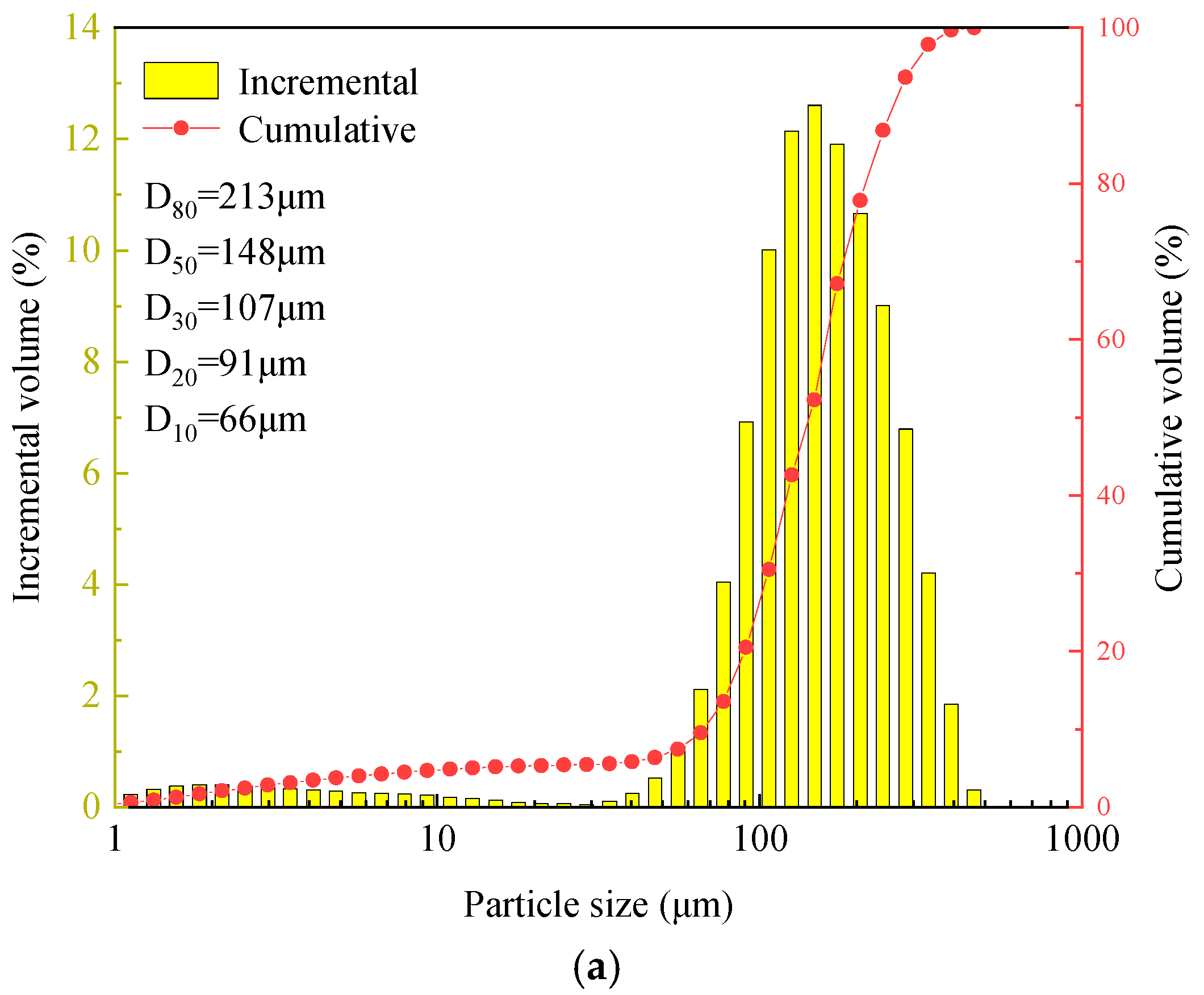
Figure 1. The tailings used in the test: (a) tailings particle size distribution, and (b) chemical composition of tailings.
Minerals 15 01140 g001aMinerals 15 01140 g001b
Figure 2. Tailings sample’s particle morphology.
Minerals 15 01140 g002
Figure 3. Preparation process of CTB specimens.
Minerals 15 01140 g003
Figure 4. Diagram of SHPB test.
Minerals 15 01140 g004
Figure 5. CTB 3D reconstruction process.
Minerals 15 01140 g005
Figure 6. Stress–strain curves of CTB specimens under different number of impacts.
Minerals 15 01140 g006
Figure 7. The relationship between strain rate and impact number and DPCS.
Minerals 15 01140 g007
Figure 8. Failure evolution process of CTB under cyclic impact.
Minerals 15 01140 g008
Figure 9. The crack and pore of CTB with 1 impact.
Minerals 15 01140 g009
Figure 10. The crack and pore of CTB with 2 impacts.
Minerals 15 01140 g010
Figure 11. The crack and pore of CTB with 3 impacts.
Minerals 15 01140 g011
Figure 12. Pore size distribution of CTB.
Minerals 15 01140 g012
Figure 13. Frequency distribution chart of pore diameters.
Minerals 15 01140 g013
Table 1. Energy characterization of CTB under cyclic impacts.
CTB NumberEnergy Reflectance Rate (%)Energy Transmittance Rate (%)Energy Absorption Rate (%)
1-170.282.4327.29
2-169.740.2829.98
2-273.710.8325.46
3-169.311.0429.65
3-275.971.5722.46
3-377.990.9121.1
4-164.521.5233.96
4-273.840.9825.18
4-384.230.3915.38
4-481.740.517.76
5-159.971.2538.78
5-272.010.2127.78
5-379.590.1820.23
5-481.850.1218.03
5-577.21.1421.66
Disclaimer/Publisher’s Note: The statements, opinions and data contained in all publications are solely those of the individual author(s) and contributor(s) and not of MDPI and/or the editor(s). MDPI and/or the editor(s) disclaim responsibility for any injury to people or property resulting from any ideas, methods, instructions or products referred to in the content.