1. Introduction
Crushing is an important mineral production process; together with grinding mills, this equipment accounts for more than half of the total capital investment for a typical mining operation [
1]. As a key comminution asset, the performance of the primary crusher directly impacts the downstream grinding circuit performance [
2,
3]. Great variabilities in crusher operating conditions, including ore (composition, hardness, particle size), liner designs and material selections, and operating parameters (power and feed levels) greatly affect its processing capacity [
4,
5]. Hence, accurate modelling for continuous improvement of the primary crusher’s performance is a key step for the overall comminution circuit optimisation.
In large throughput, open-pit mining operations, gyratory crushers are typically used in the primary crushing stage [
6,
7]. As shown in
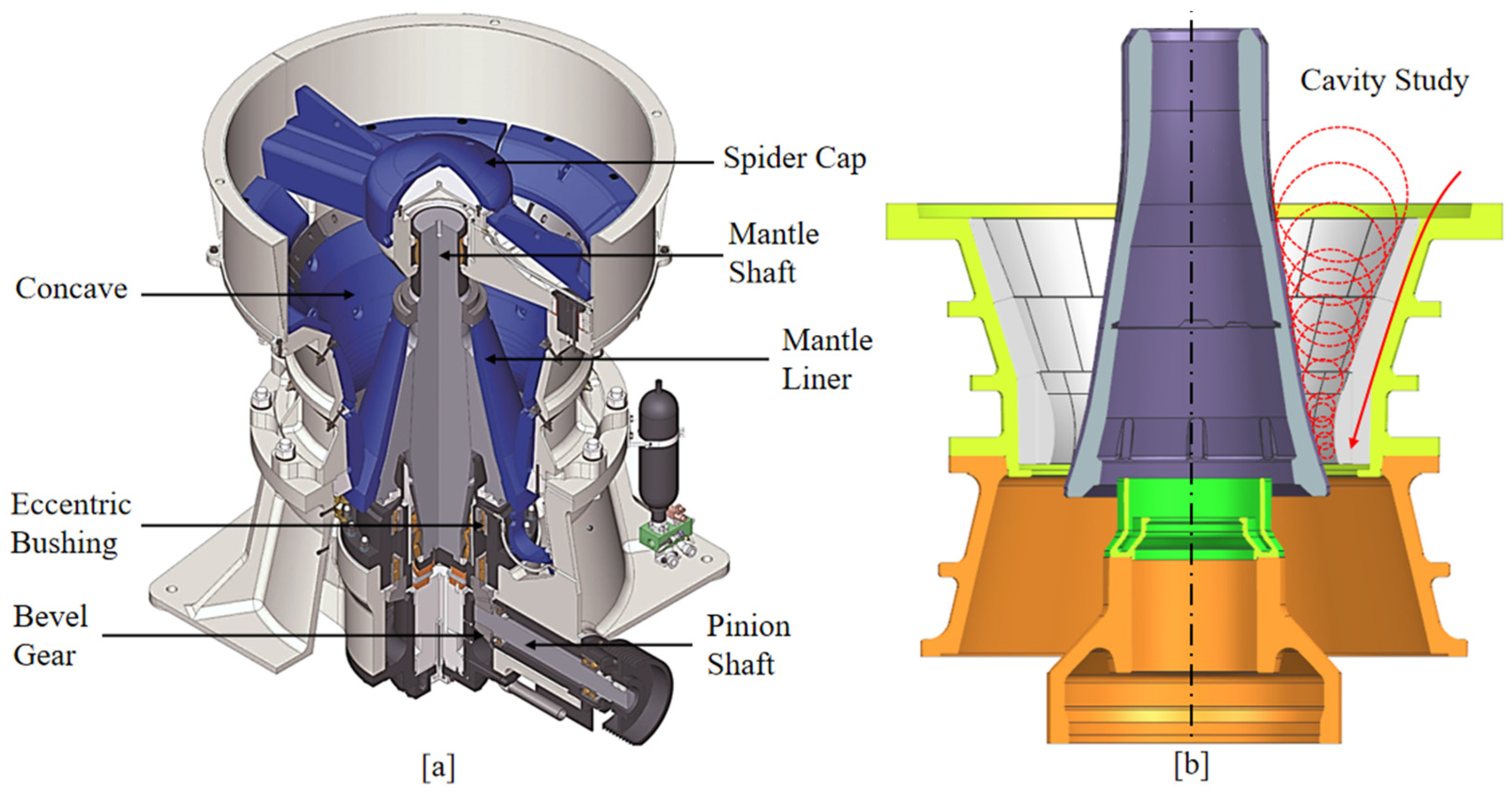
Figure 1a, the main shaft is driven by the eccentric gear train, and with a gyrating motion (oscillate in a small circular path) is induced to its lower end. The mantle component gyrates within the crushing chamber, progressively approaching and receding from the outer concave surface [
8]. When the material is fed into the crusher chamber, the rock particle size is progressively reduced until fully discharged out of the crusher. When over-sized or harder ores enter the crusher chamber, the mantle could be choked once its power surpasses the drive limit, which occurs on a regular basis if the operation of the crusher is not optimised. Therefore, when improving the performance of the gyratory crusher, it is vital to consider both the rock-structure and the drivetrain’s responses when modelling the gyratory crusher.
Empirical modelling has been used extensively to study the size reduction of a single particle in the crusher chamber, from which optimised designs of concave and mantle profiles were achieved by eliminating potential choke/blockage points and reducing localised wear [
9]. As shown in
Figure 1b, a series of circles which are tangential to both concave and mantle surfaces at a given level was generated by considering the mantle’s motion and the concave profile [
10]. Sufficient displacement of particles towards the discharge position is required to account for the volumetric expansion after crushing [
11]. Nevertheless, such a method obviously neglected the non-sphericity, ore hardness, and drivetrain response, which are critical for accurate reflection of the crusher operations [
12].
Recent advancement in numerical modelling, such as discrete element modelling (DEM), has enabled direct analysis of rock flow and interactions with the crusher structures [
13,
14]. Non-spherical particle shapes, such as Superquadrics and polyhedron, have also been further developed to complement the DEM modelling capabilities [
15]. Particle breakage models [
16,
17,
18,
19,
20] were also developed to analyse the size reduction behaviours of rocks, and associated force/torque induced onto the crusher concave and mantle, from which potential choke positions [
13], wear on liner surfaces [
21], and power output [
22] can all be estimated. Nevertheless, particle shape and breakage implementations have significantly decreased computational efficiency in industrial-scale gyratory crusher modelling. To resolve this, Graphics Processing Unit (GPU)-based DEM has rapidly been developed and applied in handling the large number of particles involved in complex granular systems [
23,
24,
25].
Moreover, the transient loading from rocks to the mantle also plays a significant role in the kinematic response of the mantle and the eccentric drive. In DEM-only modelling conditions, the mantle motion was commonly set to a fixed oscillating-rotational type, which considers no contact force feedback from the rock. Hence, particulate motion in the DEM phase requires additional drivetrain information provided by the multibody dynamics (MBD) to ensure both the rock and the machinery operating performance are accounted for [
26,
27,
28,
29]. Recent advancement of the functional mock-up interface (FMI)-based [
30] cosimulation methodology has also allowed different numerical modelling tools to communicate through interfaces (with internal models binding to each other) during simulation so that both programs can run at close to their best stand-alone speed.
Figure 1.
Schematic of the gyratory crusher system; (
a) major mechanical component; (
b) typical cavity study for optimising the concave and mantle profiles for gyratory crushers [
31].
Figure 1.
Schematic of the gyratory crusher system; (
a) major mechanical component; (
b) typical cavity study for optimising the concave and mantle profiles for gyratory crushers [
31].
Based on the aforementioned comments, this study aims to establish a cosimulation framework of multibody dynamics (MBD) and the discrete element method (DEM) to analyse the full performance of a gyratory crusher. An MBD model is to be initially established to simulate the gyratory crusher’s mechanical drive system. A GPU-based DEM method is also to be utilised for modelling the ore stream, and a parallel bond model is also to be included with particle breakage behaviour. Moreover, a Function Mock-up Interface (FMI)-based cosimulation framework of MBD and DEM is to be established under the Modelica standard environment. An industrial-scale gyratory crusher is to be selected for testing the developed numerical framework.
2. Multibody Dynamics Modelling
Multibody dynamics (MBD) has been extensively used in modelling kinematic functions of complex physical systems, including in mechanical, aeronautical, robotics, and structural engineering fields. Both commercial and open source MBD frameworks are available, such as SimulationX [
32], ADAMS, and Dymola [
33], and open source MBDyn and OpenModelica [
34].
In an MBD system, there are two critical components, the degree of freedom (DOF) and conditions of constraint. The DOF is the total number of independent parameters which define the spatial movement possibilities of an object (rigid body or soft body). Generally, an object has six degrees of freedom in a Cartesian coordinate, in which three are in translational motions and the other three are in rotational motions. Conditions of constraint define the motion restrictions applied to one or more objects in an MBD system. In this study, the MBD model was constructed in Modelica standard [
35,
36], which is a freely available, object-oriented language for modelling large, complex, and heterogeneous physical systems. The MBD model was established in commercial software Dymola.
In a gyratory crusher’s drive system, an eccentric shaft is rotated by a gear and pinion system which produces the oscillating rotational motion of the mantle. The mechanical system of the drive is composed of two major sub-components: a fixed spider frame on the top and a moving mantle and associated drivetrain. The mantle may also be lifted vertically to control the size of the crushed product when excessive liner wear occurs on concave or mantle liners. The drivetrain includes a gear, a pinion, and an electric motor which powers the entire system.
An industrial gyratory crusher (Nordberg Superior MKII 62–75) was selected in this study and its drivetrain was modelled using the Modelica standard.
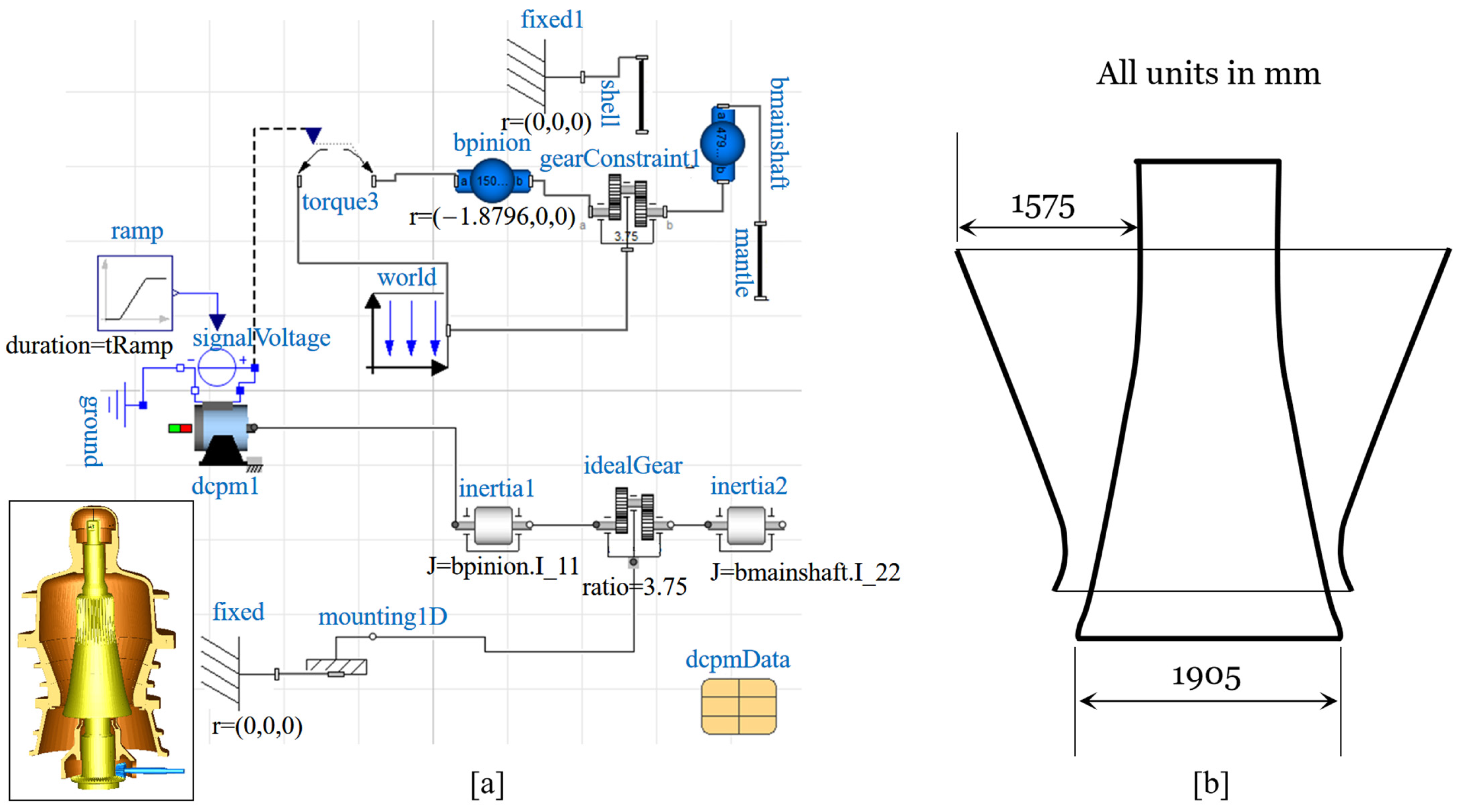
Figure 2a shows the Modelica diagram of the MBD system for the selected crusher. An induction motor supplying the crusher power was initially added with a voltage signal input. The motor was then connected to a set of gear and pinion with the nominated ratio of 3.75 per the manufacturer’s specification [
8]. The gear and pinion set was then connected to the eccentric shaft to induce the rotational-oscillatory motion. Within MBD, transient parameters of the drivetrain sub-components were monitored and exported during the simulation. The drivetrain model of the selected crusher modelled in MBD is shown in
Figure 2a with the mantle, eccentric shaft, gear, and pinion. Major dimensions of the selected crusher in terms of the feed opening and mantle diameter are shown in
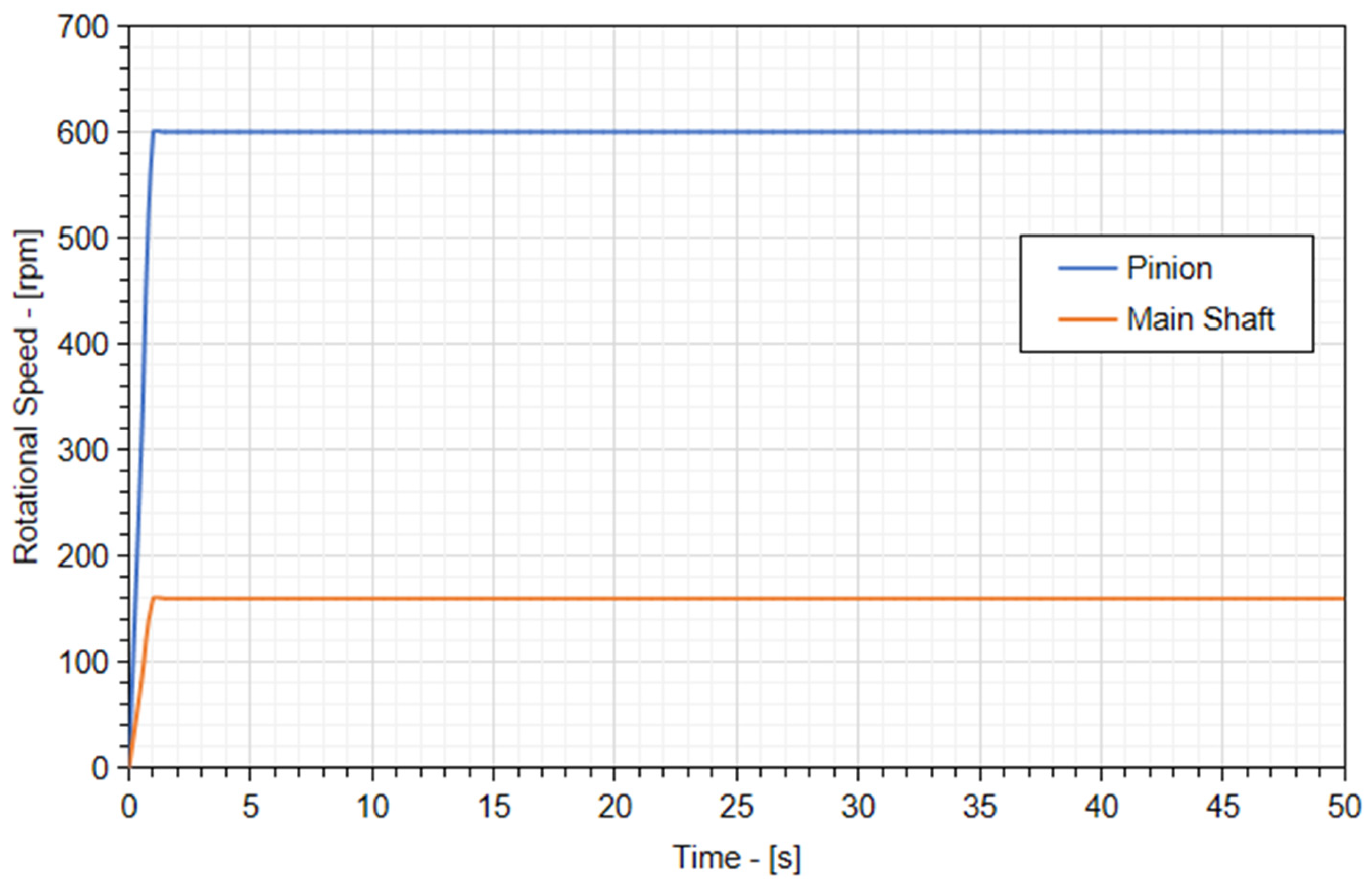
Figure 2b. MBD simulation was initially conducted with no particle fed into the system. Under this condition, the rated top speed for the mantle is 600 RPM, which is driven by the pinion with a gear ratio of 3.75 and a rotating speed of 160 RPM. Such standard settings were verified by the established MBD model and results are shown in
Figure 3.
3. GPU-Based Discrete Element Modelling
3.1. DEM Governing Equations and GPU Implementation
In DEM, a particle in a granular system has two types of motion: translational and rotational, which are determined by Newton’s second law of motion. Governing equations for the translational and rotational motion of particle i with radius Ri, mass mi, and moment of inertia Ii can be written as
where
vi and
ωi are the translational and angular velocities of the particle, respectively, and
kc is the number of particles in interaction. The forces involved are as follows: the gravitational force
mig, and interparticle forces between particles, which include elastic force
fc,ij, and viscous damping force
fd,ij. These interparticle forces can be resolved into normal and tangential components at a contact point. The torque acting on particle
i by particle
j includes two components:
Mt,ij, which is generated by tangential force and causes particle
i to rotate, and
Mr,ij, which is commonly known as the rolling friction torque. The rolling friction torque is generated by asymmetric normal forces, and slows down the relative rotation between particles.
Mn,ij is the torque generated by the non-spherical particles as the contact force between two particles may not go through the centre. A particle may undergo multiple interactions, so the individual interaction forces and torques are summed over the
kc particles interacting with particle
i.
DEM has been applied to particle systems for many years, and its implementation on CPU has been well documented. Generally, there are four key steps for DEM: particle grid partitioning and sorting, neighbour list generation, force calculation, and particle information updating. When DEM is implemented on the GPU, the framework is similar to the conventional sequential algorithm on the CPU, but the four major steps of DEM are exerted on the GPU. From previous studies, the speed up ratio of a single GPU device to a single CPU could reach as high as 30–1000, depending on the parallelization algorithm and the GPU graphic processor performance [
23,
24].
3.2. DEM Particle Breakage Model
Three different approaches have been developed in past studies to model particle breakage within DEM: the bonded-particle model (BPM) [
16], the fast-breakage model (FBM) [
20], and the particle replacement model (PRM) [
37].
As shown in
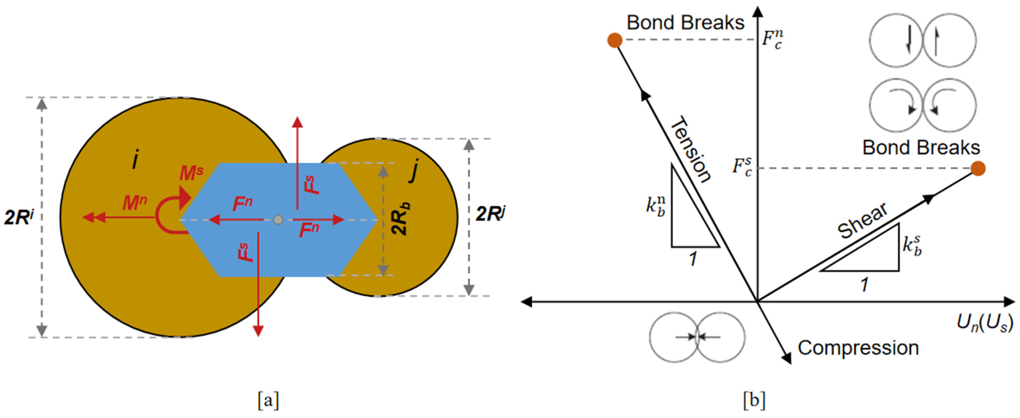
Figure 4, the bonded-particle model (BPM) was developed to directly mimic the particle breakage behaviours of irregular-shaped granular materials, in which bonds may break when stress exceeds a critical threshold. The BPM conceptual model can, in principle, be explained by several aspects of the mechanical behaviour of the particle. BPM has been widely used to investigate the rock mechanics. This model is capable of describing the breakage of quasi-brittle materials, that is, materials that exhibit subcritical cracking growth prior to catastrophic failure. It has also been used to simulate size reduction processes, including ball mills, wheat mills, and cone crushers. However, setting up an industrial-scale BPM model requires significant computational effort, for which GPU DEM is more suited.
The fast-breakage model (FBM) is a Laguerre–Voronoi tessellation-based [
38] particle breakage method developed to simulate fragmentation [
39]. A linear hysteresis contact model is typically used to describe the contacts between particles [
37]. Additionally, the particle replacement model (PRM), as originally proposed by Cleary [
40], consists of instantaneously replacing a particle, which could be shaped either as individual spheres, clumped spheres, or Superquadrics. Readers are directed to the relevant literature for a detailed theoretical background.
In this work, a GPU-based DEM breakage model was developed by coupling with a bonded-particle model. The BPM model (
Figure 4) proposed by Potyondy and Cundall was adopted to describe the interparticle bonding forces and torques which are calculated incrementally, given by
where
kn and
ks are the bond normal and tangential stiffness. ∆δ
n, ∆δ
s, ∆θ
n, and ∆θ
s are the incremental displacements and rotation in the normal and tangential directions. For a bond with radius
Rb and length
Lb, its bonding area is
, its moment of inertia is
, and its polar moment of inertia is
. Bonds can break either by tensile or shear stress and the criteria for bond failure are given by
where
σb is the strength of the bonds. Once broken, these bonds can no longer be restored. In this work, the bonding area is set to be proportional to the contact area between particles. Within a group of bonded particles, bonds are generated with the bond stress following a normal distribution as shown in Equation (8).
is the bonding strength;
N is a random number following the standard normal distribution;
Sc is the critical bonding strength.
Typically, a bond stress distribution range of 0.4~1.6 was utilised [
41].
3.3. Particle Breakage Model Setting
In the DEM breakage model proposed, a BPM approach as reported by Quist and Evertsson [
42] was used for simulating rock breakage in various comminution devices. The DEM and bonded-particle model settings are given in
Table 1.
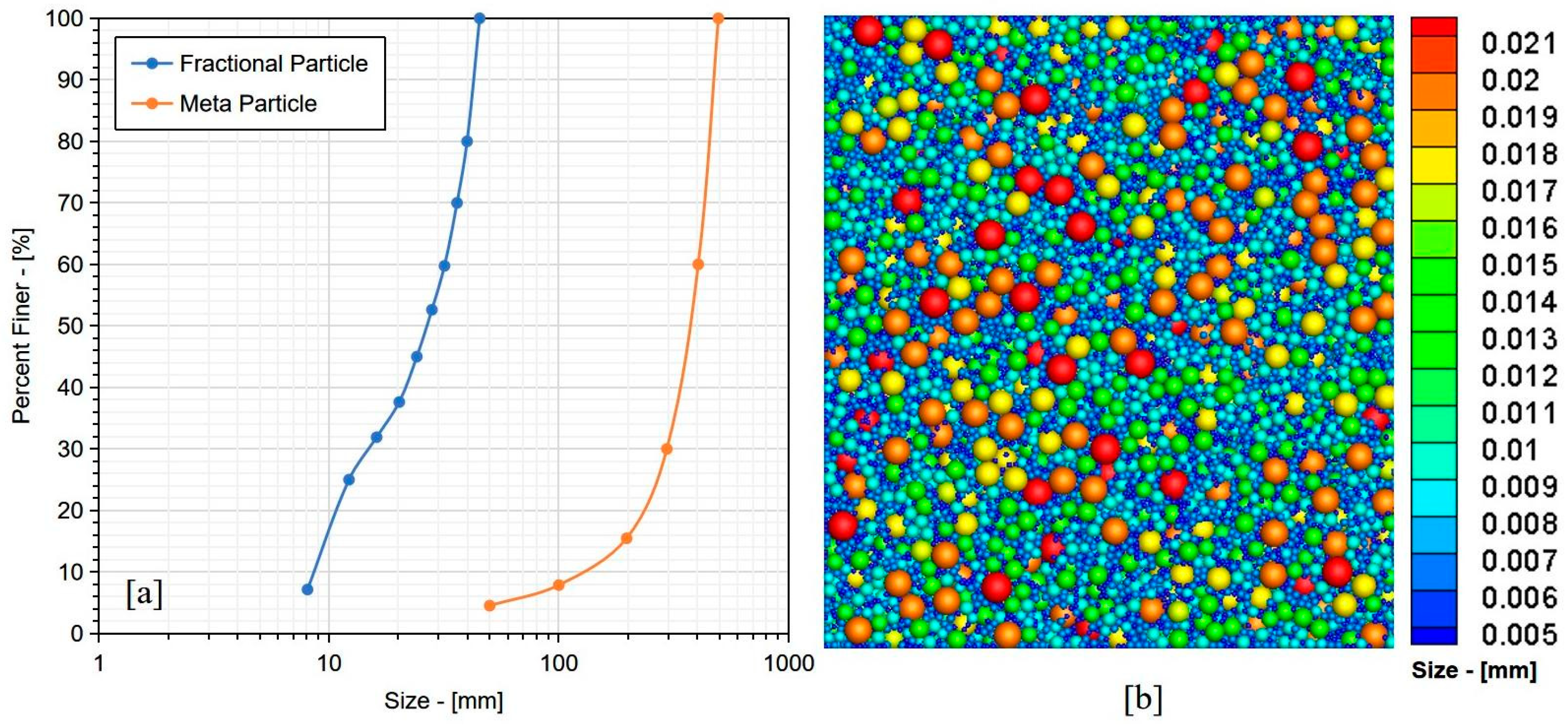
The meta-particle generation method is critical in ensuring the modelling is computationally efficient, and the appropriate level of fines tracking after crushing is achieved. To begin with, a nominal range of 50–500 mm for the meta-particle size distribution was selected for the feed to the crusher, and a fractional particle size distribution of 8–45 mm was used. Then, a library of bonded meta-particles was created following the steps below using a static factory approach:
A 3D geometry emulating the meta-particle shape was imported from 3D-scanned rock geometry. A polyhedral particle library was generated based on the scanned rock geometry and the Delaunay Triangulation algorithm, as shown in
Figure 5. A size distribution of meta- and fractional particles was predetermined, as shown
Figure 5. Particles were created inside the geometry factory with the predefined meta-particle size distribution, as given in
Figure 6.
Figure 7 shows meta-particles with different sizes.
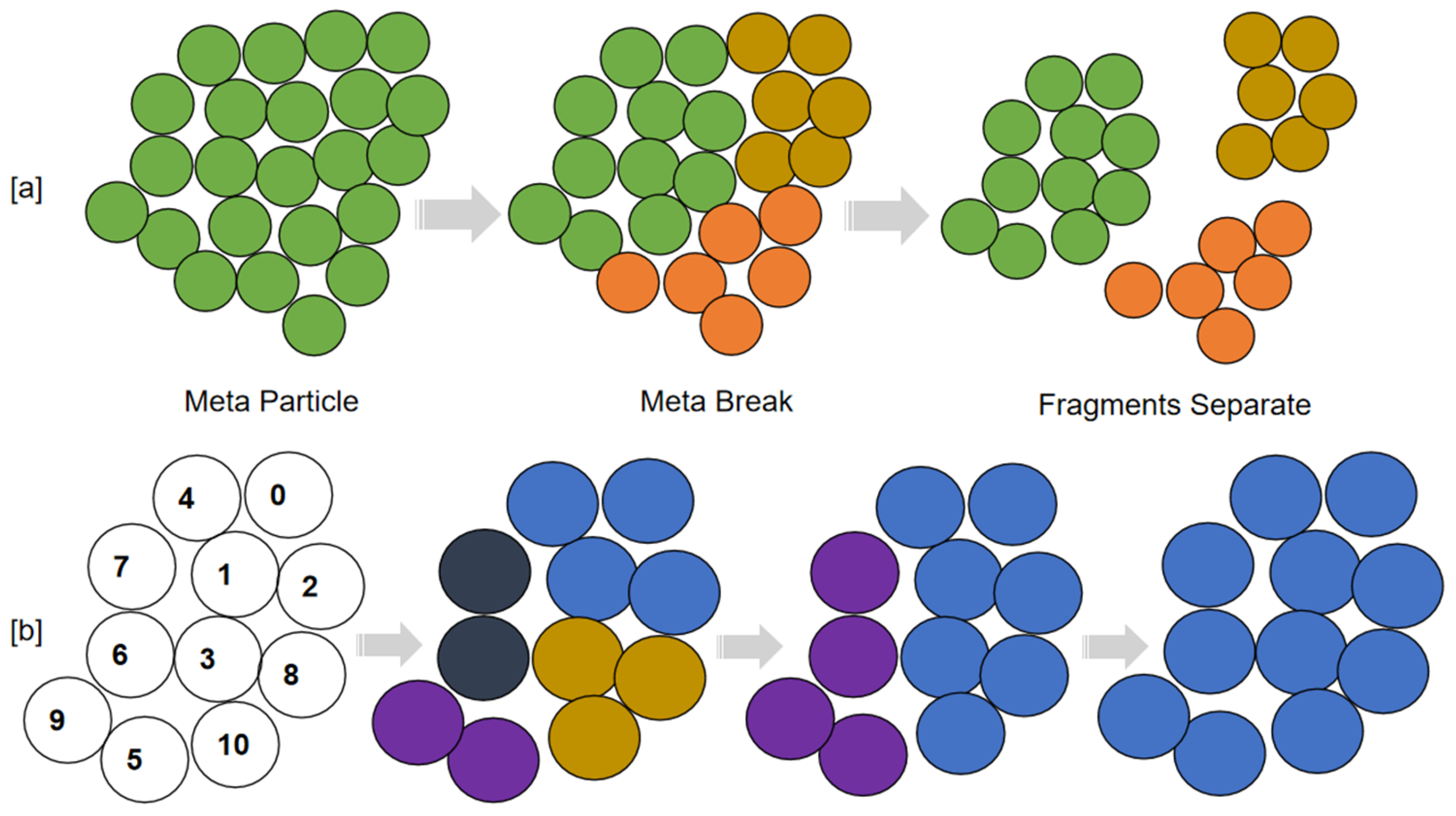
Based on the BPM concept, bonds can break either by tensile or shear stress according to the bond failure criteria in Equation (7). After critical bonds break, a meta-particle can break into several fragments, as shown in
Figure 8. In order to study the breakage mechanism (e.g., fragments numbers and break locations) and to collect the product size distribution, fragments need to be tracked from the meta-particle system. In the literature, the fragment size was estimated by analysing 2D images of the particles using the image processing technique. Other methods, such as looping over all the particles involved in a meta-particle and bonding particles back together, are also used. These methods are rather computationally expansive, and fragments cannot be visualised during simulation.
In order to efficiently identify the fragments and the product size distribution, a “Reduce-Map” algorithm is used. Firstly, with sorted bonding candidate pairs, the particle j in pair i–j (j > i) is reduced to the local root particle i. This step is parallelized with the total number of contact pairs. Then both particles are mapped into the local clump ID. This step is parallelized with the total number of particles in the system. The above two steps are repeated until all local clumps are mapped into the root particle ID. Generally, the fragment identification process needs 4–5 iterations of the “Reduce-Map” computation.
4. Cosimulation Framework
A code developed in-house was utilised in this study [
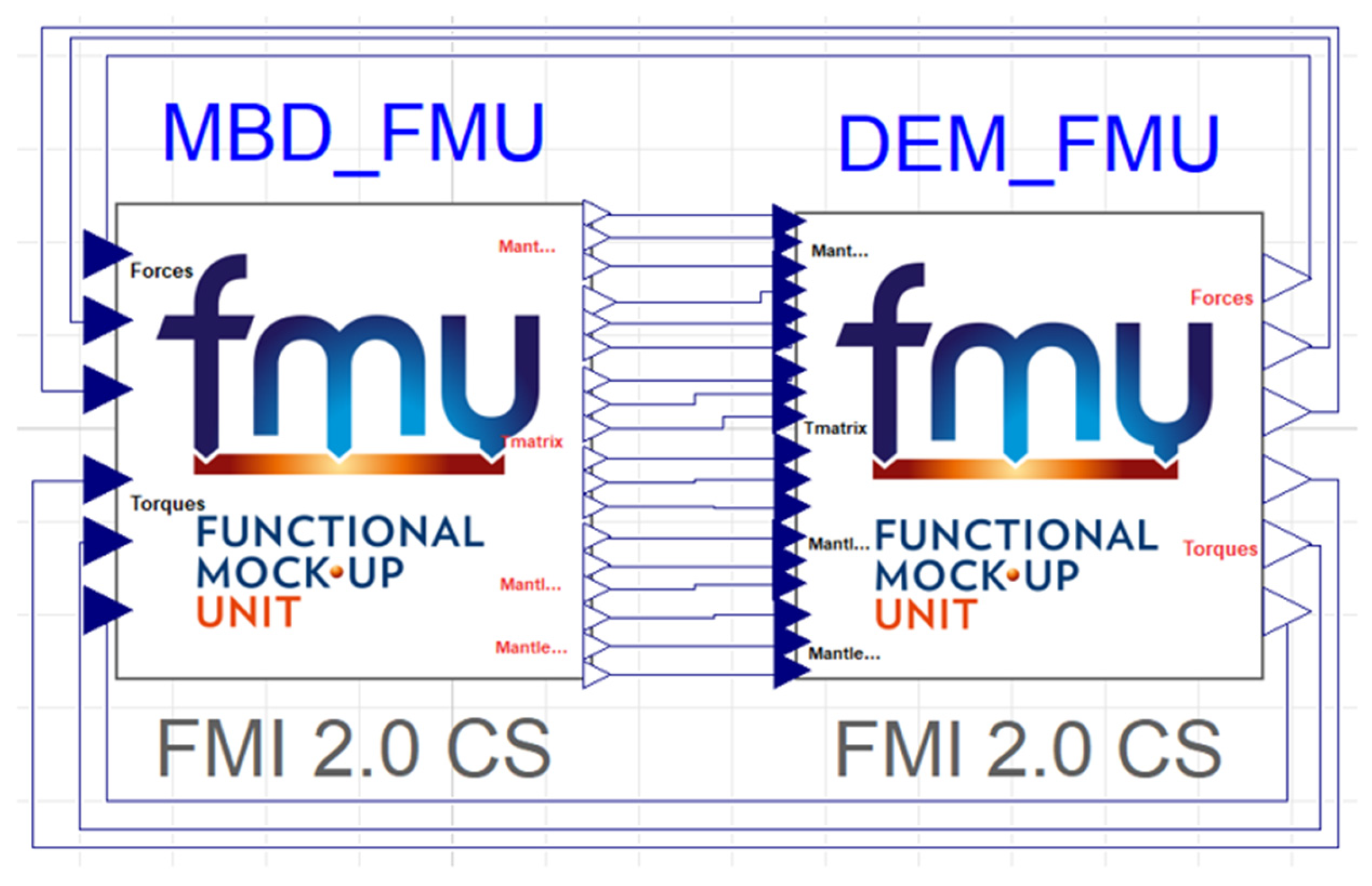
24]. The MBD and DEM models were coupled through the FMI framework. When both MBD and DEM models were ready, Functional Mock-up Units (FMU) files for each model could be generated, and the interactive contacts between particles and mantle surface were exchanged through FMUs, as shown in
Figure 9. The force and torque results between the mantle and particles modelled by the DEM phase were generated, and were subsequently transferred to the MBD models. Within MBD, the resulting performance of the drivetrain and the mantle motion were solved using the Cvode solver, and results were transferred to the DEM phase to fullfil the cosimulation cycle. The GPU-based DEM modelling typically takes a number of days to fully solve a couple of seconds of simulation, depending on the hardware specifications. While in MBD, the simulation is much quicker and only lasts a few minutes for the same duration of modelling. Thus, the DEM component undoubtedly determines the overall simulation time span. In order to improve the numerical stability of MBD-DEM data communication, an FMU communication interval of 1000 (5 × 10
−4 s time step for MBD and 5 × 10
−7 s time step for DEM) was used for the crusher cosimulation [
41].
5. Results and Discussion
Based on the numerical framework developed above, gyratory crusher modelling was conducted and the effects of the metal filling method, bond distribution, and bond diameter on the modelling results were investigated. The results are discussed below.
5.1. Rock Flow Pattern and Drivetrain Performance
The rock breakage and flow pattern in the crusher cavity were initially evaluated. A nominal range of 50–500 mm for the meta-particle size distribution was selected for the feed to the crusher, and a fractional particle size distribution of 8–45 mm was used. The following parallel bond parameters were also used:
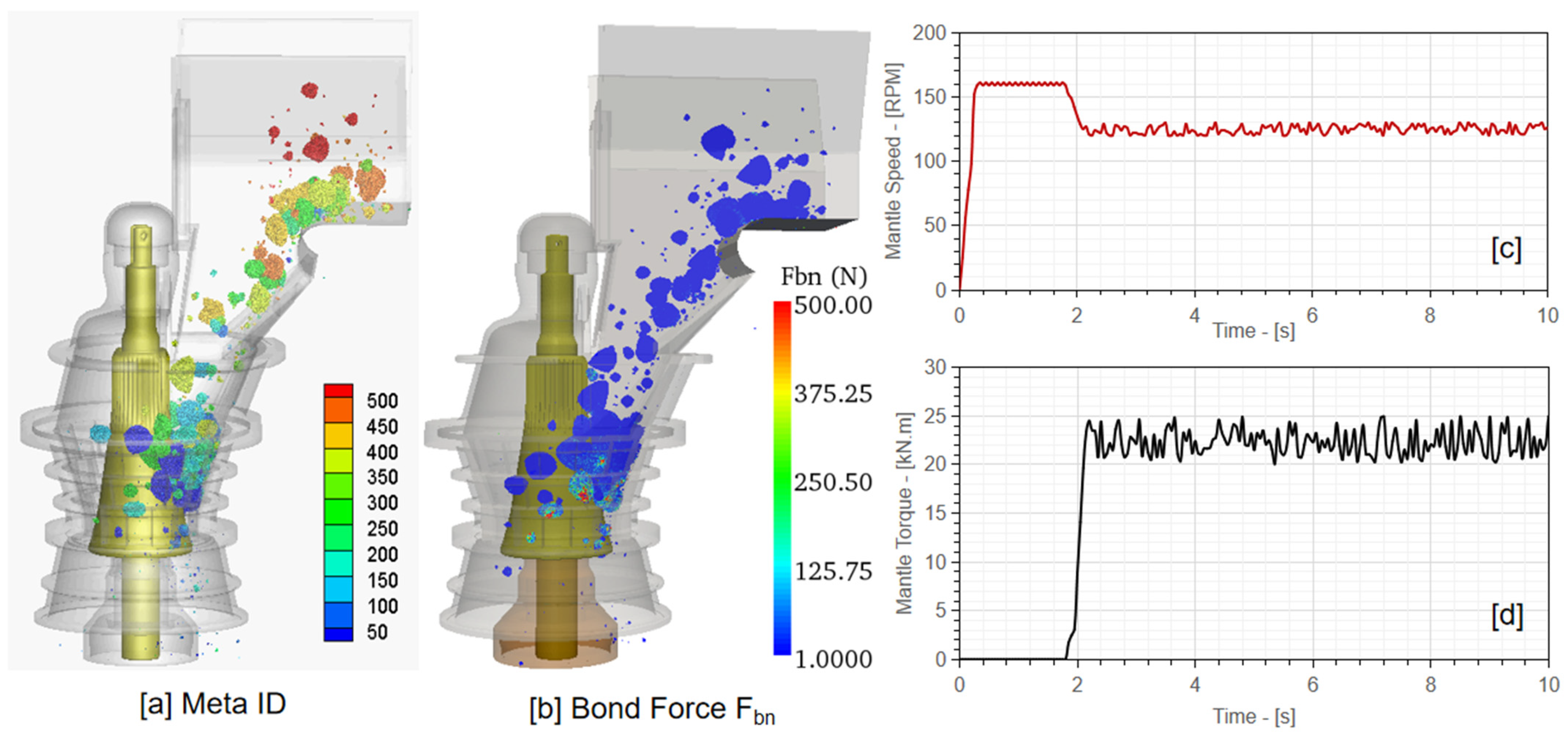
Modelling results are shown in
Figure 10a for the particle ID distribution and in
Figure 10b for the bond force distribution. The corresponding drivetrain performance of the modelling case was also obtained and is shown in
Figure 10c,d for the mantle speed and torque.
As the material was continuously fed into the crusher, meta-particles flowed down into the crusher cavity and the crushing mechanism was induced. Once the crushing mechanism was initiated, the mantle speed obtained from the MBD system gradually reduced from the nominal 160 rpm level to around 125 rpm. Conversely, the transient mantle torque increased from zero to approximately 21 kN·m. Once the size of a meta-particle was reduced to a sufficiently small level, it discharged out of the crushing cavity.
In terms of the particle breakage behaviours,
Figure 10b shows the variation in the transient bonding force (
Fbn) experienced by the meta-particles during crushing. It was observed that higher bonding forces were predominantly induced to the meta-particles when they were in close contact with the concave and mantle surfaces. When the crushing force experienced by the meta-particles was larger than the bonding stress, meta-particles broke into smaller meta-particles for further interactions with the crusher geometry.
5.2. Effect of Meta Filling Methods
The number of fractional particles in a meta-particle directly affects the magnitude of the entire granular system. When the packing of meta-particles is too fine, the GPU global memory is rapidly consumed, and the computational efficiency is greatly reduced. The following bond parameter settings were as follows:
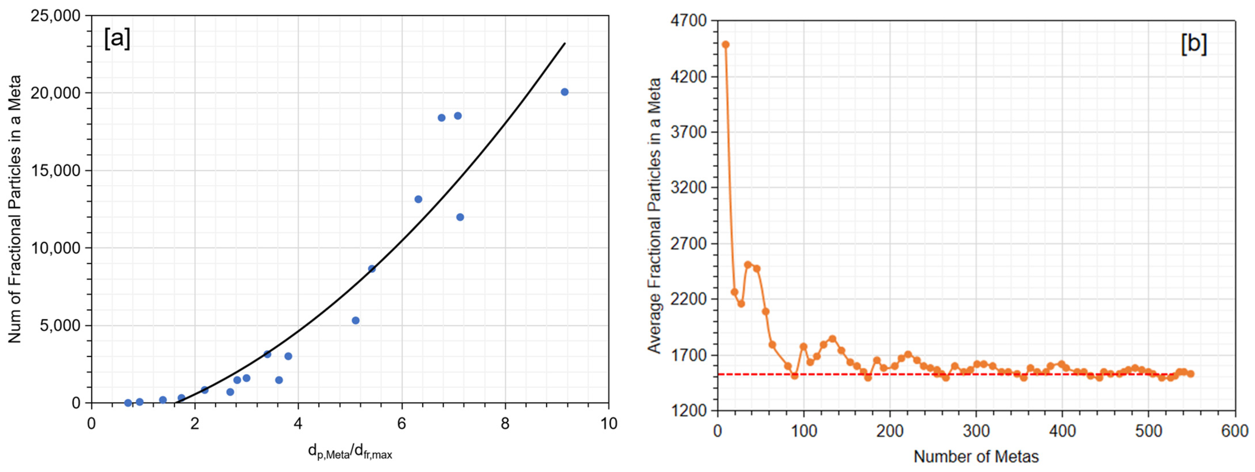
Based on these settings, a nominal range of 50–500 mm for the meta-particle size distribution was selected for the feed to the crusher, and a fractional particle size distribution of 8–45 mm was used. Based on the aforementioned settings, the total number of fractional particles within a meta-particle may range from 50 to 20,000, as shown in
Figure 11a. By increasing the population of the meta-particles, the total number of fractional particles in the simulation could be reduced, but it averaged around 1500, as shown in
Figure 11b, which still requires substantial computational efforts. In comparison, if a relatively large and mono-sized fractional particle is selected, the total number of fractional particles in one meta-particle can be greatly reduced. Finer fractional particle size settings may assist in tracking the fines after crushing, but at the cost of the computational efficiency. Therefore, the meta-particle filling method requires careful balancing of the crushing behaviour (fines tracking with wider fractional particle size distribution) and computational efforts (mono-sized fractional particles).
Based on the discussion above, the use of mono-sized fractional particles was also investigated. Three different
dMeta/dfractional ratios, 10, 6, and 2, were utilised for comparison purposes, and the corresponding number of fractional particles in a meta-particle was calculated. As shown in
Figure 12, when
dMeta/dfractional was selected as 10, 6, and 2, the total fractional particles in a meta-particle reduced from 640 to 140, and then 40, which greatly assisted in GPU global memory reduction.
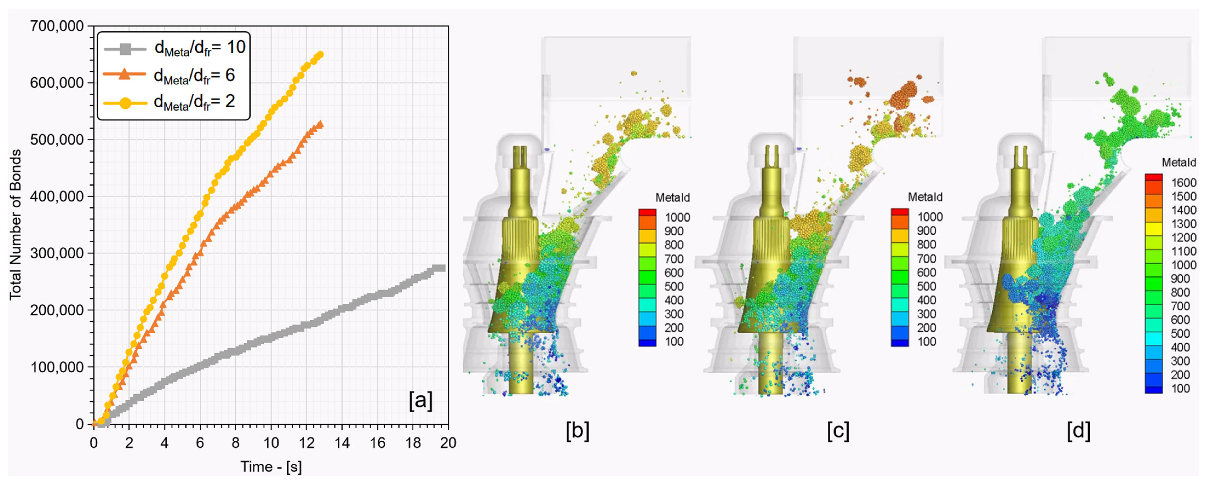
With the three mono-sized fractional particle options discussed, crusher modelling was also conducted, and associated total bonds during the crushing were also tracked. As shown in
Figure 13a, the use of the smaller
dMeta/dfractional ratio resulted in a significant reduction in the total bonds in the simulation, which would improve the computational efficiency. Comparing the ore flow and crushing behaviours of different
dMeta/dfractional ratios shown in
Figure 13b–d, a minor difference was observed across three settings. For the purpose of better tracking of fine particle size distribution in the product stream, as well as considering computational efficiency,
dMeta/dfractional = 6 was selected for further modelling cases conducted below.
5.3. Effect of Bond Distribution
Based on aforementioned settings, the typical bond stress falls in a range of 0.4–1.6 times the critical bond stress. In this section, the effect of the bond stress distribution was studied using the feed size range of 50–500 mm with a mono-sized fractional particle size setting of
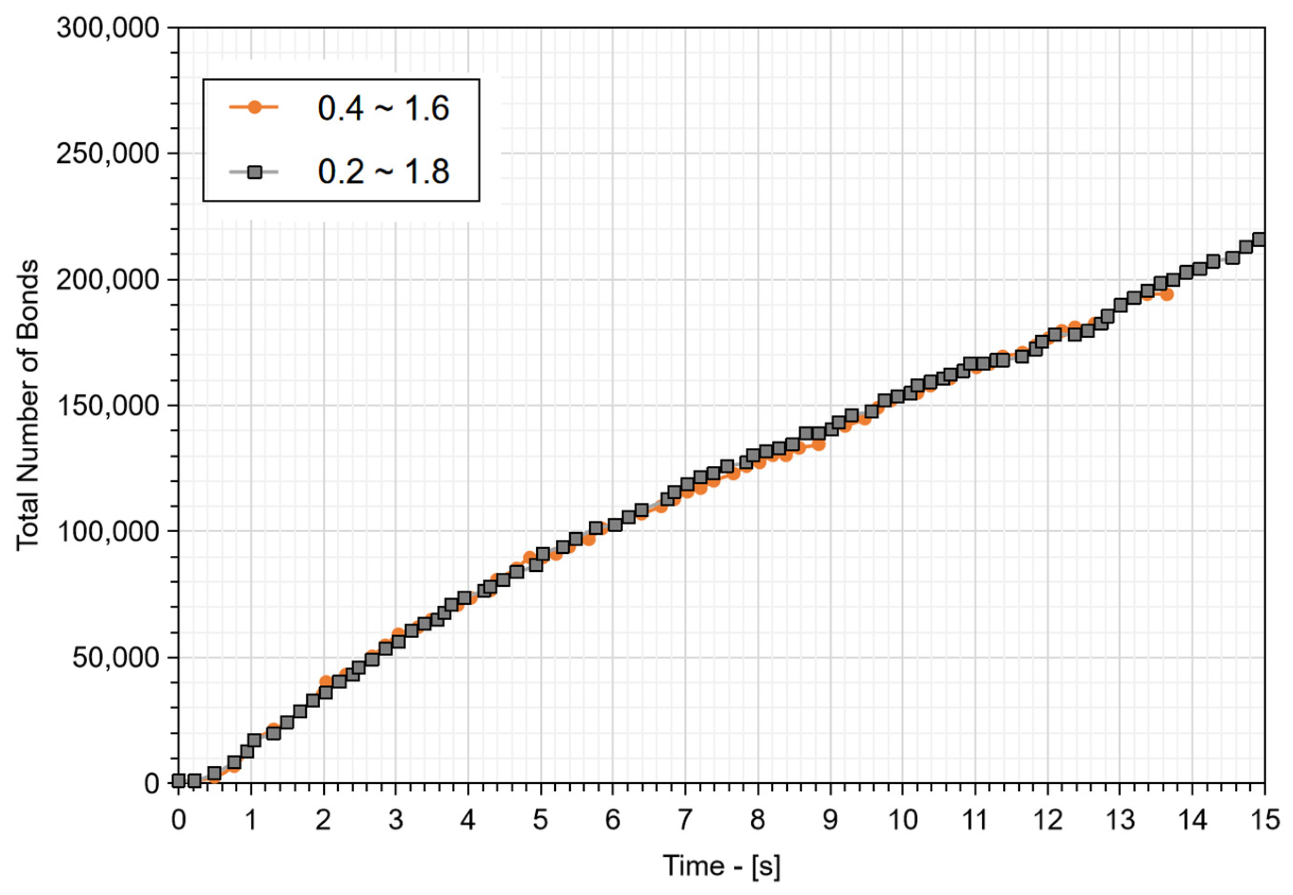
dMeta/dfractional ratio = 6. An alternative bond stress range of 0.2–1.8 was utilised to compare the total bonds generation in each case and the results are shown in
Figure 14. They indicated that the total number of bonds increased marginally when the bond stress range of 0.2–1.8 was selected. No visible difference was observed in the ore flow and crushing performance across the two different bond stress ranges. Therefore, it was suggested that the effect of bond stress range can be neglected, and a nominal range of 0.4–1.6 can be selected.
5.4. Effect of Bond Radius
In the BPM model, the normal and tangential bond force and torque, and the bond failure criteria are all related to the bond area
, where
is the bond radius. Therefore, the actual strength of the rock particle is directly correlated to the bond radius setting. Under fixed normal and tangential critical failure stress levels as shown in
Table 1, when a smaller bond radius was selected, the resulting normal and tangential stresses were higher, leading to rock particles more easily fragmented under the induced crushing force. Thus, an appropriate level of bond radius is critical to ensure the rock is not too “hard”, nor too “soft”, when interacting with the mantle and concave. In this study, the effect of the bond diameter on the crushing behaviours was investigated. Essentially, the following settings were selected while increasing the bond diameter in the range of
Rb = [0.1
Rfractional, 0.5
Rfractional,
Rfractional,]:
Meta-particle size distribution: 50–500 mm
Fractional particle size distribution: mono-sized with dMeta/dfractional = 6
Bond stress range: 0.4–1.6
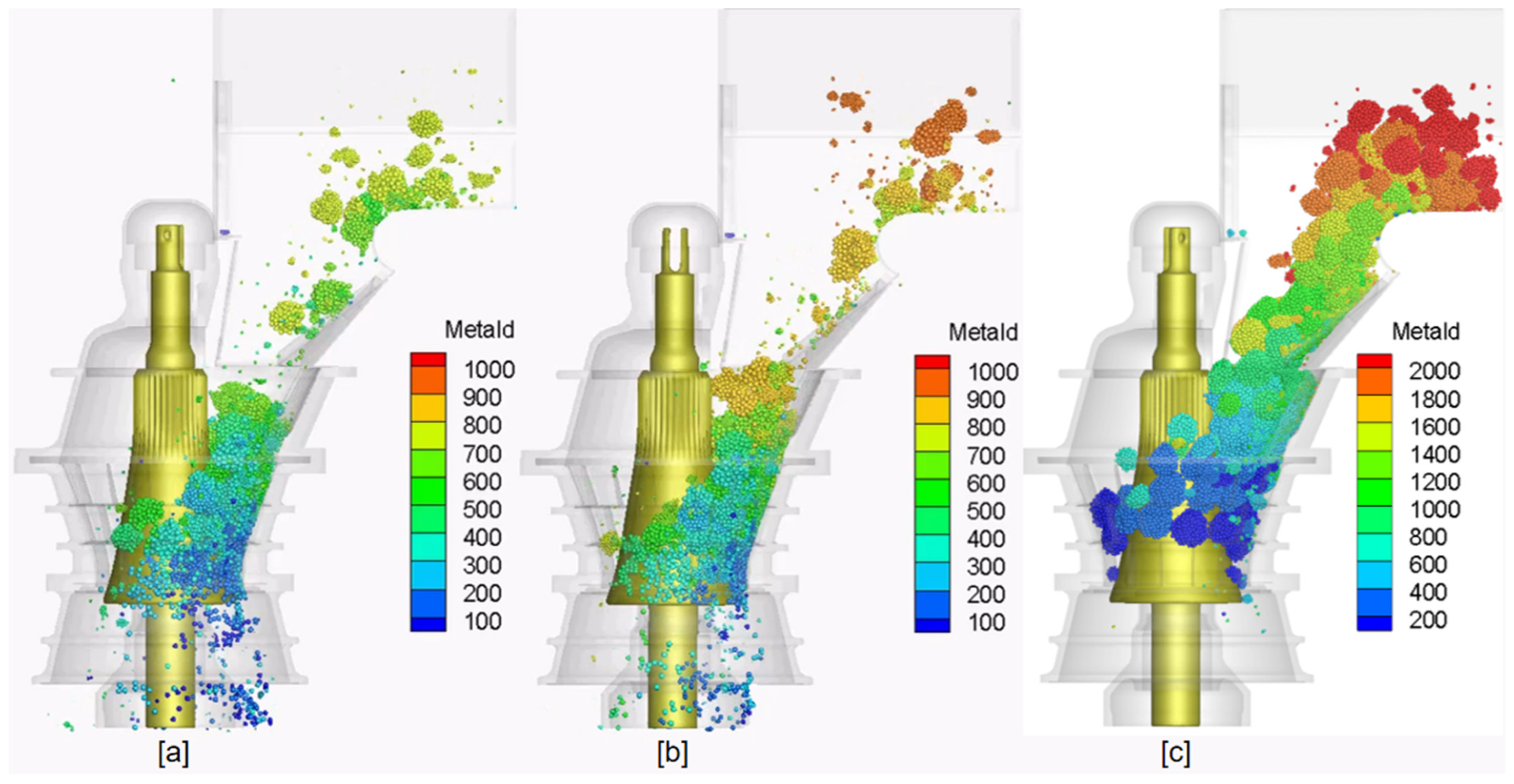
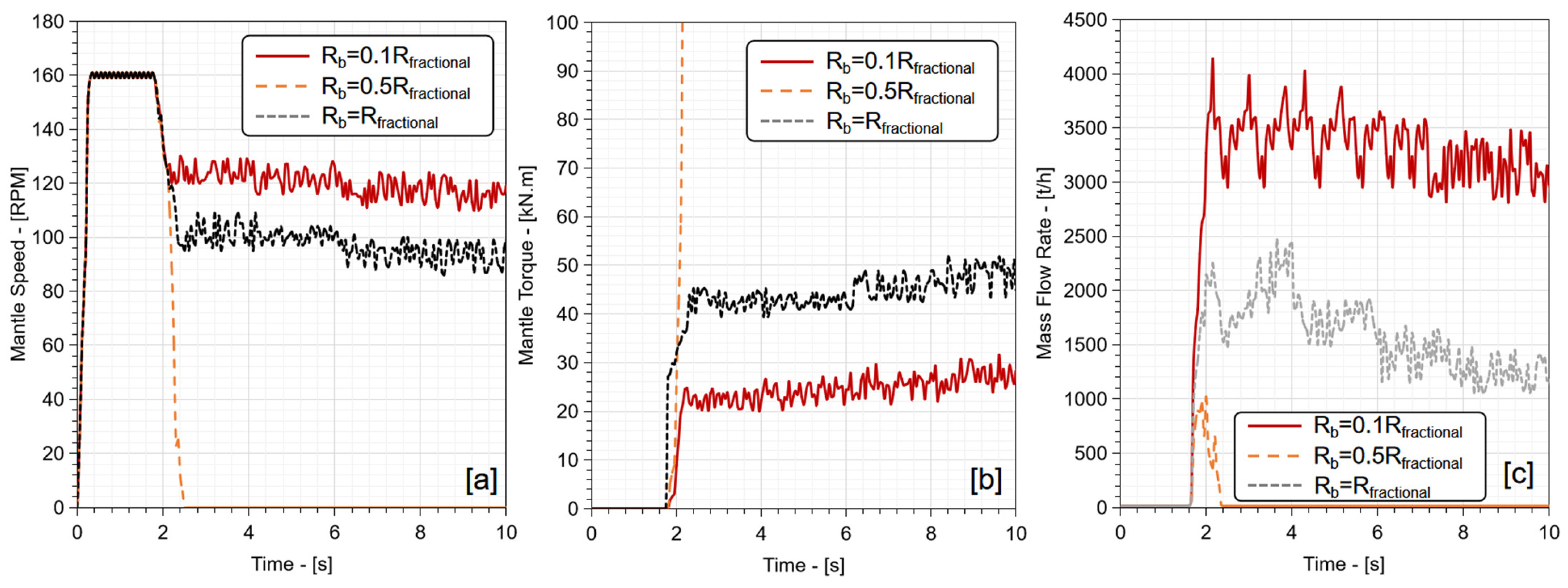
Figure 15 shows the rock flow behaviours in DEM and MBD systems under the three distinct bond radius settings. When the bond radius was set to be equal to the fractional particle size (
Rb =
Rfractional), the resulting bond stress was too high, rocks were more difficult to break, and a minimal discharge mass flow rate was observed in
Figure 15c. This was further validated by the mantle speed and torque obtained from MBD modelling as shown in
Figure 16a–c. When the material was fed into the crusher, the mantle torque increased substantially while the mantle rotational speed dropped to zero rapidly, indicating that the drivetrain was overloaded. In comparison, when an intermediate bond radius (
Rb = 0.5
Rfractional) was selected, normal crushing and product stream discharge were observed; however, the mantle torque, speed, and the discharge mass flow rate were observed to be reduced compared with the modelling results from the bond radius of
Rb = 0.1
Rfractional.
The evolution of crushing and drivetrain performance with respect to the bond radius indicated that the developed DEM-MBD cosimulation framework was able to cover a number of different working modes of the gyratory crusher, from high throughput with relatively “soft” ores to choked conditions with “hard” ores. In comparison to the typical crusher performance from the manufacturer, a nominal max throughput of 3720 tph [
8] was provided based on a feed particle density of 2750 kg/m
3. Such a performance is within the range of the throughput obtained above with
Rb = 0.1
Rfractional.
Compared with the conventional DEM-only method, the addition of the MBD system enables the drivetrain to react based on the ore properties, which reflects more closely the real gyratory crusher operations. In addition, when attempting to optimise the crusher design with the DEM-MBD framework, once a suitable meta filling method and fractional particle size are selected, it is important to perform rock breakage calibration to ensure the “hardness” of the meta-particles is properly reflected during the crushing process.
6. Conclusions
A comprehensive study on developing a discrete element modelling (DEM) and multibody dynamics (MBD) cosimulation framework for modelling the gyratory crusher was conducted. A GPU-based DEM framework was developed by incorporating a bonded-particle method for modelling particle breakage. A Modelica-based MBD framework was introduced into the DEM to simulate the transient response of the crusher’s drivetrain. The modelling results of a full-scale gyratory crusher suggested that transient rock flow, rock crushing, mantle speed, and mantle torque can be obtained using the DEM-MBD modelling framework. The effect of the meta-particle filling method was studied and a mono-sized fractional particle setting with dMeta/dfractional = 6 was suggested for the GPU-based computational granular system. The effect of the bond stress distribution range was investigated, and the results suggested the bond stress distribution exhibited negligible impact on the bonds generation during simulation. The bond radius exhibited significant impacts on the crusher’s performance, and different modes of crushing performance in terms of mass flow rate, mantle speed, and torque were obtained by tuning the bond radius settings. Consequently, the developed DEM-MBD modelling framework provides a holistic evaluation and optimisation framework for the design and improvement of gyratory crushers.
