Article

Process Optimization of an In-Situ Bioleaching Section with Associated Membrane Filtration in a Field Test Laboratory

by
Katja Götze
1,*,
Sabrina Hedrich
2,
Andreas Siegfried Braeuer
1 and
Roland Haseneder
1
1
Institute of Thermal, Environmental and Resources’ Process Engineering, TU Bergakademie Freiberg, 09596 Freiberg, Germany
2
Institute of Biosciences, TU Bergakademie Freiberg, 09596 Freiberg, Germany
*
Author to whom correspondence should be addressed.
Minerals 2024, 14(3), 308; https://doi.org/10.3390/min14030308
Submission received: 31 January 2024 / Revised: 5 March 2024 / Accepted: 8 March 2024 / Published: 15 March 2024

Abstract

:
The winning of critical raw materials from secondary resources, e.g., from abandoned mines, mining residues, electronic waste or low-grade ores, is a potential source with promising outcomes due to innovative and more efficient extraction methods. The research and education mine “Reiche Zeche” at the TU Bergakademie Freiberg, Germany offers a scientific lab in a real application environment for an in-situ bioleaching section from a low-grade sulfide ore vein with on-site associated membrane downstream processing. The evaluation and resumption of previous research activities showed both the feasibility and the potential for further up-scaling. But there was also potential evaluated for improving the effectiveness, especially in terms of individual process elements within the leaching and membrane cycle as well as regarding microbiology. Based on this, further optimization was carried out and effectiveness was evaluated and compared to the prior state. The results regarding the leaching outcome proved that process optimization leads to stable and continuous leaching process operations as well as to improved and more favorable conditions for the microorganisms due to the implementation of a bioreactor and changing the whole leaching operation from a direct into an indirect process. Furthermore, cleaning in place (CIP) resulted in the maintenance of selectivity despite discontinuous membrane process operation.

1. Introduction

The extraction of critical raw materials from secondary resources such as mining residues, tailings or electronic waste as well as from low-grade ores is a promising resource to make an important contribution to meet the demand for raw materials [1]. Compared to traditional methods, innovative and environmentally benign process solutions have immense potential. In-situ leaching with the help of microorganisms offer the possibility to extract metals from low-grade ores with minimal impact on the surrounding environment, especially when it is performed in-situ (directly within the ore vein), compared to traditional mining with subsequent heap leaching. The extraction process leads to a metal ion-enriched solution (PLS—pregnant leach solution) which can be further processed by conventional hydrometallurgical methods like solvent extraction and electrowinning (SX/EW). Although during the last number of decades SX/EW processes have emerged regarding their environmental impacts, there is still potential to improve their sustainability [2]. Combining in-situ leaching with on-site selective membrane downstream processing to win defined concentrated solutions could be one promising option to increase the efficacy and lower the environmental impact of subsequent extraction processes.
In principle, bioleaching is a natural well-known phenomenon, e.g., at Noguera de Vallferrera (Central Pyrenees); Río Tinto (Spain) or the Morenci porphyry copper deposit (AZ, USA) [3,4,5,6]. In previous decades, projects based on microbial active mine waters have been started to leach low-grade ores on the scale of tons. A famous example is the Mynydd Parys mine in Anglesey, Wales, where since the end of the 19th century copper recovery from acid mine drainage (AMD) was carried out within the so-called “cementation process”. AMD was fed into large iron scrap-containing ponds to produce up to 50 t of copper a year [7]. Other industrial-scale examples include almost exclusively mined ore, ground and crushed with subsequent biological leaching of the accumulated material (heap leaching) above ground, or the bioleaching within reactors [8,9]. In-situ uranium leaching with the help of bacteria was carried out in the Standrock Ltd. uranium mine in Elliot Lake, Ontario, Canada even before 1965 [10,11]. Generally, up to now, in-situ leaching via acids and wells for uranium recovery comprises more than 55% (2022) of the worldwide uranium production [12]. Also, (bio)heap leaching is the most common method for copper [13,14]. The (bio)leaching within reactors is, regarding the process costs, the most expensive one and, therefore, mostly used for highly valuable metals like gold [15,16]. In total, ore leaching processes are state of the art [17].
Nevertheless, in-situ bioleaching is not a common method yet. Although the process offers some advantages in principle—especially in terms of environmental aspects—the economic application of the process is still a challenge. Since many parameters affect bioleaching, the slow unpredictable process of in-situ bioleaching stands in the way of economic efficiency. As early as 1911, the conclusion was expressed that natural (microbiologically influenced) waters initiate an oxidation process that produces soluble copper salts. At the same time, it was found that: “oxidation, a process which goes on in an ore body exceedingly slowly, and Nature cannot be hurried” [18]. But, within recent decades, there have been some field test projects that proved principal feasibility. Among others, to be mentioned is the pilot-scale underground heap leaching at Avoca Mine, Ireland in the 1980s. Natural leaching solution from the mine ground was dropped over a pre-blasted ore body for continuous bioleaching. The sufficient supply of O2 within the ore body was identified as one of the most significant challenges [19,20,21]. Another project to be mentioned is the in-situ stope leaching at Ilba mine in Baia Mare, Romania, performed in 1990–1991 [22]. The ore body was pretreated by drilling and blasting and leached due to the irrigation by microbial sprinkling. Also here, among high leaching fluid losses, due to the angle of the ore body and sealing problems to the surrounding rock, optimal O2 supply, pH adjustment and uncontrolled Fe3+ precipitation—combined with sludge and cover layer formation—posed challenges. Overall, leaching could only be carried out at the first one-third of the ore body. It was concluded that directing the leaching solution could increase the effectiveness significantly [22,23]. A more recent example is set up within the EU project BioMOre (2015–2018) where chemical and biochemical in-situ block leaching was performed in 2018 as a pilot-scale application at the KGHM Polska Miedź SA copper mine in Rudna. Through drilling and blasting techniques, the fractured ore block was leached in combination with an on-site bioreactor for Fe3+ regeneration. Although principal feasibility was proved, the researchers had to face challenges especially due to the ore composition. Long washing steps were required to remove fine-grained particles, blasting residues and to dilute carbonates before the actual ore leaching. After leaching, further treatment had to be carried out to neutralize the ore block and to inactivate the leaching microorganisms [24,25,26]. Additional examples for in-situ and/or bioleaching can be found in [27,28,29,30,31].
Overall, it can be followed, that in-situ bioleaching may be a promising approach, especially for the extraction from low-grade ores and particularly at old mining sites. The weaknesses that still stand in the way of commercial/economic use become obvious, however. These mainly concern suitable conditions for the microorganisms (e.g., pH value, temperature and O2 supply), sufficient permeability of the whole ore block, high ore surfaces (regarding particle size, wetting of the ore, precipitation problems and leach flow pathways) as well as the ore composition (e.g., release of carbonates causing pH fluctuation or dissolving bacteria toxic elements) and the sealing to the surrounding rock to avoid unwanted leaching solution losses or dilution, causing potential ecologic and economic consequences.
The Bio-Hydrometallurgical Center for Strategic Elements (BHMZ) project (2013 to 2018) and follow-up project take the presented problems in several aspects into account. In the following, the results of the preceding BHMZ project are reviewed and subsequently compared with the results of the improvements made within the follow-up project, using the same setup. The research and education mine “Reiche Zeche” in Freiberg, Germany enables the collaborators of the BHMZ to research in a real application environment, by using old underground mining roads for the installation and operation of an in-situ bioleaching section with an associated hybrid membrane system for selective element recovery from pregnant leach solutions (PLS).
For that purpose, boreholes were drilled directly into a low-grade sulfide ore vein, which was perforated by different conditioning methods to increase the permeability of the ore. The leaching was carried out in a direct way and circulated between head and bottom road as can be schematically seen within Figure 1, also including the subsequent membrane downstream processing.
As can be seen in Figure 1 (step 1), the leaching is carried out by feeding the inlet boreholes with a microbial leaching solution, containing a high content of Fe3+. While permeating through the microcracks and fractures, the solution is enriched with metal ions, resulting in the so-called pregnant leach solution. The leaching cycle is directly linked to the hybrid on-site membrane system for the selective extraction of (metal) ions from the PLS (see Figure 1, step 2). Within the first filtration step of microfiltration, the microorganisms are concentrated within the retentate and returned to the leaching cycle. The resulting metal ion-rich permeate passes to a second filtration step, the nanofiltration. Hereby, the highly diverse component solution is selectively separated by a nanofiltration membrane. In case of the BHMZ, the selective winning of indium and germanium was set as a goal. Due to the selective NF membrane surface, cations, including indium, are enriched within the retentate while germanium can permeate through the membrane. After NF, there is the possibility to concentrate the permeate and retentate further by reverse osmosis to obtain defined, less complex and concentrated solutions for the subsequent metal winning by, e.g., SX/EW processes.
Previous comprehensive research activities allowed a wide-ranged characterization among others in terms of mineralogical, hydrogeological and microbiological as well as mining and process engineering questions. Even though the project reached a TRL of 6 (prototype in use in real application environment for 1–5 years), several things to be improved for an industrial application were identified [32]. These, among other factors, involve corrosion problems within the leaching section, maintaining a favorable pH value during leaching as well as a sufficient retention time of the leach solution at the ore surface. Furthermore, the optimization towards more suitable conditions for the microorganisms and thus, creating suitable and high reaction kinetic is intended. Also, microfiltration process parameters had to be improved to prevent membrane fouling and to maintain a sufficient membrane flux.
The adjustments made to achieve these goals are presented below in direct comparison to the previous state, divided into the areas of bioleaching, microbiology and membrane downstream processing.

2. Testing Environment and Evaluation of Optimization Potential

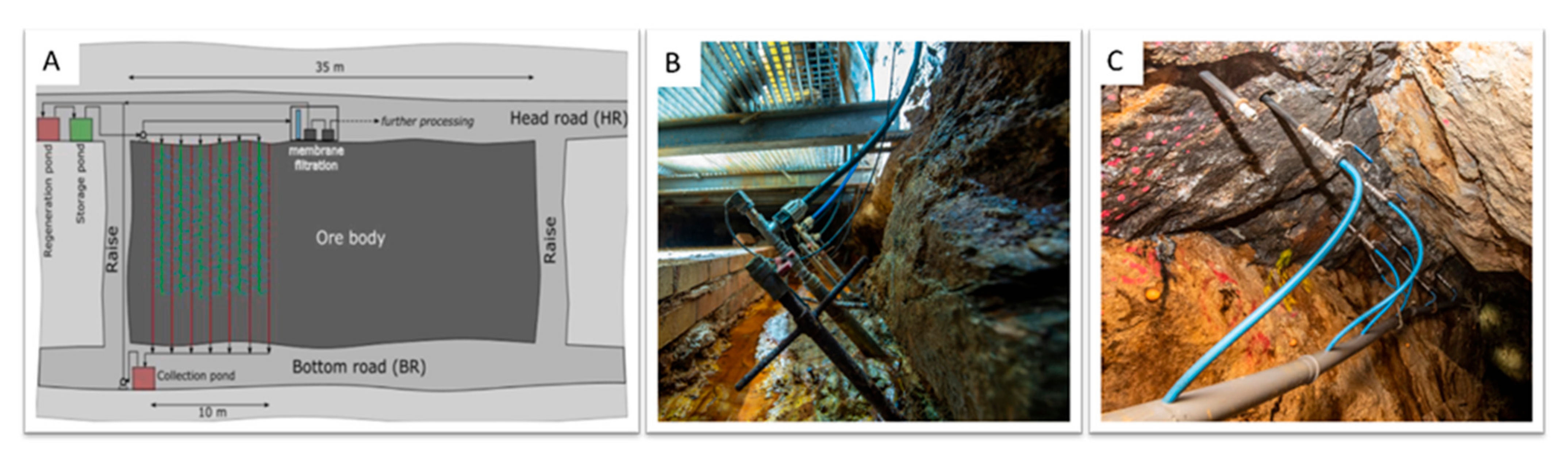
2.1. Geological and Hydrogeological Testing Site Conditions

The testing site is located 147 m underground with ambient conditions of approx. 12 °C and almost 100% humidity. The feeding and drainage boreholes of the leaching cycle were drilled into the so-called “Wilhelm Stehender Nord” ore vein. The hydrothermal polymetallic sulfide ore vein is orientated in a N–S direction with a dipping angle of ~50°, mineralized mainly by sphalerite (ZnS; high Fe content), galena (PbS), pyrite (FeS2), chalcopyrite (CuFeS2) and arsenopyrite (FeAsS). The thickness of the fissure vein varies between a few centimeters up to 1m and is bound above and below by “Freiberger” gneiss which is impermeable to the PLS. Indium and germanium, declared as target elements within the BHMZ, were found enriched within the sphalerite with In concentrations up to 70 ppm and Ge concentrations up to 0.4 ppm [33,34]. Furthermore, drill cores at the testing site were extensively analyzed regarding mineral composition, element concentrations and variations in spatial spread of the ore body. Geophysical methods (geoelectric and seismic), borehole tomography and induced polarization (IP) measurements have provided additional information in order to determine the direction and speed of dispersion of the PLS [35].

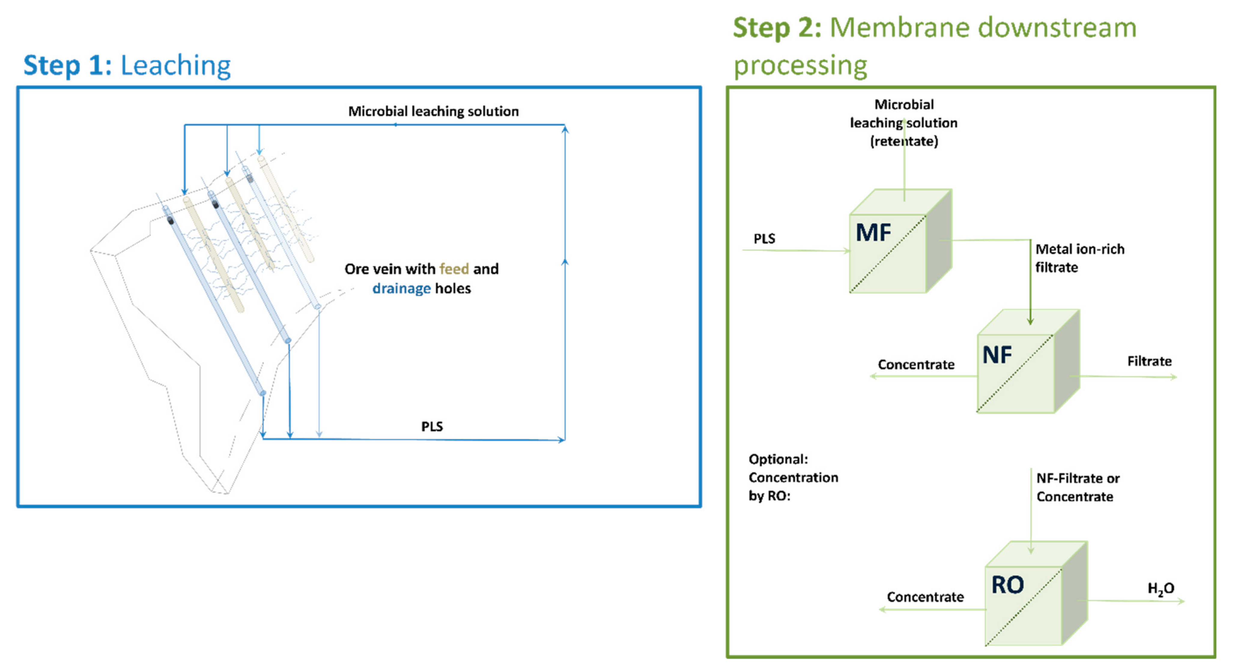
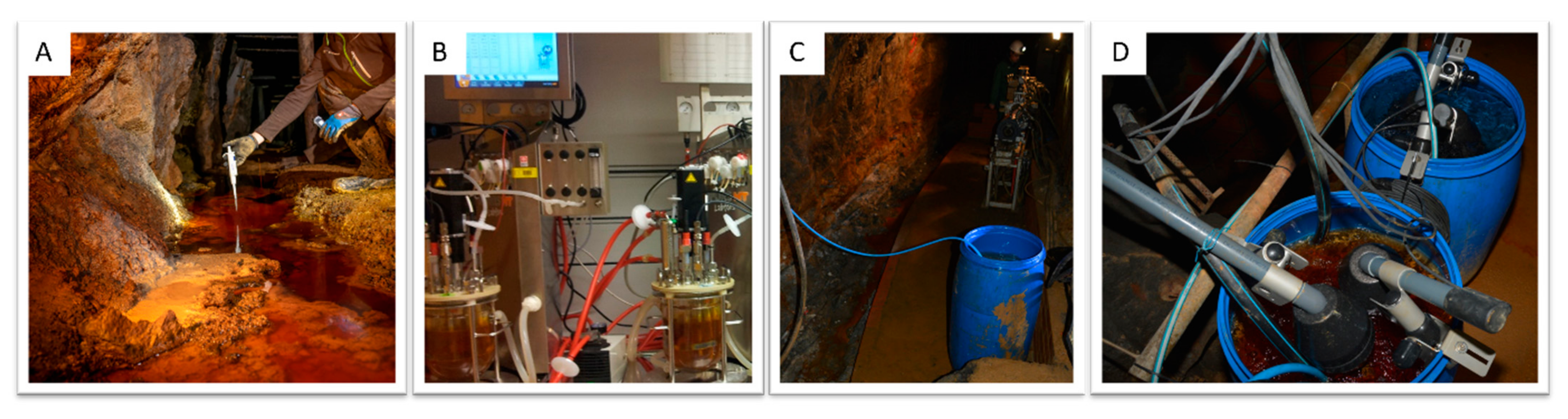
2.2. Bioleaching Setup

The selected testing site makes a part of the “Wilhelm Stehender Nord” accessible due to a head road, a bottom road and two laterally roads connecting head and bottom road as well as bounding the ore vein to an area of 35 × 10 m. To determine the best feasible positions for the feeding and drainage boreholes, as well as to evaluate the most suitable blasting technique for producing a high ore surface area in form of permeable fractures and microcracks, seismic and geoelectric measurements were performed. The measurements allowed the modeling of a geophysical block model of the ore vein and showed, especially at the lateral roads, highly weathered zones. In particular, for the drilling of the feed and drainage boreholes homogeneous areas with wave velocities between 5000 and 6000 m s−1 were selected [36,37]. A schematic sketch of the leaching section as well as feed and drainage boreholes at the head and bottom road, respectively, are shown in Figure 2.
Seven feed and eight drainage boreholes were drilled with a distance between each other from 0.23 m to 0.45 m and a diameter of 5.6 cm. The feed boreholes end about 3–4 m above the bottom road, while the drainage boreholes are continuous and closed towards the head road (see Figure 2A). To create flow paths for the PLS in form of microcracks and fractures between the feed and intermediate drainage boreholes, two different conditioning methods were applied [38]. One conditioning method was water pressure blasting. Due to its incompressibility water acts as a coupling medium, whereas a detonating cord is the source of pressure. In this way, high dynamic stress at the borehole wall was introduced and multiple cracks were created. The second method was a sequenced hydraulic stimulation using a double core straddle packer, resulting in cracks whose orientations were defined by the pressure level and the resulting in-situ stress. Conditioning increased the permeability between the feed and the drainage boreholes significantly by a factor of 3 to 8. At the beginning of the first on-site testing phase (2016), a total permeability for all boreholes for the bioleaching solution of 30 L h−1 (at 1 bar) was determined. In terms of achieving a suitable retention time for the leaching solution, permeability was considered as appropriate [36]. Control trials in 2018 and 2020 indicate a highly increased flow rate for some of the feeding boreholes due to the formation of preferential flow paths and thus an insufficient retention time [39]. Furthermore, the difficult material conditions (susceptibility to corrosion) hindered continuous operation of the almost fully automated leaching cycle.

2.3. Microbiology

For the conversion of insoluble metal sulfides into water-soluble ions a series of chemical, as well as biological reactions are needed. For the biological leaching of the sulfide ore to be found at the testing site, aerobic, acidophilic Fe2+ and sulfur compound oxidizing bacteria or archaea are involved. The mechanisms and reaction steps for various ores and organisms have been discussed in detail and researched in the past as can be looked up among others at [6,40,41,42,43,44].
The oxidation of metal sulfides is a chemical reaction due to the most relevant oxidizing agents Fe3+ and H+. Molecular oxygen is the final electron acceptor [6,42]. The metabolism of the microorganisms maintains not just the acidic conditions of the bioleaching solution but also the re-oxidation of Fe3+. More details can be found, e.g., at [45].
Considering the potential ecological impact, microorganisms occurring and adapted to the natural environment were deliberately used for the implementation within the in-situ leaching cycle at the “Reiche Zeche”. At the beginning of the BHMZ, samples from underground pools, containing iron and sulfur oxidizing microorganisms, were taken, analyzed and cultivated in a lab-scale bioreactor. Among others, optimal growth media and conditions were validated, with the result that the medium DSM 882 with additional 25 mM of Fe2+ at 30 °C, constant stirring, and oxygen supply are favorable for growing and leaching. Furthermore, it was shown and validated by DNA extraction that the microbial community is based on Acidithiobacillus sp. (89%), Acidiphilium sp. (5%) as well as unknown species (6%) and hardly change during leaching to 95% of Acidithiobacillus sp., 1% of Acidiphilum sp., 1% of Leptospirillum sp. and 6% of unknown species. Thereby, over a period of around 21 days, a high bacterial activity was observed [46]. To get closer to the natural conditions at “Reiche Zeche”, the temperature at the cultivation reactor was set down to 11 °C. It was noted that the reaction kinetics slowed down but a convincing leaching could still be carried out. First on-site experiments for cultivating the microorganisms for the leaching solution in a 120 L pond using a mixed culture from the lab and directly from the mine were carried out at the turn of the year 2017 to 2018. A slow increase in the number of cells from initially 5.5 × 10⁷ per mL could be observed as well as a slow increase of redox potential to max. 648 mV (pH: 2.07; temperature: 10.6 °C) [47]. Within the same time frame, an initial leaching test was carried out using one borehole and a volume of 17 L from the on-site cultivated leaching solution. Leaching was carried out over a period of 21 days showing a significant reduction in redox potential (from initial 609 mV to 162 mV), an increasing pH from initial 1.93 to 4.83 as well as an element enrichment, among others, of Zn from around 100 to 350 mg L−1 [48]. Regular test operation of the leaching cycle using all drilled and conditioned feed and drainage boreholes started 2018–2019. Successful ore leaching was detectable on the basis of the redox potential and element enrichment [38]. Figure 3 gives some impressions on the development of the cultivation of the microbial leaching solution.
Until the end of the BHMZ project and as part of partial follow-up funding by the AUDI Environmental Foundation (until 2020), the regular leaching (in terms of the microbiology part) was repeatedly interrupted. Reasons for this included insufficient oxygen supply within the ore body, pH fluctuations due to the dissolving of carbonates, low microbial activity and reaction kinetics as well as general stressing conditions for the microorganisms due to recurring pressure changes and potential mechanical damage during operation (pumping PLS from bottom to head road at intervals of 30 min and inlet pump pressures from 2 to 4 bars). Scientific studies show that the growth kinetics and microbial metabolisms are affected by pressure changes. In general, metabolism decreases at high pressures but is theoretically possible at pressures above 10 MPa [49]. Zhang et al. [49] already stated that Acidithiobacillus ferrooxidans showed a substantial pressure resistance, although during the in-situ leaching at the“Reiche Zeche” the microorganisms are not subject to high pressures, they are exposed to constant repeating pressure fluctuations.

2.4. Membrane Downstream Processing

In order to achieve the goal of selective separation of indium and germanium from the multi-component PLS, comprehensive laboratory studies were carried out within the BHMZ project using various membranes and solutions. Initially, the concentration composition of characteristic elements was varied using a synthetic leaching solution (PLSsynth), as well as different pH values and process conditions. As a result of selective separation, using NF membrane NF99HF (Alfa Laval, Glinde, Germany), an indium retention of almost 100% and a germanium retention ranging between 33% and 50%, depending on process parameters, was successfully demonstrated. As a result, a selective separation of the target elements with a selectivity of 3.2 was achieved [50,51].
Based on these results, a hybrid membrane pilot plant was designed and installed at the testing site in the “Reiche Zeche” in 2019, as shown in Figure 4.
The on-site membrane pilot plant combines a microfiltration and a nanofiltration cycle in a very compact design, due to the limited space underground. Taking the ambient conditions into account, all relevant parts are made of high-grade steel and meet the IP65 standard. The microfiltration cycle consists of 2 in series connected membrane modules, each housing a ceramic membrane with 61 channels and an active surface area of 0.5 m2. Additionally, the microfiltration system offers an automated (intervals and duration) permeate backwash unit and is equipped with two different pumps enabling within the typical pressure levels from 1 to 3 bars overflow velocities from 1.6 to 0.4 m s−1 (pump 1, controlled variable-speed pump) or 4.0 to 7.3 m s−1 (pump 2, not controllable). The nanofiltration enables max. pressure levels of 25 bars and overflow velocities up to 1.1 m s−1. Furthermore, the cycle is equipped with one membrane module, housing a spiral wound membrane with an active surface of approx. 7.5 m2. More details can be found at [32,52].
Within the BHMZ follow-up project initial on-site system tests were carried out parallel to additional lab-scale cross-flow studies to increase the selectivity of the NF between the target elements further. Figure 5 shows a comparison between the main results regarding element retention [%] and selectivity [-] of the BHMZ and the follow-up project under adaption of process parameters which are presented in Table 1.
The graph and the explanatory table show the development of increasing selectivity between indium and germanium within the process of adaption. Process adaption was made regarding the solution (from PLSsynth to PLSreal), the membrane (from NF99HF by Alfa Laval to NF by Alfa Laval) the process parameters regarding pressure and overflow velocity, and by increasing the recovery rate as well as going from lab- to pilot-scale. By using a different membrane (with a slightly different material composition), it has been possible to reduce the retention of germanium at low pressures (7.5 bar) and high recovery rates over 80%. So, retentions of germanium below 10% and indium retentions at approximately 89% could be achieved, resulting in higher selectivity between these target elements. All in all, the selectivity was enhanced from 3.2 to 11.3 [32,51].
Even though the selectivity between indium and germanium could be significantly increased under real conditions, it was also evident that this can only be achieved continuously through effective membrane cleaning. Since further the bioleaching solution for the membrane downstream processing by microfiltration and nanofiltration was only discontinuously available, long standstills cannot be avoided. So, special attention is required for cleaning in place (CIP), for both MF and NF, after usage as well as an appropriate storage to maintain membrane performance and selectivity under consideration of having the minimal possible effect on the natural mining environment.

3. Materials and Methods

3.1. Solution Characteristics

PLSsynth is a synthetic leaching solution, whereas the element composition and concentrations are based on the main characteristics of the real in-situ generated pregnant leach solution (PLSreal). Mine tap water (MTW) is composed of percolation and fissure water, collected and stored at an underground reservoir 80 m above the testing site. For intermediate membrane cleaning, flushing the system with MTWfiltrated was implemented. The main solution characteristics are compiled in Table 2.
For CIP, citric acid, ascorbic acid, caustic soda as well as a commercial cleaning solution was used. Furthermore, wash solutions were used to clean the ore body of precipitates during process optimization. Characteristics can be found in Table 3.

3.2. Membrane Characterization Calculation Methods

The permeance of a membrane is defined as
P = V ˙ P A M Δ P
and describes the permeated volume flow V ˙ P regarding membrane surface area A M and pressure difference Δ P between the feed and permeate site.
The retention
R i = 1 c P i     c F i  
is calculated by the ratio between the concentration of the compound ⅈ within the feed c F i and permeate c P i .
The selectivity of a membrane
S i , j = 1 R i 1 R j
describes the retention of a compound i relative to compound j.
The recovery rate
R R = V P V F
is the ratio between feed volume V F and permeate volume V P .

4. Results and Discussion

Based on the shortcomings described within Section 2.2, Section 2.3 and Section 2.4 towards an efficient bioleaching process with subsequent membrane downstream processing, adaption steps and their effectiveness are presented below. For the bioleaching cycle and microbiology, the results are evaluated jointly based on the results of the achieved leaching efficiency. The membrane CIP is considered separately.

4.1. Bioleaching Cycle

As stated before within Section 2.2, there were several requirements for optimizing the bioleaching cycle to ensure a continuous and effective bioleaching operation. First of all, it was necessary to eliminate material defects by replacing all relevant parts with a special high-alloy steel. This particularly concerned smaller connecting pieces and especially robust sensor technology. Furthermore, it was necessary to ensure sufficient retention times and a high active ore surface within the ore body despite the formation of preferred flow paths as well as to ensure that the leaching solution flows through all microcracks and fractures. Due to the formation of preferable flow paths, very different permeabilities for every individual borehole occurred. Thus, for bioleaching the most suitable boreholes were identified based on additional flow measurements at different pressure levels. Furthermore, two drainage boreholes were equipped with back-pressuring valves as can be seen in Figure 6.
The back-pressuring valves installed at the drainage boreholes at the bottom road open at a defined pressure, ensuring that all cracks and fractures can be filled with the leaching solution starting from the feed borehole.
In order to actively continue the bioleaching, a borehole tomography was commissioned, visibly indicating not just the widening of the cracks at the ore body, but also deposits and precipitates on the borehole walls compared to the state 2.5 years before. Comparative excerpts can be seen in Figure 7.
The evaluation of the borehole tomography shows a visible change in terms of roughness and breakouts within 2.5 years, particularly in direct comparison of the 1st and the 2nd borehole tomography (see Figure 7A–F) and provides further support for the results of the increased permeabilities. Moreover, visible deposits especially in the lower area of the borehole wall are revealed and even more pronounced by evaluating further images. Deposits additionally reduce the active ore surface and are identified to hinder effective bioleaching. Consequentially, comprehensive repeated cleaning of the ore body from hardly soluble precipitates was carried out by rinsing the ore body two times over 6 h with suitable cleaning solutions (HCl and Tween 20) and additional water flushing.
In summary, for the technical part of the leaching cycle, it was found that since 2020 there were no significant material-based defects resulting in leakages or system shutdowns. The combination of using the most appropriate feed boreholes and back-pressuring valves at two drainage boreholes leads to evidently higher retention times. The effects of process optimization clearly results in a higher bioleaching outcome which is presented and discussed in Section 4.3.
At the moment, there are no further process changes at the leaching cycle planned.

4.2. Microbiology

With regard to microbiology, the task was to mitigate the stressing conditions for the microorganisms regarding more stable pressure and pH conditions as well as to ensure a sufficient oxygen and nutrient supply during the entire process of bioleaching to guarantee a high, continuous microbial activity. Overall, higher reaction kinetics and, thus, a higher element enrichment from the low-grade ore vein during bioleaching was accomplished. Accordingly, the complete process of direct in-situ bioleaching was changed into an indirect process (see Figure 8).
As can be seen by comparing the direct with the indirect bioleaching flow chart, an intermediate bioreactor was installed and microfiltration was implemented within the bioleaching cycle. Within the semi-automated indirect bioleaching, the microorganisms remain only in the red-framed process section. The Fe3+ and microorganisms’ rich solution is separated by a microfiltration step before actual bioleaching. The microorganisms remain within the retentate and are directly pumped back into the bioreactor, while the particle-free Fe3+-rich permeate is pumped into the feed boreholes of the leaching cycle. In this way the chemical and biological reactions of the leaching process are separated as far as possible from each other. Furthermore, pressure, temperature and nutrition conditions for the microorganisms are much more stable, since during leaching operation pumping of the microbiological solution only takes place about every 3 days and not every 30 min.
The installed bioreactor (see Figure 9) has a volume of 220 L and features an indirect temperature adjustment via a water-flushed heating coil which is connected to a thermostat-heated pond. Furthermore, the bioreactor is equipped with a supply of compressed air at the bottom, which delivers controllable and finely dispersed air over the entire base area and additionally ensures the mixing of the solution.
For flexible and easy handling, the reactor is connected to the leaching and membrane cycle, allowing the use of two different pump variations (see Section 2.4). In this way, adjustable process parameters are extended in terms of pressure and overflow velocity and thus, the shear forces affecting the microorganisms on the membrane surface can be regulated. The cultivation of the microorganisms and production of the biogenic lixiviant is carried out exclusively underground using samples from natural AMD puddles at the testing site and initially the DSM 882 medium. The use of the “external” bioreactor shortens the previous 3-stage underground process of cultivating the microorganisms in a 180–200 L scale based on a lab-cultivated inoculum from more than 3 weeks to less than 1.5 weeks without the use of a lab-cultivated inoculum. A total leaching solution volume of up to 530 L is available within the leaching cycle. Due to the integration of microfiltration and the rapid exchange of the iron Fe3+-rich solution from the bioreactor with the Fe2+-rich solution from the leaching cycle, only short leaching interruptions of less than 1 h are required. The regeneration of Fe2+ to Fe3+ within the bioreactor takes place parallel to actual bioleaching. Measured by redox potential, the solution regeneration requires less than 3 d to be available for exchange with the PLS again. Compared to this, Fe3+ oxidation within the ore body is visibly slower (evaluated by redox measurements and Fe2+/Fe3+ indicator tests).
A highly problematic recurring phenomenon, the inactivation or die-off of the microorganisms after about 2 weeks within the direct bioleaching process, could also be overcome within the indirect process and was no longer observed.
Overall, the change from a direct to an indirect leaching process allows continuous leaching without long interruptions for Fe3+ regeneration and by separating the biological and chemical reactions as far as possible. Consequently, reaction kinetics could be enhanced.
Logically, the aim is to further automate the indirect bioleaching process, especially in terms of automated microfiltration and the exchange of the Fe3+-rich solution (bioreactor) with the Fe2+-rich PLS. In addition, the remote monitoring of key parameters such as pH value and redox potential is targeted to reduce personal involvement in process control and sampling. Focusing on microorganisms, biotic community analyses and their changes during bioleaching in real operation environments are of interest.

4.3. Bioleaching

Within the process of direct bioleaching, PLS was pumped in an easy-to-control closed loop from the bottom road to the head road with pressures between 1 to 3 bars and time intervals of 30 min or level-based, respectively. The goal was to perform the leaching for several days or weeks until the conductivity or the ion concentration (evaluated by ICP-MS) reached a high level worthy of being treated by membrane downstream processing. In most cases, however, leaching was interrupted by extraordinary breakdowns, due to corrosion defects, bacterial death or software problems.
The results discussed in the previous chapter must be critically examined once again. Compared to the indirect bioleaching process, the direct process had some advantages, like minor equipment and overall, an easy process management, mainly in terms of time and personal involvement. Whereas the indirect process mainly has advantages for microbiology and thus, the element enrichment within the PLS.
The following diagram (Figure 10) shows the results of element enrichment during leaching operations carried out at the underground testing site with regard to the element enrichment within the low-grade ore vein for selected elements. It should be noted that the 2017–2018 results of the initial test trials concern a period of 15 d, while subsequent tests represent an enrichment within 7 d. For further details on process parameters, see Table 4.
For the initial ISL test run (light blue), carried out by using one borehole and 17 L of biogenic lixiviant, the element enrichment of only a few elements can be presented. Nevertheless, a clear enrichment for Zn and Co was observed. Compared to the initial test run up-scaling the process by using five feed boreholes within a more automated process, metal content within the PLS could be slightly increased (BHMZ—blue bars). Within the follow-up project of the BHMZ (dark blue), all leaching trials using an automated direct leaching process were carried out successfully in terms of element enrichment. A decreased enrichment from test run to test run (from light blue to light green) was observed, depending on the reasons already outlined (see Section 2.2 and Section 2.3). Furthermore, it is shown that the optimization of the leaching cycle and the cleaning of the ore vein from deposits, sludge and precipitates can be regarded as success with respect to the element enrichment (dark blue to light green). Overall, the indirect leaching process resulted in element enrichment within a short time compared to the direct leaching process. Comparing the indirect process InISL with InISLfast, no higher element enrichment could be reached, except for Cu, but still more than within the direct bioleaching process. In sum, the data indicate that further process parameter optimization of the indirect leaching can improve the element enrichment. Even if the biological reactions largely take place in a separate cycle and the microbial metabolism is encouraged by more suitable living conditions, there are limitations to the enrichment of valuable elements because of the low-grade ore vein used, the active surface provided by the conditioning method and limits due to the chemical–biological reaction kinetics within the natural environment. The available data for qualitative and quantitative comparison with other in-situ bioleaching operation sites is limited. Important values like element content of the ore body, permeability/porosity, available active ore surface area or amount of oxidizing agent used, are indispensable for an evaluation. Furthermore, generally the process is influenced by a wide range of parameters, some naturally given and cannot be changed or only with significant effort.

4.4. Membrane Downstream Processing

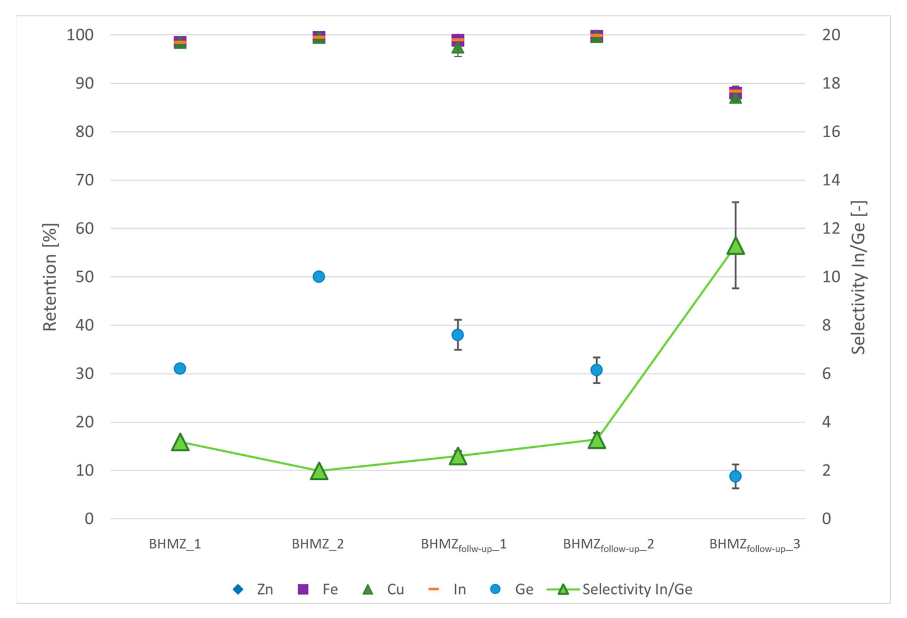
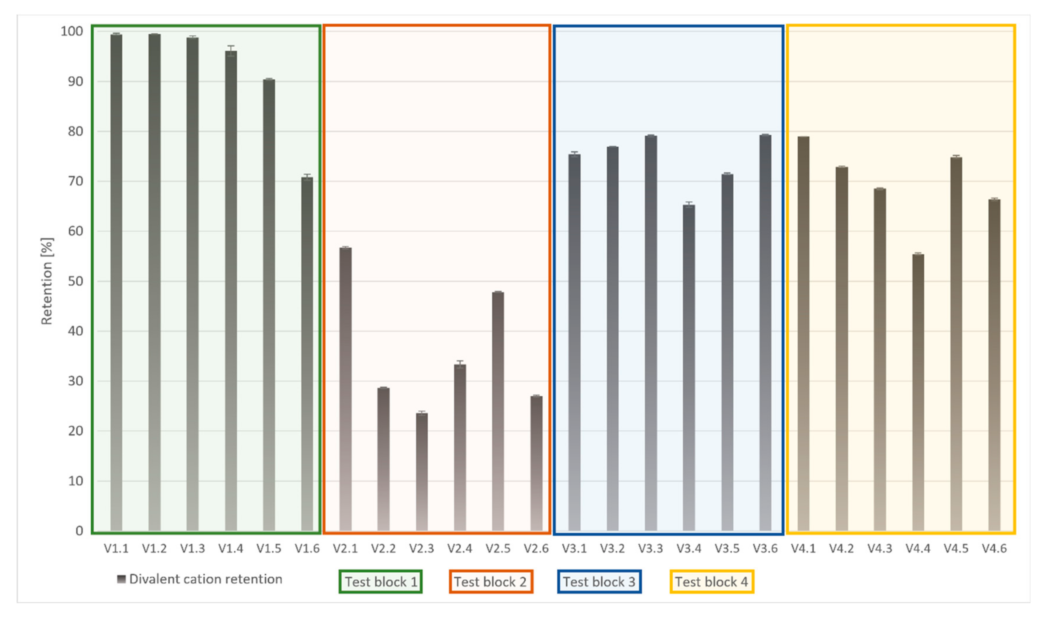
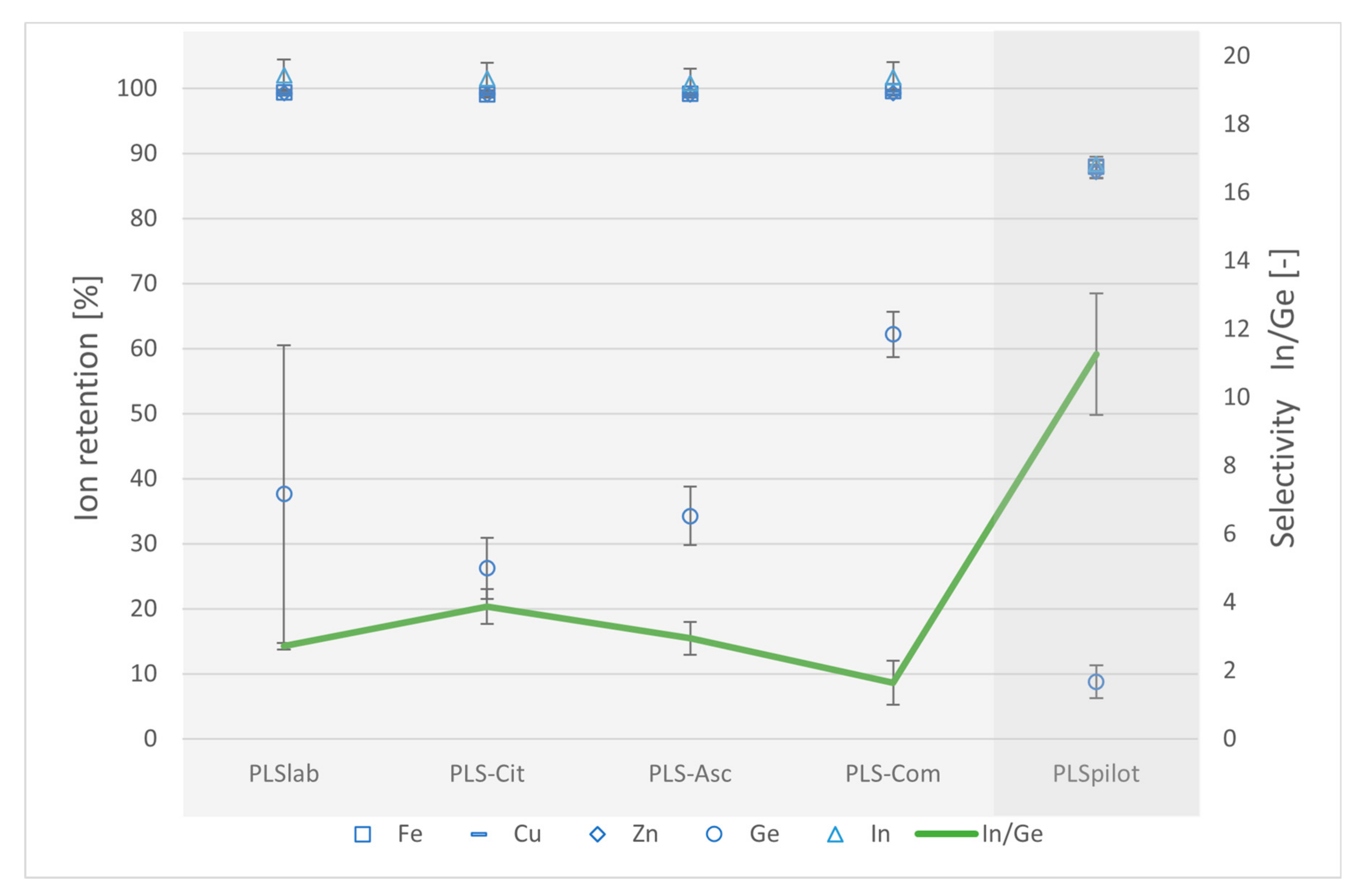
4.4.1. NF Retention, Selectivity and CIP
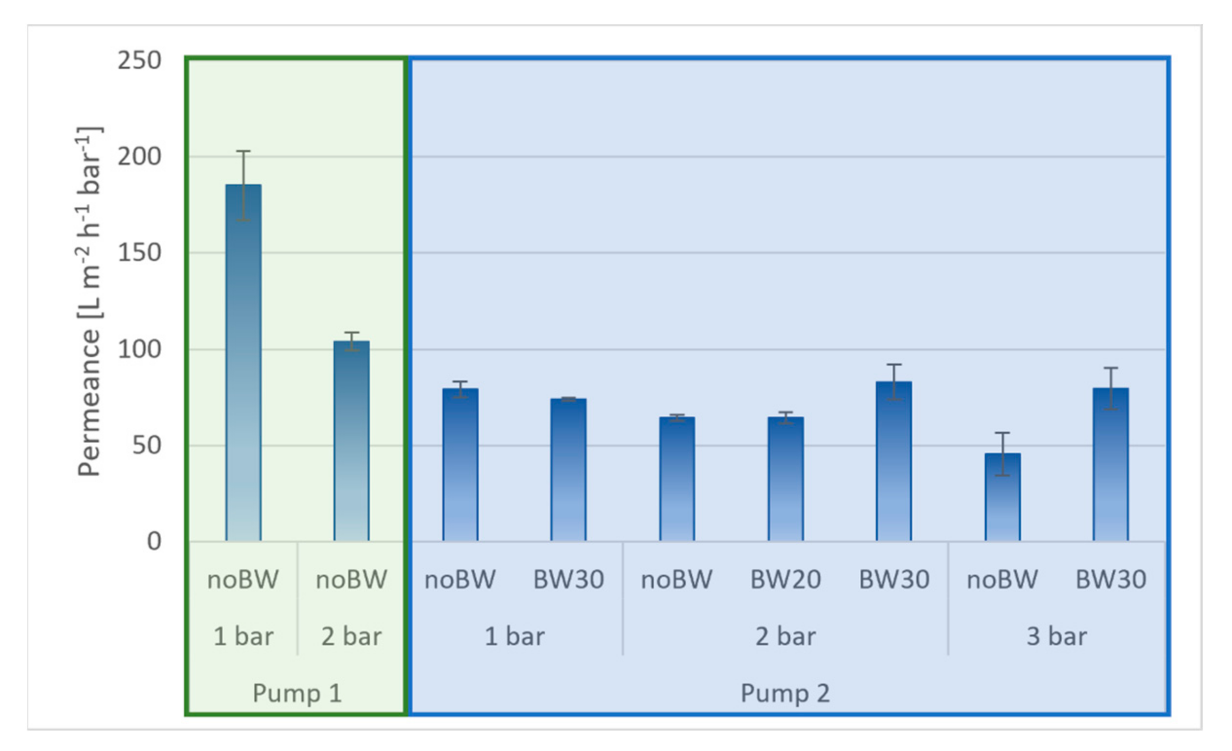
As already visualized in Section 2.4, the selective separation of indium and germanium by nanofiltration was successfully carried out thanks to comprehensive lab- and pilot-scale tests. In addition to the separation experiments, the pilot studies indicated a loss in selectivity and overall ion retention from test run to test run. Figure 11 exemplarily shows the average divalent cation retention [%] (with reference to Zn2+, Cu2+ and Fe2+) in chronological order.
As can be followed from Figure 11, divalent cation retention decreased significantly within test block 1 to test block 2, whereby each test (V1.1 to V4.6) was performed twice. Although process parameter varies slightly in terms of pressure and overflow velocity (see Table 5), cation retention decrease cannot be explained by this alone. Cation retention decline from near 100% (V1.1; V1.2) to under 25% (V2.3) was observed. Already, previous studies [32,51] proved that pressure and overflow velocity influence diffusion between solution bulk and membrane boundary layer and thus, influence factors like concentration polarization and Donnan effect. It was determined that higher overflow velocities and medium pressures result in higher retention rates. When considering the high recovery rates of 80% within the on-site pilot-scale tests at “Reiche Zeche”, additional phenomena have to be taken into account, such as fouling and scaling. Intermediate water flushing with mine tap water (MTWfiltrated—pretreated by MF and two times by NF) was performed under high overflow velocities of 1.1 m s−1, low pressures of 5 bars for about 40 min between test block 2 and test block 3 as well as between test block 3 and test block 4 and showed in the following a partially restored ion retention. Initial retention was not reached again. Thus, more suitable membrane cleaning techniques were required to reach high retention and selectivity as well as stable membrane performance under real discontinuous pilot-scale operation conditions.
CIP concerns not only the recovery of the membrane surface but also environmental issues (mining authority) as well as questions of practicability, concerning the limited storage space and transportable solution volumes (large volumes cannot be transferred underground nor used solutions up to the surface). Furthermore, there is a limitation in clean water supply, which can only be produced with great effort with the help of the membrane system itself.
Consequently, laboratory studies were conducted using real bioleaching solution. A cross-flow system [32] enabling the same process parameters, which were identified within the pilot studies as having a high selectivity towards the target elements indium and germanium (see Section 2.4—BHMZfollow-up_3, recovery rate: 25%), was used. Membrane cleaning after PLS membrane downstream processing was carried out using three different cleaning methods (overflow velocity: 1.1 m s−1, pressure: 5 bars). Results in terms of ion retention (Fe, Cu, Zn, In, Ge) and In/Ge selectivity are provided in Figure 12 in combination with additional information on the CIP method in Table 6.
Ion retention and In/Ge selectivity after PLSreal filtration and by applying different CIP methods (PLS-Cit; PLS-Asc, PLS-Com) on lab-scale are compared with the results in pilot-scale after applying CIP PLS-Cit at 80% recovery rate is shown in Figure 12.
During lab tests, nearly 100% cation retention was observed whereby Ge retention varied strongly due to the visible formation of fouling and scaling layers on the membrane surface. By applying acid–base–acid CIPs (PLS-Cit, PLS-Asc), high cation retention and low Ge retention were partially recovered and thus, selectivity between the target elements indium and germanium was obtained. Nevertheless, even by applying longer cleaning and soaking phases for the as environmentally friendly stated neutral commercial cleaning solution, the goal in terms of selectivity and retention was not reached (compare PLS-Com). To complete the nanofiltration CIP tests, citric acid cleaning method was implemented as an intermediate step to PLS downstream processing in real operation environment (PLS-Cit pilot-scale). Applying citric acid cleaning procedure showed even higher efficiency in terms of selectivity than in lab-scale. Thus, cation retention is in contrast to lab-scale just about 90%, Ge retention is below 10% and results in higher selectivity.
It can be considered that inorganic fouling and scaling on the membrane surface can be removed by acids with intermediate base cleaning for the effective removal of organics. Other studies also prove the effectiveness of this method [53,54,55,56]. Though other acids like HCl are also common and effective for CIP, citric acid is less harmful to the chloride-sensitive bioleaching microorganisms. Also, citric acid CIP meets the requirements in terms of applicability, as well as environmental requirements of the mining authority.

4.4.2. MF Fouling

Maintaining a high membrane permeance and to generally avoid membrane fouling is also set as a goal for microfiltration. Usually, fouling can be counteracted by high overflow velocities, medium pressure ranges and regular membrane cleaning [54,57,58]. For the filtration of the microbial leaching solution further requirements apply for filtration process parameters and CIP methods to avoid negative influences on microbial activity. Therefore, membrane cleaning was limited to the system-integrated permeate backwash (BW) unit. Filtration was carried out by using pump 2 (see Section 2.4) at pressure ranges between 1 and 3 bars and medium overflow velocities.
Results regarding MF permeance during the filtration of at least 200 L of biological leaching solution at recovery rates of 80% with and without intermediate BW are shown in Figure 13. Error bars indicate the average permeance decrease during filtration. Additional information on process parameters is provided in Table 5.
As can be seen in Figure 13, the filtration of the high-fouling-potential microbial leaching solution at low pressure (1 bar) and high overflow velocity (7.3 m s−1) without BW results in a high permeance loss during filtration from initial 202.9 to 167.3 L m−2 h−1 bar−1. The effect of pressure increase on fouling is well known in literature [57,59] and is also detectable by comparing the average permeance from the noBW 1 bar test to the noBW 2 bar test using pump 1 (green frame). Partly, the effect is also based on lower overflow velocity (see Table 7) resulting in lower shear forces on the membrane surface and thus, higher fouling layer formation. Taking into account the requirements of moderate process conditions to maintain microbial activity, additional tests were carried out by using pump 2 (blue-framed). The possibility of maintaining the overflow velocity at different process pressures allows to indicate the effect of pressure on fouling even clearer. Comparing MF permeance results at different overflow velocities under the same process pressures showed a significant permeance reduction at lower overflow velocities and thus, higher fouling formation. For example, medium permeance decreased at 2 bars from 104.0 to 64.4 L m−2 h−1 bar−1 due to an overflow reduction from 7.3 to 0.7 m s−1. It was found that intermediate BW after 30 min has no significant influence on MF permeance at low pressure (1 bar). On higher pressures, BW after 30 min is visibly suitable to increase permeance. BW on an interval of 20 min was found to be ineffective. Furthermore, moderate process conditions ensured the maintenance of microbial activity, evaluated on Fe2+-to-Fe3+ conversion.
To summarize, moderate process conditions for microorganisms go hand in hand with a significant MF permeance reduction, but intermediate BW after 30 min is suitable to maintain a constant membrane performance.
Further research regarding the influence of membrane filtration process parameters on microorganisms has to be carried out, evaluating microbiological activity, iron metabolism, cell growth/reduction rates and changes in the microbiological community.

5. Conclusions and Outlook

Even if the winning of critical raw materials from low-grade ores by in-situ bioleaching was stated in several studies [1,46] as having a high potential with lower environmental impacts than conventional winning methods, there is still a need for optimization, especially in terms of process adaptation to the naturally given preconditions to meet the goal of economic efficiency. Evaluating the comprehensive pilot-scale in-situ bioleaching studies of the BHMZ (TRL 6) revealed that there is a particular need for adjustment regarding the use of materials that can reliably withstand the given hard conditions of acidic dripping water, highly acidic leaching solutions and nearly 100% humidity for a long time. Furthermore, ensuring sufficient retention times within the ore body of the leaching solution in preferably all microcracks and fractures is required, despite changing conditions and the formation of preferential flow paths. For efficient bioleaching, it is also essential to ensure suitable conditions throughout the entire process, in terms of oxygen and nutrient supply. Minimizing pressure changes and shear force due to pumping was also evaluated as a major influencing factor. With regard to the two-stage (micro- and nanofiltration) on-site membrane downstream processing, it is crucial to ensure high membrane performance in terms of permeance and selectivity despite a discontinuous operation mode. All these aspects must be proven regarding practicability as well as under environmental and economic consideration. Taking these points into account, all relevant system components of the leaching cycle have been replaced with higher-alloy steels and back-pressuring valves to ensure higher retention times within the ore body. To ensure more favorable and stable conditions for the microorganisms, an on-site bioreactor was installed and the whole process of in-situ bioleaching was changed from a direct into an indirect leaching application. Process optimization results in consistently stable and faster Fe2+-to-Fe3+ conversion and thus, in higher element enrichment within a shorter time. Despite the MF process adaptation to lower overflow velocities, resulting in significant MF permeance reduction, intermediate BW at intervals of 30 min were found to be suitable to maintain the MF permeance. To ensure high continuous selectivity towards the target elements indium and germanium NF CIP methods were tested, resulting in an increased selectivity of up to 11.3 on pilot-scale.
Even if the optimization of the in-situ bioleaching cycle as well as the on-site hybrid membrane cycle can be considered a success, there is still further potential to overcome TRL 6–7 (prototype in use in real application environment for 1–5 years) and to take the next step to reach a qualified subsystem with proof of functionality in real application environment (TRL 8) [60]. For this purpose, it is necessary to transfer the system/concept to another location or at least to expand the leaching and membrane section to enable the best-achievable element enrichment and thus, economic utilization. It is also required to carry out additional detailed studies regarding the behavior and resistance of the microorganisms towards condition changes due to pumping, pressure and shear forces. Additional process automatization, remote control as well as decentralized communication and data acquisition by installing the DECOMDA system [61] is planned, minimizing time investment and personal involvement. With regard to membrane cleaning, CIP intervals must be further evaluated. Also, the membrane system should be supplemented by a further filtration step of reverse osmosis (RO) to provide concentrated and defined selective solutions to subsequent element-winning methods. As a consequence, a realistic economic evaluation would be facilitated.

Author Contributions

Conceptualization, K.G.; methodology, K.G.; validation, K.G. and R.H.; formal analysis, K.G.; investigation, K.G.; data curation, K.G.; writing—original draft preparation, K.G.; writing—review and editing, K.G., S.H., R.H. and A.S.B.; visualization, K.G.; supervision, A.S.B. and R.H.; project administration, R.H.; funding acquisition, R.H. and A.S.B. All authors have read and agreed to the published version of the manuscript.

Funding

This research was funded by the AUDI Environmental Foundation, grand number 040302084B.

Data Availability Statement

Data is contained within the article.

Acknowledgments

The authors would like to thank the mining engineers and technical staff of the Institute for Mining and Specialized Civil Engineering for the maintenance, control and optimization of the entire leaching cycle at “Reiche Zeche”, Freiberg.

Conflicts of Interest

The authors declare no conflicts of interest.

References

  1. Swain, N.; Mishra, S. A review on the recovery and separation of rare earths and transition metals from secondary resources. J. Clean. Prod. 2019, 220, 884–898. [Google Scholar] [CrossRef]
  2. Fathima, A.; Tang, J.Y.B.; Giannis, A.; Ilankoon, I.M.S.K.; Chong, M.N. Catalysing electrowinning of copper from E-waste: A critical review. Chemosphere 2022, 298, 134340. [Google Scholar] [CrossRef] [PubMed]
  3. Zarroca, M.; Roqué, C.; Linares, R.; Salminci, J.G.; Gutiérrez, F. Natural acid rock drainage in alpine catchments: A side effect of climate warming. Sci. Total Environ. 2021, 778, 146070. [Google Scholar] [CrossRef] [PubMed]
  4. Sánchez-Andrea, I.; Rodríguez, N.; Amils, R.; Sanz, J.L. Microbial Diversity in Anaerobic Sediments at Río Tinto, a Naturally Acidic Environment with a High Heavy Metal. Appl. Environ. Microbiol. 2011, 77, 6085–6093. [Google Scholar] [CrossRef] [PubMed]
  5. Enders, M.S.; Knickerbocker, C.; Titley, S.R.; Southam, G. The Role of Bacteria in the Supergene Environment of the Morenci Porphyry Copper Deposit, Greenlee County, Arizona. Econ. Geol. 2006, 101, 59–70. [Google Scholar] [CrossRef]
  6. Vera, M.; Schippers, A.; Sand, W. Progress in bioleaching: Fundamentals and mechanisms of bacterial metal sulfide oxidation—Part A. Appl. Microbiol. Biotechnol. 2013, 97, 7529–7541. [Google Scholar] [CrossRef] [PubMed]
  7. Younger, P.L.; Potter, A.B. Parys in Springtime: Hazard Management and Step towards Remediation of the UK’s Most Polluted Acidic Mine Discharge. In Proceedings of the 9th International Conference on Acid Rock Drainage (ICARD), Ottawa, ON, Canada, 20–26 May 2012; Available online: http://eprints.gla.ac.uk/69553/ (accessed on 17 December 2023).
  8. Sinclair, L.; Thompson, J. In situ leaching of copper: Challenges and future prospects. Hydrometallurgy 2015, 157, 306–324. [Google Scholar] [CrossRef]
  9. Johnson, D.B. Biomining goes underground. Nat. Geosci. 2015, 8, 165–166. [Google Scholar] [CrossRef]
  10. MacGregor, R.A. Recovery of U3O8 by Underground Leaching. CIM Bulletin. 1966. Available online: https://store.cim.org/en/recovery-of-u3o8-by-underground-leaching (accessed on 17 December 2023).
  11. Ontario Geological Survey. Ontario Mineral Inventory Record: MDI41J07NE00025. Stanrock Mine–1956. Available online: http://www.geologyontario.mndm.gov.on.ca/mndmfiles/mdi/data/records/MDI41J07NE00025.html (accessed on 17 December 2023).
  12. Statistica Research Department. Uranium Production Worldwide from 2014 to 2022, by Mining Method (in Metric Tons). Available online: https://www.statista.com/statistics/202358/world-uranium-mine-production-by-method/ (accessed on 17 December 2023).
  13. Schippers, A.; Hedrich, S.; Vasters, J.; Drobe, M.; Sand, W.; Willscher, S. Biomining: Metal recovery from ores with microorganisms. Adv. Biochem. Eng. Biotechnol. 2014, 141, 1–47. [Google Scholar] [CrossRef]
  14. Roberto, F.F.; Schippers, A. Progress in bioleaching: Part B, applications of microbial processes by the minerals industries. Appl. Microbiol. Biotechnol. 2022, 106, 5913–5928. [Google Scholar] [CrossRef]
  15. Brierley, C.L. How will biomining be applied in future? Trans. Nonferrous Met. Soc. China 2008, 18, 1302–1310. [Google Scholar] [CrossRef]
  16. Watling, H.R. The bioleaching of nickel-copper sulfides. Hydrometallurgy 2008, 91, 70–88. [Google Scholar] [CrossRef]
  17. Darling, P. SME Mining Engineering Handbook, 3rd ed.; Society for Mining Metallurgy and Exploration: Littleton, CO, USA, 2011; ISBN 978-0-87335-264-2. [Google Scholar]
  18. Henry, D. Extracting Copper from Ore in Place. Eng. Min. J. 1911, 91, 649. Available online: https://archive.org/details/sim_engineering-and-mining-journal_1911-05-27_91_21/page/1044/mode/2up (accessed on 17 December 2023).
  19. Burton, C.; Cowman, S.; Heffernan, J.; Thorne, B. In-situ bioleaching of sulphide ores at Avoca, Ireland. Part I. Development, characterization, and operation of a medium-scale (6000 t) experimental leach site. In Proceedings of the International Symposium on Biohydrometallurgy, Dublin, Ireland, 1 May 1983; pp. 213–241. [Google Scholar]
  20. Derry, R.; Whittemore, R.G. Modelling the in-situ bioleaching of zinc copper sulphide ore from Avoca, Ireland. In Proceedings of the International Symposium on Biohydrometallurgy, Dublin, Ireland, 1 May 1983; pp. 243–263. [Google Scholar]
  21. Gallagher, V.; O’Connor, P. The Avoca Mine Site. In Royal Irish Academy. Biology and Environment: Proceedings of the Royal Irish Academy; 1999; Volume 99B, No. 1 pp. 43–57. Available online: http://www.jstor.org/stable/20500045 (accessed on 17 December 2023).
  22. Noske, A. Mikrobielle Laugung von Armerzen. Deutsch-Rumänische Zusammenarbeit. Seminar 17.–18. April 1991; Berichte des Forschungszentrum Jülich: Jülich 1991; ISSN: 0366-0885. Available online: https://juser.fz-juelich.de/record/848314/files/J%C3%BCl_2504_Noske.pdf (accessed on 17 December 2023).
  23. Sand, W.; Gehrke, T. Extracellular polymeric substances mediate bioleaching/biocorrosion via interfacial processes involving iron(III) ions and acidophilic bacteria. Res. Microbiol. 2006, 157, 49–56. [Google Scholar] [CrossRef] [PubMed]
  24. Hatch Associates Ltd. BIOMOre—An Alternative Mining Concept. A New Mining Concept for Extraction Metals from Deep Ore Deposits by Using Biotechnology. D4.4 PLS Pre-Concentration, Product Recovery and Effluent Treatment. Ref. Ares(2017)1742378-31/03/2017. Available online: https://ec.europa.eu/research/participants/documents/downloadPublic?documentIds=080166e5b1693b29&appId=PPGMS (accessed on 17 December 2023).
  25. Bomberg, M.; Miettinen, H.; Wahlström, M.; Kaartinen, T.; Ahoranta, S.; Lakaniemi, A.M.; Kinnunen, P. Evaluation of Long-Term Post Process Inactivation of Bioleaching Microorganisms. SSP 2017, 262, 57–60. [Google Scholar] [CrossRef]
  26. Bomberg, M.; Miettinen, H.; Hajdu-Rahkama, R.; Lakaniemi, A.-M.; Anacki, W.; Witecki, K.; Puhakka, J.A.; Ineich, T.; Slabbert, W.; Kinnunen, P. Indirect in situ bioleaching is an emerging tool for accessing deeply buried metal reserves, but can the process be managed?—A case study of copper leaching at 1 km depth. Environ. Technol. Innov. 2023, 32, 103375. [Google Scholar] [CrossRef]
  27. Murr, L.E.; Brierley, J.A. The Use of Large-Scale Test Facilities in Studies of the role of Microorganisms in Commercial Leaching Operations. In Metallurgical Applications of Bacterial Leaching and Related Microbiological Phenomena; Murr, L.E., Torma, A.E., Brierley, J.A., Eds.; Elsevier: Amsterdam, The Netherlands, 1978; pp. 491–521. [Google Scholar] [CrossRef]
  28. Miller, P.C. Large Scale Bacterial Leaching of a Copper Zinc Ore in Situ. In Fundamental and Applied Biohydrometallurgy, Proceedings of the Sixth International Symposium of Biohydrometallurgy, Vancouver, LM, Canada, 21–24 August 1985; Lawrence, R., Branion, R., Eds.; Elsevier: Amsterdam, The Netherlands, 1986; pp. 215–239. [Google Scholar]
  29. Rossi, G.; Trois, P.; Visca, P. In-Situ Pilot Semi-Commercial Bioleaching Test at the San Valentino di Predoi Mine (Northern Italy). In Fundamental and Applied Biohydrometallurgy, Proceedings of the Sixth International Symposium of Biohydrometallurgy, Vancouver, LM, Canada, 21–24 August 1985; Lawrence, R., Branion, R., Eds.; Elsevier: Amsterdam, The Netherlands, 1986; pp. 173–189. [Google Scholar]
  30. Brauckmann, B.; Poppe, W.; Beyer, W.; Lerche, R.; Steppke, H.D. Investigations of increased biological in-situ leaching of the “Old Deposit” of Preussag Rammelsberg ore mine. In Biohydrometallurgy. Science and Technology Letters; Norris, P.R., Ed.; ACS: Kew, UK, 1988; pp. 521–523. [Google Scholar]
  31. McCready, R.G.L.; Gould, W.D. Bioleaching of uranium at Denison Mines. In Biohydrometallugry’89; Sally, J., McCready, R.G.L., Wichlacz, P.L., Eds.; CANMET Spec. Publ.: Centre for Mineral and Energy Technology: Ottawa, ON, Canada, 1989; pp. 477–483. [Google Scholar]
  32. Götze, K.; Haseneder, R.; Braeuer, A.S. Investigations on Strategic Element Recovery by an Underground Membrane Pilot Plant from In-Situ Extracted Bioleaching Solutions. Minerals 2022, 12, 46. [Google Scholar] [CrossRef]
  33. Seifert, T.; Sandmann, D. Mineralogy and geochemistry of indium-bearing polymetallic vein-type deposits: Implications for host minerals from the Freiberg district, Eastern Erzgebirge, Germany. Ore Geol. Rev. 2006, 28, 1–31. [Google Scholar] [CrossRef]
  34. Bauer, M.E.; Seifert, T. An Indium-Enriched Polymetallic Vein from Freiberg, Germany—A Perfect Site for Experimental In-Situ Bioleaching of Strategic Metals in Complex ores? In Proceedings of the Mineral Resources in a Sustainable World, SGA 13th SGA Biennial Meeting, Nacy, France, 24–27 August 2015; Volume 2. [Google Scholar]
  35. Preuß, J. Geoelektrische Bohrlochtomographie an ausgewählten Bohrlöchern im Bereich des Erzganges “Wilhelm Stehender Nord”. 2. Zwischenbericht. IFU GmbH Privates Institut für Umweltanalysen. 04. May 2018. (Internal).
  36. Schlüter, R. Bestandsaufnahme und anstehende Arbeiten am untertägigen BHMZ Versuchsstand. Oral presentation. BHMZ Arbeitsgruppentreffen. 25 April 2016. (Internal).
  37. Mischo, H.; Schlüter, R. Untersuchung von Hydraulischen und Sprengtechnischen Konditionierungsmethoden zur In-Situ Laugung im Festgestein. Conference Paper-20. Kolloquium Bohr- und Sprengtechnik; Papierflieger: Clausthal-Zellerfeld, Germany, 2017; pp. 17–27. [Google Scholar]
  38. Schlüter, R. Statusbericht Teilprojekt 2: Design, Einrichtung und Durchführung eines in-situ Versuchsstandes zur mikrobiellen Laugung im Forschungsbergwerk und Lehrbergwerk. Freiberger Biohydrometallurgisches Zentrum–BHMZ. 2018. (Internal).
  39. Krichler, T. BHMZ Zwischenbericht-Teilprojekt unter Tage. Institut für Bergbau und Spezialbergbau, TU BAF, Freiberg. 9 November 2020. (Internal).
  40. Temple, K.L.; Colmer, A.R. The autotrophic oxidation of iron by a new bacterium, thiobacillus ferrooxidans. J. Bacteriol. 1951, 62, 605–611. [Google Scholar] [CrossRef]
  41. Sharma, P. Surface characterization of Acidithiobacillus ferrooxidans cells grown under different conditions. Hydrometallurgy 2003, 71, 285–292. [Google Scholar] [CrossRef]
  42. Schippers, A. Microorganisms Involved in Bioleaching and Nucleic Acid-Based Molecular Methods for Their Identification and Quantification. In Microbial Processing of Metal Sulfides; Donati, E.R., Sand, W., Eds.; Springer: Dordrecht, The Netherlands, 2007; pp. 3–33. [Google Scholar] [CrossRef]
  43. Plumb, J.J.; Muddle, R.; Franzmann, P.D. Effect of pH on rates of iron and sulfur oxidation by bioleaching organisms. Miner. Eng. 2008, 21, 76–82. [Google Scholar] [CrossRef]
  44. Valdés, J.; Pedroso, I.; Quatrini, R.; Dodson, R.J.; Tettelin, H.; Blake, R.; Eisen, J.A.; Holmes, D.S. Acidithiobacillus ferrooxidans metabolism: From genome sequence to industrial applications. BMC Genom. 2008, 9, 597. [Google Scholar] [CrossRef] [PubMed]
  45. Johnson, D.B. Biomining-biotechnologies for extracting and recovering metals from ores and waste materials. Curr. Opin. Biotechnol. 2014, 30, 24–31. [Google Scholar] [CrossRef] [PubMed]
  46. Eisen, N.; Schlömann, M. TP6: Selectivity of microbial leaching of sphalerite in the presence of Indium and germanium. Institute of biosciences, TU BAF. Oral presentation. Holzhau, Germany. 20 May 2016. (Internal).
  47. Schopf, S. BHMZ-Teilabschlussbericht. 2nd May 2019. (internal).
  48. Schlüter, R. BHMZ-Arbeitsgruppentreffen: Bestandsaufnahme und anstehende Arbeiten am untertägigen Versuchsstand. Oral presentation. 8th May 2018. (Internal).
  49. Zhang, R.; Hedrich, S.; Ostertag-Henning, C.; Schippers, A. Effect of elevated pressure on ferric iron reduction coupled to sulfur oxidation by biomining microorganisms. Hydrometallurgy 2018, 178, 215–223. [Google Scholar] [CrossRef]
  50. Torma, A. Microbiological Extraction of Cobalt and Nickel from Sulfide Ores and Concentrates. Canadian Patent 960463, 7 January 1975. [Google Scholar]
  51. Werner, A. Entwicklung Eines Membranbasierten Trenn- und Anreicherungsverfahrens zur Selektiven Gewinnung von Indium und Germanium aus Laugungslösungen. Ph.D. Thesis, TU Bergakademie Freiberg, Freiberg, Germany, 13 August 2018. [Google Scholar] [CrossRef]
  52. Werner, A.; Haseneder, R.; Repke, J.-U. Design and Conception of a Membrane Pilot Plant for the In Situ Treatment of Bioleaching Solutions. Chem. Ing. Tech. 2019, 91, 145–150. [Google Scholar] [CrossRef]
  53. Aguiar, A.; Andrade, L.; Grossi, L.; Pires, W.; Amaral, M. Acid mine drainage treatment by nanofiltration: A study of membrane fouling, chemical cleaning, and membrane ageing. Sep. Purif. Technol. 2018, 192, 185–195. [Google Scholar] [CrossRef]
  54. Nguyen, T.; Roddick, F.A.; Fan, L. Biofouling of water treatment membranes: A review of the underlying causes, monitoring techniques and control measures. Membranes 2012, 2, 804–840. [Google Scholar] [CrossRef]
  55. Jafari, M.; Vanoppen, M.; van Agtmaal, J.M.C.; Cornelissen, E.R.; Vrouwenvelder, J.S.; Verliefde, A.; van Loosdrecht, M.C.M.; Picioreanu, C. Cost of fouling in full-scale reverse osmosis and nanofiltration installations in the Netherlands. Desalination 2021, 500, 114865. [Google Scholar] [CrossRef]
  56. Zhao, D.; Qiu, L.; Song, J.; Liu, J.; Wang, Z.; Zhu, Y.; Liu, G. Efficiencies and mechanisms of chemical cleaning agents for nanofiltration membranes used in produced wastewater desalination. Sci. Total Environ. 2019, 652, 256–266. [Google Scholar] [CrossRef]
  57. Andrade, L.H.; Aguiar, A.O.; Pires, W.L.; Grossi, L.B.; Amaral, M.C.S. Comprehensive bench- and pilot-scale investigation of NF for gold mining effluent treatment: Membrane performance and fouling control strategies. Sep. Purif. Technol. 2017, 174, 44–56. [Google Scholar] [CrossRef]
  58. Gul, A.; Hruza, J.; Yalcinkaya, F. Fouling and Chemical Cleaning of Microfiltration Membranes: A Mini-Review. Polymers 2021, 13, 846. [Google Scholar] [CrossRef]
  59. Beril Gönder, Z.; Arayici, S.; Barlas, H. Advanced treatment of pulp and paper mill wastewater by nanofiltration process: Effects of operating conditions on membrane fouling. Sep. Purif. Technol. 2011, 76, 292–302. [Google Scholar] [CrossRef]
  60. Sauser, B.; Verma, D.; Ramirez-Marquez, J.; Grove, R. From TRL to SRL: The Concept of Systems Readiness Levels. In Proceedings of the Conference on Systems Engineering Research (CSER), Los Angeles, CA, USA, 7–8 April 2006; Available online: https://citeseerx.ist.psu.edu/document?repid=rep1&type=pdf&doi=b501c19469fa5d11ada2858f310451b81b3dc61a (accessed on 17 December 2023).
  61. Krichler, T. Untersuchungen zur Echtzeitbetriebsüberwachung im Untertägigen Bergbau. Ph.D. Thesis, TU Bergakademie Freiberg, Freiberg, Germany, 9 December 2021. [Google Scholar]
Figure 1. Schematic flow sheet of the leaching cycle (step 1) and subsequent on-site membrane downstream processing (step 2), including MF (microfiltration), NF (nanofiltration) and optional RO (reverse osmosis).
Minerals 14 00308 g001
Figure 2. Bioleaching cycle. (A) Schematic setup of the bioleaching cycle at the testing site (R. Schlüter/TU BAF); (B) Close-up of the ore vein at the head road with inlet boreholes (D. Müller/TU BAF); (C) Close-up of the ore vein at the bottom road with drainage boreholes (R. Kunz/TU BAF).
Minerals 14 00308 g002
Figure 3. (A) Fe3+-rich acid mine drainage puddle containing iron and sulfur oxidizing microorganisms at the testing site (D. Müller/TU BAF); (B) Laboratory test setup for bioleaching sulfide ores from the “Reichen Zeche” using bioreactors (N. Eisen/TU BAF); (C) Setup of the first on-site leaching test trial using one inlet borehole (R. Schlüter/TU BAF); (D) On-site pilot-scale setup for direct bioleaching at the testing site with feed (front) and solution regeneration pond (back) (R. Schlüter/TU BAF).
Minerals 14 00308 g003
Figure 4. BHMZ hybrid membrane system (built by Andreas Junghans® GmbH & Co. KG, Frankenberg, Germany). (A) Planning draft with MF modules (blue framed) and NF module (yellow framed); (B) Completed membrane plant before installation at the testing site; (C) Membrane system in real operation environment.
Minerals 14 00308 g004
Figure 5. Retention [%] and In/Ge selectivity [-] development within the BHMZ and the follow-up project under adapted process parameters [32,51].
Minerals 14 00308 g005
Figure 6. Bottom road at the testing site showing (A) the ore vein “Wilhelm Stehender Nord” with drainage boreholes and (B) a close-up of one of the drainage boreholes with installed back-pressuring valve.
Minerals 14 00308 g006
Figure 7. Comparative excerpts of the first and second borehole tomography.
Minerals 14 00308 g007
Figure 8. Comparing schematic sketches of direct and indirect in-situ bioleaching.
Minerals 14 00308 g008
Figure 9. (A) Installed isolated 220 L bioreactor (right) with thermostat (left); (B) Close-up inside the bioreactor with heating coil and fine-pearled air in the bioleaching solution.
Minerals 14 00308 g009
Figure 10. Comparison of element enrichment for selected elements during in-situ bioleaching operations with logarithmic scaling. Shown are the leaching within the initial test run (light blue), during the BHMZ (blue), during the BHMZ follow-up project (dark blue), after optimization and cleaning (light green), as well as during indirect ISL (green) and indirect ISL with high pumping rate (dark green).
Minerals 14 00308 g010
Figure 11. Divalent cation retention in chronological order from test block 1 (green) to test block 2 (orange) without intermediate cleaning, and with intermediate cleaning between test block 2 and 3 (blue) as well as between test block 3 and 4 (yellow).
Minerals 14 00308 g011
Figure 12. Restored ion retention [%] and In/Ge selectivity [-] after CIP using acid–base–acid methods (PLS-Cit, PLS-Asc) and a commercial cleaning solution (PLS-Com). Light gray areas refer to lab-scale studies while dark gray areas refer to pilot-scale studies. Additional information is provided in Table 6.
Minerals 14 00308 g012
Figure 13. MF permeance under different pressure and overflow velocity conditions without intermediate backwashing (noBW) and with intermediate BW after 20 min (BW20) and 30 min (BW30).
Minerals 14 00308 g013
Table 1. Process parameters applied in the element retention and selectivity studies during the BHMZ test sections 1 and 2 (data provided by [51]) and the BHMZ follow-up project referring to test sections 1–3 (data provided by [32]).
Name_Test SectionSolutionMembranePressure
[bar]
Overflow Velocity [m s−1]Recovery Rate
[%]
Application Scale
BHMZ_1 [51]PLSsynthNF99HF15211.5lab
BHMZ_2 [51]PLSsynthNF99HF15260.0lab
BHMZfollow-up_1 [32]PLSsynthNF99HF151.2527.5lab
BHMZfollow-up_2 [32]PLSsynthNF151.2527.5lab
BHMZfollow-up_3 [32]PLSrealNF7.51.180.0pilot
Table 2. Test solution characteristics.
pHConductivityTOCTurbidityElements
SZnFeCuGeIn
(-)(mS cm−1)(mg L−1)(FNU)(mg L−1)(µg L−1)
PLSSynth.2.0 ± 0.112.7 ± 0.1<1 *02350 ± 139256 ± 78643 ± 2219 ± 1900 ± 20960 ± 30
PLSreal2.1 ± 0.210.4 ± 1.94.0 ± 0.2126.6 ± 10.62920 ± 75727 ± 49959 ± 7622 ± 270 ± 3040 ± 0
MTW4.8 ± 0.11.9 ± 0.21.1 ± 0.23.7 ± 1.2408 ± 5190 ± 81 ± 01 ± 0**
MTWfiltrated3.7 ± 0.50.4 ± 0.1<1 *-1606 ± 39 ± 31 ± 1000
* Below detection limit.
Table 3. Cleaning solution characteristics.
Concentration [vol%]Supplier
Citric acid1© VWR International, LLC, Radnor, PA, USA
Caustic soda0.1VWR International, LLC, Radnor, PA, USA
Ascorbic acid1VWR International, LLC, Radnor, PA, USA
Commercial cleaning
solution
1–2Dr. Nähring Water Treatment GmbH, Dürnau, Germany
HCl7.3VWR International, LLC, Radnor, PA, USA
Tween 200.35Merck, Darmstadt, Germany
Table 4. Process parameters of in-situ bioleaching operations at “Reiche Zeche”.
Duration [d]Inlet Pressure [bar]Initial Leaching Volume [L]Feed BoreholesPump Interval [min]Leaching Trials
Direct ISLInitial test run 21unknown171unknown1
BHMZ 152–3≈1805unknown2
BHMZ follow-up14–211≈1803–5303
Reconstruction20ca. 2≈1803301
Indirect ISLInISL7–22ca. 2200–5303302
InISLfast7ca. 2200–530332
Table 5. Process parameters for on-site NF separation tests of bioleaching solutions.
Pressure [bar]Overflow
Velocity [m s−1]
Test ID
Block 1Block 2Block 3Block 4
100.9V1.6V2.6V3.5V4.5
1.1V1.3V2.4V3.3V4.3
151V1.1; V1.5V2.1; V2.5V3.1; V3.6V4.1; V4.6
200.9V1.2V2.2V3.2V4.2
1.1V1.4V2.3V3.4V4.4
Table 6. NF CIP conditions.
MethodConcentration [Ma%]ProcedureTime of Each CIP-CyclepH [-]
Acid—base—acidCitric acid-Caustic soda-Citric acid
(PLS-Cit)
Citric acid: 1
Caustic soda: 0.05
Ascorbic acid: 1
Acid—
Clean water—
Base—
Clean water—
Acid—
Clean water
20 min plus 10 min intermediate clean water flushAcid: ~2.5
Base: 12
Ascorbic acid-Caustic soda-Ascorbic acid
(PLS-Asc)
Commercial cleanerCommercial cleaning solution
(PLS-Com)
1–2Commercial cleaner—Clean water60 to 180 min~7
Table 7. Process parameters during microfiltration tests.
PumpPressure [bar]Overflow Velocity [m s−1]Feed
117.3Microbial leaching
solution
25.7
210.7
2
3
Disclaimer/Publisher’s Note: The statements, opinions and data contained in all publications are solely those of the individual author(s) and contributor(s) and not of MDPI and/or the editor(s). MDPI and/or the editor(s) disclaim responsibility for any injury to people or property resulting from any ideas, methods, instructions or products referred to in the content.

