Article

Removal of Iron(II) as Magnetite from Acid Mine Water

by
Mokgadi Gladness Rapeta
*,
Johannes Philippus Maree
and
Titus Makudali Msagati
Institute for Nanotechnology and Water Sustainability, College of Science, Engineering and Technology, University of South Africa, Private Bag X6, Science Campus, Florida, Johannesburg 1709, South Africa
*
Author to whom correspondence should be addressed.
Minerals 2024, 14(12), 1256; https://doi.org/10.3390/min14121256
Submission received: 29 October 2024 / Revised: 5 December 2024 / Accepted: 8 December 2024 / Published: 10 December 2024
(This article belongs to the Section Environmental Mineralogy and Biogeochemistry)

Abstract

:
The High-Density Sludge (HDS) process is widely used for the treatment of acid mine water as it produces a sludge of high density. The aim of this study was the development of a process where iron in mine water can be removed as magnetite, to assist with rapid settling of sludge. It was concluded that Fe2+ can be removed as Fe3O4 (magnetite) by forming Fe(OH)2 and Fe(OH)3 in the mole ratio of 1:2. Magnetite can form in the absence or presence of gypsum. The settling rate of magnetite-rich sludge is substantially faster than that of ferric hydroxide-rich sludge. It is recommended that further studies be carried out on the separation of magnetite gypsum through magnetic separation.

1. Background

Acid mine drainage (AMD) is one of the major environmental problems in the mining industry. AMD is an acidic, metal-rich effluent that originates from the oxidative dissolution of metal sulphides in mines. When these metal sulphides are exposed to air and water, they can react to form sulphuric acid, which further accelerates the dissolution of metal sulphides and may release toxic metals. AMD is typically characterised by low pH values and high concentrations of heavy metals, which can cause serious harm to aquatic ecosystems. Iron (II) is one of the most common metals found in AMD. Iron (II) can easily be oxidised to form a precipitate of iron (III) hydroxide, which has a characteristic reddish orange colour and is known as “yellow boy” [1].
The detrimental impact of AMD on the ecosystem and infrastructure has been widely studied because of critical challenges that lie in the durability of materials exposed to acid environments. Sarmiento et al. [2] showed that AISI 1020 carbon steel and AW6060 aluminium are significantly compromised when exposed to acidic environments, and the article highlighted that both materials experience marked reductions in mechanical properties, including tensile strength and fatigue resistance. For instance, in a dynamic scenario with erosion–corrosion, the fatigue strength of carbon steel can diminish by nearly 50% after just a few days of exposure. This degradation not only affects the structural integrity of components used in mining and construction but also poses safety risks in applications like aircraft manufacturing, where material reliability is crucial [2]. Therefore, it is essential to address and remove these heavy metals from acidic environments to prevent corrosion-related failures, enhance material longevity, and minimise environmental impacts associated with metal leaching and pollution.
In the High-Density Sludge (HDS) process [3], Fe2+ is removed by raising the pH with Ca(OH)2 to 7.2, where the rate of Fe2+-oxidation is fast, and Fe3+ precipitates as Fe(OH)3. Magnetite can be recovered from iron-rich acid mine water by using Na2CO3 [4]. Fe(OH)3 can be recovered separately from gypsum by dosing scale inhibitors to keep gypsum in a solution for the period needed for sludge separation [5].
The overall chemical reaction for the formation of Fe3O4 in an aqueous medium involves the following reactants:
Dissolution of iron salts
FeSO4 → Fe2+ + SO42−
Fe2(SO4)3 → 2Fe3+ + 3SO42−
Dissolution of CaCO3 under acidic conditions
CaCO3 + H2SO4 → CaSO4 + CO2 + H2O
This reaction provides a source of CO2, which escapes as a gas under acidic conditions, and OH, which increases the pH of the solution.
Formation of Fe3O4
Under the right pH conditions, Fe2+ and Fe3+ ions react with hydroxide ions (OH) in water to form Fe3O4.
The overall reaction is as follows:
Fe2+ + 2Fe3+ + 8OH → Fe3O4 + 4H2O
Fe3O4 is a mixed-valence iron oxide with a chemical formula that can be represented as Fe[Fe2]O4, indicating the presence of both Fe(ll) and Fe(lll) ions in its structure. The formation of Fe3O4 through co-precipitation involves the simultaneous presence and precipitation of Fe(ll) and Fe(lll) ions, which ideally requires a 1:2 molar ratio of Fe2+ to Fe3+ [6].
The objective of this study was to remove Fe2+ as Fe3O4 (magnetite) through oxidation with Fe3+. The following steps were followed: (i) Determine the optimum Fe3+/Fe2+ ratio. (ii) Determine the required alkali dosage. (iii) Select the most cost-effective alkali combination. (iv) Possible separation of magnetite from gypsum. The alkalis that can be used are CaCO3, Ca(OH)2, Na2CO3 and NaOH. The calcium alkalis offer the benefit of partial desalination, which is achieved through gypsum crystallisation, while sodium alkalis result in water with high Total Dissolved Solids (TDS). The benefit of sodium alkalis is that only magnetite will form, not gypsum.

2. Literature Review

2.1. Introduction

Acid mine drainage (AMD) is rich in metals such as Fe2+/Fe3+, Al3+, Mn2+ and SO42− among other trace metals, and as such, mine water is rendered as a promising source of Fe-based minerals and sulphate. These elements can be recovered as valuable products for different applications. Magnetite (Fe3O4) is one of the commercially valuable minerals that can be synthesised by using Fe-rich salts [7].

2.2. Iron in Mine Water

2.2.1. Formation of Pyrite

Fool’s gold, or pyrite (FeS2), is a common sulphide mineral that is found in large quantities and is essential for the occurrence of acid mine drainage (AMD). A basic geochemical process known as pyrite oxidation takes place when oxygen and water are introduced to rocks that contain pyrite; this usually happens because of mining operations. Sulphuric acid (H2SO4) and dissolved iron species are produced because of this process, which has a negative effect on the environment and water quality [8].
Pyrite is oxidised by a sequence of complex chemical reactions that result in the formation of soluble and insoluble compounds from solid pyrite. The following equation can be used to summarise the entire reaction: FeS2 + 7O2 + 2H2O → 2FeSO4 + 2H2SO4.

2.2.2. Treatment Methods

Acid mine water can be effectively treated using a variety of alkalis to recover magnetite. Alkalis like lime (Ca(OH)2), limestone (CaCO3), calcium oxide (CaO), hydrated lime (Ca(OH)2), soda ash (Na2CO3) and caustic soda (NaOH) have been used to treat acid mine drainage (AMD) with promising results. These alkalis help neutralise acidic water and promote the precipitation of metals, including magnetite. By increasing the pH of the acid mine water, these alkalis help remove metals by adsorption, co-precipitation and precipitation processes [9,10].
In 1970, the Bethlehem Steel Corporation (Bethlehem, PA, USA) pioneered a way to handle effluent, known as the High-Density Sludge (HDS) process. This practice entailed combining a portion of solidified sludge materials with the discharged AMD that had been treated and adding limescale to the blended mixture. As a result of this technique, a denser sludge took form [3]. Operations under the HDS process included three stages, namely (i) pH correction/sludge monitoring, (ii) neutralisation/aeration and (iii) solid/liquid separation [11] (Figure 1).

2.3. Magnetite

The most prevalent magnetic mineral on Earth is magnetite (Fe3O4, also known as iron (II, III) oxide), which is present in sedimentary, metamorphic and igneous rocks. It is an inversed, black spinel with a well-formed octahedral crystal structure and crystalline structure. It is the most magnetic of all the natural iron oxides. An early type of magnetic compass was made of magnetite, which is found in some locations as naturally magnetised stone known as lodestone. Numerous sedimentary rocks contain magnetite, and massive amounts have been discovered in banded iron formations. Additionally, practically all igneous and metamorphic rocks include this mineral, particularly when it is present in the form of tiny grains. Magnetite- and ilmenite-rich grains that precipitate together from magma are found in many igneous rocks [13].
The ability of magnetite to be magnetic makes it the most magnetic mineral on Earth. The type and concentration of trace elements in magnetite depend on factors such as temperature, physicochemical properties, silica activity, and melt composition. Therefore, magnetite is an iron oxide composed of partially oxidised iron, with its metal component primarily made up of iron [13].

2.3.1. Chemical Reaction and Mechanisms

Iron (Fe2+) removal is a critical step in water treatment processes, especially in the context of AMD and industrial wastewater. The removal of Fe2+ can be effectively achieved through the formation of magnetite (Fe3O4), a process that involves oxidation, precipitation and crystallisation reactions. Understanding the underlying chemical mechanisms is essential for optimising this removal process, ensuring its efficiency and minimising the environmental impact of iron-laden effluent [14,15].
The initial step in the formation of magnetite involves the oxidation of Fe2+ to Fe3+. This reaction typically occurs in the presence of dissolved oxygen or other oxidising agents, such as hydrogen peroxide. The reaction is pH-dependent, with higher pH values favouring the oxidation process [8]. In aqueous solutions, Fe2+ oxidises to Fe3+ via the following reaction:
4Fe2+ + O2 + 6H2O → 4Fe(OH)3 + 8H+
The formation of Fe(OH)3 as a precipitate is crucial as it eventually leads to the formation of magnetite through further reactions. The rate of oxidation is influenced by factors such as temperature, pH and the presence of catalytic species. Once Fe3+ is formed, the next step involves the nucleation and growth of magnetite. This occurs via the interaction of Fe3⁺ and Fe2⁺ ions in a solution, typically in an alkaline environment. The reaction can be represented as follows [16]:
Fe2+ + 2Fe3+ + 8OH → Fe3O4 + 4H2O
This process is highly sensitive to pH, with the optimal formation of magnetite occurring around pH 9–11. The co-precipitation of Fe2+ and Fe3+ in this alkaline medium leads to the formation of Fe3O4 nanoparticles, which aggregate into larger magnetite particles. The kinetics of nucleation and growth depend on supersaturation levels and the presence of impurities that can either promote or inhibit the process [17].

2.3.2. Parameters Affecting Magnetite Formation

The formation of magnetite from Fe2+ and Fe3+ is highly dependent on various reaction conditions, including temperature, Fe2+ concentration, pH level and the oxidising agent.

pH Level

The pH of the solution plays a crucial role in the formation of magnetite (Fe3O4). Optimal magnetite formation generally occurs in an alkaline environment, with pH levels ranging from 9 to 11. At this pH, the co-precipitation of Fe2+ and Fe3+ leads to the formation of magnetite nanoparticles. The high pH facilitates the conversion of Fe2+ to Fe3+ and promotes the precipitation of Fe3O4. Deviations from this pH range can result in the formation of other iron oxides, such as hematite or goethite, instead of magnetite. This sensitivity to pH is attributed to the solubility of iron species and the formation kinetics in the magnetite phase [18,19].

Fe2+ Concentration

In magnetite (Fe3O4) formation, the concentration of Fe2+ plays a crucial role. Magnetite consists of both Fe2+ and Fe3+ ions, and its formation typically occurs through the oxidation of Fe2+ in aqueous solutions. A high concentration of Fe2+ can promote the formation of magnetite by providing a sufficient source of iron that can undergo oxidation and ultimately form the mixed-valence structure characteristic of magnetite. However, if the Fe2+ concentration is too high relative to Fe3+, it can lead to the formation of other iron oxide phases like hematite (Fe2O3) and goethite (HFeO2) instead of magnetite. Therefore, the Fe2+/Fe3+ ratio must be carefully controlled to favour the formation of magnetite over other iron oxide minerals [15,20].

Temperature

Temperature affects both the kinetics of magnetite formation and the characteristics of the nanoparticles. Generally, higher temperatures accelerate the nucleation and growth of magnetite, leading to faster reactions and potentially larger particles. However, excessively high temperatures can also cause the formation of unwanted by-products or lead to the aggregation of nanoparticles [21]. Temperature control is essential to optimise the size and distribution of magnetite particles, as well as to maintain consistent reaction conditions. Studies have shown that moderate temperatures typically result in better control over the size and morphology of magnetite nanoparticles [20].

Uses

Other research developments looked at the application of magnetite in other important areas, such as magnetic resonance imaging, ferro-fluids for audio speakers, magnetic targeted drug delivery, magnetic recording media and as an adsorbent in the water treatment industry.
Magnetite is used in magnetic resonance imaging (MRI) applications due to its high magnetic moment and superparamagnetic properties. Magnetite-based nano-systems can be designed to enhance the contrast in MRI images, allowing for better visualisation of tumors and other tissues. For example, magnetite nanoparticles can be functionalised with chitosan and graphene oxide to enhance their magnetic properties and improve their ability to accumulate in tumors. This allows for more accurate imaging and targeted treatment of cancer [22,23].
Nanoparticles are widely used in water treatment due to their ease of separation and reusability. They can be used as adsorbents to remove heavy metals, dyes and other contaminants from wastewater. Magnetite-based composites, such as magnetite silica nanocomposites and magnetite–graphene nanocomposites, are particularly effective in water purification. These composites can be designed to enhance the adsorption capacity and stability of magnetite, making them more effective in removing pollutants from water [24].
They are also applied in magnetic targeted drug delivery systems to enhance the delivery of anticancer drugs to specific sites in the body. Magnetite nanoparticles can be functionalised with various molecules to enhance their targeting capabilities and improve their ability to accumulate in tumors. For example, magnetite nanoparticles can be coated with polyethylene glycol and dipalmitoyl phosphatidylcholine to enhance their stability and targeting efficiency. This allows for more effective delivery of drugs to cancer cells and reduced systemic toxicity [25].
Magnetite is used in ferrofluids, which are colloidal suspensions of magnetite nanoparticles in a carrier fluid. Ferrofluids exhibit unique properties such as magnetisation and self-healing, making them useful in various applications such as magnetic storage, magnetic separation and magnetic propulsion. Magnetite ferrofluids can be designed to have specific properties such as high magnetisation, low viscosity and high stability, making them useful in a wide range of applications [24].

2.3.3. Formation

The formation of magnetite (Fe3O4) nanoparticles has drawn a lot of attention in the last few decades because of its potent magnetic characteristics and compatibility with biological systems. They are perfect for a variety of biomedical applications because of their qualities. There are up to sixteen distinct types of iron oxide, hydroxide and oxyhydroxide, which makes it difficult to synthesise iron oxide nanoparticles. However, certain methods like hydrothermal synthesis, microemulsion, thermal breakdown and coprecipitation can be used to effectively synthesise magnetite nanoparticles, which have an inverted spinel structure [26].
Magnetite nanoparticles are produced using a variety of techniques, the most common of which is chemical precipitation, which provides reasonably accurate control over the size and structure of the particles. The synthesis of magnetite by chemical precipitation involves many techniques: (1) the precipitation of Fe3+ and Fe2+ ions simultaneously, (2) partial reduction of Fe3+ ions, and (3) partial oxidation of Fe2+ ions, succeeded by simultaneous precipitation [27].
When a base is present, the aqueous coprecipitation of Fe3+ and Fe2+ ions at a 2:1 ratio to produce magnetite nanoparticles usually takes place in an anaerobic environment with a pH range of 9–12. Interestingly, the coprecipitation approach does not require precursor complexes and does not produce any hazardous intermediates or solvents. Moreover, it functions at temperatures lower than 100 °C. Its reproducibility, scalability and environmentally friendly reaction conditions are what make it significant for industry. Nevertheless, this method results in particles that vary widely in size, likely due to the complex series of reactions involved in magnetite formation.

2.3.4. Market

Due to magnetite nanoparticles’ numerous industrial applications, the market for these particles has grown significantly in recent years. These nanoparticles are widely used in biomedical areas for drug delivery, enhancing contrast in magnetic resonance imaging (MRI) and treating hyperthermia in cancer patients due to their distinct magnetic characteristics and biocompatibility. Because of their enormous surface area and reactivity, they are also essential in environmental applications, including pollutant removal and water purification [28]. Ongoing research and development, which consistently find new applications and enhance synthesis techniques, ensure the production of quality nanoparticles with regulated size and functionality and accelerate market expansion even more. As a result, it is expected that the demand for magnetite nanoparticles will increase, indicating their increasing significance for environmental sustainability and technological breakthroughs. By 2029, the market is expected to have grown to a value of 2.807 billion Rands (ZAR), with a compound yearly growth rate (CAGR) of 11.8% [29].

3. Material and Methods

3.1. Feedstock

Artificial mine water solutions containing FeSO4 (Promark chemicals, South Africa) and Fe2(SO4)3 (Promark chemicals, South Africa) were used for the formation of magnetite. NaOH, CaCO3 (Promark chemicals, South Africa) and CaO (Sigma-Aldrich, South Africa) were used as alkalis. The Fe2(SO4)3 was associated with 5.4 H2O. There is significance in computing x in Fe2(SO4)3 xH2O; hydrates are substances whose crystal structures contain molecules of water. There are several hydrates with unique properties depending on the quantity of water molecules (x) in the mixture. It is important to know the precise hydration state (value of x). Hydrates have an impact on the stoichiometry and results of chemical reactions. The specific composition of the reactants must be known for accurate calculations.
Stock solutions of 200 mmol/L of Fe2+, Fe3+ and H2SO4 (Promark chemicals, South Africa) were prepared, and 200 mL of each solution was added to conical flask and then followed by 400 mL of H2O, which was used as feed. The concentration of Fe2+ in the feed was 2289.9 mg/L and 4579.7 mg/L for Fe3+. Two alkalis were used for neutralisation, CaCO3 and CaO.

3.2. Equipment

Studies were performed in 1000 mL flat bottom conical flask at room temperature. A stirrer plate with stirrer bar was used for stirring. A hotplate was used for heat treatment of the slurry to produce magnetite at different temperatures (25, 50, 100, 200 and 300 °C). A portable pH meter was used to measure the pH of the samples during experiments.

3.3. Procedure

OLI software (Studio 11.5) simulations were used to predict the water quality when Fe2+-rich water reacted with Fe3+ by controlling the pH when dosing (i) NaOH, (ii) Ca(OH)2 and (iii) CaCO3.

3.3.1. Neutralisation

  • Preparation of the Synthetic Mine Water:
    • Amounts of 200 mL of Fe3+ solution and 200 mL of H2SO4 were mixed to achieve complete dissolution of Fe3+.
    • Amounts of 400 mL of distilled water and 200 mL of Fe2+ solutions were added to the mixture.
    • The combined solution was stirred at 250 rpm for 10 min to ensure complete mixing.
    • An amount of 50 mL of the feed solution was collected to measure the initial pH, Fe2+, Fe3+ and acidity.
  • Neutralisation with CaCO3:
    • A beaker study was conducted to measure the neutralisation rate with CaCO3.
    • An amount of 160 mmol (16 g) of CaCO3 was added to the feed solution to adjust the pH to 5.
    • The solution was allowed to settle, and the clear water was decanted to measure the pH, Fe2+, Fe3+ and acidity.
  • Neutralisation with CaO:
    • The pH was raised to 7 by adding 60 mmol (3.36 g) of CaO.
    • The slurry was stirred, and samples were taken every 30 min for 3 h to measure the pH, Fe2+, Fe3+ and acidity, as the pH continued to rise with the dissolution of CaO.
  • Magnetite Formation:
    • The de-watered slurry from the previous steps was heated at different temperatures to promote magnetite formation.

3.3.2. Gypsum Crystallisation

Preparation of Gypsum-Saturated Solution:
An amount of 4 g of CaSO4 was dissolved in 1 L of distilled water.
The solution was stirred at 250 rpm for 24 h to achieve saturation.
Gypsum/Magnetite Separation:
Single and multiple gypsum/magnetite dosages (0.5 g) were tested in 100 mL of the saturated gypsum solution.
The mixture was stirred on a magnetic stirrer for 24 h to allow for the formation of gypsum particles that can settle for better separation of magnetite and gypsum.
The Fe3O4 that was attracted to the magnet was separated and dried at 100 °C.
The mass of the dry Fe3O4 product was determined.

3.3.3. Particle Size Distribution

  • An amount of 0.5 mg of each product was added in a sample vial.
  • An amount of 1.5 mL of distilled H2O was added in a sample.
  • The solution was sonicated for 10 min at 25 °C.
  • After sonication, the upper liquid was used to measure particle size use Malvern Zetasizer Nano series.

3.3.4. Sludge Settling

  • Preparation of Solutions:
    • Solutions for settling rates of Fe(OH)3 and Fe3O4 sludge were prepared using the following concentrations: Fe2+: 4 mmol/L, Fe3+: 4 mmol/L and H2SO4: 4 mmol/L.
  • Production of Fe(OH)3 Sludge:
    • An amount of 1.60g of CaCO3 was added to 1 L of synthetic mine water, which comprised 200 mL of Fe2+ solution, 200 mL of Fe3+ solution, 200 mL of H2SO4 and 400 mL of distilled water.
    • A volume of 500 mL of this slurry was taken for further processing.
  • Flocculant Addition:
    • An amount of 10 mg/L of SEP-G-54 flocculant was added to the 500 mL slurry.
    • The mixture was rapidly stirred at 200 rpm for 30 s.
    • It was then mixed slowly at 30 rpm for 3 min.
  • Settling of Fe(OH)3 Sludge:
    • After mixing, the sludge was allowed to settle.
    • The time taken and the height of the settling process were recorded.
  • Production of Fe3O4 Sludge:
    • For the Fe3O4 sludge, 1.60 g of CaCO3 and 0.28 g of CaO were added to the same synthetic mine water solution.
    • The same procedure was followed as described above to measure the settling rate of the Fe3O4 sludge.

3.4. Experimental

The effect of Fe2+ concentration (40 mmol/L), Fe3+ concentration (40 mmol/L) and alkalis (304 mmol/L NaOH, 160 mmol/L CaCO3, 60 mmol/L CaO) were investigated using OLI simulations. Kinetic laboratory studies were also conducted that focused on sludge production at temperatures of 25, 50, 100, 200 and 300 °C; gypsum crystallisation through dosing of alkalis (instant and multiple) over 24 h; particle size of the recovered pigments; and settling studies focusing on sludge composition (Fe(OH)3/gypsum, Fe3O4/gypsum slurry) and flocculant concentration (SEP-G54).

3.5. Analytical

Samples were collected at various stages, filtered (Whatman no.1 paper-Cytiva, Marlborough, MA, USA) and assayed for Fe2+, Fe3+, pH and acidity concentrations using standard procedures [30]. Fe2+ concentrations were determined by adding filtered sample (5 mL), 0.1N H2SO4 (5 mL) and Zimmerman-Reinhardt reagent (5 mL) to an Erlenmeyer flask and titrating the solution with 0.05 N KMnO4 until pale pink [30]. Fe3+ concentrations were determined by first determining the total iron by bringing the sample (10 mL) to a pH of 0.5, and then drops of SnCl2 solution for reduction of Fe3+ to Fe2+ were added to agitate iron solution until the yellow colour disappeared, followed by one drop extra. The solution was allowed to cool for a few minutes, and then 10 mL of mercury(ll) chloride solution was quickly added, and when the precipitate was grey, a mixture of 100 mL water and 13 mL of Zimmermann-Reinhardt solution was added. The reduced sample was titrated with 0.05 N of KMnO4 until a faint pink colour was persistent for 30 s. The concentration of Fe3+ = total iron—Fe2+.
X-ray diffraction (XRD) was applied in this study where powdered samples were analysed using a PANalytical X’ Pert Pro diffractometer (Netherlands), which was run using Cu Kα radiation as the X-ray source at wavelength of 1.5406 Å. Mineral phase recognition by XRD depends on the diffraction peaks at different 2θ values relating to the mineral’s d-spacing value. According to Bragg’s Law, as each mineral has a highly ordered crystalline structure, its d-spacing values are characterised by a set of diffraction peaks [31].
Morphological and elemental properties of the synthesised pigments were elucidated using Scanning Electron Microscope (SEM) (Model: Crossbeam 340 FIB-SEM with Secondary Electron and Backscattered Electron Detectors, Carl Zeiss, Oberkochen, Germany). equipped with the means to perform Energy-dispersive X-ray spectroscopy (EDS).
Particle sizes of the nanoparticles were analysed using light scattering instrument (Model: Zetasizer Nano ZS, Malvern Panalytical, Worcestershire, UK).

3.6. OLI Software Simulations

The OLI ESP software (Studio 11.5) program was used to predict the behaviour of metals dissolved in water during dosing of alkalis, like CaCO3 and Ca(OH)2. The solubility of CaSO4 and metal hydroxides was identified as a function of temperature and concentration.
One of the most complex issues for researchers and students in the field of chemistry or advanced chemical engineering is the problems with pH calculations, solubility calculations and redox calculations. The easiest way to solve these problems is to write out the equilibrium expressions or the K equations and their corresponding equations, such as mole balance and charge balance while making simple assumptions along the way wherever useful and possible, and finally to combine the remaining equations to solve the resulting polynomial. The problems can be time-consuming even for a simple setup such as one acid in water or one dissolving salt. Environmental engineers and water engineers, among many, must deal with such problems daily in the field. For this purpose, they use various software packages ranging from simple to very detailed.
Most equilibrium modelling software packages are thought of as having two critical parts: the algorithm to solve any distinct industrial problem and the complete datasets that contain the thermodynamic constants or K values for all these problems. Additional constituents such as ionic strength corrections, adsorption equations and titration simulations, however, vary from program to program. During this study equilibrium modelling will also be used for predicting the chemical speciation during the formation of magnetite reactions.
A dependable aqueous equilibrium chemistry calculator must have an interactive and self-instructive interface for clarifying reactions, the ability to work with all kinds of common equilibrium reactions, a strong solution algorithm, expressive and easily understandable displays for results and the ability to produce results in multiple formats per different use requirements. Depending on the application it is being used for, it may be more sensible to include a database of reactions relevant to this specific purpose, specific models of complex systems or the ability to vary temperature, pressure and ionic strength. For example, the OLI Systems Analyzer that will be used in this study can perform all this with the additional option of customising every feature according to requirements and simulating them using the OLI ESP Program (11.5) [32].
The Stream Analyzer is OLI’s simplest and clearest answer to the electrolyte thermodynamic water problems of the oil and gas industry. This software features single-point equilibrium calculations, multiple-point survey calculations for calculating a complete trend analysis for characteristics like temperature, pressure, pH and composition effects, and simple mix and separate capability. The calculations provide vapour, liquid, solid and second liquid phase separations for a fully specialised model.

4. Results and Discussion

4.1. Magnetite Formation

The aim of this section was to determine the effect of the following conditions needed for magnetite (Fe3O4) formation: (i) ratio of Fe3+/Fe2+ (ii) alkali dosage (iii) O2 concentration. In addition to the mentioned aims, the following aspects will also be investigated: (i) the effect of gypsum that forms in the case of calcium alkalis (CaCO3 and CaO) and (ii) the separate recovery of Fe3O4 and CaSO4·2H2O.

4.1.1. Solubility of Fe2+ and Fe3+

This study was carried out by using FeSO4·7H2O as Fe2+ and Fe2(SO4)3·4H2O as Fe3+. Table 1 shows that 40 mmol Fe2(SO4)3·4H2O needs to be acidified with 40 mmol H2SO4 to be soluble Equation (7):
Fe2(SO4)3 + H2SO4 → 2Fe3+ + 4SO42− + 2H+

4.1.2. Removal of Fe2+ and Fe3+

Fe2+ and Fe3+ ions in mine water need to be removed as Fe(OH)3 or as Fe3O4 magnetite. The removal of Fe2+ requires oxidation to Fe3+ Equation (8) to be precipitated as Fe(OH)3 through neutralisation (Equations (9) and (10)). Alternatively, Fe2+ can be removed as Fe3O4 (magnetite) by reacting Fe(OH)2 (Equations (10) and (11)) with Fe(OH)3.
2Fe2+ + ½O2 + 2H+ → 2Fe3+ + H2O
Fe3+ + 3H2O → Fe(OH)3 + 3H+
Fe2+ + 2OH → Fe(OH)2
Fe(OH)2 + 2Fe(OH)3 → Fe3O4 + 4H2O
Iron removal needs alkali addition, such as CaCO3 (R1050/t), Ca(OH)2 (R3950/t), Na2CO3 (R10,000/t) and NaOH (R12,000/t). The use of calcium alkalis has the following benefits: (i) partial desalination is achieved through gypsum crystallisation (Equation (6)) and (ii) lower cost, as shown in brackets. Sodium alkalis have the benefit that only Fe(OH)3 is produced. A disadvantage is that the presence of sodium adds salinity to the treated water, which makes it less suitable for crop production.
Ca2+ + SO42− + 2H2O → CaSO4·2H2O
Equations (13) and (14) show the reactions for Fe3O4 and Fe(OH)3, respectively, from water containing 40 mmol/L FeSO4 and 40 mmol/L Fe2(SO4)3.
2FeSO4 + 2Fe2(SO4)3 + 16OH → 2Fe3O4 + 8SO42− + 8H2O
2FeSO4 + 2Fe2(SO4)3 + ½O2 + 16OH + H2O → 6Fe(OH)3 + 8SO42−

4.1.3. Conditions Needed for Magnetite Formation

OLI simulations were carried out to predict the effect of various parameters on the formation of Fe3O4 in a solution containing 40 mmol/L Fe2SO4, 40 mmol/L Fe(SO4)3·4H2O and 40 mmol/L H2SO4. The H2SO4 was added to keep Fe3+ in solution in the feed. The alkalis, CaCO3 and Na2CO3 were used to investigate the effect of gypsum on the formation of Fe3O4. O2 was varied to confirm that its presence will prevent the formation of Fe3O4, as Fe(OH)3 will be formed. The Fe2+/Fe3+ mole ratio was varied to identify the ratio needed for maximum Fe3O4 formation. Table 2 shows that 200 mmol Na2CO3 was needed to produce 38.34 mmol Fe3O4 at a pH of 5.16. Table 3 shows that CaCO3 was needed for the formation of 39.92 mmol Fe3O4. In the case of CaCO3, 184.6 mmol gypsum formed. OLI simulations showed that Fe3O4 forms when only carbonate is used as the alkali. Table 4 showed that the presence of O2 resulted in the formation of Fe(OH)3 and eliminated the formation of Fe3O4. Table 5 shows that the ratio of Fe2+/Fe3+ needs to be 0.5 for maximum Fe3O4 formation (40 mmol).
The findings as predicted with OLI simulations were evaluated through laboratory studies. Table 6 shows how the chemical solutions were prepared with the aim of determining the effect of alkali type and alkali dosage on the formation of Fe3O4:
  • Separate preparation of Fe(OH)3 from Fe3+ and Fe(OH)2 from Fe2+ for both Na2CO3, Ca(OH)2.
  • Separate preparation of Fe(OH)3 from Fe3+ with CaCO3 and Fe(OH)2 from Fe2+ with Ca(OH)2.
  • Sequential formation of Fe(OH)3 and Fe(OH)2 by dosing the alkali to the Fe3+/Fe2+/H+ solution.

4.1.4. Magnetite Formation in the Absence of Gypsum

Table 7 shows the results when Fe3O4 was formed from Fe(OH)3 and Fe(OH)2. Fe(OH)3 was produced from Fe2(SO4)3 and NaOH, and Fe(OH)2 was produced from FeSO4 and NaOH. All the reagents were put in the same vessel. NaOH was dosed with the aim first to raise the pH to 5.3 and to precipitate Fe3+ as Fe(OH)3, followed by dosing more NaOH to precipitate Fe2+ as Fe(OH)2 in the pH range of 7.0 to 11.1.
The following observations were made:
  • No gypsum was formed due to the absence of calcium alkalis.
  • The Fe(OH)3 and Fe(OH)2 sludge reacted to form Fe3O4 after dewatering and heated to 50 °C, 100 °C, 200 °C and 300 °C at pH 8.2 and higher. At pH 7, magnetic sludge was only produced when heated to 100 °C and higher. The combined Fe(OH)3/Fe(OH)2 sludge was not magnetic immediately after mixing, only after the sludge was dewatered and heated. The reason for this needs a special investigation.
At pH 7, when the slurry was dried at 25 °C and 50 °C, the recovered magnetite was not magnetic at this lower pH value. This was due to the absence of Fe(OH)2. It only forms after pH 7.6, as predicted by OLI simulations (Figure 2). The magnetite produced from pH 8–11 and its magnetic strength is shown in (Figure 3). It is thus concluded that the solid, Fe(OH)2, is needed as a reactant for the formation of Fe3O4.
Table 8 shows the effect of pH (8 and 11) on the formation of magnetite and goethite when Fe2+ is reacted with Fe3+ in the absence of gypsum. It was noted that magnetite formation was favoured at pH 11, while goethite was the main product at pH 8. The effect of pH on the formation of magnetite will be further investigated. The high Na2SO4 (53.0 g/L and 57.3 g/L) can be ascribed to incomplete washing of the sludge. The low gypsum concentrations should be ignored as no Ca2+ was present in the reactants.

Removal of Na2SO4 from Fe3O4

The pH of 11 was selected as the optimal value because magnetite particles formed even when the sludge was air-dried at room temperature. The magnetite recovered at pH 11 (dried at 25 and 100 °C) was thoroughly washed multiple times with deionised water by centrifuging at 4500 rpm for 10 min to ensure the complete removal of Na2SO4. The results presented below show the SEM-EDS after washing.
The micrographs of Fe3O4 (magnetite) particles, taken at 25 °C and 100 °C drying conditions in Figure 4 demonstrate notable morphological differences. At room temperature (25 °C), the magnetite exhibits a porous, aggregated structure made up of loosely packed nanoparticles. Lower magnification reveals large, irregular clusters, while higher magnification highlights the rough texture and intact porous network. Conversely, the magnetite dried at 100 °C shows a more compact and less porous structure, characterised by denser aggregates and fewer gaps between particles. At higher magnifications, partially fused nanoparticles with smoother surfaces are observed, likely a result of sintering or interparticle bonding due to the increased drying temperature. Irregular morphology is common when using precipitation [33]. The SEM/EDS shows that Na2SO4 was completely washed off. The C present was from the carbon paper that was used. The recovered magnetite at pH 11 indicates a nanoscale material with a particle size of 143.6 d.nm, as shown in Figure 5.

4.1.5. Fe3O4/Fe2O3 Formation in the Presence of Gypsum

CaCO3 as the Alkali

OLI simulations indicated that only CaCO3 is needed for the formation of magnetite (Fe3O4) from Fe2+ and Fe3+. Table 9 showed that when CaCO3 is used as the alkali for the treatment of a solution that contained Fe2(SO4)3, FeSO4 and H2SO4, only Fe2O3 formed, and no Fe3O4. The CaCO3 dosage was sufficient to neutralise the H2SO4 and precipitate Fe3+ as Fe(OH)3 and Fe2+ as Fe(OH)2. Strict conditions were created to prevent Fe2+ oxidation. The presence of O2 was eliminated by closing the 1 L conical flask with parafilm and by putting the flask in a 5 L nitrogen filled beaker. Gypsum was formed due to the presence of calcium alkalis. The settled Fe(OH)3 and CaSO4·2H2O sludge was stirred for 10 min at room temperature, dewatered and heated to 50 °C, 100 °C, 200 °C and 300 °C. Fe3O4 (magnetite) can only be formed when Fe(OH)2 is formed and when Ca(OH)2 is dosed. Only CaCO3 could not result in Fe3O4 formation as it cannot produce the essential Fe(OH)2 when the pH is raised to 7.6 and higher, as shown in Figure 2. This finding is in contradiction to that predicted by OLI simulations.
Figure 6 showed that upon heating, the colour changed to yellow at 100 °C, which is an indication of goethite formation, and to red at 300 °C, which is an indication of hematite formation. Table 10 shows the effect of temperature (100 °C and 300 °C) on the chemical composition of the sludge. Goethite was the main ion compound at 100 °C (11.3%) and hematite at 300 °C (6.1%). It was noted that at 100 °C, the CaSO4 was only present as bassanite, while at 300 °C, it appeared as bassanite (HCaSO4) and anhydrite (CaSO4). The SEM images in Figure 7 of goethite and hematite containing gypsum reveal rough, textured surfaces typical of their crystalline structures, shaped by the presence of gypsum. In the case of goethite, the interaction with gypsum encourages agglomeration, creating irregular porous features, different degrees of particle clustering and possible gypsum intercalation within the goethite matrix, resulting in layered structures or voids. Likewise, for hematite, the interaction with gypsum promotes particle aggregation, resulting in clusters, layered or porous formations and a diverse range of particle sizes, including both larger aggregates and smaller particles. The XRD spectra in Figure 8 and Figure 9 confirmed the presence of goethite and hematite with good crystallinity.

CaCO3 and CaO as the Alkali

Table 11 shows that the CaCO3 dosage was sufficient to neutralise the H2SO4, precipitate Fe3+ as Fe(OH)3 and CaO to precipitate Fe2+ as Fe(OH)2. Gypsum was formed due to the presence of Ca2+. The settled Fe(OH)3, Fe(OH)2 and CaSO4·2H2O sludge was stirred for 10 min at room temperature, dewatered and heated to 50 °C, 100 °C, 200 °C and 300 °C. The Fe(OH)3/Fe(OH)2/CaSO4·2H2O sludge was not magnetic immediately after mixing, only after the sludge was dewatered and heated. Table 12 shows the results of when Fe3O4 was formed from a solution that contained Fe2(SO4)3, FeSO4 and H2SO4 when treated with CaO. Table 13 show the sludge composition after heating to 100 °C. It was shown that the iron was magnetite (6.7% and 6.5%) with no other iron compounds present. The amount of magnetite formed was not affected by instant or multiple dosing. The question is whether it has an influence on magnetic separation.
The micrographs of Fe3O4 (magnetite) particles for both instant and multiple dosing, as shown in Figure 10, reveal clear morphological variations between instant and multiple alkali dosing methods. Instant dosing produces a compact structure with densely packed aggregates and larger clusters, whereas multiple dosing results in a more varied morphology, featuring finer gypsum crystals and a broader range of particle sizes. These observations emphasise the significant influence of dosing techniques on the properties of the magnetite–gypsum composite. Irregular morphology is common when using the precipitation method [33]. Gypsum showed a more elongated, fibrous and needle-like morphology, which is consistent with its natural tendency to form acicular (needle-shaped) or prismatic crystals [34,35].
The XRD results in Figure 11 and Figure 12 show the presence of characteristic magnetite peaks. The use of CaCO3 and CaO provided a favourable environment for the precipitation of magnetite from the Fe2+/Fe3+ solution. The most prominent peaks for magnetite appear around 35° (2θ = 35.076°), and other peaks at 41.385°, 50.448°, 67.228° and 74.124°. These peaks are associated with the characteristic reflections of magnetite. The presence of gypsum and anhydrite compounds was the result of crystallisation as its solubility level was exceeded. The recovered magnetite was highly crystalline, as indicated by the sharp and intense peaks. The presence of other crystalline phases, such as gypsum, calcite and anhydrite, pointed to a well-ordered crystal structure for these byproducts. This confirms that these alkalis can be effective for the recovery of magnetite, with the byproducts being stable calcium sulphate minerals.

Importance of Hydroxide in Fe3O4 Formation

The hydroxide ion (OH) is pivotal in the formation of magnetite (Fe3O4) from iron salts, influencing the entire synthesis process from nucleation to the final properties of the nanoparticles. One of the primary roles of OH is in controlling the pH of the reaction medium. The pH determines the speciation of iron ions and the subsequent precipitation of iron hydroxides. In a basic environment, OH ions react with Fe2+ and Fe3+ ions to form Fe(OH)2 and Fe(OH)3, which are precursors to magnetite. The optimal pH for magnetite formation is typically between 8 and 11. At this pH range, the solubility of iron hydroxides decreases, facilitating their precipitation and subsequent transformation into magnetite through a series of redox reactions [36,37].
Beyond pH control, OH ions directly influence the nucleation and growth of magnetite nanoparticles. A higher concentration of OH ions accelerates the nucleation process, leading to the formation of numerous small nuclei, which then grow into nanoparticles. The availability of OH ensures a consistent supply of reactants for these nucleation sites, promoting uniform particle size and morphology. Conversely, insufficient OH can result in incomplete precipitation and the formation of iron oxides other than magnetite, such as goethite or lepidocrocite, which have different magnetic properties [13,38].
OH ions played a crucial role in maintaining the stoichiometry and crystallinity of magnetite. The balance between Fe2+ and Fe3+ in the presence of OH ions is essential for forming the mixed-valence compound Fe3O4. An optimal OH concentration ensures that the redox reactions proceed correctly, leading to the formation of stoichiometric magnetite. Moreover, OH ions help in achieving high crystallinity by providing the necessary conditions for the ordered arrangement of iron and oxygen atoms in the crystal lattice. High crystallinity is directly related to better magnetic properties, as it reduces defects and enhances magnetic domain alignment [13].
Finally, OH ions aid in the removal of impurities and by-products during the synthesis process. During the formation of magnetite, various side reactions can occur, producing soluble by-products. OH ions can help in precipitating these impurities, which can then be removed through washing. This purification step is crucial for obtaining pure magnetite with desired magnetic properties. In summary, the role of OH ions in magnetite synthesis is multifaceted, encompassing pH control, nucleation and growth regulation; stoichiometry and crystallinity maintenance; and impurity removal, all of which are critical for producing high-quality magnetite nanoparticles [38].

4.2. Separation of Magnetite and Gypsum

When calcium alkalis are used for the neutralisation of mine water, rich in sulphate, gypsum co-precipitates with iron hydroxides. The purpose of this investigation was to recover the magnetite separately from gypsum through magnetic separation. It was argued that large gypsum crystals will favour the magnetic separation of the two compounds. Gypsum of small-sized particles was produced by dosing the calcium alkali in a single dosage. Gypsum with particles with large sizes was produced by dosing the calcium alkali in splitting the dosage in a number of small dosages over time. Iron-rich water (40 mmol/L FeSO4, 40 mmol/L Fe2(SO4)3, 40 mmol/L H2SO4) was neutralised with 160 mol/L CaCO3 followed by 40 mmol/L Ca(OH)2. In the case of a single dosage, the CaCO3 was dosed at time 0 and the Ca(OH)2 after 30 min. Samples were collected over a period of 180 min and analysed for pH, Fe2+ and acidity. In the case of multiple dosages, the CaCO3 and CaO were split in four and dosed after 0, 30, 60 and 90 min. The CaCO3 dosing was carried out first for the removal of Fe3+ as Fe(OH)3, followed by CaO dosing for the removal of Fe2+ as Fe(OH)2. Table 14 shows how Fe2+ and acidity were removed as CaCO3 and CaO were dosed for the two dosing methods. It was noticed that the gypsum particle size in the case of multiple dosing was larger than in the case of a single dosage. That was due to the growth of larger crystals at lower levels of over-saturation in the case of multiple dosages.
The single and multiple gypsum/magnetite dosages (0.5 g) were tested for separation by placing them in a 100 mL saturated gypsum solution to avoid dissolution of the gypsum component (Table 15). A magnet was used to attract the Fe3O4. The mass was determined and analysed with XRD for the solid species on the magnet. Table 16 shows that more magnetite was attracted by the magnet in the case of multiple dosages (11.7%) than in the case of single doses (6.5%). This can be ascribed to larger gypsum particles that formed in the case of multiple dosing and that settled. This aspect should be further investigated as it may have the potential for full-scale application if a good separation is achieved. The focus is now on the production of magnetite-rich sludge and its settling.
The particle size of the products was measured as shown in Figure 13, and the presence of gypsum in the magnetite sample had a significant impact on particle size measurements, yielding Z-average values of 1588 d.nm (PDI 0.377) for instant dosing and 2064 d.nm (PDI 0.422) for multiple dosing, which indicate a polydisperse system. Gypsum promotes particle aggregation by connecting magnetite particles or modifying surface stability. XRD analysis showed a decrease in gypsum intensity after multiple dosing treatment and an increase after instant dosing, aligning with reduced particle sizes of 1404 d.nm (multiple dosing) and increased 2823 d.nm (instant dosing). The gradual addition of alkalis during multiple dosing resulted in the formation of large gypsum crystals that remained after heat treatment. During saturated gypsum treatment, these crystals settled at the bottom, separating from the magnetite during the recovery process.

4.3. Settling Studies

Fe(OH)3 sludge settled slowly. The High-Density Sludge (HDS) process was developed to produce a sludge that settles at a fast rate. Lime was used in the HDS process to condition the sludge at pH 12. The conditioned sludge was then contacted with the AMD to form High-Density Sludge. The focus of this investigation was to compare the settling rate of magnetite-rich sludge, as described in the previous sections, with the settling rate of Fe(OH)3-rich sludge. Fe3O4 and Fe(OH)3-rich sludges were prepared as calculated in Table 17. Settling was supported by dosing 10 mg/L SEP-G-54 flocculant to the waters with the sludge. After dosing with the flocculant, rapid stirring (200 rpm) was applied for 30 s, followed by slow mixing (30 rpm) for 3 min and sludge settling. Table 18 and Table 19 show the settling rate of Fe3O4/gypsum and Fe(OH)3/gypsum-rich sludges. It was noted from Figure 14, Table 18 and Table 19 that the Fe3O4/gypsum sludge settled faster than the Fe(OH)3/gypsum, namely 0.80 m/h versus 0.21 m/h. This can be ascribed to the higher density of Fe3O4 particles compared to Fe(OH)3 particles and the formation of larger aggregates. In terms of hydration, Fe(OH)3 is more hydrated and has a higher water content, making the particles less dense and more difficult to settle. This hydration slows down the settling process compared to Fe3O4 particles. Figure 15 shows the settled sludge for Fe(OH)3 and Fe3O4-rich sludge.

4.4. Novelty

The novelty of the removal of iron from iron-rich mine water lies in the removal of the Fe2+ portion without the need to oxidise it to Fe3+, as is the case with the HDS process. Another novel aspect is the higher settling rate of the magnetite-rich sludge.

5. Conclusions and Recommendations

The following conclusions were made from this study: (i) Fe2+ can be removed as Fe3O4 (magnetite) by forming Fe(OH)2 and Fe(OH)3 in the mole ratio of 1:2 by precipitating Fe3+ with a carbonate or a hydroxide and by precipitating Fe2+ as a hydroxide, (ii) magnetite can form in the absence or presence of gypsum, (iii) the settling rate of magnetite-rich sludge is substantially faster than that of ferric hydroxide-rich sludge and (iv) separate recovery of magnetite and gypsum may be possible after further investigations. It is recommended that the following aspects be further investigated due to their practical value: (i) the effect of pH on magnetite formation, (ii) sludge settling and (iii) the separation of magnetite from gypsum through magnetic separation.
The optimal parameters for the recovery of magnetite involve using nitrogen gas to prevent the oxidation of Fe2+ to Fe3+ in solution. A stirring rate of 250 rpm effectively balanced particle dispersion. When NaOH was used as an alkali, optimal conditions were achieved at a pH of 11 and a temperature of 25 °C and NaOH (304.4 mmol/L). For instant and multiple dosing, the ideal conditions are a pH of 7.2 and a temperature of 100 °C, along with concentrations of CaCO3 (160 mmol/L) and CaO (60 mmol/L). The Fe2+ removal rate for instant and multiple dosing was found to be 88.4% and 90.7%, respectively, while for NaOH it was found to be 97.6%. All methods demonstrate high Fe2+ removal rates, showcasing their effectiveness in treatment processes.

Author Contributions

Conceptualisation, Data Curation, Formal Analysis, Investigation, Methodology, Software, Writing—original draft: M.G.R.; Data Curation, Formal Analysis, Funding Acquisition, Investigation, Methodology, Resources, Software, Supervision, Validation, Writing—review and editing: J.P.M. Writing—review and editing, Validation, Investigation, Resources: T.M.M. All authors have read and agreed to the published version of the manuscript.

Funding

This work is based on research supported by the Department of Trade and Industry (DTI) under the Technology and Human Resources for Industry Programme (THRIP/23/04/05/2023) through ROC Water Technologies, Mamdiwas (02WAS1719A) and National Intellectual Property Management Office (NIPMO) who sponsored the grant for the innovation award of 2021 NSTF-South32, which was received by ROC Water Technologies.

Data Availability Statement

The raw/processed data required to produce these findings cannot be shared at this time as the data also forms part of an ongoing study.

Acknowledgments

The authors express their gratitude to THRIP, Mamdiwas and the University of South Africa (UNISA) Institute of Nanotechnology and Water Sustainability for providing us with research facilities. Kagiso More is thanked for proofreading and editorial and language input. We also thank Mxolisi Motsa and Anele Tshaka for assisting with SEM analysis.

Conflicts of Interest

The authors declare that they have no competing interests.

References

  1. McCarthy, T.S. The Impact of Acid Mine Drainage in South Africa. S. Afr. J. Sci. 2011, 107, 5–6. [Google Scholar] [CrossRef]
  2. Sarmiento, A.M.; Rodriguez-Perez, A.M.; Davila, J.M.; de la Torre, M.L. Effect of acid mine drainage on the mechanical properties of AISI 1020 carbon steel and AW6060 aluminium. J. Mater. Res. Technol. 2024, 32, 541–549. [Google Scholar] [CrossRef]
  3. Kostanbader, P.D.; Haines, G.F. High Density Sludge Treats Acid Mine Drainage. Coal Age 1970, 75, 90–97. [Google Scholar]
  4. Akinwekomi, V. Formation of Magnetite During Desalination of Acid Mine Drainage. 1-225. Ph.D. Thesis, Department of Environmental, Water & Earth Sciences, Faculty of Sciences, Tshwane University of Technology, Pretoria, South Africa, 2017. [Google Scholar]
  5. Mogashane, T.M.; Maree, J.P.; Mujuru, M.; Mphahlele-Makgwane, M.M.; Modibane, K.D. Ferric Hydroxide Recovery from Iron-Rich Acid Minewater with Calcium Carbonate and a Gypsum Scale Inhibitor. Minerals 2023, 13, 167. [Google Scholar] [CrossRef]
  6. Cornell, R.M.; Schwertmann, U. The Iron Oxides: Structure, Properties, Reactions, Occurrences, and Uses; Wiley: New York, NY, USA, 2003; Volume 664. [Google Scholar] [CrossRef]
  7. Gitari, W.M.; Petrik, L.F.; Akinyemi, S.A. Treatment of acid mine drainage with coal fly ash: Exploring the solution chemistry and product water quality. In Coal Fly Ash Beneficiation: Treatment of Acid Mine Drainage with Coal Fly Ash; IntechOpen: London, UK, 2018; pp. 79–99. [Google Scholar]
  8. Thiel, J.; Byrne, J.M.; Kappler, A.; Schink, B.; Pester, M. Pyrite Formation from Fes and H2s Is Mediated through Microbial Redox Activity. Proc. Natl. Acad. Sci. USA 2019, 116, 6897–6902. [Google Scholar] [CrossRef]
  9. Baloyi, J.; Ramdhani, N.; Mbhele, R.; Ramutshatsha-Makhwedzha, D. Recent Progress on Acid Mine Drainage Technological Trends in South Africa: Prevention, Treatment, and Resource Recovery. Water 2023, 15, 3453. [Google Scholar] [CrossRef]
  10. Zhao, P.; Zhang, R.; Hu, M. Alkaline Chemical Neutralization to Treat Acid Mine Drainage with High Concentrations of Iron and Manganese. Water 2024, 16, 821. [Google Scholar] [CrossRef]
  11. Dama-Fakir, P.; Sithole, Z.; Van Niekerk, A.M.; Dateling, J.; Maree, J.P.; Rukuni, T.; Mthombeni, T.; Ruto, S.; Zikalala, N.; Hughes, C. Mine Water Treatment Technology Selection Tool: Users’ Guide; Water Research Commission: Pretoria, South Africa, 2017. [Google Scholar]
  12. Osuchowski, R. Advanced Treatment of Acid Mine Water; Technology SA: Pretoria, South Africa, 1992; pp. 9–11. [Google Scholar]
  13. Nguyen, M.D.; Tran, H.V.; Xu, S.; Lee, T.R. Fe3O4 nanoparticles: Structures, synthesis, magnetic properties, surface functionalization, and emerging applications. Appl. Sci. 2021, 11, 11301. [Google Scholar] [CrossRef]
  14. Navratil, J.D.; Akin, A.C. Mine Water Treatment Using Iron Ferrites and Magnetite. In Proceedings of the International Mine Water Conference, Pretoria, South Africa, 19–23 October 2009. [Google Scholar]
  15. Roonasi, P.; Holmgren, A. A Study on the Mechanism of Magnetite Formation Based on Iron Isotope Fractionation. In Proceedings of the TMS 2009 Annual Meeting and Exhibition, San Francisco, CA, USA, 15–19 February 2009. [Google Scholar]
  16. Niculescu, A.G.; Chircov, C.; Grumezescu, A.M. Magnetite Nanoparticles: Synthesis Methods—A Comparative Review. Methods 2022, 199, 16–27. [Google Scholar] [CrossRef]
  17. Mascolo, M.C.; Pei, Y.; Ring, T.A. Room Temperature Co-Precipitation Synthesis of Magnetite Nanoparticles in a Large Ph Window with Different Bases. Materials 2013, 6, 5549–5567. [Google Scholar] [CrossRef]
  18. Suppiah, D.D.; Johan, M.R. Influence of Solution Ph on the Formation of Iron Oxide Nanoparticles. Mater. Res. Express 2018, 6, 015008. [Google Scholar] [CrossRef]
  19. Darminto; Cholishoh, M.N.; Perdana, F.A.; Baqiya, M.A.; Mashuri Cahyono, Y.; Triwikantoro. Preparing Fe3O4 Nanoparticles from Fe2+ Ions Source by Co-Precipitation Process in Various pH. AIP Conf. Proc. 2011, 1415, 234–237. [Google Scholar]
  20. Li, Z.; Chanéac, C.; Berger, G.; Delaunay, S.; Graff, A.; Lefèvre, G. Mechanism and Kinetics of Magnetite Oxidation under Hydrothermal Conditions. RSC Adv. 2019, 9, 33633–33642. [Google Scholar] [CrossRef] [PubMed]
  21. Gutierrez, F.V.; Lima, I.S.; De Falco, A.; Ereias, B.M.; Baffa, O.; de Abreu Lima, C.D.; Sinimbu, L.I.; de la Presa, P.; Luz-Lima, C.; Araujo, J.F. The Effect of Temperature on the Synthesis of Magnetite Nanoparticles by the Coprecipitation Method. Heliyon 2024, 10, e25781. [Google Scholar] [CrossRef] [PubMed]
  22. Ünak, P. Imaging and Therapy with Radionuclide Labeled Magnetic Nanoparticles. Braz. Arch. Biol. Technol. 2008, 51, 31–37. [Google Scholar] [CrossRef]
  23. Stephen, Z.R.; Kievit, F.M.; Zhang, M. Magnetite Nanoparticles for Medical Mr Imaging. Mater. Today 2011, 14, 330–338. [Google Scholar] [CrossRef]
  24. Jain, R. Recent Advances of Magnetite Nanomaterials to Remove Arsenic from Water. RSC Adv. 2022, 12, 32197–32209. [Google Scholar] [CrossRef]
  25. Kurczewska, J.; Dobosz, B. Recent Progress and Challenges Regarding Magnetite-Based Nanoparticles for Targeted Drug Delivery. Appl. Sci. 2024, 14, 1132. [Google Scholar] [CrossRef]
  26. Ahn, T.; Kim, J.H.; Yang, H.M.; Lee, J.W.; Kim, J.D. Formation Pathways of Magnetite Nanoparticles by Coprecipitation Method. J. Phys. Chem. C 2012, 116, 6069–6076. [Google Scholar] [CrossRef]
  27. Wei, X.; Viadero, R.C., Jr. Synthesis of Magnetite Nanoparticles with Ferric Iron Recovered from Acid Mine Drainage: Implications for Environmental Engineering. Colloids Surf. A Physicochem. Eng. Asp. 2007, 294, 280–286. [Google Scholar] [CrossRef]
  28. Rao, M.S.; Rao, C.S.; Kumari, A.S. Synthesis, Stability, and Emission Analysis of Magnetite Nanoparticle-Based Biofuels. J. Eng. Appl. Sci. 2022, 69, 79. [Google Scholar] [CrossRef]
  29. Prabowo, B.; Khairunnisa, T.; Nandiyanto, A.B. Economic Perspective in the Production of Magnetite (Fe3O4) Nanoparticles by Co-Precipitation Method. World Chem. Eng. J. 2018, 2, 1–4. [Google Scholar]
  30. APHA. Standard Methods for the Examination of Water and Wastewater (American Public Health Association); American Water Works Association, Water Environment Federation: Washington, DC, USA, 2012. [Google Scholar]
  31. Shirin, S.; Yadav, A.K. Evaluation of Acid Mine Water Body Water Quality Treatment with Fly Ash. Environ. Chall. 2021, 4, 1–17. [Google Scholar]
  32. OLI. Electrolyte Simulation Software Tools. OLI. Available online: http://www.olisystems.com/ (accessed on 23 November 2015).
  33. Dudchenko, N.; Pawar, S.; Perelshtein, I.; Fixler, D. Magnetite Nanoparticles: Synthesis and Applications in Optics and Nanophotonics. Materials 2022, 15, 2601. [Google Scholar] [CrossRef] [PubMed]
  34. Mahmoud, M.H.; Rashad, M.M.; Ibrahim, I.A.; Abdel-Aal, E.A. Crystal Modification of Calcium Sulfate Dihydrate in the Presence of Some Surface-Active Agents. J. Colloid Interface Sci. 2004, 270, 99–105. [Google Scholar] [CrossRef]
  35. Cheng, P.; Chen, D.; Liu, H.; Zou, X.; Zhang, Y.; Xie, J.; Qing, C.; Chen, T. Enhanced Adsorption Capacity for Phosphate in Wastewater from Thermally Activated Flue Gas Desulfurization Gypsum. J. Chem. Technol. Biotechnol. 2018, 93, 1733–1741. [Google Scholar] [CrossRef]
  36. Ba-Abbad, M.M.; Benamour, A.; Ewis, D.; Mohammad, A.W.; Mahmoudi, E. Synthesis of Fe3O4 Nanoparticles with Different Shapes through a Co-Precipitation Method and Their Application. JOM 2022, 74, 3531–3539. [Google Scholar] [CrossRef]
  37. Trifoi, A.R.; Matei, E.; Râpă, M.; Berbecaru, A.C.; Panaitescu, C.; Banu, I.; Doukeh, R. Coprecipitation Nanoarchitectonics for the Synthesis of Magnetite: A Review of Mechanism and Characterization. React. Kinet. Mech. Catal. 2023, 136, 2835–2874. [Google Scholar] [CrossRef]
  38. Al-Madhagi, H.; Yazbik, V.; Abdelwahed, W.; Alchab, L. Magnetite Nanoparticle Co-Precipitation Synthesis, Characterization, and Applications: Mini Review. Bionanoscience 2023, 13, 853–859. [Google Scholar] [CrossRef]
Figure 1. 
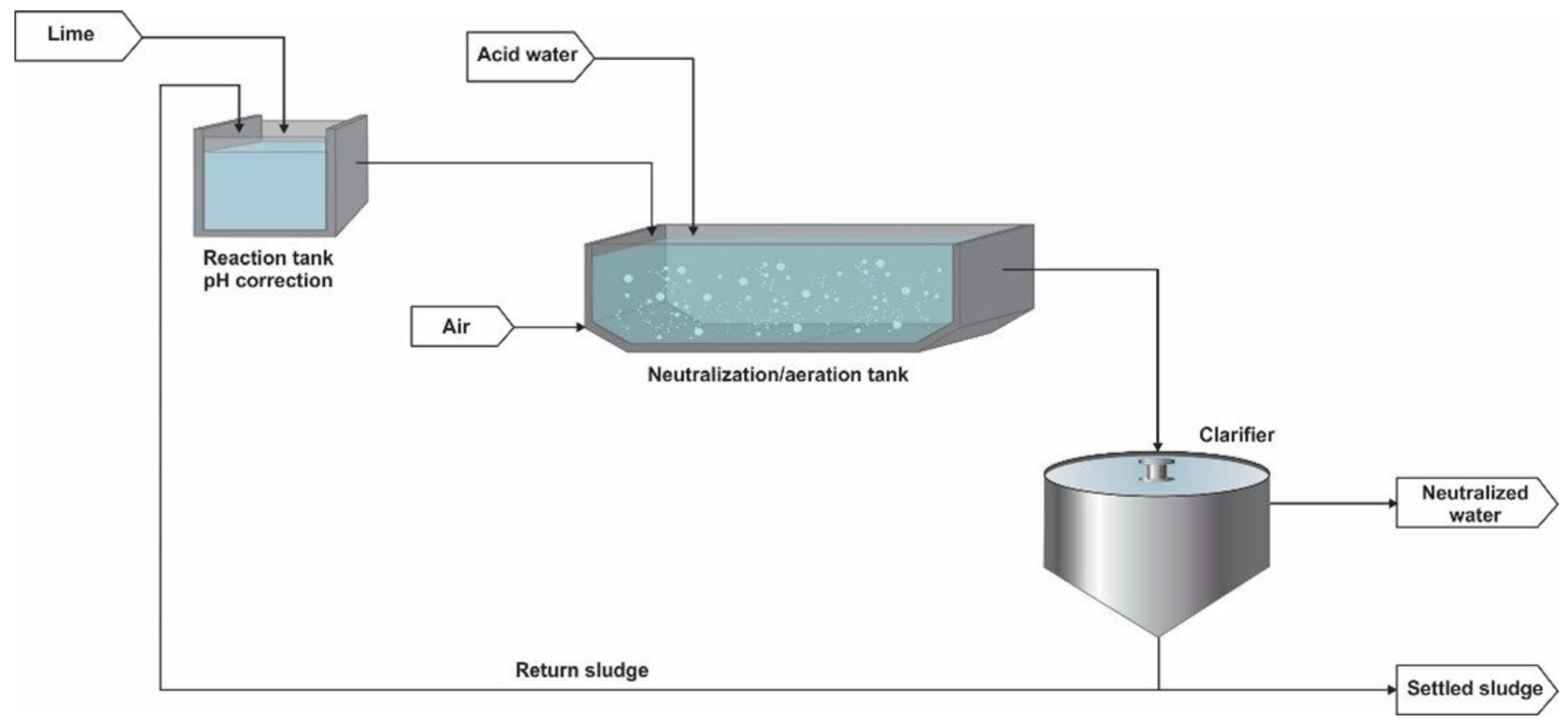
Neutralisation process of High-Density Sludge for AMD treatment [3,12].
Minerals 14 01256 g001
Figure 2. 
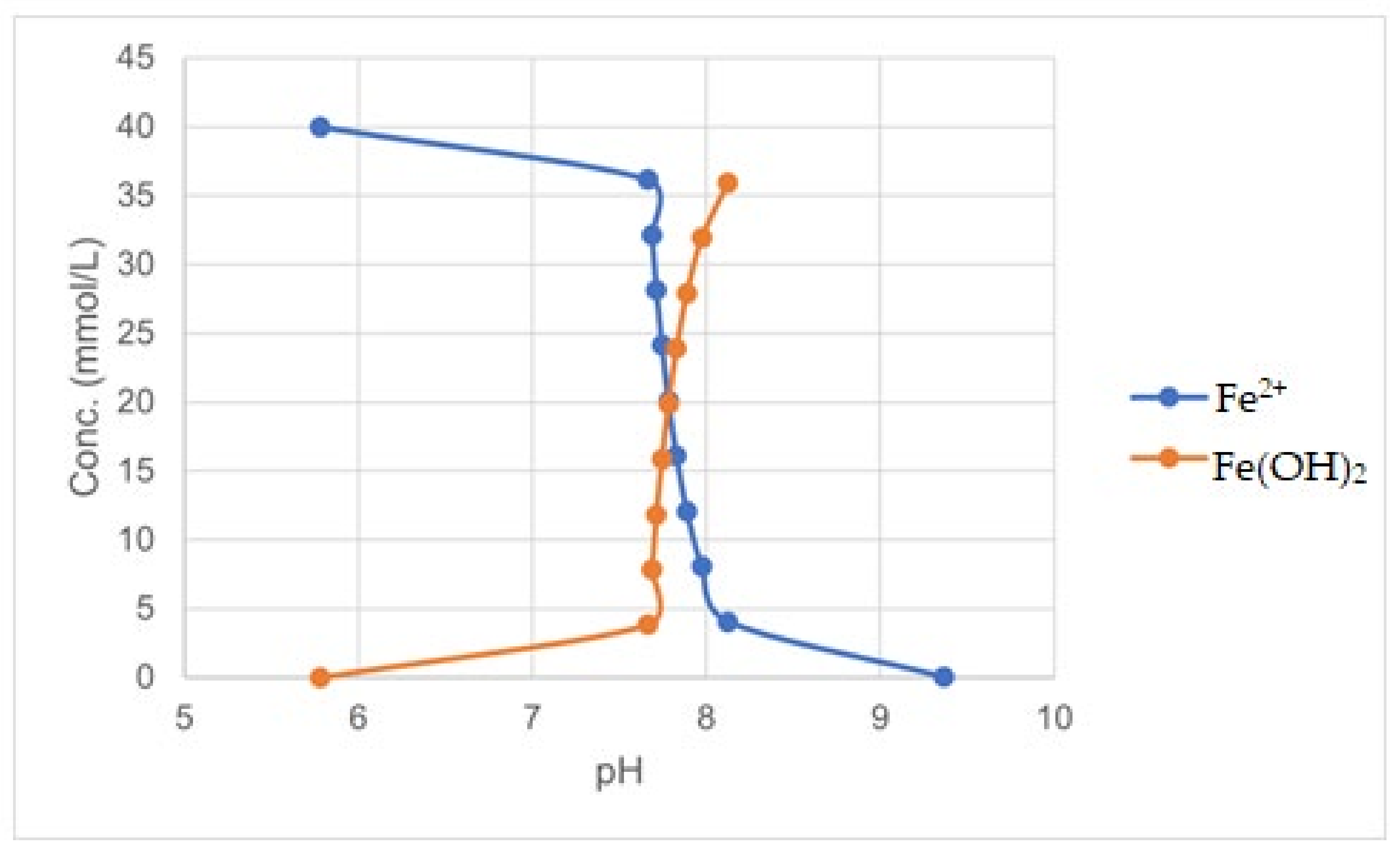
Effect of pH on Fe(OH)2 precipitation (OLI simulation).
Minerals 14 01256 g002
Figure 3. 
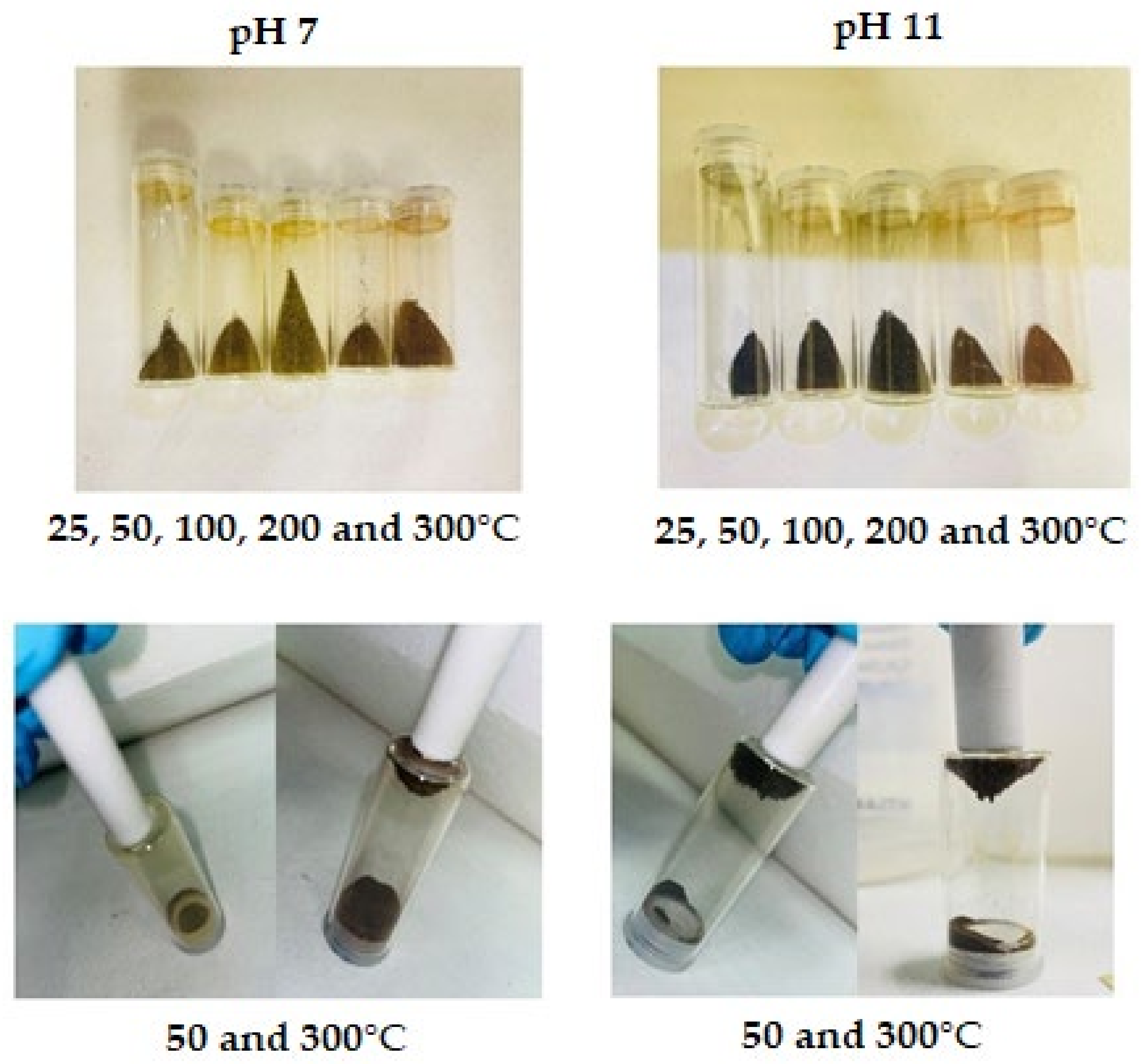
Magnetite produced with NaOH as alkali.
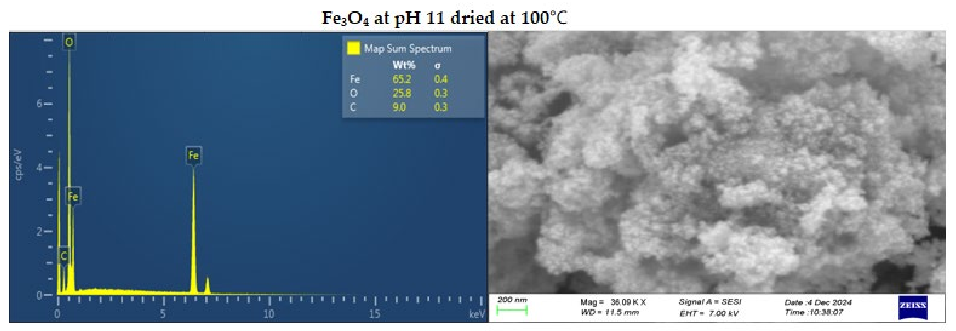
Minerals 14 01256 g003
Figure 4. 
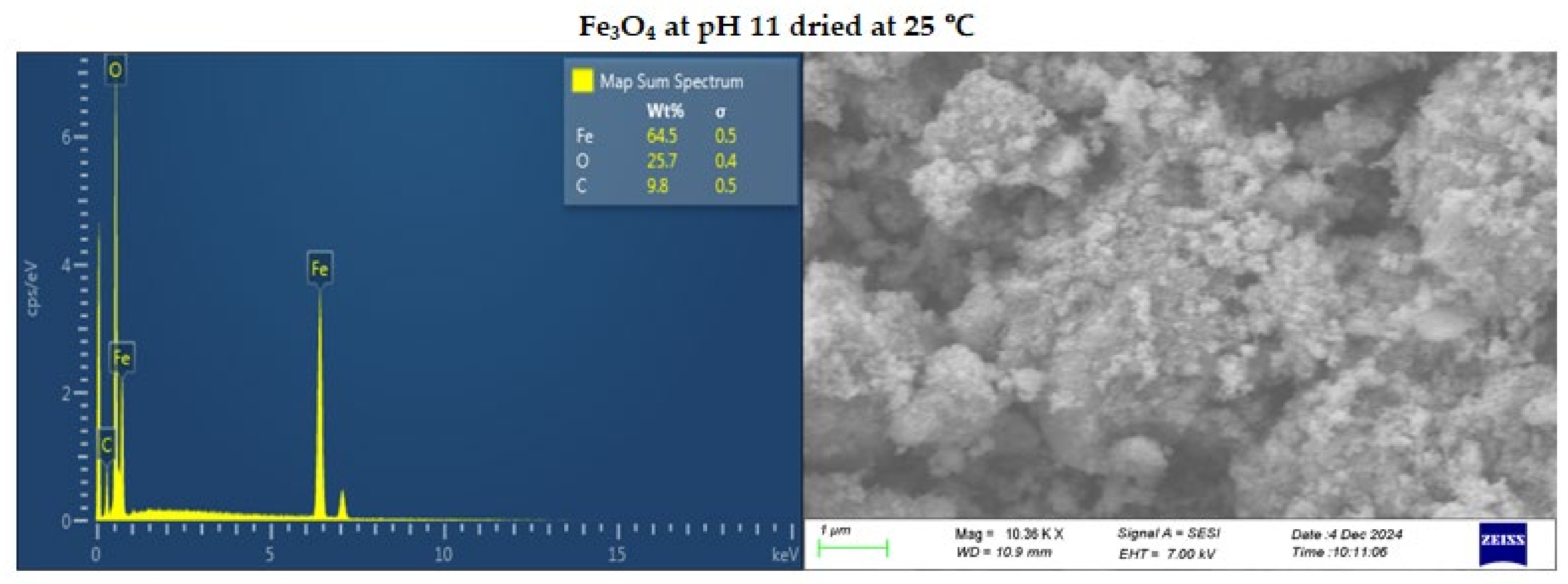
SEM-EDS image of Fe3O4 at pH 11 dried at 25 (top) and 100℃ (bottom).
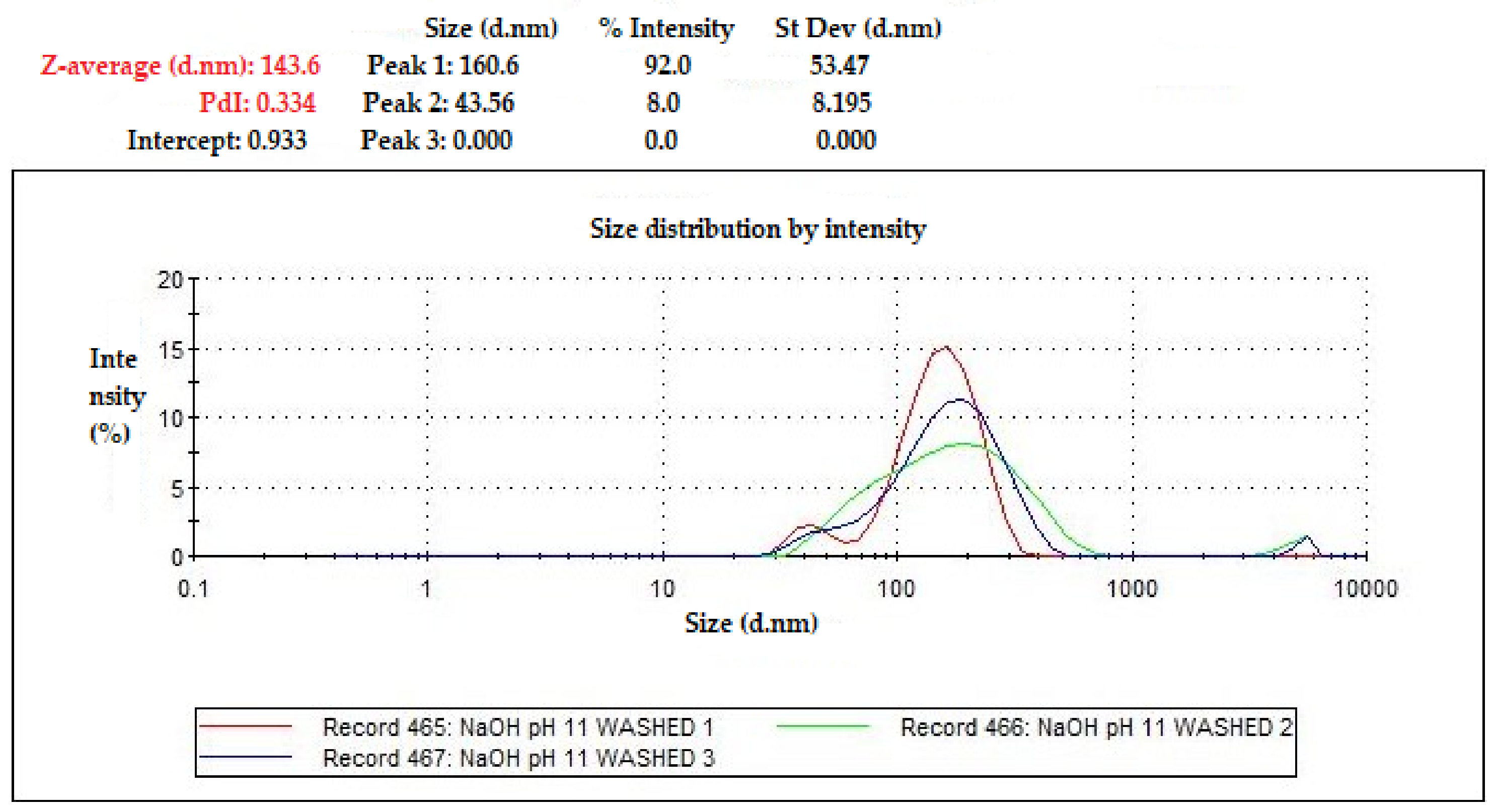
Minerals 14 01256 g004aMinerals 14 01256 g004b
Figure 5. Particle size of Fe3O4 (pH 11) measured using Zetasizer.
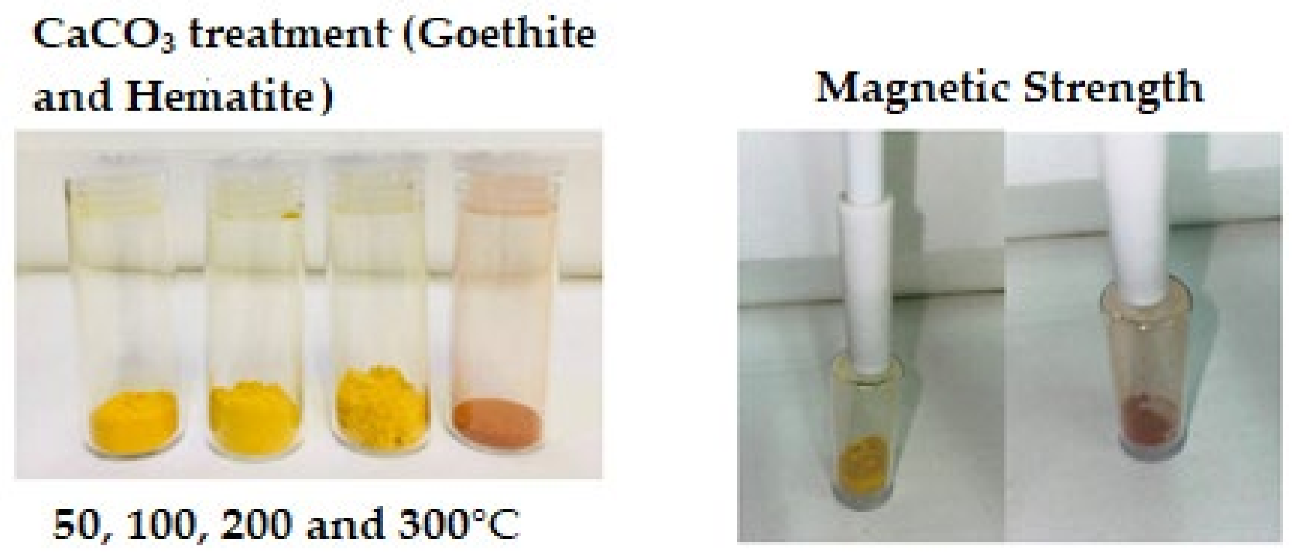
Minerals 14 01256 g005
Figure 6. Goethite formation from Fe(OH)3 when only CaCO3 was used for treatment.
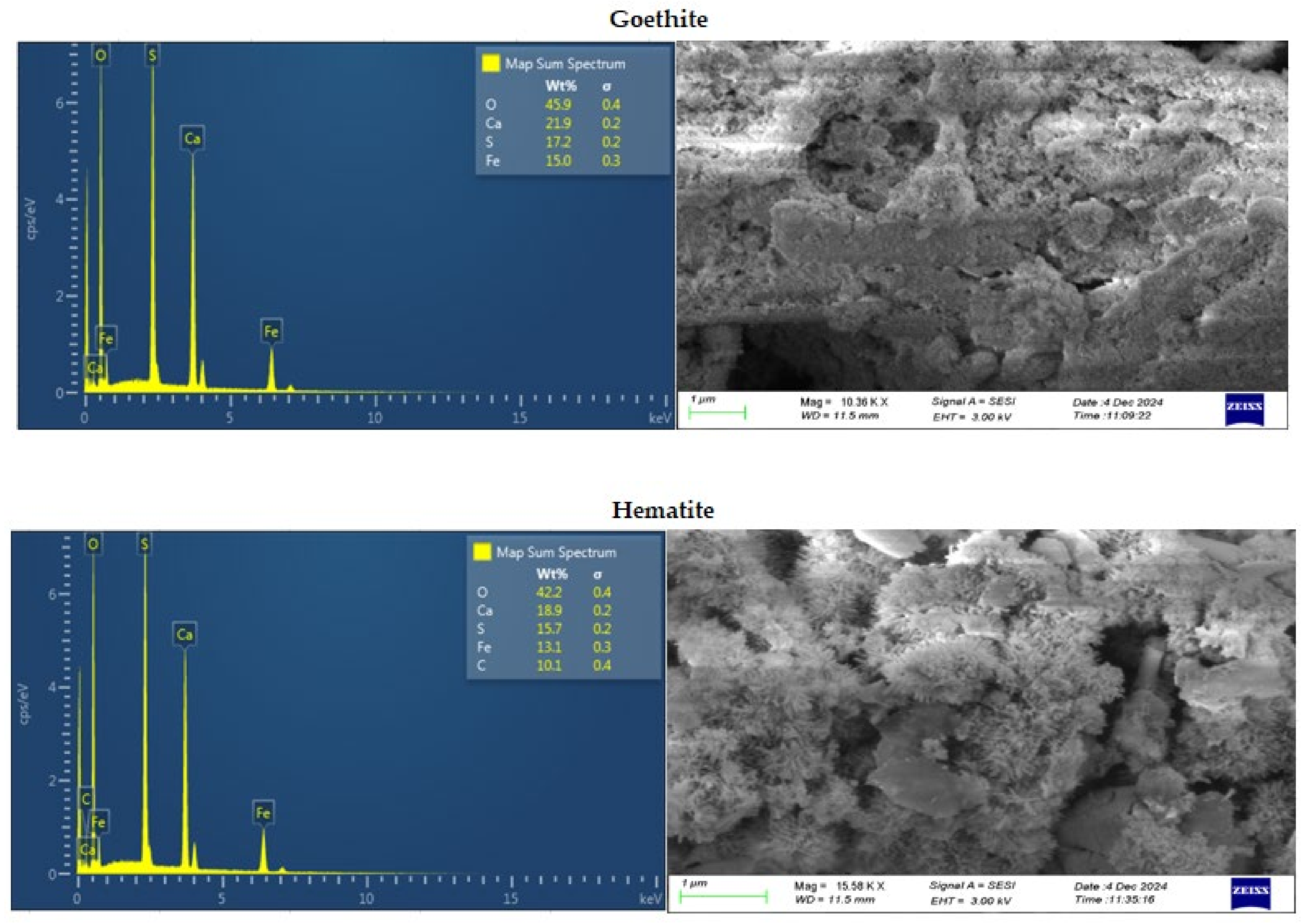
Minerals 14 01256 g006
Figure 7. SEM/EDS images of goethite (top) and hematite (bottom).
Minerals 14 01256 g007
Figure 8. XRD spectra of goethite.
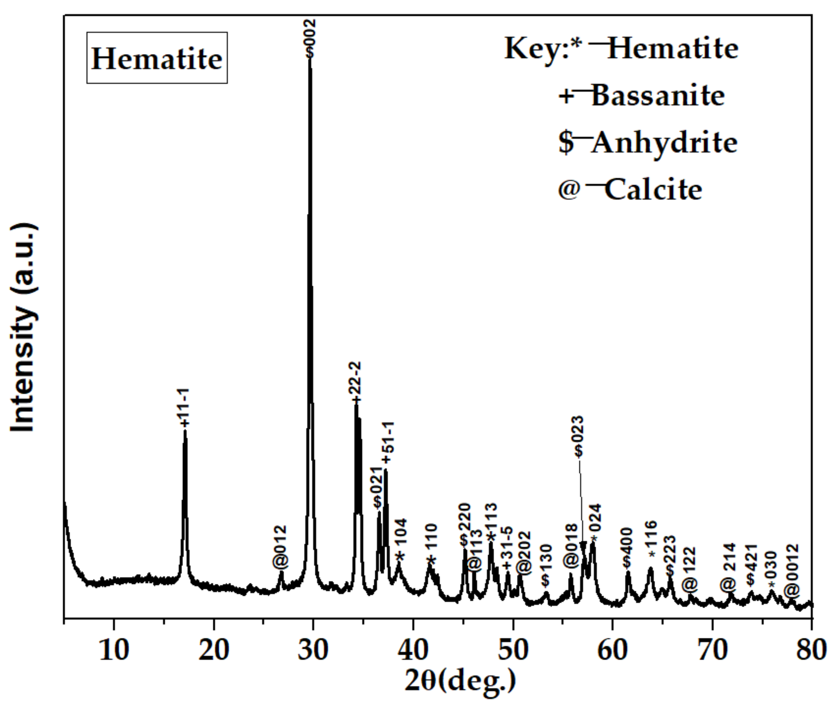
Minerals 14 01256 g008
Figure 9. XRD spectra of hematite.
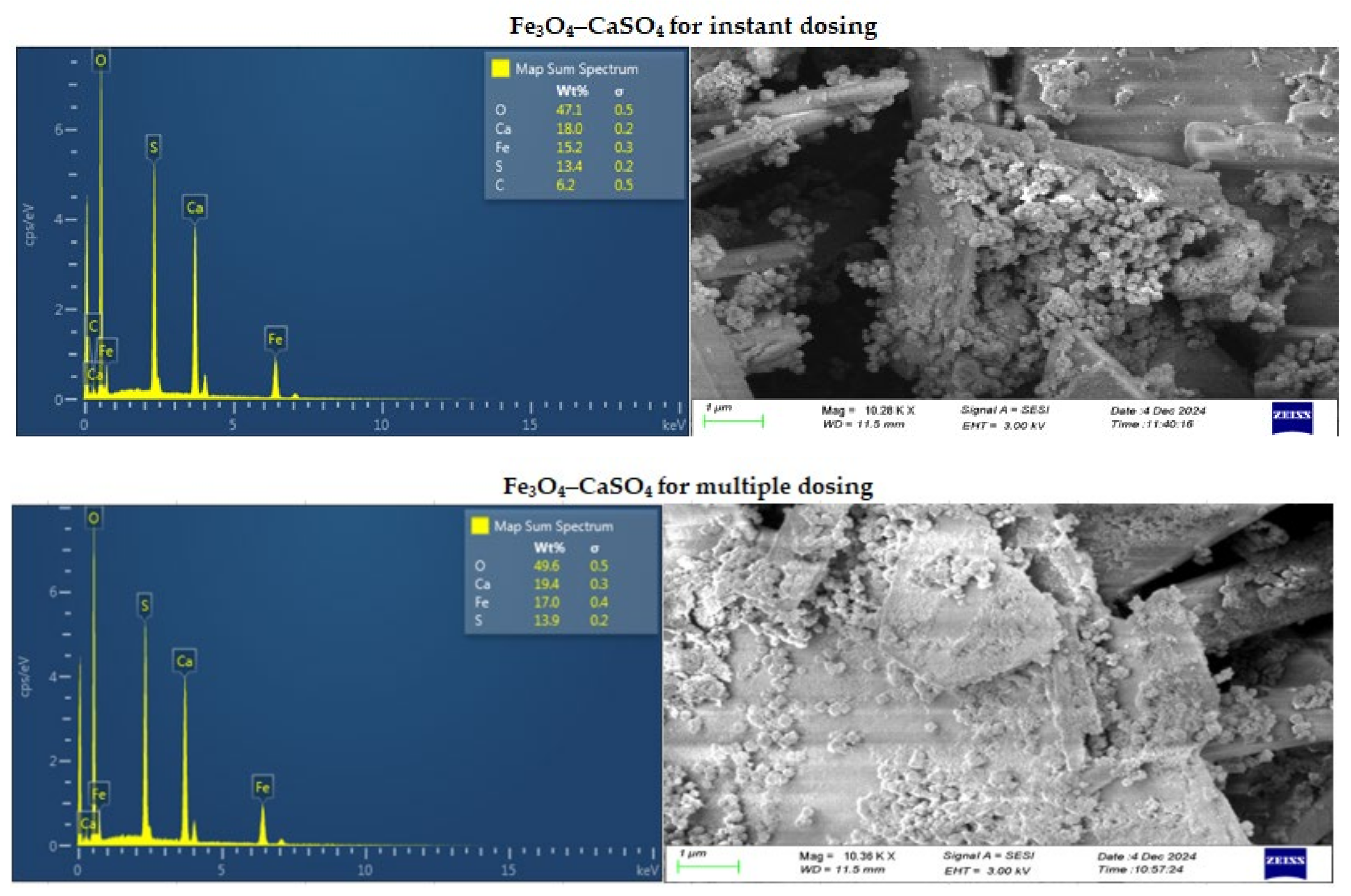
Minerals 14 01256 g009
Figure 10. SEM/EDS images of Fe3O4–CaSO4 for instant (top) and multiple (bottom) dosing.
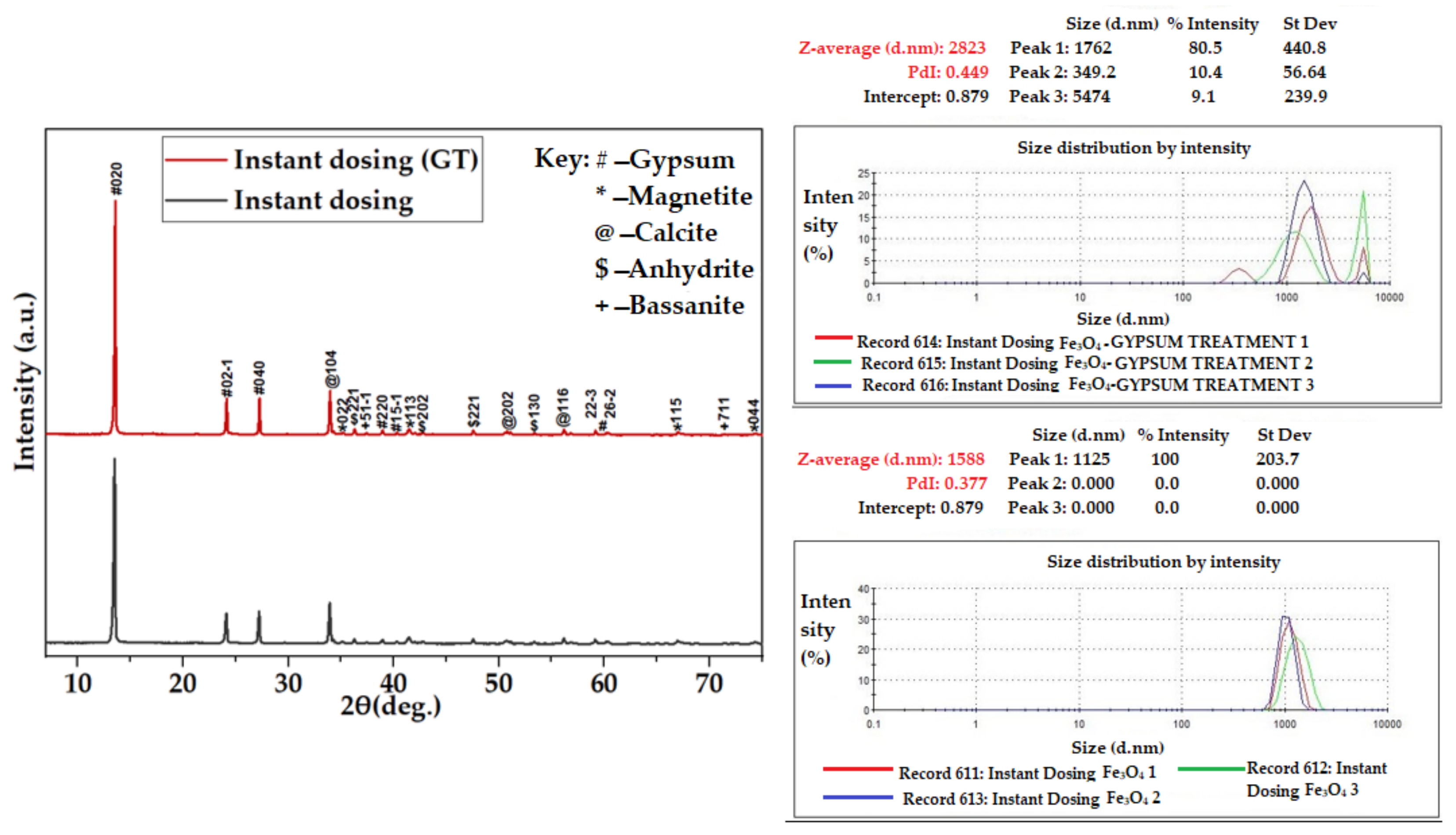
Minerals 14 01256 g010
Figure 11. XRD spectra for Fe3O4-CaSO4 in instant dosing.
Minerals 14 01256 g011
Figure 12. XRD spectra for Fe3O4–CaSO4 in multiple dosing.
Minerals 14 01256 g012
Figure 13. Particle size of Fe3O4–CaSO4 (instant and multiple dosing) measured using Zetasizer.
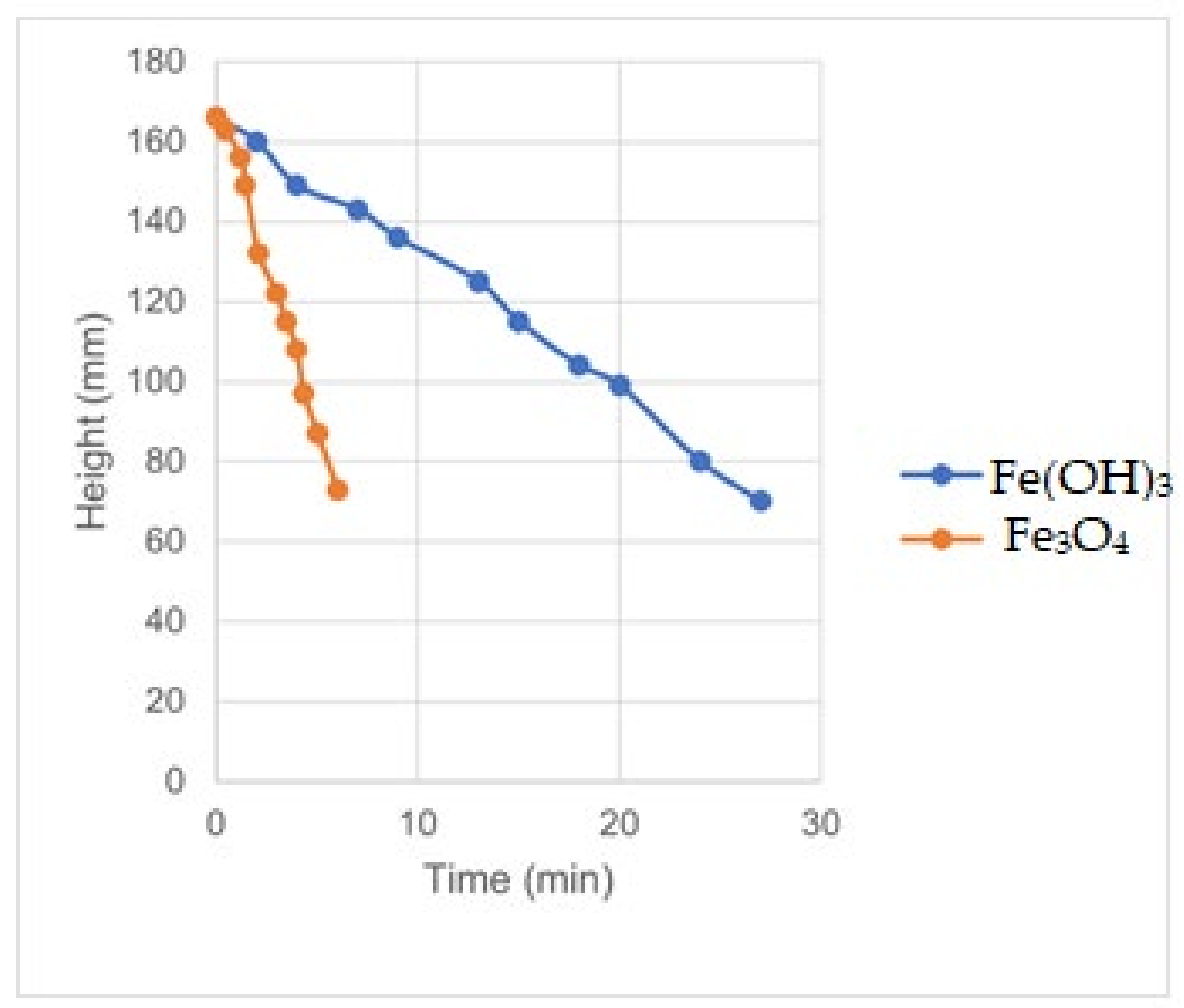
Minerals 14 01256 g013aMinerals 14 01256 g013b
Figure 14. Settling of Fe(OH)3 and Fe3O4-rich sludge.
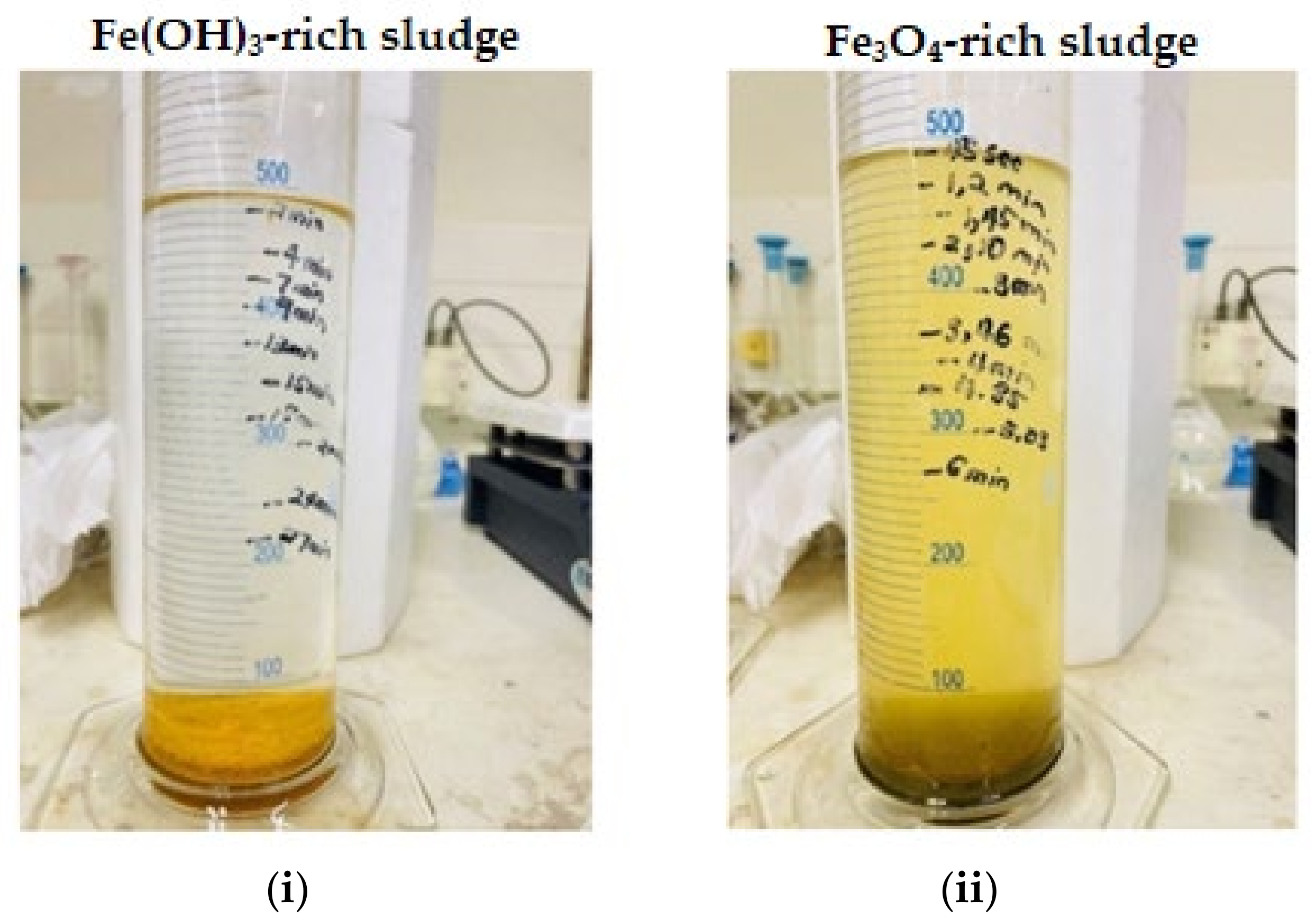
Minerals 14 01256 g014
Figure 15. Sludge settling for (i) Fe(OH)3-rich sludge and (ii) Fe3O4-rich sludge.
Minerals 14 01256 g015
Table 1. Acid required to keep Fe2(SO4)3 in solution (OLI simulation).
Fe2(SO4)3 [mmol]H2SO4 [mmol]pHFe(OH)3 (Bernalite)—Sol [mmol]Fe3+ Liq1 [mmol]SO42− Liq1 [mmol]
40.000.001.7922.7257.28120.00
40.004.001.7920.4759.53124.00
40.008.001.7918.2061.80128.00
40.0012.001.7915.9364.07132.00
40.0016.001.7913.6566.35136.00
40.0020.001.7911.3668.64140.00
40.0024.001.799.0770.93144.00
40.0028.001.796.7673.24148.00
40.0032.001.794.4575.55152.00
40.0036.001.792.1377.87156.00
40.0040.001.790.0080.00160.00
Table 2. Fe3O4 with Na2CO3.
Reactants Solid Products Solution
Na2CO3 [mmol]FeSO4 [mmol]Fe2(SO4)3 [mmol]H2SO4 [mmol]O2 [mmol]pHFe3O4 (Magnetite)—Sol [mmol]Fe(OH)3 (Bernalite)—Sol [mmol]CaSO4·2H2O (Gypsum) [mmol]CaCO3 (Calcite)—Sol [mmol]CO2—Vap [mmol]Fe3+ Liq1 [mmol]Fe2+ Liq1 [mmol]Ca2+ Liq1 [mmol]Na+ Liq1 [mmol]S6+ Liq1 [mmol]C4+ Liq1 [mmol]H2O [mmol]
040404001.830.000.000.00.00.0080.0040.000.0002000.0055,483
2040404001.850.0011.990.00.00.0068.0140.000.004020020.0055,468
4040404001.870.0023.790.00.00.0056.2140.000.008020040.0055,454
6040404001.900.0035.360.00.013.6344.6440.000.0012020046.3755,441
8040404001.940.0046.660.00.034.1433.3440.000.0016020045.8655,428
10040404001.990.0057.560.00.054.6622.4440.000.0020020045.3455,417
12040404002.080.0067.780.00.075.1812.2240.000.0024020044.8255,409
14040404002.250.0076.420.00.095.723.5840.000.0028020044.2855,407
16040404004.210.0080.000.00.0115.980.0040.000.0032020044.0255,424
18040404004.6219.6040.800.00.0142.540.0020.400.0036020037.4655,482
20040404005.1638.343.330.00.0166.790.001.660.0040020033.2155,536
Table 3. Fe3O4 with CaCO3.
Reactants Solid Products Solution
CaCO3 [mmol]FeSO4 [mmol]Fe2(SO4)3 [mmol]H2SO4 [mmol]O2 [mmol]pHFe3O4 (Magnetite)—Sol [mmol]Fe(OH)3 (Bernalite)—Sol [mmol]CaSO4·2H2O (Gypsum) [mmol]CaCO3 (Calcite)—Sol [mmol]CO2—Vap [mmol]Fe3+ Liq1 [mmol]Fe2+ Liq1 [mmol]Ca2+ Liq1 [mmol]Na+ Liq1 [mmol]S6+ Liq1 [mmol]C4+ Liq1 [mmol]H2O [mmol]
040404001.830.000.000.00.00.0080.0040.00.000.0200.00.0055,483
2040404001.850.0011.114.00.00.0068.8940.016.030.0196.020.0055,463
4040404001.860.0022.7124.60.00.0057.2940.015.380.0175.440.0055,408
6040404001.870.0034.0645.20.012.4845.9440.014.770.0154.847.5255,353
8040404001.890.0045.1565.80.032.5734.8540.014.190.0134.247.4355,300
10040404001.920.0055.9086.40.052.6624.1040.013.600.0113.647.3455,247
12040404001.960.0066.14107.00.072.7513.8640.013.020.093.047.2555,197
14040404002.080.0075.33127.60.092.844.6740.012.420.072.447.1655,152
16040404004.100.0080.00148.20.0112.700.0040.011.790.051.847.3255,128
18040404004.5119.7340.53167.60.0139.600.0020.312.420.032.440.3755,147
20040404005.0838.922.16184.60.0170.000.001.115.360.015.434.8555,169
Table 4. Fe(OH)3 with CaCO3 and O2.
Reactants Solid Products Solution
CaCO3 [mmol]FeSO4 [mmol]Fe2(SO4)3 [mmol]H2SO4 [mmol]O2 [mmol]pHFe3O4 (Magnetite)—Sol [mmol]Fe(OH)3 (Bernalite)—Sol [mmol]CaSO4·2H2O (Gypsum) [mmol]CaCO3 (Calcite)—Sol [mmol]CO2—Vap [mmol]Fe3+ Liq1 [mmol]Fe2+ Liq1 [mmol]Ca2+ Liq1 [mmol]Na+ Liq1 [mmol]S6+ Liq1 [mmol]C4+ Liq1 [mmol]H2O [mmol]
0404040101.790.0016.130.00.00.00103.870.00.000.0200.000.0055,452
20404040101.810.0027.072.10.00.0092.930.017.910.0197.9120.0055,437
40404040101.810.0038.8822.70.07.4481.120.017.260.0177.2632.5655,380
60404040101.810.0050.5643.30.027.5269.440.016.680.0156.6832.4855,324
80404040101.820.0062.0563.90.047.6057.950.016.100.0136.1032.4055,269
100404040101.820.0073.3384.50.067.6846.670.015.550.0115.5532.3255,214
120404040101.830.0084.35105.00.087.7535.650.015.040.095.0432.2555,160
140404040101.840.0095.05125.40.0107.8124.950.014.600.074.6032.1955,108
160404040101.870.00105.30145.70.0127.8714.700.014.290.054.2932.1355,058
180404040101.950.00114.69165.80.0147.915.310.014.240.034.2432.0955,013
200404040103.990.00120.00185.00.0167.640.000.015.020.015.0232.3654,993
Table 5. Effect of Fe2+ to Fe3+ mole ratio on Fe3O4 formation.
NaOH [mmol]FeSO4 [mmol]Fe2(SO4)3 [mmol]H2SO4 [mmol]O2 [mmol]pHFe3O4 (Magnetite)—Sol [mmol]Fe(OH)3 (Bernalite)—Sol [mmol]FeSO4 [mmol]Fe3+ Liq1 [mmol]Fe2+ Liq1 [mmol]S6+ Liq1 [mmol]Na+ Liq1 [mmol]H2O [mmol]
4000400.0040012.670.0080.000016040055,588
4004400.0540012.624.0072.000016440055,604
4008400.1040012.578.0064.000016840055,620
40012400.1540012.5112.0056.000017240055,636
40016400.2040012.4416.0048.000017640055,652
40020400.2540012.3620.0040.000018040055,668
40024400.3040012.2624.0032.000018440055,684
40028400.3540012.1328.0024.000018840055,700
40032400.4040011.9632.0016.000019240055,716
40036400.4540011.6536.008.000019640055,732
40040400.504007.3240.000.000020040055,748
Table 6. Composition of reactants to form magnetite.
Parameter Mol MassFeFinal SolStock SolUnit
g/molmg/L Femmol/Lmmol/Lg/LmL/LVolume/Mass
Total VolumemL 1000mL
Fe2(SO4)3·5.4H2Ommol496.9022344020099.38 200.0mL
H2SO4mmol98.00 4020019.6010.87200.0mL
H2O 400.0mL
FeSO4·7H2Ommol277.8644684020055.57 200.0mL
CaOmmol56.00 200500 11.20g CaO
CaCO3mmol100.00 200500 20.00g CaCO3
Na2CO3mmol106.00 200 21.20g Na2CO3
Table 7. Magnetite formation in the absence of gypsum.
ReactantsFeedTreated
Conditions
ReagentsConc.mol MassConc.
mmol/Lgg/L
Fe2(SO4)3·5.4H2O34.78496.9017.28
H2SO434.7898.003.41
FeSO4·7H2O34.78277.859.66
NaOH for Fe3+ and Fe2+304.3540.0012.17
NaOH dosage (g/L) 0.0012.1712.1812.2112.2412.28
Results
pH 1.807.008.209.0810.1211.08
Fe2+ (mg/L) 2290502.7167.6111.7111.755.9
Fe3+ (mg/L) 45800.000.000.000.000.00
Acidity (mg/L CaCO3) 19,8009002000.000.000.00
Temperature Magnetic strength after heating (0—none; 10—strong)
25 °C dry 0.0010.0010.0010.0010.00
50 °C dry 0.0010.0010.0010.0010.00
100 °C dry 10.0010.0010.0010.0010.00
200 °C dry 10.0010.0010.0010.0010.00
300 °C dry 10.0010.0010.0010.0010.00
Temperature Colour
25 °C dry BrownBlackBlackBlackBlack
50 °C dry BrownBlackBlackBlackBlack
100 °C dry BrownBrownDark brownBlackBlack
200 °C dry BrownBrownBrownBrownDark brown
300 °C dry BrownBrownBrownBrownBrown
Table 8. Effect of pH on the formation of goethite and magnetite.
CompoundFormulapH
811
GypsumCaSO4·2H2O1.91.5
MagnetiteFe3O48.421.2
HematiteFe2O30.00.0
ThenarditeNa2SO453.057.3
GoethiteHFeO236.720.0
Total 100.0100.0
Colour BlackBlack
Table 9. Fe(OH)3 and gypsum formation with CaCO3.
ParameterFeedTreated
Water Quality
Time (h)0.00.31345
CaCO3 (g/L) 20.00
pH1.36.16.25.45.96.1
Fe2+245724572457256924572457
Fe3+458000000
Acidity19,800.0
Sludge colour BrownBrownBrownBrownBrown
Table 10. Effect of temperature on the formation of goethite and hematite (XRD Wt%).
CompoundFormulaTemperature (°C)
100300
GypsumCaSO4·2H2O2.40.3
MagnetiteFe3O40.00.5
CalciteCaCO3 12.1
BassaniteHCaSO4.586.343.4
AnhydriteCaSO4 37.6
HematiteFe2O3 6.1
ThenarditeNa2SO40.0
GoethiteHFeO211.3
Total 100.0100.0
Colour YellowRed
Table 11. Magnetite and gypsum formation with CaCO3 and CaO.
ParameterUnitInstant DosingMultiple Dosing
FeedCaCO3 and CaOFeedCaCO3CaO
Dosing 012345012345678
Timemin 03060120150 0306090120150180181
CaCO3g 16.0 4.04.04.04.0
CaOg 3.36 1.121.121.12
pH 1.781.785.016.376.617.131.781.782.472.505.656.016.546.927.20
Fe2+mg/L24022402229011736142792402240223462346234620661396559223
Fe3+mg/L4580458000004580340761416700000
Aciditymg/L19,800400036003100270080019,80019,40012,0009600290025001300800600
Temperature°CMagnetic strength after heating (0—none; 10—strong) pH 7.1Magnetic strength after heating (0—none; 10—strong) pH 7.2
50 6.006.00
100 8.008.00
200 8.008.00
300 8.008.00
Temperature°CColourColour
50 BrownBrown
100 Black-greyBlack-grey
200 GreyGrey
300 BrownBrown
Table 12. Magnetite combined with gypsum.
CompoundFormulaComposition (%)
InstantMultiple
GypsumCaSO4·2H2O92.291.0
MagnetiteFe3O46.76.5
CalciteCaCO30.81.3
BassaniteHCaSO4.50.01.0
AnhydriteCaSO40.30.1
HematiteFe2O30.00.1
ThenarditeNa2SO40.00.0
GoethiteHFeO20.00.0
Table 13. Single and multiple dosing for sludge production.
ParameterUnitInstant DosingMultiple Dosing
FeedCaCO3 and CaOFeedCaCO3CaO
Dosing 012345012345678
Timemin 03060120150 0306090120150180181
CaCO3g 16.0 4.04.04.04.0
CaOg 3.36 1.121.121.12
pH 1.781.785.016.376.617.131.781.782.472.505.656.016.546.927.20
Fe2+mg/L24022402229011736142792402240223462346234620661396559223
Fe3+mg/L4580458000004580340761416700000
Aciditymg/L19,800400036003100270080019,80019,40012,0009600290025001300800600
Table 14. Separation of gypsum and Fe3O4.
ParameterInstantMultiple
Time (h)2424
FeedFe3O4 GypsumFe3O4 Gypsum
Total mass in 100 sat gypsum solution (Mg)500.00500.00
CaSO4·2H2On (Mg)370.00370.00
Fe3O4 (mg)130.00130.00
Dry product mass (mg) (100 °C)84.90149.50
Magnetite (XRD results) (%)6.5011.70
MagneticYesyes
Table 15. XRD results (Wt %).
CompoundFormulaDosing
Instant (%)Multiple (%)
GypsumCaSO4·2H2O91.082.1
MagnetiteFe3O46.511.7
CalciteCaCO31.35.8
BassaniteHCaSO4.51.00.0
AnhydriteCaSO40.10.1
HematiteFe2O30.10.3
Table 16. Production of Fe3O4 sludge.
Parametermmol/LgLMass (g)Vol (mL)Stockg/LStock Volume
H2O 400
H2SO44.098.01.00.390.225.01.96200
Fe2(SO4)3·5.4H2O4.0496.91.01.99 5.09.94200
FeSO4·7H2O4.0277.91.01.11 5.05.56200
CaO for Fe2+5.056.01.00.28 0.28
Total Volume (mL) 1000
Products
Fe3O44.0231.61.000.93 5.0 200
Gypsum21.0172.01.003.61 5.0
Total 403.61.004.54
Table 17. Production of Fe(OH)3-rich sludge.
Parametermmol/LgLMassVolStockg/LStock Volume
gmL
H2O 400
H2SO44.098.01.00.390.225.01.96200
Fe2(SO4)3·5.4H2O4.0496.91.01.99 5.09.94200
FeSO4·7H2O0.0277.91.00.00 5.00.00200
CaO for Fe2+0.056.01.00.00 0.00
Total Volume (mL) 1000
Products
Fe3O44.0231.61.000.93
Gypsum16.0172.01.002.75
Total 403.61.003.68
Table 18. Settling rate of Fe3O4/gypsum-rich sludge.
TimeHeightRate
MinMmm/h
0.0166
0.51630.40
1.21560.50
1.51490.70
2.11320.97
3.01220.88
3.51150.88
4.01080.87
4.4970.95
5.0870.94
6.0730.93
Average 0.80
Table 19. Settling rate of Fe(OH)3/gypsum-rich sludge.
TimeHeightRate
Minmmm/h
0166
21600.18
41490.26
71430.20
91360.20
131250.19
151150.20
181040.21
20990.20
24800.22
27700.21
Average 0.21
Disclaimer/Publisher’s Note: The statements, opinions and data contained in all publications are solely those of the individual author(s) and contributor(s) and not of MDPI and/or the editor(s). MDPI and/or the editor(s) disclaim responsibility for any injury to people or property resulting from any ideas, methods, instructions or products referred to in the content.

