Article

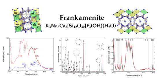
Frankamenite: Relationship between the Crystal–Chemical and Vibrational Properties

1
Vinogradov Institute of Geochemistry, Siberian Branch of the Russian Academy of Sciences, Favorsky Str. 1A, Irkutsk 664033, Russia
2
Zavaritsky Institute of Geology and Geochemistry, Ural Branch of the Russian Academy of Sciences, Ak. Vonsovsky Str. 15, Ekaterinburg 620110, Russia
3
State Key Laboratory of Geological Processes and Mineral Resources, Collaborative Innovation Center for Exploration of Strategic Mineral Resources, School of Earth Resources, China University of Geosciences, Wuhan 430074, China
4
Mikheev Institute of Metal Physics, Ural Branch of the Russian Academy of Sciences, S. Kovalevskaya Str. 18, Ekaterinburg 620990, Russia
*
Author to whom correspondence should be addressed.
Minerals 2023, 13(8), 1017; https://doi.org/10.3390/min13081017
Submission received: 15 June 2023 / Revised: 18 July 2023 / Accepted: 18 July 2023 / Published: 29 July 2023
(This article belongs to the Special Issue Vibrational Spectroscopy in Mineralogy and Archaeology)

Abstract

:
The study provides novel insights into the crystal–chemical and optical characteristics of frankamenite. Frankamenite belongs to a special group (canasite group) of the complex alkaline Ca-(K)-(Na) silicates, and it was found in charoitites from the only known location, Murun Massif, Eastern Siberia, Russia. The crystal–chemical, vibrational, and optical properties of frankamenite were investigated by combining electron probe microanalysis (EPMA), single-crystal X-ray diffraction (SCXRD), infrared (IR) absorption, Raman, UV-Visible absorption, and electron spin resonance (ESR) spectroscopy. The behavior of the peaks in the IR spectra was also studied using ab initio calculations. Detailed characteristics of the internal composition and structure of the mineral species were described, and vibrational and optical properties based on these peculiarities were interpreted. The thermally stimulated reorientation of the H2O molecules and OH groups was studied by thermo-Raman spectroscopy. Octahedral cationic positions can be readily doped with transition metal and lanthanide ions that provide a promising opportunity to adjust the Ce3+ luminescence. Hence, frankamenite is a potential material for ion exchange, novel phosphors, and luminophores.

Graphical Abstract

1. Introduction

Frankamenite, K3Na3Ca5[Si12O30]F3(OH)(H2O), is a complex alkaline silicate and unique mineral found today in only one deposit in the world (Murun Massif, Russia). According to the silicate minerals hierarchy of Day and Hawthorne [1], frankamenite is a tube silicate with a one-dimensional tetrahedral polymerization. The [Si12O30]12− -tubes in frankamenite extend along the c-axis and consist of two linked ribbons of six-membered rings. This tube is topologically identical to the 3V12 in the charoite structure (see [2] and therein). The silicon–oxygen radical has the designation 3T12, where T means “tetrahedron”, 3 is the connectivity of the tetrahedron, and 12 is the number of such tetrahedra in the geometrical repeat unit [1]. The tubes are connected to corrugated sheets of Ca2+ and Na+- octahedra parallel to the c-axis. The internal channels are occupied by K+ ions and additional H2O groups. The silicate tubes and sheets of (CaO4(OH)F)8−- and (NaO4F2)9−-octahedra occur in layers, alternating along the c-axis.
The same type of tube (3T12) can be found in the crystal structures of canasite [3] and fluorcanasite [4], insofar as frankamenite is the triclinic polymorph of the above minerals. Canasite contains four (OH) sites, while in fluorcanasite there are two F sites, an (OH) site, and a mixed (F,OH) site, all of which are bound to the Na+ and Ca2+-octahedra.
The minerals of the canasite group are listed for comparison in Table 1. The crystal structure of canasite, discovered in the Khibiny Massif in the 1950s, has been determined over several decades [5,6] and was successfully refined by Rozhdestvenskaya et al. in 1988 [3]. They also noted differences in the chemical compositions of the canasite minerals from the Khibiny and Murun Massifs [3], the latter of which was also characterized by Evdokimov and Regir in 1994 [7]. In 1992, Nikishova et al. presented the results of crystal structure refinement of the mineral from Yakutian charoitites (Murun Massif), calling it triclinic canasite [8]. The structure of this variety was refined within the space group P1, which explained the difficulties [3] encountered while working with these samples and the presence of additional reflections in the diffraction patterns. The crystal structure and interatomic distances slightly differ from those of monoclinic canasite from the Khibiny Massif. In 1994, triclinic canasite was approved by the CNMNC as a new mineral called frankamenite [9]. It was named after the Russian mineralogist and crystallographer, professor of St. Petersburg State University, V.A. Frank-Kamenetsky. An interesting fact is that charoite was also initially mistaken for lilac canasite, but after a detailed study, it became recognized as another mineral species [10]. The last paper on the refinement of its structural features was published in 1996 [11]. In 2003, Rastsvetaeva et al. [12] reported on canasite from the Khibiny Massif containing a high content of fluorine. This species differs from canasite in symmetry (space group Cm vs. C2/m of canasite) and occupancies of the octahedral positions. These characteristics enabled its approval in 2007 by the CNMNC as a new mineral called fluorcanasite [4]. According to [12], fluorcanasite can be considered either as a fluorine analogue of canasite or as a monoclinic analogue of frankamenite. The intensity of studies of minerals of the canasite group has noticeably declined over the past 15 years, despite the fact that, for example, the optical and vibrational properties of frankamenite are yet to be studied.
Deciphering and interpreting the vibrational modes of frankamenite remain questionable. However, having structural data (P1 (No. 1), point group C1 (1)), it is possible to calculate a set of phonon modes in the center of the Brillouin zone based on factor–group analysis [13]: Γ = 183A (using https://www.cryst.ehu.es/rep/sam.html (accessed on 15 June 2023)). The latter indicates the polarity of the frankamenite crystal.
Within the last few decades, canasite-based materials have received unprecedented interest. These compounds are potential glass–ceramic materials. Glass–ceramics are polycrystalline solids obtained by the controlled crystallization of glass during a heat treatment process that contain one or several crystalline phases, and in most cases, a residual glassy phase. Bioactive silicate glass–ceramics can be used as long-term implants due to their relatively high mechanical strength and only negligible and slow solubility of silicates in human body fluids [14]. Studies concerning the development of glass–ceramics, which are potentially suitable for biomedical applications, have reported that CaO, P2O5, and F, regardless of their origin, must be the essential compositional components of glass–ceramic systems ([15] and therein). One of the potential glass–ceramic materials is canasite [16]. The stoichiometric canasite forms a stable glass, requiring only a few percent excess fluoride to achieve efficient nucleation, and it is easy to produce essentially monophase glass–ceramics [17].
According to [18], an ideal osteoconductive bioglass–ceramic should be free of Al2O3. Fluorcanasite (with composition K2Na4Ca5Si12O30F4) glass–ceramics were obtained by controlling the glass crystallization in the SiO2–K2O–Na2O–CaO–CaF2 system [19]. Bandyopadhyay-Ghosh et al. (2010) [20] reported modified fluorcanasite glass–ceramic compositions based on changing the Na2O and CaO molar ratios and adding P2O5.
Due to good castability combined with excellent cell response in vitro, modified fluorcanasites have great potential for use as load-bearing, osteoconductive biomaterials in orthopedics, implantology, and reconstructive facial surgery [18,20,21], whereas stoichiometric fluorcanasite glass–ceramics showed poor mechanical properties and crumbled during mechanical processing [22]. By modifying the compositions, the biological activity of the modified glass–ceramics can be significantly increased [23,24]. The addition of lithium disilicate increases the chemical resistance of fluorcanasite-based glass–ceramics [25,26]. Vyas et al. (2022) [27] found out that with increased fluorcanasite content in the composition, hydrophilicity also increases over the entire surface of the sample, and, subsequently, cell adhesion and proliferation is raised.
Fluorcanasite glass–ceramics have excellent mechanical properties [28]. The type, size, and volume ratio of the primary crystalline phases in the material directly affect the properties of canasite-based glass–ceramics [29]. Phase evolution in canasite-based compositions is complex, and small compositional modifications significantly change the crystallizing product and the nucleation mechanism [30]. The main crystalline phases are canasite and frankamenite, often having an interpenetrating lattice structure [31]. At relatively low temperatures, frankamenite predominantly nucleates homogeneously throughout the glass [30]. According to published data [30,31], the nucleation temperature for the phases of the canasite group is ~520 °C, and the temperature of crystal growth is ~780 °C.
Glass–ceramics find applications in cookware, hermetic sealing, and electronic substrates, among others. One of the applications of glass–ceramics is for sealing solid oxide fuel cell (SOFC) components, mainly using alkaline earth-metal-based aluminosilicate glass–ceramics [32].
It is important to understand that in order to create such relevant modern materials, the widest possible knowledge of the compounds used is necessary. Recently, Kaneva et al. (2021) [33] made the first attempt to study the vibrational properties of this mineral. However, the data are only descriptive. This work reveals new insights into the crystal–chemical and optical properties of frankamenite.

2. Materials and Methods

2.1. Sample Description

The studied frankamenite sample was taken from the Murun Massif (Malyy Murun), Aldan Shield, Siberia, Russia. Frankamenite is associated with charoite, pectolite, microcline, aegirine, tinaksite, and quartz [7]. The mineral forms flattened, rosette-shaped or radial–radiant aggregates and can have different colors: from gray, bluish, and lilac-gray to greenish and brown (Figure 1).
Moreover, frankamenite is an unusual collectible stone, and its presence in a sample along with charoite, which is a well-known and visually very attractive gem material, as well as various associated minerals, creates an interesting appearance [34].

2.2. Crystal–Chemical Analysis

Mineral compositions were analyzed with a JEOL JXA-8230 Electron Probe Microanalyzer (Jeol, Tokyo, Japan) equipped with five wavelength-dispersive spectrometers (WDS) (Jeol, Tokyo, Japan ). The samples were firstly coated with a thin conductive carbon film prior to analysis. The precautions suggested by [35] were used to minimize the difference of carbon film thickness between samples and obtain an approx. 20 nm uniform coating. Operating conditions for quantitative WDS analyses involved an accelerating voltage of 15 kV, a beam current of 5 nA, and a 20 µm spot size. Data were corrected online using a ZAF (atomic number, absorption, fluorescence) correction procedure. The content of H2O was calculated by difference and then involved into the ZAF correction procedure. The peak counting time was 10 s for Ca, Mg, K, F, Si, Al, Fe, Na, Sr, and Ba and 20 s for Ti and Mn. The background counting time was 1/2 of the peak counting time on the high- and low-energy background positions. The following standards were used: diopside (Ca, Mg), sanidine (K), fluorite (F), olivine (Si), jadeite (Na), rhodonite (Mn), SrF2(Sr), pyrope garnet (Al, Fe), and barite (Ba). Electron probe microanalysis (EPMA) results (determined over 8 spots) obtained for the studied frankamenite sample are reported in Table 2. The atom proportions in atoms per formula units (apfu) were derived on the basis of 12 Si + Al cations.
The crystal structure of the frankamenite sample was studied using a Bruker AXS D8 VENTURE automated diffractometer equipped with a four-circle Kappa goniometer, a CCD detector, and monochromatized MoKa radiation. The operating conditions were 50 kV and 1 mA. The detector-to-crystal working distance was 40 mm. The collection strategy was optimized with the APEX2 (Bruker AXS Inc, Berlin, Germany) suite package [36]. A combination of several ω and ϕ rotation sets was used for the recording of the entire Ewald sphere (±h, ±k, ±l) up to θmax ~33°. The extraction of the reflection intensities and the correction of the Lorenz polarization effect was carried out with the SAINT package [37]. The SADABS software was provided for a semi-empirical absorption correction [38], and the XPREP [39] was used for the calculation of the intensity statistics. The crystal structure was refined in the space group P1 using the CRYSTALS program [40]. The twin operation has been identified with the ROTAX program [41] with the following matrix [101, −1−1−0.5, 00–1]. The refined parameters were scale factor, atom positions, anisotropic/isotropic displacement parameters, and extra-Si-framework cations’ occupancies. Occupancies for Si and O atoms were constrained to 1. In [8], the designation “M” was used to denote octahedral positions with mixed occupancies of Ca and Na, numbered from 1 to 8. This nomenclature was employed in our study. For the refinement of the Ca and Na occupancies in the M-octahedra the restrain Ca + Na = 1 ± 0.01 was imposed. The results of X-ray diffraction study of the frankamenite sample could not be used to locate H atoms of OH groups and water molecules. The quality of the crystals was not good; after several attempts at data collection, the reported one was found to be the best.
Initial fractional coordinates and atom labeling were taken from [10]. The summary data regarding the single crystals, the data-collection parameters, and the structural refinements are given in Table 3, whereas final atomic coordinates, site occupancies, and equivalent displacement parameters are reported in Table S1 of Supplementary Materials. Selected interatomic distances and angles are given in Tables S2 and S3 of Supplementary Materials, respectively.
The CIF was deposited with the Cambridge Crystallographic Data Centre (CCDC 2171487).
A statistical analysis of structural data was performed using the calculation of the coordination polyhedra characteristics. In this analysis, we applied the calculations of the parameters earlier described in [42]. The geometric parameter calculation as a measure of polyhedral irregularity was based on the centroid method developed by [43]. A computer program (IVTON) which calculates these parameters is available [44]. Bond valence calculation (Table S4 of Supplementary Materials) was performed using the parameters obtained by [45] and [46]. The figures showing structural details were prepared using the program VESTA (version 4.3.3, Tsukaba, Kyoto, Japan) [47].

2.3. Ab Initio Calculations

Ab initio calculations of the frankamenite crystal structure were performed using the density functional theory (DFT) [48] that was implemented in the VASP package [49]. The projector augmented wave (PAW) with the exchange–correlation functional in Perdew–Burker–Ernzerhof (PBE) [50] in the generalized gradient approximation (GGA) was used to construct the basis wave functions. The cutoff energy threshold for these potentials was chosen to be E cutoff = 600 eV. Integration during iterative matching was performed over a uniformly distributed grid of 4 × 3 × 2 k-points throughout the Brillouin zone. The crystal structure in the GGA calculations was preliminarily relaxed to an interatomic force value ≥0.005 eV/A. The phonon spectra were calculated at the center of the Brillouin zone (Γ) in a similar GGA approximation.

2.4. Infrared Spectroscopy

Infrared spectra were measured with a Fourier-Transform Infrared (FTIR) spectrometer FT-801 (Simex, Novosibirsk, Russia). The powdered samples were mixed with anhydrous KBr, pelletized, and analyzed in the range of 480–4000 cm−1 at a resolution of 2 cm−1, and 32 were collected for each spectrum. The FTIR spectrum of an analogous pellet of pure KBr was used as a reference. The mixed and pelletized sample was heated at different temperatures to study the frankamenite dehydration. The methodology was described in [51].

2.5. Raman Spectroscopy

Raman spectra in the range of 20–4000 cm−1 were measured in the Common Use Center “Geoanalitik” using a Horiba LabRam HR800 Evolution equipped with an Olympus BX-FM confocal microscope, He-Ne laser (radiation wavelength 633 nm, laser power of 4 mW), and a Linkam TSM 600 heating/cooling stage to study in situ Raman spectra in the temperature range of −190–600 °C; no photoluminescence was observed with this excitation. An Olympus 50× objective (numerical aperture = 0.7) was used. The acquisition time was 20–30 s, with 2 accumulations per spectral segment. The diffraction grating of 1800 gr/mm and an electrically cooled charge-coupled device detector were used to record the spectra. The spectrometer calibration was guided along the Rayleigh line and the emission lines of a neon lamp. The re-equipment and comprehensive development of the “Geoanalitik” shared research facilities of the IGG UB RAS is financially supported by the grant of the Ministry of Science and Higher Education of the Russian Federation (Agreement No. 075-15-2021-680).

2.6. Optical Spectroscopy and ESR

The photoluminescence and excitation spectra were registered at room temperature using a LS-55 spectrofluorimeter (Perkin-Elmer, Valencia, CA, USA). The optical absorption spectrum was measured on the frankamenite plate with thickness of approx. 1 mm using a Lambda-950 spectrophotometer (Perkin-Elmer, CA, USA). Electron Spin Resonance spectrum was recorded using RE-1306 radiospectrometer 6 (KBST, Yartsevo, Russia) operated at a microwave frequency of 9380 MHz.

3. Results

3.1. Crystal Chemistry and Structure Description

Chemical analyses of frankamenite published earlier in the literature have been combined in [52]. The atom proportions in atoms per formula units (apfu) for studied frankamenite are reported in Table 2. The composition of our frankamenite in relation to Na2O and CaO is almost identical to that of the other Murun samples reported in [52]. There is a higher K2O content in relation to previously published analyses. The content of F in the literature ranges from 3.72 to 5.75 wt.%, while the content of F in our sample has a range of 4.30–4.61 wt.%.
Considering the results of electron probe microanalysis and crystal structure refined, the following crystal–chemical formula can be proposed for the studied frankamenite: K2.97Ba0.01Na2.74Ca5.03Mn0.08Sr0.03Fe0.01[Si11.99Al0.01O30](F3(OH))·0.64H2O.
The projection of crystal structure along the a-axis is shown in Figure 2.
When analyzing the geometric structural characteristics of the frankamenite model refined, we used several significant parameters to identify the degree of distortion. They were calculated and are listed in Table 4. Using the centroid method, where the centroid is defined as the point in the coordination polyhedron having the minimum variance of the distances to the vertices, we may obtain the parameters defining the displacement of the central atom from its ligands (rv, ΔV, rs, Δ, Table 4). The volume eccentricity (ECCv) and the volume sphericity (SPHv) describe the displacement of the central atom from its ligands and the deviation of vertices of a polyhedron from the surface of a best-fit sphere to the ligand positions, respectively. Bond length distortion (BLD) is a measure of the dispersion of the individual bond lengths, and the bond angle variance (TAV and OAV) is a measure of the dispersion of the individual angle. The quadratic elongation (TQE and OQE) is dimensionless and equal to 1 for a regular polyhedron, while for a distorted polyhedron, it is >1.
Average tetrahedra distances for Si1–Si12 lie within 1.60(2)–1.64(1) Å (Table S2 of Supplementary Materials); the measured Si–O individual distances range from 1.513(9) to 1.692(7) Å (Table S2 of Supplementary Materials). The differences between the experimental values and the calculated rv and rs values do not exceed 0.005 Å, and they lie within the estimated standard deviations range. A relatively low BLD values of parameter, not exceeding 3%, indicate that the tetrahedral bond lengths are closely grouped around an average value. The quadratic elongations (TQEs) are in the range of 1.003–1.010, which means that the tetrahedra are distorted. Indeed, the high values of the TAV parameters (10.076–45.552) confirmed this. The eccentricity (circle has eccentricity = 0, ellipses have an eccentricity of less than 1) ranges from ~0.07 to ~0.15 for Si-tetrahedra, and the sphericity (it is less than 1 for non-spherical objects) is equal to 0.9999 or 1.0000.
Information about the coordination numbers for cation and anion positions and BVS values are represented in Table S4 of Supplementary Materials. Relevant information about the cation site population and mean atomic number are given in Table 5. A satisfactory agreement between the mean electron numbers and the average interatomic distances (Table 5 and Table S2 of Supplementary Materials), as derived by X-ray and EPMA measurements, was found. The <cation–anion> distance (r, Table 4) and the volume (Vp) of the M1 and M8 octahedra are the largest and the smallest, respectively. This provided grounds to distribute ions with an ionic radius greater than those of Ca and Na (according to [57]) into the M1 position and ions with an ionic radius smaller than those of Ca and Na into the M8 position (Table 5). The calculated average distances from the volume center to the ligands and from the centroid to the ligands deviated a little from the experimental values of the average distances from the cation to the ligands: −0.000–0.003 Å. It should be noted that the crystal structure exhibiting the octahedra sites was also lightly distorted. The main differences in the M-octahedra distortion parameters involve the OAV parameter, which ranges from ~46.6 to ~73.5. The eccentricity achieves 0.061, and the sphericity is much less than 1 (to 0.94). Generally, OQE parameters of octahedra are very similar.
The distortion parameters for the K sites (Table 4) are generally higher than those of other polyhedra of the crystal structure. The K2 site exhibits the greatest volume eccentricity value, and for the volume sphericity, the more distorted is the K1 site.

3.2. Ab Initio Calculations

The calculated phonon spectrum of frankamenite considering the data on its structure presented in this paper allows us to define the full vibrational representation as Γ = 183A. According to the ab initio calculations, frankamenite was found to be characterized by vibrations with the following frequencies: four modes corresponding to vibrations of the water region and OH-radicals at ~3490–3722 cm−1 and one mode characterizing the H–O–H vibrations of water ~1585 cm–1. The other modes can be conditionally divided into three spectral groups of vibrations of the silicon–oxygen framework: 53–546 cm–1 (126 modes), 576–789 cm–1 (21 modes), and 895–1108 cm–1 (31 modes). A detailed analysis of the vibrations of the crystal according to the DFT data showed the predominant vibration of the Si–O rings and is discussed in detail below.

3.3. Infrared and Raman Spectroscopy

The absorption and Raman spectra of frankamenite are given in Figure 3 and Figure 4.
In view of the polarity of the crystal (all the presented vibrations are active both in IR and in Raman scattering), further consideration was carried out, as presented together in Table 6. As noted above, all frankamenite vibrations should be characterized as ring vibrations of the Si–O-framework in the ab plane, which does not allow interpretation of this in terms of the external and internal vibrations (like ν1–4). The ring vibrations of the Si–O-framework are proposed to be classified into three types according to DFT calculation. There are symmetrical ring motion vibrations that are active in the 517–1090 cm−1 region (Table 6, Figure 5) in IR and in the 166–1056 cm−1 region (Table 6, Figure 6) in the Raman spectra. The asymmetrical ring motion appeared at ~647, 697 cm−1 (Figure 5) in IR and at ~415, 464, 646, and 731 cm−1 (Figure 6) in the Raman spectra. The semiring motion-attributed bands are located at 1124 cm−1 (Figure 5) in IR and at ~803, 1124 cm−1 (Figure 6) in the Raman spectra. The breathing modes located at 166, 179, and 1056 cm−1 and the ring rotation around the c-axis at 202 and 954 cm–1 could also be separated.
The bands located at 1593 and 1695 cm−1 correspond to bending H–O–H modes. According to the DFT calculation, the vibration of ~1695 cm–1 was not observed. The peaks at 3500 and 3557 cm−1 are related to stretching H–O–H modes (ν1 and ν3), and 3608 cm−1 is related to stretching O–H vibrations (ν1).
The infrared spectrum of frankamenite did not change significantly after heating the sample. The bands at 796 and 954 cm−1 were slightly shifted. However, the intensities of bands at 3500 and 3555 cm−1 were decreased in the temperature interval of 250–600 °C. The temperature dependencies of integral absorbance for these bands are given in Figure 7.
No phase transitions were detected in the temperature range of −190–600 °C. The only significant structural change is the transformation of water at ~−150 °C and its further structural loss during heating.
An interesting observation is the behavior of the ν3(H2O) and ν1(OH) modes. The ν3(H2O) during cooling in the temperature range from 30 to −70 °C undergoes a decrease in relative intensity with respect to the ν1(OH) mode, which subsequently remains stable in this temperature range. In the range from −70 to −190 °C, an increase in the intensity of ν3(H2O) was observed again (Figure 8b). Iν3(H2O) is approximated by the sine function (Figure 9). The ν1(OH) mode remains stable upon cooling to −110 °C, and, subsequently, a significant decrease in the relative intensity was observed at lower temperatures, while at −190 °C, it is hardly observed.

3.4. Optical Absorption and Luminescence

The absorption spectrum of frankamenite sample is given in Figure 10. The absorption bands peaked at 377, 416, and 439 nm are attributed to the forbidden 6A1 to 4A1, 4E; 4T2; and 4T1 transitions in Mn2+ ions. The photoluminescence wide band peaking at 500 nm is found under excitation (Figure 11). The presence of Mn2+ ions was also detected using the ESR technique. The characteristic sextet was found in the studied sample.
The intense luminescence band at 450 nm is observed under excitation at 390 nm (Figure 11). This luminescence is attributed to 5d-4f transitions in Ce3+ ions.

4. Discussion

In the crystal structure of minerals belonging to the canasite group, listed in Table 1, the 3T12 tubes [1] connect to ridged sheets of M-octahedra (occupied by Ca2+ and Na+) and alternate along the c-axis. Inside each tube, there are K+ ions and an additional (H2O) group. In the crystal structure of frankamenite and canasite [3], there are three positions of K atoms, while in fluorcanasite, one of the three positions is split into two around the center of symmetry [12]. Canasite has four (OH) sites [3], frankamenite has two F and two (OH) sites, while fluorcanasite has two F sites, an (OH) site, and a mixed site that usually contains more F than (OH) [12]. All of these sites are bonded to M-octahedra. Frankamenite (sp. gr. P1) contains eight independent octahedral positions (Table 5), while canasite (sp. gr. C2/m) and fluorcanasite (sp. gr. Cm) crystal structure has six M-sites. In frankamenite, one M-site is occupied by Na, one position is filled by Ca, and the remaining octahedral positions are occupied simultaneously by Na and Ca. Fluorcanasite has two Na positions, three Ca sites, and a mixed Na+Ca position [12]. According to the data in [3], in the crystal structure of canasite, Ca is ordered over four positions, while Na occupies the remaining two M-positions. Thus, the minerals of the canasite group exhibit significant crystal chemical differences, expressed primarily in symmetry and chemical composition, and they occupy M-octahedral sites and positions of additional anions while having a similar [Si12O30]12− tube tetrahedral framework.
The results and atomic coordinates of the simulated crystal structure model of frankamenite are reported in Table S5 of Supplementary Materials. It is interesting to compare the geometric and distortion parameters of the initial crystal structure of natural frankamenite and simulated structural model (Table S6 of Supplementary Materials).
It should be noted that the Si–O values for Si-tetrahedra in the model do not exhibit significant deviations (0.31–2.51%, Table S6 of Supplementary Materials). Effective coordination numbers of Si-tetrahedra have minor deviations from the experimental ones: 0.03–3.63%. The average deviations of the tetrahedron volume and volume of the sphere fitted to the positions of the vertices of the tetrahedron are 3.4%. The above parameters of deviations for M-octahedra are slightly higher: <cation–anion> distance deviation = 0.08–3.78%, mean deviation for M1–M8 octahedra volumes and fitted sphere volumes are 4.38 and 4.61%, respectively, and ECoN deviation = 4.12%, which is the average of eight M-octahedra. The largest deviations in geometrical parameters are noted for K-polyhedra (ECoN and Vp values, Table S6 of Supplementary Materials). However, for r and Vs values, the deviations lay in the ranges of 0.13–2.11 and 1.64–5.53%, respectively, except for a few single values of deviation that do not exceed 16%. In general, it can be concluded that the simulated structural model is very close to the experimentally obtained model of the natural frankamenite crystal structure. Moreover, in the optimized crystal structure model, the coordinates of the H positions for the hydroxyl groups and water molecules are established.
The two types of channels are distinguished inside the crystal structure of frankamenite. Channel I is extended along the c-axis and delimited by the eight-membered rings of tetrahedra (Figure 12a). The shortest distances between oppositely located oxygen atoms in the ring are 7.435(8) × 6.066(10) Å. Channel II is delimited by the eight-membered tetrahedral rings along the a-axis (Figure 12b). The ring cross section has free diameters of 4.793(9) × 4.134(7) Å. The effective channel width (ecw)—defined as the distance between the oxygen atoms in the smallest n-ring or the smallest free aperture subtracted by 2.7 Å when the oxygen ionic radius is assumed to be 1.35 Å [58]—for channel I is 4.74 × 3.37 Å, and for channel II, it is 2.09 × 1.43 Å. According to [59], a minimum ecw of 3.2 Å is required for a crystalline substance to be defined as microporous. In the frankamenite structure, only channel I is suitable for this parameter. The pores inside this channel of frankamenite have larger dimensions with respect to the channel aperture and, therefore, theoretically may contain guest atoms larger than K and water molecules, occupying these cavities in the natural mineral.
In the FTIR spectra of frankamenite, the three bands attributed to O–H stretching modes at 3500, 3555, and 3608 cm−1 were found (Figure 3). According to the Libowitzky equations [60], the O···O distances corresponding to these bands are 2.90 Å and 3.00 Å. The O···H distances are approximately 2.05, 2.15, and 2.55 Å. Beckenkampet al. (1992) [61] proposed the equation for the determination of the shortest distance from OH-anion to metal. Following this equation, the distances attributed to the absorption bands at 3608 cm−1 are equal to 2.40 Å, which is close to the distance between metal and OH given in Table S2 of Supplementary Materials. Therefore, the band at 3698 cm−1 could be attributed to two types of OH-anions in frankamenite. The bands at 3500 and 3555 cm−1 are decreased when heated. The aperture of channel I is larger than that of channel II. The water molecules could easily move within channel I (Figure 12), and dehydration occurs there at a lower temperature than within channel II [51,62].
According to the general concepts, the polarized spectra maintain a constant relationship between the intensity of any mode and the orientation of the corresponding chemical bond in the crystal [63]. H2O molecules and OH-radicals at 30 °C are predominantly oriented along the crystallographic direction b (schematic image in Figure 8c). Apparently, H2O molecules undergo rotation when the crystal is cooled (one of the supposed schemes of H2O reorientation is shown in Figure 8). At T = −70 °C, ν3(H2O) are characterized by the lowest relative intensity (Figure 8b and Figure 9), which presumably indicates the orientation of the H2O molecule orthogonal to the laser polarization vector. The subsequent increase in Iν3 (H2O) indicates the continued rotation of the molecule. OH-radicals reorient in a similar way; however, their turn to the position orthogonal to the polarization vector occurs at lower temperatures (at ~−150 °C). The latter is likely due to the peculiarities and unequal environments of H2O and OH (as mentioned above).
The Ce3+ may substitute Ca2+ ions in the M3–M8 positions. The average energies of the Ce3+ f-d transitions in the silicates containing polyhedral layers of Ca cations correlate with the average cation–oxygen distance (Figure 13). Taking into account the observed cation and anion distribution, the following isomorphous substitution scheme could be suggested for frankamenite: Ca2+ + OH/F ↔ Ce3+ + O2− or 2Ca2+ + O2− ↔ Ce3+ + □ + OH.
Frankamenite contains cationic positions (M sites) that can be easily doped with transition metal (e.g., Mn2+, Cr3+, Fe2+, Fe3+) and lanthanide ions with other average energy of f-d transitions that could be useful for the tuning of Ce3+ luminescence. Therefore, frankamenite could be a prospective material for ion exchanger, novel phosphors, and luminophores.

5. Conclusions

In this study, the crystal–chemical and optical properties of frankamenite, a member of the canasite group, were examined in detail. This rare and unique alkaline silicate mineral is currently only known to exist in the Murun Massif deposit (Russia). A comprehensive crystal–chemical analysis was conducted on mineral samples, and for the first time, the optical and vibrational properties of frankamenite were investigated. The crystal–chemical formula of frankamenite is K2.97Ba0.01Na2.74Ca5.03Mn0.08Sr0.03Fe0.01[Si11.99Al0.01O30](F3(OH))·0.64H2O.
In the crystal structure of compound, the [Si12O30]12− tetrahedral tubes are connected to M-octahedral sheets, alternating along the c-axis. There are eight independent octahedral positions in frankamenite, and the site population of each position has been proposed based on chemical and structural studies. The pores within the channels of frankamenite structure have larger dimensions compared with the channel apertures. As a result, the mineral has the potential to contain additional guest atoms and groups (such as K or water molecules), which can move within the channel during heating. In fact, dehydration of frankamenite occurs at temperatures above 250 °C. Thermo-Raman spectroscopy detected the thermally induced reorientation of H2O molecules and OH groups in the structure of frankamenite.
Furthermore, optical absorption and luminescence investigations revealed that Mn2+ and Ce3+ ions may substitute Ca2+ ions in the M3–M8 positions of frankamenite. Consequently, the cationic positions (M sites) in frankamenite can easily be doped with transition metal and lanthanide ions. As a result, frankamenite holds potential as a material for ion exchange, novel phosphors, and luminophores.
Thus, the data obtained in this work show that, in addition to glass–ceramic production, the mineral frankamenite is a promising material for the use of compounds based on its crystal chemistry in the research field of photonics. The results also demonstrated the significant potential of utilizing ab initio calculations in the examination of natural compounds. Through the integration of SCXRD, EMPA, and Raman and IR spectroscopy techniques, alongside ab initio calculations, a comprehensive analysis of the material’s spectroscopic features can be carried out, accounting for its structural characteristics.

Supplementary Materials

The following supporting information can be downloaded at https://www.mdpi.com/article/10.3390/min13081017/s1, Table S1: Crystallographic coordinates, occupancies, and equivalent/isotropic atomic displacement parameters (Å2) of the frankamenite sample, Table S2: Selected bond distances (Å) for tetrahedra and polyhedra of the studied frankamenite sample, Table S3: Selected angles (°) for tetrahedra and polyhedra of the studied frankamenite sample, Table S4: Bond–valence sum (BVS) and coordination number (CN) of the cation and anion structural positions for the studied frankamenite sample, Table S5: Crystallographic coordinates of the simulated structural model of frankamenite, Table S6: Calculated geometrical and distortion parameters for polyhedra in the simulated structure model of frankamenite [43,44,47,53,54,55,56].

Author Contributions

Conceptualization, E.K. and R.S.; methodology, E.K., R.S. and E.P.; software, M.P., E.P. and A.U.; validation, E.K. and E.D.; formal analysis, E.K. and R.S.; investigation, E.K., R.S., E.P. and E.D.; writing—original draft preparation, E.K., R.S. and E.P.; writing—review and editing, E.K. and E.D.; visualization, E.K., T.R., E.P. and R.S.; supervision, E.K.; project administration, E.K. All authors have read and agreed to the published version of the manuscript.

Funding

The crystal structure, infrared, optical absorption, and luminescence studies were supported by the Russian Science Foundation (Project No. 22–27–00183, https://rscf.ru/project/22-27-00183/) (accessed on 15 June 2023). The electron probe microanalysis of frankamenite was supported by the National Natural Science Foundation of China Project (No. 42050410318).

Data Availability Statement

Not applicable.

Acknowledgments

The crystal structure research was performed at the “Baikal analytical center for collective use” at the Favorsky Irkutsk Institute of Chemistry SB RAS. The optical and luminescence studies were carried out using facilities of the Vinogradov Institute of Geochemistry SB RAS. Raman spectra were measured in the Common Use Center “Geoanalitik” at the Zavaritsky Institute of Geology and Geochemistry UB RAS (program 123011800012-9). The electron probe microanalysis was carried out at the Laboratory of Microscopy and Microanalysis at the Wuhan Microbeam Analysis Technology Co., Ltd. Ab initio calculations were performed using the Supercomputer of the Mikheev Institute of Metal Physics UB RAS (program 122021000038-7 (Quantum)). We are grateful to reviewers for their valuable comments.

Conflicts of Interest

The authors declare no conflict of interest.

References

  1. Day, M.; Hawthorne, F.C. A structure hierarchy for silicate minerals: Chain, ribbon, and tube silicates. Mineral. Mag. 2020, 84, 165–244. [Google Scholar] [CrossRef] [Green Version]
  2. Rozhdestvenskaya, I.; Mugnaioli, E.; Czank, M.; Depmeier, W.; Kolb, U.; Merlino, S. Essential features of the polytypic charoite-96 structure compared to charoite-90. Mineral. Mag. 2011, 75, 2833–2846. [Google Scholar] [CrossRef]
  3. Rozhdestvenskaya, I.V.; Nikishova, L.V.; Bannova, I.I.; Lazebnik, Y.D. Canasite: Refinement of structure and structural typomorphism. Miner. Zh. 1988, 10, 31–44. (In Russian) [Google Scholar]
  4. Khomyakov, A.P.; Nechelyustov, G.N.; Krivokoneva, G.K.; Rastsvetaeva, R.K.; Rozenberg, K.A.; Rozhdestvenskaya, I.V. Fluorcanasite, K3Na3Ca5Si12O30(F,OH)4·H2O, a new mineral species from the Khibiny alkaline pluton, Kola peninsula, Russia, and new data on canasite. Geol. Ore Depos. 2009, 51, 757–766. [Google Scholar] [CrossRef]
  5. Dorfman, M.D.; Rogachev, D.L.; Goroshchenko, Z.I.; Uspenskaya, E.I. Canasite: A new mineral. Tr. Mineral. Muzeya Akad. Nauk SSSR. 1959, 9, 158–166. (In Russian) [Google Scholar]
  6. Chiragov, M.I.; Mamedov, K.S.; Belov, N.V. Crystal structure of canasite, Ca5Na4K2[Si12O30](OH,F)4. Dokl. Akad. Nauk SSSR. 1969, 185, 672–674. (In Russian) [Google Scholar]
  7. Evdokimov, M.D.; Regir, E.P. Canasite in charoite of the Murun alkaline complex (Sirenevy Kamen deposit). Zap. Vseross. Mineral. O-va 1994, 123, 104–118. (In Russian) [Google Scholar]
  8. Nikishova, L.V.; Lazebnik, K.A.; Rozhdestvenskaya, I.V.; Emel’yanova, N.N.; Lazebnik, Y.D. Triclinic canasite from charoitites of Yakutia. Mineral. Zh. 1992, 14, 71–77. (In Russian) [Google Scholar]
  9. Nikishova, L.V.; Lazebnik, K.A.; Rozhdestvenskaya, I.V.; Emel’yanova, N.N.; Lazebnik, Y.D. Frankamenite K3Na3Ca5(Si12O30)F3(OH)·nH2O—A new mineral species. Triclinic analogue of canasite from charoitite. Zap. Vseross. Mineral. O-va 1996, 125, 106–108. (In Russian) [Google Scholar]
  10. Konev, A.A.; Vorob’ev, E.I.; Lazebnik, K.A. Mineralogy of the Alkaline Murun Massif; SB RAS, SPC JIGGM: Novosibirsk, Russia, 1996. (In Russian) [Google Scholar]
  11. Rozhdestvenskaya, I.V.; Nikishova, L.V.; Lazebnik, K.A. The crystal structure of frankamenite. Mineral. Mag. 1996, 60, 897–905. [Google Scholar] [CrossRef]
  12. Rastsvetaeva, R.K.; Rozenberg, K.A.; Khomyakov, A.P.; Rozhdestvenskaya, I.V. Crystal structure of F-canasite. Dokl. Chem. 2003, 391, 177–180. [Google Scholar] [CrossRef]
  13. Kroumova, E.; Aroyo, M.I.; Perez-Mato, J.M.; Kirov, A.; Capillas, C.; Ivantchev, S.; Wondratschek, H. Bilbao Crystallographic Server: Useful Databases and Tools for Phase-Transition Studies. Phase Transit. A Multinat. J. 2003, 76, 155–170. [Google Scholar] [CrossRef]
  14. Farag, M.M.; El-Rashedi, A.M.I.; Rüssel, C. In vitro biocompatibility evaluation of canasite-calcium phosphate glass-ceramics. J. Non-Cryst. Solids 2018, 488, 24–35. [Google Scholar] [CrossRef]
  15. Basaran, N.; Capoglu, A. The effect of LiF, CaF2 and MgF2 addition on the sintering and crystallisation behaviour of a base glass containing calcined bone ash. J. Non-Cryst. Solids 2021, 561, 120752. [Google Scholar] [CrossRef]
  16. Miller, C.A.; Kokubo, T.; Reaney, I.M.; Hatton, P.V.; James, P.F. Formation of apatite layers on modified canasite glass–ceramics in simulated body fluid. J. Biomed. Mater. Res.–B Appl. Biomater. 2002, 59, 473–480. [Google Scholar] [CrossRef]
  17. El-Meliegy, E.; van Noort, R. Models of Bioactive Glass Ceramics. In Glasses and Glass Ceramics for Medical Applications; Springer: New York, NY, USA, 2012; pp. 229–238. [Google Scholar] [CrossRef]
  18. Bandyopadhyay-Ghosh, S.; Reaney, I.M.; Hurrell-Gillingham, K.; Brook, I.M.; Hatton, P.V. Evaluation of modified fluorcanasite glass-ceramics for bone tissue augmentation. Key Eng. Mater. 2005, 284–286, 557–560. [Google Scholar] [CrossRef]
  19. Johnson, A.; Shareef, M.Y.; Van Noort, R.; Walsh, J.M. Effect of furnace type and ceramming heat treatment conditions on the biaxial flexural strength of a canasite glass-ceramic. Dent. Mater. 2000, 16, 280–284. [Google Scholar] [CrossRef]
  20. Bandyopadhyay-Ghosh, S.; Faria, P.E.P.; Johnson, A.; Felipucci, D.N.B.; Reaney, I.M.; Salata, L.A.; Brook, I.M.; Hatton, P.V. Osteoconductivity of modified fluorcanasite glass–ceramics for bone tissue augmentation and repair. J. Biomed. Mater. Res. A 2010, 94, 760–768. [Google Scholar] [CrossRef]
  21. Kraipok, A.; Intawin, P.; Kamnoy, M.; Bintachitt, P.; Leenakul, W.; Panyata, S.; Eitssayeam, S.; Tunkasiri, T.; Pengpat, K. Preparation and characterization of lithium disilicate-fluorcanasite glass-ceramics for dental applications. J. Mech. Behav. Biomed. Mater. 2023, 137, 105548. [Google Scholar] [CrossRef]
  22. Kanchanarat, N.; Bandyopadhyay-Ghosh, S.; Reaney, I.M.; Brook, I.M.; Hatton, P.V. Microstructure and mechanical properties of fluorcanasite glass-ceramics for biomedical applications. J. Mater. Sci. 2008, 43, 759–765. [Google Scholar] [CrossRef]
  23. Omar, A.A.; Hamzawy, E.M.A.; Farag, M.M. Crystallization of fluorcanasite–fluorrichterite glasses. Ceram. Int. 2009, 35, 301–307. [Google Scholar] [CrossRef]
  24. Vyas, A.; Vijay Kumawat, S.; Bandhu Ghosh, S.; Bandyopadhyay-Ghosh, S. Microstructural analysis and bioactive response of selectively engineered glass-ceramics in simulated body fluid. Mater. Technol. 2020, 36, 451–459. [Google Scholar] [CrossRef]
  25. Abo-Mosallam, H.A.; Mahdy, E.A. Crystallization behavior and properties of fluorcanasite–lithium disilicate glasses for potential use in dental application. Ceram. Int. 2019, 45, 21144–21149. [Google Scholar] [CrossRef]
  26. Kraipok, A.; Intawin, P.; Bintachitt, P.; Leenakul, W.; Khamman, O.; Eitssayeam, S.; Tunkasiri, T.; Pengpat, K. Influence of heat treatment temperature on the properties of the lithium disilicate-fluorcanasite glass-ceramics. Int. J. Appl. Ceram. 2022, 19, 1415–1427. [Google Scholar] [CrossRef]
  27. Vyas, A.; Bandhu Ghosh, S.; Bandyopadhyay-Ghosh, S.; Agrawal, A.K.; Khare, D.; Dubey, A.K. Digital light processing mediated 3D printing of biocomposite bone scaffolds: Physico-chemical interactions and in-vitro biocompatibility. Polym. Compos. 2022, 43, 3175–3188. [Google Scholar] [CrossRef]
  28. Takav, P.; Banijamali, S.; Sedaghat Ahangari Hossein Zadeh, A.; Mobasherpour, I. Influence of TiO2 content on phase evolution, microstructure and properties of fluorcanasite glass-ceramics prepared through sintering procedure for dental restoration applications. Ceram. Int. 2018, 44, 7057–7066. [Google Scholar] [CrossRef]
  29. Cheng, J.; Deng, W.; Zheng, W.; Tian, P.; Lin, M.; Ji, S. Phase transition of different crystals in canasite-based glass-ceramics. J. Chin. Ceram. Soc. 2012, 40, 1415–1419. [Google Scholar]
  30. Kanchanarat, N.; Miller, C.A.; Hatton, P.V.; James, P.F.; Reaney, I.M. Early stages of crystallization in canasite-based glass ceramics. J. Am. Ceram. 2005, 88, 3198–3204. [Google Scholar] [CrossRef]
  31. Bandyopadhyay-Ghosh, S.; Reaney, I.M.; Brook, I.M.; Hurrell-Gillingham, K.; Johnson, A.; Hatton, P.V. In vitro biocompatibility of fluorcanasite glass-ceramics for bone tissue repair. J. Biomed. Mater. Res. A 2007, 80, 175–183. [Google Scholar] [CrossRef]
  32. Ananthanarayanan, A.; Tricot, G.; Kothiyal, G.P.; Montagne, L. A comparative overview of glass-ceramic characterization by MAS-NMR and XRD. Crit. Rev. Solid State Mater. Sci. 2011, 36, 229–241. [Google Scholar] [CrossRef]
  33. Kaneva, E.V.; Shendrik, R.Y.; Vladykin, N.V.; Radomskaya, T.A. Crystal-chemical features of rare and complex silicates from charoite rocks of the Malyy Murun volcano-plutonic alkaline complex. In Alkaline Rocks, Kimberlites and Carbonatites: Geochemistry and Genesis. Springer Proceedings in Earth and Environmental Sciences; Vladykin, N., Ed.; Springer: Cham, Switzerland, 2021; pp. 115–129. [Google Scholar] [CrossRef]
  34. Hanus, R.; Štubňa, J.; Jungmannová, K. Frankamenite as an ornamental gem material. J. Gemmol. 2020, 37, 132–133. [Google Scholar] [CrossRef]
  35. Zhang, R.X.; Yang, S.Y. A mathematical model for determining carbon coating thickness and its application in electron probe microanalysis. Microsc. Microanal. 2016, 22, 1374–1380. [Google Scholar] [CrossRef] [PubMed]
  36. Bruker APEX2, version 2.0-2; Bruker AXS Inc.: Madison, WI, USA, 2007.
  37. Bruker SAINT, version 6.0; Bruker AXS Inc.: Madison, WI, USA, 2007.
  38. Sheldrick, G.M. SADABS, Program for Empirical Absorption Correction of Area Detector Data; University of Göttingen: Göttingen, Germany, 2003. [Google Scholar]
  39. Sheldrick, G.M. XPREP, version 2008/2; Bruker-AXS: Madison, WI, USA, 2008. [Google Scholar]
  40. Betteridge, P.W.; Carruthers, J.R.; Cooper, R.I.; Prout, K.; Watkin, D.J. Crystals version 12: Software for guided crystal structure analysis. J. Appl. Cryst. 2003, 36, 1487. [Google Scholar] [CrossRef]
  41. Copper, R.I.; Gould, R.O.; Parsons, S.; Watkin, D.J. The derivation of non-merohedral twin laws during refinement by analysis of poorly fitting intensity data and the refinement of non-merohedrally twinned crystal structures in the program CRYSTALS. J. Appl. Cryst. 2002, 35, 168–174. [Google Scholar] [CrossRef]
  42. Kaneva, E.V.; Shendrik, R.Y.; Radomskaya, T.A.; Suvorova, L.F. Fedorite from Murun alkaline complex (Russia): Spectroscopy and crystal chemical features. Minerals 2020, 10, 702. [Google Scholar] [CrossRef]
  43. Balić-Žunić, T.; Makovicky, E. Determination of the centroid or ‘the best centre’ of a coordination polyhedron. Acta Crystallogr. 1996, B52, 78–81. [Google Scholar] [CrossRef]
  44. Balić-Žunić, T.; Vicković, I. IVTON—Program for the calculation of geometrical aspects of crystal structures and some crystal chemical applications. J. Appl. Cryst. 1996, 29, 305–306. [Google Scholar] [CrossRef]
  45. Breese, N.E.; O’Keeffe, M. Bond-valence parameters for solid. Acta Cryst. 1991, B47, 192–197. [Google Scholar] [CrossRef]
  46. Gagnè, O.C.; Hawthorne, F.C. Comprehensive derivation of bond-valence parameters for ion pairs involving oxygen. Acta Cryst. 2015, B71, 562–578. [Google Scholar] [CrossRef] [Green Version]
  47. Momma, K.; Izumi, F. VESTA 3 for three-dimensional visualization of crystal, volumetric and morphology data. J. Appl. Crystallogr. 2011, 44, 1272–1276. [Google Scholar] [CrossRef]
  48. Hohenberg, P.; Kohn, W.J.P.R. Density functional theory (DFT). Phys. Rev. 1964, 136, B864. [Google Scholar] [CrossRef] [Green Version]
  49. Kresse, G.; Furthmüller, J. Efficient iterative schemes for ab initio total-energy calculations using a plane-wave basis set. Phys. Rev. B 1996, 54, 11169. [Google Scholar] [CrossRef] [PubMed]
  50. Perdew, J.P.; Burke, K.; Ernzerhof, M. Generalized gradient approximation made simple. Phys. Rev. Lett. 1996, 77, 3865. [Google Scholar] [CrossRef] [PubMed] [Green Version]
  51. Kaneva, E.; Bogdanov, A.; Shendrik, R. Structural and vibrational properties of agrellite. Sci. Rep. 2020, 10, 15569. [Google Scholar] [CrossRef]
  52. Dokuchits, E.Y.; Jiang, S.-Y.; Stepanov, A.S.; Zhukova, I.A.; Radomskaya, T.A.; Marfin, A.E.; Vishnevskiy, A.V. Geochemistry of Ca-(K)-(Na) silicates from charoitites in the Sirenevyi Kamen gemstone deposit, Murun Complex, Eastern Siberia. Ore Geol. Rev. 2022, 143, 104787. [Google Scholar] [CrossRef]
  53. Hoppe, R.; Voigt, S.; Glaum, H.; Kissel, J.; Müller, H.P.; Bernet, K. A new route to charge distributions in ionic solids. J. Less-Common. Met. 1989, 156, 105–122. [Google Scholar] [CrossRef]
  54. Nespolo, M.; Ferraris, G.; Ohashi, H. Charge distribution as a tool to investigate structural details: Meaning and application to pyroxenes. Acta Crystallogr. 1999, B55, 902–916. [Google Scholar] [CrossRef] [Green Version]
  55. Renner, B.; Lehmann, G. Correlation of angular and bond length dis tortions in TO4 units in crystals. Z. Kristallogr. 1986, 175, 43–59. [Google Scholar] [CrossRef]
  56. Robinson, K.; Gibbs, G.V.; Ribbe, P.H. Quadratic elongation: A quantitative measure of distortion in coordination polyhedra. Science 1971, 172, 567–570. [Google Scholar] [CrossRef]
  57. Shannon, R.D. Revised effective ionic radii and systematic studies of interatomic distances in halides and chalcogenides. Acta Cryst. 1976, A32, 751–767. [Google Scholar] [CrossRef]
  58. McCusker, L.B.; Liebau, F.; Engelhardt, G. Nomenclature of structural and compositional characteristics of ordered microporous and mesoporous materials with inorganic hosts. Pure Appl. Chem. 2001, 73, 381–394. [Google Scholar] [CrossRef] [Green Version]
  59. Cadoni, M.; Ferraris, G. Synthesis and crystal structure of Na2MnSi4O10: Relationship with the manaksite group. Rend. Fis. Acc. Lincei 2011, 22, 225–234. [Google Scholar] [CrossRef]
  60. Libowitzky, E. Correlation of O–H stretching frequencies and O–H…O hydrogen bond lengths in minerals. Monatsh. Chem. 1999, 130, 1047–1059. [Google Scholar] [CrossRef]
  61. Beckenkamp, K.; Lutz, H.D. Lattice vibration spectra Part LXXII. OH stretching frequencies of solid hydroxides—Correlation with structural and bonding data. J. Mol. Struct. 1992, 270, 393–405. [Google Scholar] [CrossRef]
  62. Bogdanov, A.; Kaneva, E.; Shendrik, R. New insights into the crystal chemistry of elpidite, Na2Zr[Si6O15]·3H2O and (Na1+yCax(1-x-y))Σ=2Zr[Si6O15]·(3 − x)H2O, and ab initio modeling of IR spectra. Materials 2021, 14, 2160. [Google Scholar] [CrossRef]
  63. Kolesov, B.A.; Boldyreva, E.V. Difference in the dynamic properties of chiral and racemic crystals of serine studied by raman spectroscopy at 3−295 K. J. Phys. Chem. B 2007, 111, 14387–14397. [Google Scholar] [CrossRef]
  64. Kaneva, E.; Bogdanov, A.; Radomskaya, T.; Belozerova, O.; Shendrik, R. Crystal-chemical characterizationand spectroscopyof fluorcarletonite and carletonite. Mineral. Mag. 2023, 87, 356–368. [Google Scholar] [CrossRef]
  65. Kaneva, E.; Shendrik, R.; Mesto, E.; Bogdanov, A.; Vladykin, N. Spectroscopy and crystal chemical properties of NaCa2[Si4O10]F natural agrellite with tubular structure. Chem. Phys. Lett. 2020, 738, 136868. [Google Scholar] [CrossRef]
Figure 1. A sample of charoitite with frankamenite (Murun Massif, Aldan Shield, Siberia, Russia).
Minerals 13 01017 g001
Figure 2. The frankamenite crystal structure, as viewed down the a-axis. The unit cell is shown.
Minerals 13 01017 g002
Figure 3. Infrared absorption spectra of frankamenite before (black curve) and after (red curve) heating at 700 °C.
Minerals 13 01017 g003
Figure 4. Raman spectra of frankamenite at 25 °C (a). In insert (b), water and OH vibrations are shown.
Minerals 13 01017 g004
Figure 5. The schematic image (according to DFT data) of the Si–O-framework vibrations registered experimentally according to IR spectroscopy data. The 3721 (*) cm−1 vibration was not experimentally registered (the peak position according to DFT).
Minerals 13 01017 g005
Figure 6. The schematic image (according to DFT data) of the Si–O-framework vibrations registered experimentally according to Raman spectroscopy data. The 1593, 3493, and 3721 (*) cm−1 vibrations were not experimentally registered (the peak positions according to DFT).
Minerals 13 01017 g006
Figure 7. Temperature dependencies of integral absorbance of 3500 cm–1 (curve (1)) and 3555 cm–1 (curve (2)).
Minerals 13 01017 g007
Figure 8. The evolution of the frankamenite Raman spectra in the spectral range of 80–1200 cm−1 from −190 to 570 °C (a) and in the spectral range of 3500–3650 cm−1 from −190 to 30 °C (b); (c) a schematic image of the H2O and OH-reorientation during cooling.
Minerals 13 01017 g008
Figure 9. The dependence of ν3(H2O) spectral peak intensity on temperature (T = −190–30 °C). Red dotted line is approximation of sine function.
Minerals 13 01017 g009
Figure 10. The UV/Vis/NIR absorption spectrum of frankamenite. ESR spectrum measured at room temperature is shown in the insert.
Minerals 13 01017 g010
Figure 11. Luminescence and excitation spectra of frankamenite measured at room temperature: (1) luminescence spectrum under 370 nm excitation; (2) excitation spectrum monitored at 430 nm; (3) luminescence spectrum under 416 nm excitation; (4) excitation spectrum monitored at 520 nm.
Minerals 13 01017 g011
Figure 12. A perspective view of the frankamenite crystal structure fragments projected down the c-axis with aperture of channel I (a) and down the a-axis with an aperture of channel II (b). The atom designation is the same as in Figure 2.
Minerals 13 01017 g012
Figure 13. Correlation between cation–oxygen distances and the average energies of Ce3+ f-d transitions in the silicates in the complex alkaline silicates containing Ca-polyhedral layers: 1—frankamenite from this article; 2—fedorite [42]; 3—carletonite [64]; 4—fluorcarletonite [64]; 5—agrellite [65].
Minerals 13 01017 g013
Table 1. Canasite group minerals.
MineralIdeal Structural Formula [1]Type LocalitySp. gr.
CanasiteK3Na3Ca5[Si12O30](OH)4Khibiny MassifC2/m
FrankameniteK3Na3Ca5[Si12O30]F3(OH)(H2O)Murun MassifP1
FluorcanasiteK3Na3Ca5[Si12O30]F3(OH)(H2O)Khibiny MassifCm
Table 2. Average chemical composition (wt.%) for the studied frankamenite crystal.
Constituentwt.%RangeStand. Dev.Atomapfu
SiO255.7854.81–57.190.15Si11.99
Al2O30.040–0.290.05Al0.01
Na2O6.576.09–6.910.26Na2.74
MgO0.010–0.030.01Mg
K2O10.8210.62–11.080.14K2.97
CaO21.8321.45–22.150.21Ca5.03
MnO0.420.34–0.480.04Mn0.08
FeO0.070.03–0.120.04Fe0.01
SrO0.280.17–0.390.06Sr0.03
BaO0.100–0.260.09Ba0.01
F4.414.30–4.610.16F3.00
Sum100.33
–O=F21.86
H2O1.56
Total100.03
Table 3. Selected data on single crystal, data collection, and structure refinement parameters of the studied frankamenite.
Crystal Data
a (Å)10.093(1)α (°)89.954(4)
b (Å)12.695(1)β (°)111.043(4)
c (Å)7.2347(8)γ (°)110.244(4)
V3)803.6(2)Space group, ZP1, 1
Crystal dimensions (mm)0.194 × 0.089 × 0.046
Data collectionRefinement
Reflections measured40,780Reflections used in the refinement (I > 3σ(I))7437
Independent reflections11,451No. of refined parameters515
Rmerging (R(int)) (%)4.28R a (on F) (%)3.67
hmin, hmax−15, 15Rw b (on F) (%)4.75
kmin, kmax−19, 19Goof c1.0653
lmin, lmax−10, 11Δρmin/Δρmax (e3)−0.48/0.61
Thetamin/Thetamax2.328/32.883Twin element ratio0.496:0.504
a R = Σ[|Fo| − |Fc|]/Σ|Fo|. b Rw = [Σ[w(Fo2Fc2)2]/Σ[w(Fo2)2]]1/2; w—Chebyshev optimized weights. c Goodness-of-Fit = [Σ[w(Fo2Fc2)2]/(Np]1/2, where N and p are the number of reflections and parameters, respectively.
Table 4. Calculated geometrical and distortion parameters for polyhedra in the crystal structure of the studied frankamenite sample: ECoN—effective coordination number [47,53,54], Vp—volume of the coordination polyhedron [43,44], r—average experimental distance from the cation to the ligands (see Table S2 of Supplementary Materials), rv—average distance from the volume center to the ligands [43,44], ΔV—distance of the central atom to the volume center [43,44], rs—average distance from the centroid to the ligands [43,44], Δ—distance of the central atom to the centroid [43,44], Vs—volume of the sphere fitted to the positions of ligands [43,44], ECCv—volume eccentricity [43,44], SPHv—volume sphericity [43,44], BLD—bond length distortion [47,55,56], A—average experimental ligand–central atom–ligand angle (see Table S2 of Supplementary Materials), TAV—tetrahedral angle variance [47,56], TQE—tetrahedral quadratic elongation [47,56], OAV—octahedral angle variance [47,56], OQE—octahedral quadratic elongation [47,56].
Si1Si2Si3Si4Si5Si6
ECoN3.9163.9963.9063.9243.8233.966
Vp (Å3)2.1192.1172.2612.2002.0682.170
r (Å)1.6081.6091.6441.6261.5961.621
rv (Å)1.6061.6081.6421.6251.5931.620
ΔV (Å)0.0610.0160.0630.0590.0810.040
rs (Å)1.6051.6061.6411.6251.5931.618
Δ (Å)0.1000.0870.1040.0710.1120.096
Vs (Å3)17.36217.42318.55417.98916.94117.818
ECCv0.10900.02930.11120.10500.14500.0724
SPHv0.99990.99991.00000.99991.00000.9999
BLD (%)1.790.472.011.932.591.23
A (°)109.3109.3109.4109.4109.3109.3
TAV22.74724.64927.53210.07628.26423.021
TQE1.0051.0061.0071.0031.0071.006
Si7Si8Si9Si10Si11Si12
ECoN3.9013.9353.9673.9473.9723.970
Vp (Å3)2.1972.2392.0902.1372.2112.183
r (Å)1.6281.6391.6011.6161.6301.626
rv (Å)1.6251.6371.5991.6141.6291.625
ΔV (Å)0.0720.0590.0390.0480.0380.043
rs (Å)1.6251.6351.5981.6111.6281.622
Δ (Å)0.0990.1150.0950.1290.0830.099
Vs (Å3)17.98218.36217.12217.59718.11417.987
ECCv0.12710.10460.07170.08740.06870.0766
SPHv0.99991.00000.99991.00000.99991.0000
BLD (%)1.991.621.191.501.121.25
A (°)109.3109.3109.3109.2109.4109.3
TAV21.89228.67221.73945.55217.98829.384
TQE1.0051.0071.0051.0101.0041.007
M1M2M3M4M5M6
ECoN5.9835.9845.9655.9295.9665.956
Vp (Å3)18.91217.44217.78717.22517.02317.769
r (Å)2.4382.3682.3922.3722.3622.392
rv (Å)2.4382.3682.3912.3732.3632.392
ΔV (Å)0.0230.0300.0460.0490.0450.010
rs (Å)2.4382.3672.3912.3702.3592.390
Δ (Å)0.0310.0200.0740.0840.0840.071
Vs (Å3)60.67855.60857.25155.97055.25057.335
ECCv0.02860.03720.05680.06080.05640.0121
SPHv0.97790.98720.98180.96020.97910.9546
BLD (%)0.780.671.131.061.001.18
A (°)90.090.090.090.190.189.9
OAV46.55531.90554.94373.44871.89556.354
OQE1.0141.0101.0171.0221.0211.018
M7M8 K1K2K3
ECoN5.8935.990 8.9479.0178.651
Vp (Å3)17.24816.944 49.00450.08750.491
r (Å)2.3732.357 3.1002.9782.980
rv (Å)2.3732.358 3.0982.9872.980
ΔV (Å)0.0490.021 0.0670.1030.024
rs (Å)2.3702.355 3.0752.9692.966
Δ (Å)0.0980.095 0.3550.1860.256
Vs (Å3)55.98654.890 124.499111.606110.834
ECCv0.06090.0270 0.06320.10030.0237
SPHv0.94550.9864 0.98040.85170.8525
BLD (%)1.770.44 1.173.633.55
A (°)90.190.0
OAV72.13470.168
OQE1.0221.020
Table 5. Polyhedral cation distribution and mean atomic numbers (m.a.n., e) of cation sites, as determined by structure refinement (X-ray) and chemical analysis (EPMA).
SiteThis Study[10]
Cation DistributioneX-rayeEPMAΔ eCation Distributione
K1K0.9918.2018.810.61K0.8716.53
K2K0.9918.3818.810.43K19.00
K3K0.99Ba0.0119.8219.370.45K19.00
M1Na0.85Ca0.10Sr0.0312.8712.490.38Na11.00
M2Ca0.9920.0019.800.20Ca20.00
M3Ca0.56Na0.4316.2015.930.27Na0.52Ca0.4815.32
M4Ca0.76Na0.2318.0417.730.31Ca0.54Na0.4615.86
M5Ca0.73Na0.2517.8117.350.46Ca0.70Na0.3017.30
M6Ca0.56Na0.4316.2515.930.32Ca0.69Na0.3117.21
M7Ca0.75Na0.2317.9917.530.46Ca0.73Na0.2717.57
M8Ca0.58Na0.32Mn0.08Fe0.0117.7217.380.34Ca0.72Na0.2817.48
Table 6. Raman and infrared band positions and suggested assignments of the observed bands in frankamenite.
Raman Modes, cm−1IR Modes, cm−1Assignment
415, 464, 646, 731647, 697Asymmetrical ring motion
166, 179, 1056 Breathing modes
202954Ring rotation around the c-axis
166, 179, 202, 246, 254, 260, 269, 280, 386, 497, 535, 618, 1056517, 627, 673, 767, 796, 964, 1025, 1090Symmetrical ring motion
1593, 1695Bending H–O–H
35573500, 3555Stretching H–O–H modes (ν1 and ν3)
36083608Stretching O–H vibrations (ν1).
Disclaimer/Publisher’s Note: The statements, opinions and data contained in all publications are solely those of the individual author(s) and contributor(s) and not of MDPI and/or the editor(s). MDPI and/or the editor(s) disclaim responsibility for any injury to people or property resulting from any ideas, methods, instructions or products referred to in the content.

