Article

Simulation of the Damage and Failure Characteristics of Coal under True Triaxial Static–Dynamic Loads

1
School of Resources and Geosciences, China University of Mining and Technology, Xuzhou 221116, China
2
School of Mines, China University of Mining and Technology, Xuzhou 221116, China
3
Jiangsu Engineering Laboratory of Mine Earthquake Monitoring and Prevention, Xuzhou 221116, China
*
Author to whom correspondence should be addressed.
Minerals 2023, 13(7), 956; https://doi.org/10.3390/min13070956
Submission received: 8 June 2023 / Revised: 14 July 2023 / Accepted: 15 July 2023 / Published: 18 July 2023

Abstract

:
The damage evolution rules for coal under true triaxial combined static–dynamic loads are important to understand and reveal the mechanism of rockburst in coal mines. The numerical simulation was carried out using FLAC3D to explore the coupling effect of static and dynamic stress, especially the influence of dynamic load parameters. The results show that the increase in dynamic load amplitude not only makes the plastic zone grow exponentially and shortens the damage development time, but also decreases the residual strength of the coal sample, which leads to a much more violent dynamic failure. The stress wave propagation can be more stable in the coal sample with the increase in dynamic load frequency and the development time of the plastic zone also shows synchronous fluctuating features, and when the frequency is like the intrinsic frequency of the coal sample, the dynamic load has a significant stimulation effect. The static and dynamic loads have different damage effects on the coal sample under the true triaxial stress path, the weight decreases in descending order, namely the minimum principal stress, the maximum principal, the amplitude of the dynamic load and, lastly, the dynamic stress frequency, according to the entropy weight method analysis.

1. Introduction

Rockburst is among the most frequent dynamic disasters occurring in coal mines across China. According to statistics compiled by the National Mine Safety Administration of China, there are 138 rockburst-prone coal mines under production in 13 provinces (regions) in China and the main coal-producing bases have all suffered from rockburst disasters [1]. In recent years, catastrophic accidents induced by rockbursts have occurred repeatedly in China, causing severe casualties and economic losses [2,3,4]. Theoretical research and in situ microseismic monitoring demonstrate that the failure locations of rockbursts are usually not the same as the focus but occur at a considerable distance, which is mainly in the range of 150 m and can reach up to a maximum of 500 m [5]. The appearance area of a rockburst is mainly located in the roadways ahead of the workface by about 50 m, where the abutment stress is most concentrated, and the coal seam bears a biaxial or triaxial stress state. So, the process of a rockburst shows static–dynamic combined loads characteristics [6,7,8]. Numerous scholars have studied the rockburst mechanism from the perspective of static–dynamic combined loads [9,10,11,12,13] and proposed theories, including the disturbance response theory of rockburst, the theory of rockburst induced by superimposed dynamic and static loads, and rockburst initiation theory [14,15,16,17].
The damage to coal or rock under true triaxial static and dynamic loads is key to revealing the mechanism of rockburst. Researchers across the world have conducted numerous studies on the mechanical properties, damage, and failure mechanisms of coal and rock under true triaxial stress conditions [18,19,20,21,22,23,24]. Various triaxial presses have been developed by Mogi [25], Li [7], and Yin [26] et al., and some of these presses have the function of applying dynamic load, which have provided convenient conditions for the experiments under complex stress paths. On the basis of the laboratory experiments, numerical simulation has also been extensively used to explore the damage and failure of coal or rock material under the static and dynamic stress path, and more information could be obtained [27,28,29,30]. Li et al. [31] simulated rock failure under static and dynamic loading using FDEM, as well as FEM code. Zhu et al. [32] carried out simulations using RFPA software and pointed out that dynamic disturbance brought about the greater influences on the stability of underground opening with its increasing magnitude and prolonged duration, and the effects of axial static stress and dynamic stress on the damage and failure process of rock were also examined. There have been many achievements in the simulations of failure and rockburst in roadway under static–dynamic combined loads, the quasi-dynamic loads were set as sinusoidal waves in most cases and the different roles of the in situ stress, the direction of the dynamic stress, the distance between the dynamic source and the roadway, and the amplitude of the dynamic, etc., were all thoroughly discussed [33,34,35,36]. Li et al. [37] proposed grain-based discrete element method (GB-DEM) modelling to explore the behaviors of fracturing and damage evolution in rock materials under dynamic loading. Aziznejad et al. [38] reported on a numerical investigation to address the responses of jointed rock masses subjected to impact loading using a PFC2D model. Gao et al. [39] developed a distinct element bonded block method to simulate strain bursts, instead of triggering failure by an assumed dynamic disturbance, a seismic event was generated by self-initiated rock mass fracturing. Yang et al. [40] presented stress initialization methods for dynamic numerical simulation of rock mass with high in situ stress. Li et al. [41] conducted numerical studies on the elastic deformation and the stress field of brittle rocks under harmonic dynamic load, the position on the rock, the frequency and the amplitude of the dynamic load, the type of indenter and the loading conditions (static and static–dynamic) were taken into account. Asadi et al. [42] utilized the CA3 bonded particle-finite element computer program to examine the combined influence of the loading rate and particle size on the compressive and tensile strengths of rock. Feng et al. [43] investigated the mechanical properties and the cracking behaviors of rock specimens with both parallel and unparallel flaws under different coupled static–dynamic loads. Yang et al. [44] made some suggestions on boundary settings for the seismic dynamic response analysis of rock masses using the numerical manifold method.
There are various different sources of dynamic load in coal mines, which form different stress waves. The damage to coal under combinations of dynamic loads with different characteristics under the true triaxial path has not been well studied. This paper focused on the influences of static load and different parameters of dynamic load on the damage to coal under the true triaxial path and attempted to provide support for preventative engineering design on rockburst induced by dynamic load.

2. Test Model and Parameters

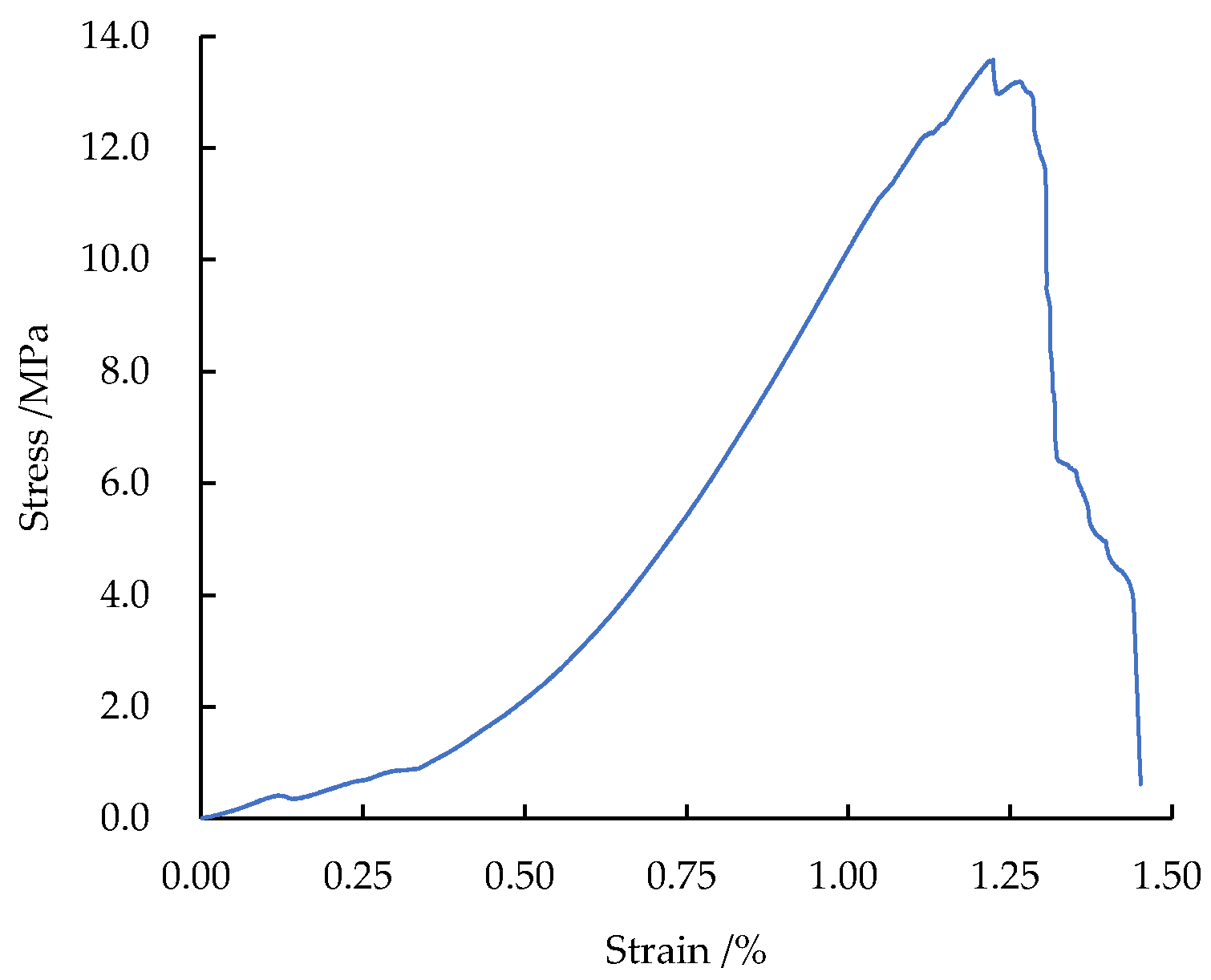
2.1. Strength Parameters of Coal

The Zhangshuanglou coal mine, located in the city of Xuzhou, Jiangsu province in China, is a typical kilometer-deep mine, and also encounters rockburst risk during excavation. The coal samples were collected from No. 9 coal seam at a roadway in No. 24 panel, with a burial depth of 850 m. The No. 9 coal seam has bursting liability testing based on the national standards on “Methods for test, monitoring and prevention of rock burst-part 2: Classification and laboratory test method on bursting liability of coal”. The results are shown in Table 1. The coal blocks were processed into 16 cuboidal specimens measuring 50 mm × 50 mm × 100 mm. Uniaxial compression tests were conducted on these coal specimens using the MTS electro-hydraulic servo test system to calibrate the physical–mechanical parameters of the model. The basic results are listed in Table 2 and the stress–strain curve for a typical coal specimen is illustrated in Figure 1.
True triaxial tests were conducted using a test system for dynamic rockburst during coal mining, customized by staff at China University of Mining and Technology. The test machine comprises a host, oil source, oil cooler, electric control cabinet, control system, an air gun, hydraulic sub-stations, and supporting accessories (including hydraulic hoses and fixtures). The design structure diagram and physical image are shown in Figure 2. The value ranges for the loads applied in three directions are shown as follows: 0~2500 kN, 0~1500 kN, and 0~1500 kN for static loads along the X, Y, and Z axes. This realized horizontal static servo-motor-controlled loading in three directions and the measurement precision met the national standard required for the mechanical testing of rocks. A total of six specimens in two groups were tested and the triaxial strength of coal under different confining pressures are listed in Table 3. The triaxial stress–strain curve and a photo after the failure of a typical specimen are shown in Figure 3. The failure mode under the true triaxial conditions was mainly shear failure and a significant large crack ran through the samples from top to bottom and, compared with uniaxial compression, the total number of cracks was relatively small, which is similar to the results by Zhao [45] and Zhong [46].
The numerical simulation software FLAC3D was adopted for the simulation. The strain-softening model was used as the constitutive model. In the strain-softening model, the values on the cohesion, internal frictional angle, and dilatancy angle of the coal model all change, albeit following different trends at yield in the coal model, so it is necessary to calibrate these parameters.
According to previous research [47], the internal frictional angle does not fluctuate to any great extent during the failure process of rocks, so it is kept constant in the present simulation process. The cohesion can be set according to the following piecewise function:
c = { c max c min ε p ε s + c max ε s < ε p c min ε s > ε p
where c max and c min separately represent the maximum and minimum cohesion, ε s is the plastic strain in coal, and ε p is the strain at which the coal enters the residual deformation stage.
According to previous research results [48], the function describing changes in the dilatancy angle with the plastic strain is shown as Equation (2):
ψ = { 1000 ψ 0.001 ε s ε s < 0.001 ψ 0.01 ψ 0.001 ψ 0.01 0.009 ε s 0.001 ε s < 0.01 ψ 0.01 ψ 0.01 ψ 0.03 0.002 ε s 0.01 ε s < 0.03 ψ 0.03 ε s < 0.001
where ψ 0.01 , ψ 0.03 , and ψ 0.001 separately correspond to the dilatancy angles when the coal has 1%, 3%, and 0.1% of plastic shear deformation.
To simulate the propagation of stress waves in the model, it requires that the grid size Δ l should not exceed 1/8 to 1/10 of the wavelength corresponding to the maximum frequency of waves.
Δ l ( 1 8 ~ 1 10 ) λ
where λ is the wavelength corresponding to the maximum frequency, and
λ = C 0 · T = C 0 f
where C 0 is the average wave velocity (4000 to 6000 m/s in most types of rock), T is the period (s), and f is the frequency (Hz).
By using a microseismic monitoring system, the frequency of the underground dynamic load is found to be lower than 70 Hz. A typical waveform is shown in Figure 4.
To study the damage characteristics of coal at different frequencies, the frequency was set to 5, 20, 40, and 60 Hz in simulation. The dynamic stress load can be calculated by Equation (5):
{ σ d p = ρ v p ( P P V ) p σ d s = ρ v s ( P P V ) s
where σ d p and σ d s are the normal and shear dynamic stress, respectively. Moreover, v p and v s are the velocity of the P-wave and S-wave. In addition, ( P P V ) p and ( P P V ) s are the peak vibration velocity of the particles, while ρ is the density of the coal seam. For instance, we have recorded a rockburst with the energy of 105 J, and the peak vibration velocity of the particles caused by the P-wave and S-wave were about 0.1 m/s and 0.2 m/s, respectively. The P-wave and S-wave velocity in this area were 4200 m/s and 2470 m/s, the average density of the surrounding rock was 2500 kg/m3, so the maximum normal and shear dynamic stress was equal to 10 MPa and 12 MPa, respectively. During numerical simulation, the stress amplitude of the dynamic load was generally set from 1 to 10 MPa.
Based on the above analysis, a model measuring 1 m × 1 m × 1 m, containing 20 × 20 × 20 elements (each measuring 5 cm × 5 cm × 5 cm) was established, which met the requirements for precision. The strain-softening model was adopted, and the dynamic load was applied to the top face of the static boundaries in the model as a sinusoidal function.

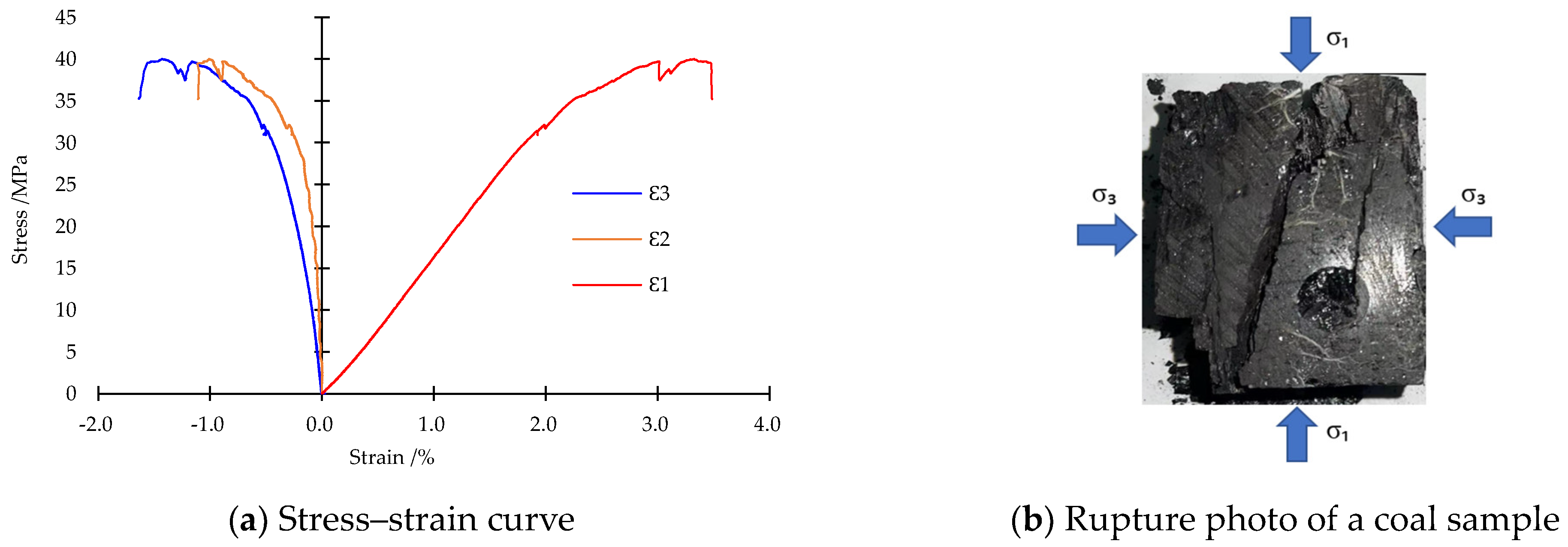
2.2. Model Verification

Figure 5 illustrates the stress–strain curves for standard specimens obtained under uniaxial compression in laboratory tests and from numerical simulation. The two stress–strain curves macroscopically remain the same shape. The elastic modulus, peak strength, and residual strength obtained in the simulation basically have the same values as those from the experiments. The difference lies in that the strain in the numerical simulation is slightly lower than that in laboratory tests, which is mainly because there is no compaction stage in the numerical model, so strain induced by compaction is absent during the whole process. The verification results indicate that the model parameters are set appropriately.

2.3. Scheme for the Test Model

Based on the mechanical properties of coal obtained in the laboratory, the FLAC3D numerical model was adopted to simulate the damage and failure trends of coal subjected to the true triaxial stress path, as shown in Figure 6. In the research, the static loads parallel and vertical to the direction for applying the dynamic load were defined as the axial static load and the static confining pressure, respectively. The test scheme can be described as follows: the initial static load was applied to the model; after the computation reached equilibrium, the dynamic load was applied together with axial loading to failure. Three conditions were studied (Table 4), wherein the influences of the static loads on the damage to coal were mainly studied under Conditions 1 and 2; the damage to coal under different parameters of dynamic load was mainly investigated under Condition 3.
In FLAC3D, the fish programming language is used to calculate the volume of the plastic zones in the model. The degree of damage is represented by the volume of the plastic zones and the damage variable D is expressed as follows:
D = V s n V s z
where V s n is the current volume of the plastic zones in the model, and V s z denotes the volume of the plastic zones in the model after the disturbance and failure of the model.

3. Influences of Static Loads on the Damage to Coal

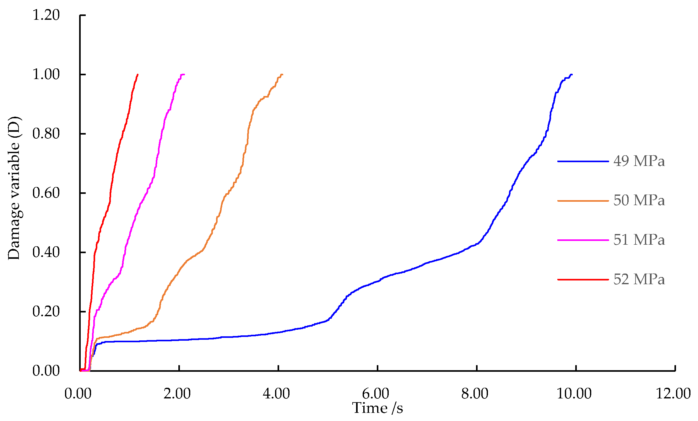
3.1. Influences of Axial Static Load on the Damage to Coal

Following Condition 1 in Table 4, different initial axial static pressures from 42 MPa (according to Table 3, which is about 75% of the strength of the coal under the applied confining pressure) to 52 MPa were applied to the coal specimens, followed by the application of dynamic load with an amplitude of 4 MPa at a frequency of 20 Hz, under the fixed confining pressures (8 and 12 MPa). The model tests show that when the initial axial static pressure reaches 77% of the compressive strength, namely 43 MPa, the coal yields and plastic zones develop therein under the dynamic load, while it is not damaged sufficiently to cause failure. Only when the initial axial static pressure reaches 89% of the compressive strength, that is 49 MPa, is the coal disturbed and damaged under the dynamic load. This indicates that the coal has a yield threshold and a disturbance threshold of the initial axial static pressure under the dynamic load, which are separately 43 and 49 MPa under the test conditions.
The evolution of the plastic zones during dynamic–static loading until the failure of the coal under different initial axial static loads is illustrated in Figure 7. As the initial axial static load grows, the volume of the plastic zones in the coal after applying the dynamic load also tends to increase. When the initial axial static load is lower than the failure threshold, the fitting curve for the volume of the plastic zones is a quadratic function; thus, as the initial axial static load exceeds the failure threshold, the fitting curve becomes an exponential function. That is, the total volume and volume increment of the plastic zones in the coal both increase when increasing the initial axial static pressure. The typical stress distribution and plastic zones are shown in Figure 8.
Under different axial static loads, the damage evolution of which is displayed in Figure 9, the damage variable shows step-like growth when the strain begins to increase. In addition, the larger the initial axial static load is, the more the elastic energy stored in the sample before the dynamic load is applied, the greater the energy released during failure, and the faster the growth of the damage variable. When the initial axial static pressure is 49 MPa, the growth of the damage variable is 0.08, which reaches 0.4 at 52 MPa. Thereafter, the rate of growth in the damage variable gradually decreases as the strain increases. The larger the initial axial static pressure, the smaller the strain at failure in the coal. As the initial axial static load is increased from 49 to 52 MPa, the strain at failure of the coal reduces from 0.9% to 0.3%, that is the dynamic load renders the coal more prone to brittle failure under the high static load.

3.2. Influences of Confining Pressure on the Damage to Coal

Combinations of different confining pressures were applied along the X and Y axes of the coal model. The dynamic load was applied on the top face and the yield threshold and failure threshold of the model under different conditions were recorded. Figure 10 illustrates the influences of the minimum and intermediate principal stresses on the plastic zones. The figure shows that as the minimum principal stress increases, the damage caused by the dynamic load is weakened, the appearance time of the plastic zones is gradually delayed, and the fitting curve for the volume of the plastic zones is a logarithmic function, shown as the red curve in Figure 10a. This indicates that the minimum principal stress can significantly inhibit the damage caused by the dynamic load. In comparison, as the intermediate principal stress increases, the volume of the plastic zones in the coal reduces, but the attenuation amplitude is small, the fitting curve is a linear function, shown as the purple line in Figure 10b, and the volume of the plastic zones changes uniformly with the intermediate principal stress. The comparison reveals that the damage caused by the dynamic load is weakened either as the minimum or intermediate principal stress on the coal is increased, and the minimum principal stress inhibits the damage to a greater extent.

4. Damage Caused by the Dynamic Load

4.1. Influences of the Amplitude of the Dynamic Load on Damage Evolution

Based on aforementioned simulations, coal is damaged much more significantly under dynamic–static combined loading with high static loads. Therefore, when studying the influences of the dynamic load on damage, the confining pressures were set to 16 and 18 MPa, under which the strength of coal was about 99 MPa, as revealed by the numerical model tests. Changes in the amplitude of the dynamic load were separately set to 2.5% (2.475 MPa), 5% (4.95 MPa), 7.5% (7.425 MPa), and 10% (9.9 MPa) of the peak strength, while keeping the frequency of the dynamic load constant at 20 Hz.
After the same period of dynamic loading at different amplitudes, the variation of the plastic zones and its fitting curve are illustrated in Figure 11. With the increasing amplitude of the dynamic load, the volume of the plastic zones enlarges after the same amount of time, and the curve representing the variation in the volume of the plastic zones with the amplitude is exponential, i.e., when increasing the dynamic load by a given amount, the greater the original amplitude of the dynamic load, the more severe the damage in the model. When the amplitude of the dynamic load exceeds 7.5% of the compressive strength, the damage caused by the dynamic load is more severe.
The result shows that the larger the amplitude of the dynamic load, the more intense the damage to the coal and the shorter the time required to cause that damage. In the meantime, the development time and volume of the plastic zones are interlocked: the larger the volume of the plastic zones, the shorter the development time. The rapid expansion of the plastic zones is generally accompanied by a rockburst. Therefore, if there are ultra-thick hard roofs and dynamic load sources of large-scale active faults in coal mines, weakening or eliminating dynamic load sources has become the primary measure to prevent rockburst.
Figure 12 shows the relationships of the damage variable and strain of coal under dynamic load at different amplitudes. The figure reveals that, with increasing amplitude, the initial damage variable constantly increases and the strain corresponding to complete damage decreases. This is because the greater the amplitude is, the more intense the damage effect of the dynamic load and the smaller the time of the dynamic loads that can be borne by the model. The strain when the damage factor is about 84% can be used as the residual strain, expressed by ε 1 , ε 2 , and ε 3 . It can be seen that ε 1 < ε 2 < ε 3 , which indicates that the residual strain of coal constantly decreases with the increasing amplitude. This is because the strength is reduced by a greater amount and the residual strength is also lower after microstructural units are subjected to the damage caused by the stress waves with greater energy. In the roadway of a coal mine, if the coal seam undergoes rockburst failure triggered by dynamic load, the kinetic energy of the coal blocks would increase with the rise in the amplitude of the dynamic load, similar rules also evinced by previous research results [49].

4.2. Amplitude Attenuation of the Dynamic Load with Changes in the Frequency of the Dynamic Load

The confining pressures on the model were set to 18 and 16 MPa, while the dynamic load had an amplitude of 4.95 MPa and frequencies of 5, 20, 40, and 60 Hz, and only the frequency of the dynamic load was changed.
As the frequency increases from 5 to 60 Hz, the volume of the plastic zones fluctuates (first decreasing, then increasing, and reducing again), which indicates that the damage under the dynamic load fluctuates as the frequency increases. It is worth noting that when the frequency is 5 Hz, the volume of the plastic zones is largest. This is because 5 Hz approximate to the intrinsic frequency of the model, at which the dynamic load exerts significant damage and excitation effects on the grid. As a result, static grids in the model change to dynamic ones, accompanied by high-speed synchronous vibrations, which facilitate the development and propagation of damage in the model.
Figure 13 shows a schematic diagram of the damage caused by the dynamic load at different frequencies. The damage caused by resonance is reduced as the frequency increases. This is because the higher the frequency, the greater the difference in the resonant frequency and, therefore, the weaker the damage and excitation effects induced by the resonance. Moreover, the damage caused by stress waves is enhanced with increasing frequency because the higher the frequency, the more stable the stress propagation and the greater the stress on the coal. The superimposed damage effect on coal fluctuates due to the asynchronous variation in the two factors, this explains why the volume of the plastic zones in the model (Figure 11) are subject to fluctuations with increasing frequency.
Figure 14 shows the relationship between the damage variable for coal and time at different frequencies: at a frequency of 5 Hz, the curves rise near vertically in the initial stage, while the slopes remain relatively high even though they reduce to some extent in the mid and late stages. This suggests that the plastic zones enlarge explosively in the initial development stage under the dynamic load at a frequency of 5 Hz, and remain subject to rapid expansion throughout. At a frequency of 20 Hz, the curves are shallow in the early stage of development, and the slopes are relatively low in the late stage, despite increasing somewhat. This means that the plastic zones are mainly formed in the late stage and their development is slow under the frequency of 20 Hz. As the frequency increases to 40 Hz, the damage variable increases in a step-like manner indicating that the plastic zones are mainly formed in the early and late stages. Meanwhile, t 1 , t 2 , and t 3 in the figure correspond to the total development time of the plastic zones in the model under the dynamic loads at frequencies of 5, 20, and 40 Hz. It can be seen that t 1 < t 3 < t 2 , which suggests that the development time of the plastic zones is interlocked with the volume of the plastic zones, that is the larger the plastic zones, the faster their development.
If plastic zones in coal are formed statically or quasi-statically, they will not trigger dynamic rockburst disasters in the surrounding rock; if plastic zones expand and develop rapidly, they may generate rockburst in the coal. The above analysis reveals that when coal is resonant under dynamic load, more plastic zones develop in the coal (and they do so rapidly), providing favorable conditions for the development of impact disasters therein.

4.3. Mechanism of Influence of the Dynamic Load Parameters on the Damage to Coal

The damage and failure of coal under static–dynamic combined stress conditions are mainly related to the stress state. Assuming that the static principal stress at a certain particle is σ s and the dynamic stress is σ d , expressed as Equations (7) and (8), respectively:
σ s = [ σ s 1 0 0 σ s 2 ]
σ d = [ σ d 1 ( t ) τ d ( t ) τ d ( t ) σ d 2 ( t ) ]
So, the stress state can be obtained as Equation (9):
σ = [ σ s 1 + σ d 1 ( t ) τ d ( t ) τ d ( t ) σ s 2 + σ d 2 ( t ) ]
and the principal stress at this point becomes:
σ p 1 , p 2 = σ s 1 + σ s 2 + σ d 1 ( t ) + σ d 2 ( t ) 2 ± [ σ s 1 σ s 2 + σ d 1 ( t ) σ d 2 ( t ) ] 2 4 + τ d ( t ) 2
One can obtain the rotation angle for the axis of principal stress under the static–dynamic combination as Equation (11):
θ p = 1 2 arctan 2 τ d ( t ) σ 1 σ 3 + σ d 1 ( t ) σ d 3 ( t )
where τ d ( t ) is the shear stress component formed by the dynamic load, and σ d 1 ( t ) and σ d 3 ( t ) separately represent the normal stress components of the dynamic load.
Under dynamic load, the direction of principal stress constantly rotates with time and the change is mainly related to the principal stress difference between static and dynamic loads. The greater and the wider the range of the dynamic load, the larger range of rotation of the axes of principal stresses. Therefore, under dynamic–static combined loading, dynamic load plays a role in changing the stress (in terms of both the magnitude and direction). When the magnitude of the stress is changed, cracks over a wider range of angles can reach the critical stress and, therefore, propagate. With the rotation of the principal stress axes, the dominant direction also rotates, so that cracks propagate in more directions, thus damaging the coal. After the action of dynamic load, many cracks in the coal have propagated and their length has increased, the critical stress for propagation decreases. In the meantime, because of the increase in the damage factor, the critical crack length decreases, therefore, after the dynamic load, cracks in the coal will further propagate under static load to damage the coal until dynamic failure. It can be concluded that static loads lay the stress foundation, while dynamic load triggers crack propagation under the combination of dynamic and static loads.

5. Weights of Different Load Parameters for Damage to Coal

5.1. Entropy Weight Method and the Weight Assignment Process

The simulation results can only determine the influences of a single factor on the damage to coal, while it is hard to determine the weights of each factor in influencing the damage and deterioration of coal. The entropy weight method has been applied to predict rockburst, so it was used to calculate the weights of the minimum principal stress, the maximum principal stress, the amplitude of the dynamic load, and the frequency of dynamic load. Due to the low influences of intermediate principal stress on the damage to coal, its weight was not calculated.
The first step in the entropy weight method is data normalization. At first, the data are classified as either positive or negative indices (factors that facilitate the damage effect of dynamic load are taken as positive factors) and the normalization equation is expressed as:
{ x i j = x i j min ( x i j ) max ( x i j ) min ( x i j )     ( Positive   indicators ) x i j = max ( x i j ) x i j max ( x i j ) min ( x i j )     ( Negative   indicators )
Step 2 entails calculation of the weights for the j th index under the i th condition using the following formula:
Y i j = x i j i m x i j
Step 3 entails calculation of the information entropy of the indices using the following formula:
e j = k i = 1 m ( Y i j ln Y i j )
where m is the number of data sets used for the assessment; k is expressed as follows:
k = 1 / ln m
Step 4 entails calculation of the redundancy of information entropy using the following formula:
d j = 1 e j
Step 5 entails calculation of the weights of the indices using the following formula:
W j = d j / j = 1 n d j
where n represents the number of indices.

5.2. Weight Calculation Results

A total of 24 data sets at failure in the established model due to the dynamic load were selected and the aforementioned formulae were used to calculate the weights using the entropy weight method, as shown in Table 5.
Table 5 shows various factors listed in descending order according to their weights, namely the minimum principal stress, maximum principal stress, amplitude of the dynamic load, and frequency of the dynamic load. When reserving one decimal fraction, their weights are 29.1%, 28.9%, 24.3%, and 17.7%, respectively. The weights of the minimum and maximum principal stresses differ slightly. This indicates that although the vibration effect of the dynamic load may exacerbate the damage, the most important factor remains the static load. Damage caused by the dynamic load is significant or not determined as to whether it exceeds the failure threshold. And the threshold values are also to a large extent determined by the values of the confining pressure and axial static load. Therefore, the static load has a greater weight in terms of its damaging effect on coal. The research shows that altering the frequency of the dynamic load will cause fluctuating changes in the damaging effect. However, it is difficult to control the natural frequency and predict the frequencies of the load sources in practice. Considering this, the following measures were proposed to inhibit rockburst induced by superimposed dynamic and static loads:
(1)
The measures to prevent rockburst should be prioritized as follows: increasing the minimum principal stress, reducing the maximum principal stress, and decreasing the amplitude of the dynamic load;
(2)
Dynamic load induced rockburst can be avoided by either effective stress relief to reduce the abutment pressures on surrounding rocks or reasonable support to increase the minimum principal stress on the surrounding rock.
For artificial dynamic load sources, including excavation and blasting, measures including decelerating the rate of mining at coal seams and using low-charge multi-hole blasting can be used to reduce the rockburst risk.

6. Discussion and Conclusions

(1)
The larger the initial axial static load (the maximum principal stress), the faster the increase in the damage variable under dynamic load and the greater the tendency to brittle failure. The confining pressures (intermediate and minimum principal stresses) inhibit the dynamic disturbance to the coal.
(2)
With increasing amplitude of the dynamic load, the volume of the plastic zones in coal grows exponentially, while the residual strength of the coal constantly decreases, which increases the risk of rockburst and enhances the intensity of a rockburst.
(3)
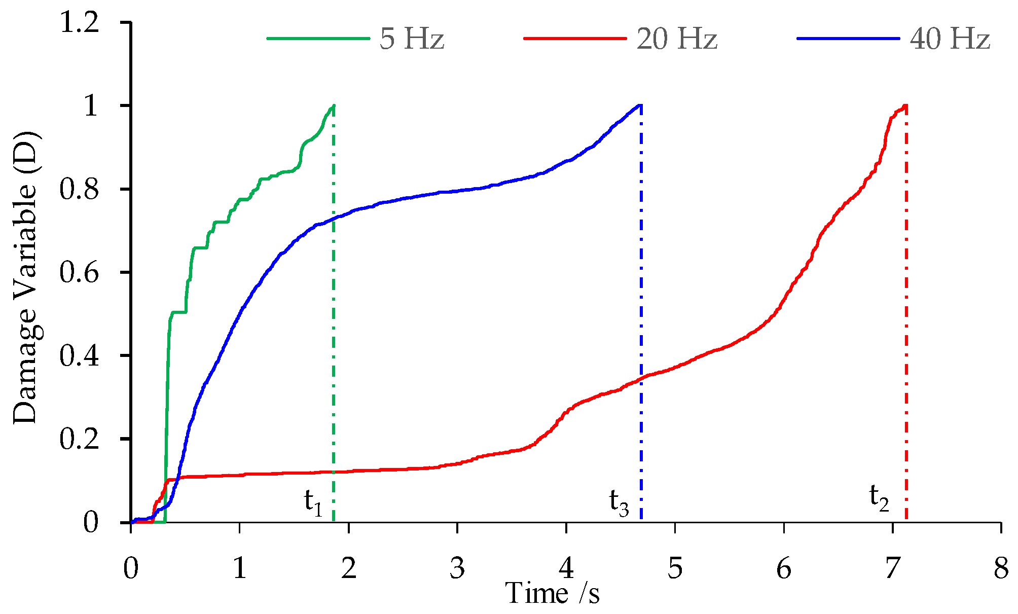
The damage and deterioration effects of dynamic load on coal fluctuate with the rising frequency. In addition, when the dynamic load is applied to coal to induce resonance, the damage variable increases in a quasi-linear manner with time: the dynamic load exerts the strongest damage and is most likely to induce a rockburst.
(4)
Under dynamic load, the time taken for the development of the plastic zones is interlocked with the volume of the plastic zones, that is the greater the volume of the plastic zones, the faster their development.
(5)
For the minimum principal stress, maximum principal stress, amplitude of the dynamic load, and frequency of the dynamic load, their weights on the deterioration and damage effects on coal decrease in succession. Increasing the confining pressure on the rock surrounding the roadways and reducing the abutment pressure can prevent impact failure of the rock surrounding a roadway.

Author Contributions

Conceptualization, H.H.; methodology, S.G.; data curation, X.L.; software, Z.M. All authors have read and agreed to the published version of the manuscript.

Funding

This research was funded by the State Key Research Development Program of China (Grant No. 2022YFC3004605), the National Natural Science Foundation of China (No. 51974302; 52274147), and the Fundamental Research Funds for the Central Universities (No. 2013QNB30).

Data Availability Statement

The data used for conducting the classifications are available from the corresponding author upon request.

Conflicts of Interest

The authors declare no conflict of interest.

References

  1. Dou, L.M.; Tian, X.X.; Cao, A.Y.; Gong, S.Y.; He, H.; He, J.; Cai, W.; Li, X.W. Present situation and problems of coal mine rock burst prevention and control in China. J. China Coal Soc. 2022, 47, 152–171. [Google Scholar]
  2. Zhang, C.; Canbulat, I.; Hebblewhite, B.; Ward, C.R. Assessing coal burst phenomena in mining and insights into directions for future research. Int. J. Coal Geol. 2017, 179, 28–44. [Google Scholar] [CrossRef]
  3. Wu, M.; Ye, Y.; Wang, Q.; Hu, N. Development of Rockburst Research: A Comprehensive Review. Appl. Sci. 2022, 12, 974. [Google Scholar] [CrossRef]
  4. Yuan, L. Risk identification, monitoring and early warning of typical coal mine dynamic disasters during the 13th Five-Year Plan period. J. Min. Sci. Technol. 2021, 6, 1–8. [Google Scholar]
  5. He, H.; Dou, L.; Gong, S.; He, J.; Zheng, Y.; Zhang, X. Microseismic and electromagnetic coupling method for coal bump risk assessment based on dynamic static energy principles. Saf. Sci. 2019, 114, 30–39. [Google Scholar] [CrossRef]
  6. Du, K.; Tao, M.; Li, X.; Zhou, J. Experimental Study of Slabbing and Rockburst Induced by True-Triaxial Unloading and Local Dynamic Disturbance. Rock Mech. Rock Eng. 2016, 49, 3437–3453. [Google Scholar] [CrossRef]
  7. Li, X.; Gong, F.; Tao, M.; Dong, L.; Du, K.; Ma, C.; Zhou, Z.; Yin, T. Failure mechanism and coupled static-dynamic loading theory in deep hard rock mining: A review. J. Rock Mech. Geotech. 2017, 9, 767–782. [Google Scholar] [CrossRef]
  8. Ren, F.; Zhu, C.; He, M.; Shang, J.; Feng, G.; Bai, J. Characteristics and Precursor of Static and Dynamic Triggered Rockburst: Insight from Multifractal. Rock Mech. Rock Eng. 2023, 56, 1945–1967. [Google Scholar] [CrossRef]
  9. Ma, Z.; Yan, P.; Cheng, S.; Gong, P.; Qi, F.; Wang, J. Experimental study of the dynamic mechanical responses and failure characteristics of coal under true triaxial confinements. Int. J. Min. Sci. Technol. 2023, 33, 761–772. [Google Scholar] [CrossRef]
  10. Zhou, Y.; Sheng, Q.; Li, N.; Fu, X. The Dynamic Mechanical Properties of a Hard Rock Under True Triaxial Damage-Controlled Dynamic Cyclic Loading with Different Loading Rates: A Case Study. Rock Mech. Rock Eng. 2022, 55, 2471–2492. [Google Scholar] [CrossRef]
  11. Deng, J. Analytical and numerical investigations on pillar rockbursts induced by triangular blasting waves. Int. J. Rock Mech. Min. 2021, 138, 104518. [Google Scholar] [CrossRef]
  12. Li, X.; Gong, F. Research progress and prospect of deep mining rock mechanics based on coupled static-dynamic loading testing. J. China Coal Soc. 2021, 46, 846–866. [Google Scholar]
  13. Feng, X.; Ding, Z.; Ju, Y.; Zhang, Q.; Ali, M. “Double Peak” of Dynamic Strengths and Acoustic Emission Responses of Coal Masses Under Dynamic Loading. Nat. Resour. Res. 2022, 31, 1705–1720. [Google Scholar] [CrossRef]
  14. Dou, L.; Bai, J.; Li, X.; He, H. Study on prevention and control technology of rockburst disaster based on theory of dynamic and static load. Coal Sci. Technol. 2018, 46, 1–8. [Google Scholar]
  15. Cai, W.; Dou, L.; Si, G.; Hu, Y. Fault-Induced Coal Burst Mechanism under Mining-Induced Static and Dynamic Stresses. Engineering 2021, 7, 687–700. [Google Scholar] [CrossRef]
  16. Wang, C.; Cao, A.; Zhang, C.; Canbulat, I. A New Method to Assess Coal Burst Risks Using Dynamic and Static Loading Analysis. Rock Mech. Rock Eng. 2020, 53, 1113–1128. [Google Scholar] [CrossRef]
  17. Cai, W.; Bai, X.; Si, G.; Cao, W.; Gong, S.; Dou, L. A Monitoring Investigation into Rock Burst Mechanism Based on the Coupled Theory of Static and Dynamic Stresses. Rock Mech. Rock Eng. 2020, 53, 5451–5471. [Google Scholar] [CrossRef]
  18. Haimson, B. True Triaxial Stresses and the Brittle Fracture of Rock. Pure Appl. Geophys. 2006, 163, 1101–1130. [Google Scholar] [CrossRef]
  19. Alexeev, A.D.; Revva, V.N.; Bachurin, L.L.; Prokhorov, I.Y. The effect of stress state factor on fracture of sandstones under true triaxial loading. Int. J. Fract. 2008, 149, 1–10. [Google Scholar] [CrossRef]
  20. Lee, H.; Haimson, B.C. True triaxial strength, deformability, and brittle failure of granodiorite from the San Andreas Fault Observatory at Depth. Int. J. Rock Mech. Min. 2011, 48, 1199–1207. [Google Scholar] [CrossRef]
  21. Kwaśniewski, M. Comments on the ISRM Suggested Method “A Failure Criterion for Rocks Based on True Triaxial Testing”. Rock Mech. Rock Eng. 2013, 46, 917–919. [Google Scholar] [CrossRef] [Green Version]
  22. Baizhanov, B.; Katsuki, D.; Tutuncu, A.N.; Mese, A.I. Experimental Investigation of Coupled Geomechanical, Acoustic, and Permeability Characterization of Berea Sandstone Using a Novel True Triaxial Assembly. Rock Mech. Rock Eng. 2019, 52, 2491–2503. [Google Scholar] [CrossRef]
  23. Shirani Faradonbeh, R.; Taheri, A.; Ribeiro e Sousa, L.; Karakus, M. Rockburst assessment in deep geotechnical conditions using true-triaxial tests and data-driven approaches. Int. J. Rock Mech. Min. 2020, 128, 104279. [Google Scholar] [CrossRef]
  24. Duan, M.; Jiang, C.; Yin, W.; Yang, K.; Li, J.; Liu, Q. Experimental study on mechanical and damage characteristics of coal under true triaxial cyclic disturbance. Eng. Geol. 2021, 295, 106445. [Google Scholar] [CrossRef]
  25. Mogi, K. How I developed a true triaxial rock testing machine. In True Triaxial Testing of Rocks; Kwasniewski, M., Li, X., Takahashi, M., Eds.; International Workshop on the True Triaxial Testing of Rocks (TTT); CRC Press: Boca Raton, FL, USA, 2012; Volume 4, pp. 139–157. [Google Scholar]
  26. Yin, G.; Li, M.; Xu, J.; Wang, W.; Li, W.; Li, X.; Song, Z.; Deng, B. A New Multi-Functional True Triaxial Fluid-Solid Coupling Experiment System and Its Application. Chin. J. Rock Mech. Eng. 2015, 34, 2436–2445. [Google Scholar]
  27. Tao, M.; Li, X.; Wu, C. 3D numerical model for dynamic loading-induced multiple fracture zones around underground cavity faces. Comput. Geotech. 2013, 54, 33–45. [Google Scholar]
  28. Yoshida, S. Numerical Simulations of Earthquake Triggering by Dynamic and Static Stress Changes Based on a Revised Friction Law. J. Geophys. Res. Solid Earth 2018, 123, 4109–4122. [Google Scholar] [CrossRef]
  29. Wu, X.; Jiang, L.; Xu, X.; Guo, T.; Zhang, P.; Huang, W. Numerical analysis of deformation and failure characteristics of deep roadway surrounding rock under static-dynamic coupling stress. J. Cent. South Univ. 2021, 28, 543–555. [Google Scholar] [CrossRef]
  30. Foroutan, T.; Mirghasemi, A.A. Use of CFD-DEM to evaluate the effect of intermediate stress ratio on the undrained behaviour of granular materials. Adv. Powder Technol. 2022, 33, 103507. [Google Scholar]
  31. Li, X.; Weng, L. Numerical investigation on fracturing behaviors of deep-buried opening under dynamic disturbance. Tunn. Undergr. Space Technol. 2016, 54, 61–72. [Google Scholar] [CrossRef]
  32. Zhu, W.C.; Li, Z.H.; Zhu, L.; Tang, C.A. Numerical simulation on rockburst of underground opening triggered by dynamic disturbance. Tunn. Undergr Space Technol. 2010, 25, 587–599. [Google Scholar] [CrossRef]
  33. Zhou, X.; Zhang, D.; Nowamooz, H.; Jiang, C.; Ye, C. Investigation on Damage and Failure Mechanisms of Roadway Surrounding Rock Triggered by Dynamic–Static Combined Loads. Rock Mech. Rock Eng. 2022, 55, 5639–5657. [Google Scholar] [CrossRef]
  34. Yang, J.H.; Yao, C.; Jiang, Q.H.; Lu, W.B.; Jiang, S.H. 2D numerical analysis of rock damage induced by dynamic in-situ stress redistribution and blast loading in underground blasting excavation. Tunn. Undergr. Space Technol. 2017, 70, 221–232. [Google Scholar] [CrossRef]
  35. Wang, L.; Cao, A.; Dou, L.; Guo, W.; Zhang, Z.; Zhi, S.; Zhao, Y. Numerical simulation on failure effect of mining-induced dynamic loading and its influential factors. Saf. Sci. 2019, 113, 372–381. [Google Scholar] [CrossRef]
  36. Manouchehrian, A.; Cai, M. Analysis of rockburst in tunnels subjected to static and dynamic loads. J. Rock Mech. Geotech. 2017, 9, 1031–1040. [Google Scholar] [CrossRef]
  37. Li, X.F.; Zhang, Q.B.; Li, H.B.; Zhao, J. Grain-Based Discrete Element Method (GB-DEM) Modelling of Multi-scale Fracturing in Rocks Under Dynamic Loading. Rock Mech. Rock Eng. 2018, 51, 3785–3817. [Google Scholar] [CrossRef]
  38. Aziznejad, S.; Esmaieli, K.; Hadjigeorgiou, J.; Labrie, D. Responses of jointed rock masses subjected to impact loading. J. Rock Mech. Geotech. 2018, 10, 624–634. [Google Scholar] [CrossRef]
  39. Gao, F.; Kaiser, P.K.; Stead, D.; Eberhardt, E.; Elmo, D. Strainburst phenomena and numerical simulation of self-initiated brittle rock failure. Int. J. Rock Mech. Min. 2019, 116, 52–63. [Google Scholar] [CrossRef]
  40. Yang, J.; Liu, K.; Li, X.; Liu, Z. Stress initialization methods for dynamic numerical simulation of rock mass with high in-situ stress. J. Cent. South Univ. 2020, 27, 3149–3162. [Google Scholar] [CrossRef]
  41. Li, S.; Chen, Z.; Li, W.; Yan, T.; Bi, F.; Tong, Y. An FE Simulation of the Fracture Characteristics of Blunt Rock Indenter Under Static and Harmonic Dynamic Loadings Using Cohesive Elements. Rock Mech. Rock Eng. 2023, 56, 2935–2947. [Google Scholar] [CrossRef]
  42. Asadi, P.; Fakhimi, A. Bonded particle modeling of grain size effect on tensile and compressive strengths of rock under static and dynamic loading. Adv. Powder Technol. 2023, 34, 104013. [Google Scholar] [CrossRef]
  43. Feng, P.; Wei, M.; Dai, F.; Tang, R.; Qiu, H.; Gong, J. DEM investigation on the mechanical behaviors of flawed specimens subjected to coupled static-dynamic loads. Soil Dyn. Earthq. Eng. 2020, 135, 106220. [Google Scholar] [CrossRef]
  44. Yang, Y.; Guo, H.; Fu, X.; Zheng, H. Boundary settings for the seismic dynamic response analysis of rock masses using the numerical manifold method. Int. J. Numer. Anal. Methods 2018, 42, 1095–1122. [Google Scholar] [CrossRef]
  45. Zhao, W.; Xie, P.; Chen, W.; Gao, H. Mechanical behaviour of rock containing a persistent joint under uniaxial compression at different strain rates. Eur. J. Environ. Civ. Eng. 2023. [Google Scholar] [CrossRef]
  46. Zhong, K.; Zhao, W.; Qin, C.; Gao, H.; Chen, W. Mechanical Properties of Roof Rocks under Superimposed Static and Dynamic Loads with Medium Strain Rates in Coal Mines. Appl. Sci. 2021, 11, 8973. [Google Scholar] [CrossRef]
  47. Jin, J.; She, C.; Shang, P. Study on strength parameters and dilation angle evolution models in hard rock elastic-plastic deformation and failure process. Rock Soil Mech. 2019, 40, 4401–4411. [Google Scholar]
  48. Wang, Y.; Gong, J.; Chen, Z. Deformation characteristics and dilatancy model of coal rock under different confining pressures. Hydrogeol. Eng. Geol. 2015, 42, 106–111. [Google Scholar]
  49. Gong, F.; Si, X.; Li, X.; Wang, S. Dynamic triaxial compression tests on sandstone at high strain rates and low confining pressures with split Hopkinson pressure bar. Int. J. Rock Mech. Min. 2019, 113, 211–219. [Google Scholar] [CrossRef]
Figure 1. Stress–strain curve for a typical coal specimen.
Minerals 13 00956 g001
Figure 2. The design structure diagram and realistic image of the testing system.
Minerals 13 00956 g002
Figure 3. Stress–strain curve and photo of a typical coal specimen in true triaxial tests.
Minerals 13 00956 g003
Figure 4. Waveform and spectrum of a typical mining tremor.
Minerals 13 00956 g004
Figure 5. Comparison between the numerical simulation and laboratory tests.
Minerals 13 00956 g005
Figure 6. Stress path of the simulation model.
Minerals 13 00956 g006
Figure 7. Influences of the initial axial static stress on the evolution of the plastic zones. (a) The initial axial static pressure is lower than the failure threshold (49 MPa); (b) the initial axial static pressure is larger than the failure threshold (49 MPa).
Minerals 13 00956 g007
Figure 8. Typical stress distribution and plastic zones.
Minerals 13 00956 g008
Figure 9. Influences of the initial axial static load on the evolution of damage.
Minerals 13 00956 g009
Figure 10. Influences of the confining pressure on the evolution of the plastic zones. (a) Influences of the minimum principal stress on the development of the plastic zones; (b) influences of the intermediate principal stress on the development of the plastic zones.
Minerals 13 00956 g010
Figure 11. Influences of the amplitude of the dynamic load on damage evolution. (a) Volume of the plastic zones under the amplitude of the dynamic loads; (b) time of the damage variable under the amplitude of the dynamic loads.
Minerals 13 00956 g011
Figure 12. Relationship between the strain and damage variable.
Minerals 13 00956 g012
Figure 13. Schematic representation of the damage under the dynamic load at different frequencies.
Minerals 13 00956 g013
Figure 14. Relationship between the damage variable and time at different dynamic frequencies.
Minerals 13 00956 g014
Table 1. Results of bursting liability for No.9 coal seam.
IndexTesting Result
Duration of Dynamic Fracture
DT/ms
Elastic Strain Energy Index
WET
Bursting Energy Index
KE
Uniaxial Compressive Strength
Rc/MPa
CategoryLevel
5704.9234.59614.82IIWeak
Table 2. Mechanical parameters of the coal specimens.
Uniaxial Compressive Strength/MPaPoisson’s RatioElastic Modulus/GPaCohesion/MPaInternal Frictional Angle/°
8.400.210.882.440
Table 3. True triaxial compressive strengths of the coal specimens.
Serial Numbers σ 3 / MPa σ 2 / MPa Mean Peak Strength/MPa
14641.13
281255.6
Table 4. Simulation experiments.
ConditionsInitial Static LoadsDynamic Load
σ3/MPaσ2/MPaσ1/MPaAmplitude/MPaFrequency/Hz
181242–52420
24–204–20Loading to failure2–1020
34–204–20Loading to failure1–105–60
Table 5. Calculation results of the entropy weight method.
Indices σ 1   ( MPa ) σ 3   ( MPa ) Δ σ   ( MPa ) Frequency (Hz)
Conditions1 (Positive)−1 (Negative)1 (Positive)−1 (Negative)
S-13762.155
S-24182.1520
S-34162.1540
S-44262.1560
S-584124.955
S-694144.9520
S-794164.9540
S-895164.9560
S-94361.07520
S-104182.1540
S-1139103.22520
S-123764.320
S-1399162.47540
S-1494164.9560
S-1591147.4520
S-1688169.920
S-172942.320
S-183963.1740
S-19498460
S-2059104.9520
S-2169125.820
S-2280146.5720
S-2391167.440
S-24101188.320
Information entropy0.9130554230.9122748860.9269431460.946807107
Information redundancy0.0869445770.0877251140.0730568540.053192893
Weight0.2889297460.2915235860.242778780.176767887
Disclaimer/Publisher’s Note: The statements, opinions and data contained in all publications are solely those of the individual author(s) and contributor(s) and not of MDPI and/or the editor(s). MDPI and/or the editor(s) disclaim responsibility for any injury to people or property resulting from any ideas, methods, instructions or products referred to in the content.

