
Characterization of Compacted Ca- and Na-Bentonite with Copper Corrosion Products in the KAERI Underground Research Tunnel


Abstract
1. Introduction
2. Materials and Methods
2.1. Sample
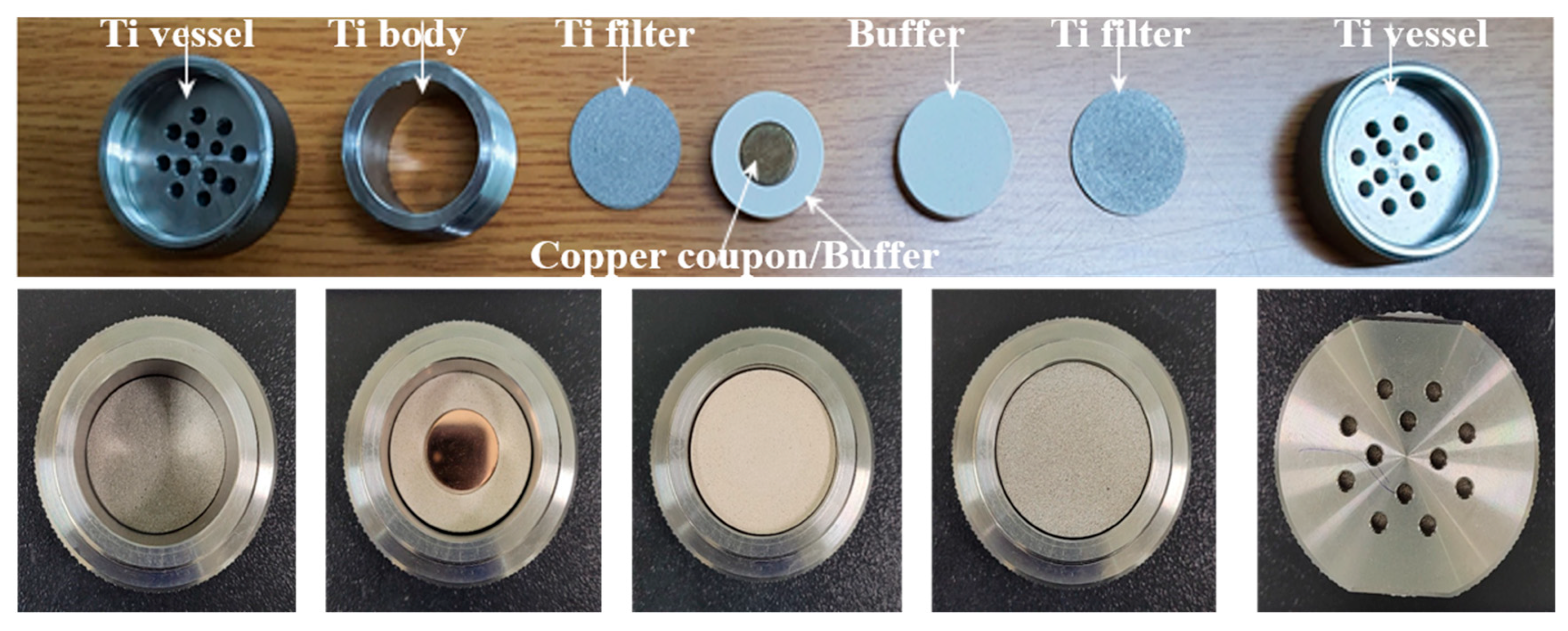
2.2. Corrosion Cell Using the Long-Term In Situ Experiment
2.3. KURT Groundwater
2.4. Geochemical Analysis of Solid Samples
2.5. Mineralogical Analysis
2.6. Cu Corrosion Analysis
3. Results
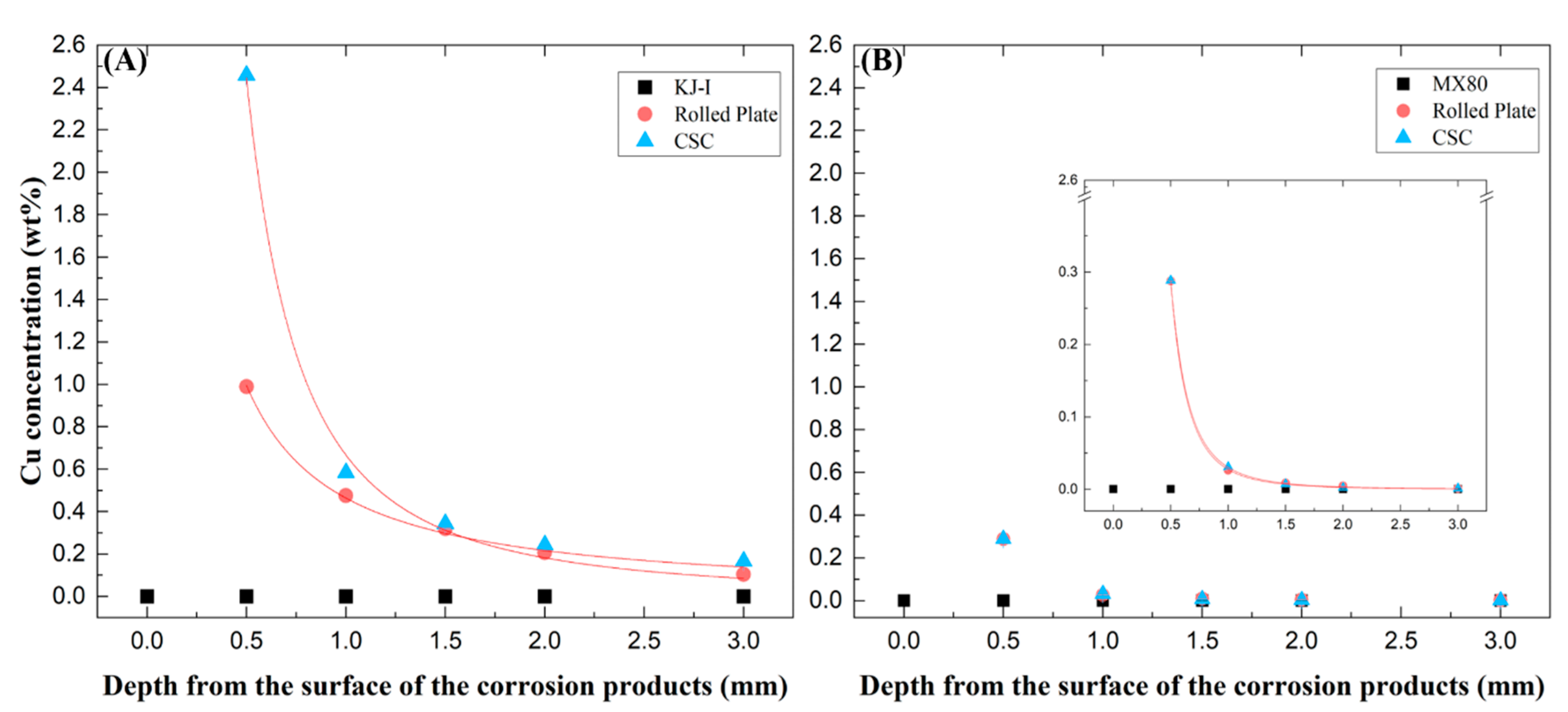
3.1. Cu Corrosion
3.2. Geochemistry of the Solid Samples
3.3. Mineralogy
4. Discussion
5. Conclusions
Author Contributions
Funding
Data Availability Statement
Acknowledgments
Conflicts of Interest
References
- Dohrmann, R.; Kaufhold, S. Cation exchange and mineral reactions observed in MX80 buffer samples of the prototype repository in situ experiment in ASPO Sweden. Clays Clay Miner. 2014, 62, 357–373. [Google Scholar] [CrossRef]
- Hadi, J.; Wersin, P.; Serneels, V.; Greneche, J.M. Eighteen years of steel-bentonite interaction in the FEBEX in situ test at the Grimsel Test Site in Switzerland. Clays Clay Miner. 2019, 67, 111–131. [Google Scholar] [CrossRef]
- Fernández, A.M.; Marco, J.F.; Nieto, P.; León, F.J.; Robredo, L.M.; Clavero, M.Á.; Cardona, A.I.; Fernández, S.; Svensson, D.; Sellin, P. Characterization of bentonites from the in situ ABM5 heater experiment at Aspo Hard Rock Laboratory, Sweden. Minerals 2022, 12, 471. [Google Scholar] [CrossRef]
- Karnland, O.; Olsson, S.; Nisson, U. Mineralogy and Sealing Properties of Various Bentonites and Smectite Rich Clay Materials, Svensk Kärnbränslehantering AB Report, SKB. TR-06-30; Swedish Nuclear Fuel and Waste Management Company: Stockholm, Sweden, 2006. [Google Scholar]
- Lee, J.O.; Cho, W.J.; Kwon, S.K. Thermal-hydromechanical properties of reference bentonite buffer for a Korean HLW Repository. Tunn. Undergr. Space 2011, 21, 264–273. [Google Scholar]
- Park, T.J.; Seoung, D. Thermal behavior of groundwater-saturated Korean buffer under the elevated temperature conditions: In-situ synchrotron X-ray powder diffraction study for the montmorillonite in Korean bentonite. Nucl. Eng. Technol. 2021, 53, 1511–1518. [Google Scholar] [CrossRef]
- Salas, J.; Sena, C.; Arcos, D. Hydrogeochemical evolution of the bentonite buffer in a KBS-3 repository for radioactive waste. Reactive transport modelling of the LOT A2 experiment. Appl. Clay Sci. 2014, 101, 521–532. [Google Scholar] [CrossRef]
- Siddiqua, S.; Blatz, J.; Siemens, G. Evaluation of the impact of pore fluid chemistry on the hydromechanical behaviour of clay-based sealing materials. Can. Geotech. J. 2011, 48, 199–213. [Google Scholar] [CrossRef]
- Villar, M.V. Infiltration tests on a granite/bentonite mixture: Influence of water salinity. Appl. Clay Sci. 2006, 31, 96–109. [Google Scholar] [CrossRef]
- Muhammad, N.; Siddiqua, S. Calcium bentonite vs sodium bentonite: The potential of calcium bentonite for soil foundation. Mater. Today Proc. 2022, 48, 822–827. [Google Scholar] [CrossRef]
- Yoo, M.; Choi, H.J.; Lee, M.S.; Lee, S.Y. Measurement of properties of domestic bentonite for a buffer of an HLW Repository. J. Nucl. Fuel Cycle Waste Technol. 2016, 14, 135–147. [Google Scholar] [CrossRef]
- Arcos, D.; Bruno, J.; Karnland, O. Geochemical model of the granite-bentonite-groundwater interaction at the Aspo HRL (LOT experiment). Appl. Clay Sci. 2003, 23, 219–228. [Google Scholar] [CrossRef]
- Birgersson, M.; Karnland, O. Ion equilibrium between montmorillonite interlayer space and an external solution–consequences for diffusional transport. Geochim. Cosmochim. Acta 2009, 73, 1908–1923. [Google Scholar] [CrossRef]
- Karnland, O. Chemical and Mineralogical Characterization of the Bentonite Buffer for the Acceptance Control Procedure in a KBS-3 Repository, Svensk Kärnbränslehantering AB Report, SKB. TR-10-60; Swedish Nuclear Fuel and Waste Management Company: Stockholm, Sweden, 2010. [Google Scholar]
- Wan, Y.; Guo, D.; Hui, X.; Liu, L.; Yao, Y. Studies on hydration swelling and bound water type of sodium- and polymer-modified calcium bentonite. Adv. Polym. Technol. 2020, 2020, 9361795. [Google Scholar] [CrossRef]
- Kaspar, V.; Sachlova, S.; Hofmanova, E.; Komarkova, B.; Havlova, V.; Aparicio, C.; Cerna, K.; Bartak, D.; Hlavackova, V. Geochemical, geotechnical and microbiological changes in Mg/Ca bentonite after thermal loading at 150 °C. Minerals 2021, 11, 965. [Google Scholar] [CrossRef]
- Standish, T.; Chen, J.; Jacklin, R.; Jakupi, P.; Ramamurthy, S.; Zagidulin, D.; Keech, P.; Shoesmith, D. Corrosion of copper-coated steel high level nuclear waste containers under permanent disposal conditions. Electrochim. Acta 2016, 211, 331–342. [Google Scholar] [CrossRef]
- King, F. Corrosion of Copper in Alkaline Chloride Environments; TR-02-25; Swedish Nuclear Fuel and Waste Management Co. (SKB): Stockholm, Sweden, 2002. [Google Scholar]
- King, F.; Lilja, C.; Pederson, K.; Pitkanen, P.; Vahanen, M. An Update of the State-of-the-Art Report on the Corrosion of Copper under Expected Conditions in a Deep Geological Repository, Eurajoki, Finland: Posiva Oy 2011–2001; POSIVA, 2012; Swedish Nuclear Fuel and Waste Management Company: Stockholm, Sweden, 2010. [Google Scholar]
- Smith, J.M. The Corrosion and Electrochemistry of Copper in Aqueous, Anoxic Sulphide Solutions. Ph.D. Thesis, University of Western Ontario, London, ON, Canada, 2007. [Google Scholar]
- Smith, J.; Qin, Z.; King, F.; Werme, L.; Shoesmith, D.W. Sulphide film formation on copper under electrochemical and natural corrosion conditions. Corrosion 1997, 63, 135–144. [Google Scholar] [CrossRef]
- Smith, J.; Qin, Z.; Shoesmith, D.W.; King, F.; Werme, L. Corrosion of copper nuclear waste containers in aqueous sulphide solutions. Mater. Res. Soc. Symp. Proc. 2004, 824, 45–50. [Google Scholar] [CrossRef]
- Pusch, R.; Kasbohm, J.; Thao, H.T.M. Chemical stability of montmorillonite buffer clay under repository-like conditions-A synthesis of relevant experimental data. Appl. Clay Sci. 2010, 47, 113–119. [Google Scholar] [CrossRef]
- Morton, J.D.; Semrau, J.D.; Hayes, K.F. An X-ray absorption spectroscopy study of the structure and reversibility of copper adsorbed to montmorillonite clay. Geochim. Cosmochim. Acta 2001, 65, 2709–2722. [Google Scholar] [CrossRef]
- Strawn, D.G.; Palmer, N.E.; Furnare, L.J.; Goodell, C.; Amonette, J.E.; Kukkadapu, R.K. Copper sorption mechanisms on smectites. Clays Clay Miner. 2004, 52, 321–333. [Google Scholar] [CrossRef]
- Undabeytia, T.; Nir, S.; Rytwo, G.; Serban, C.; Morillo, E.; Maqueda, C. Modeling adsorption-desorption processes of Cu on edge and planar sites of montmorillonite. Environ. Sci. Technol. 2002, 36, 2677–2683. [Google Scholar] [CrossRef]
- Zhou, S.-W.; Xu, M.-G.; Ma, Y.-B.; Chen, S.-B.; Wei, D.-P. Aging mechanism of copper added to bentonite. Geoderma 2008, 147, 86–92. [Google Scholar] [CrossRef]
- Xiao, G.; Xu, G.; Wei, T.; Zeng, J.; Liu, W.; Zhang, L. The effect of Cu (II) on swelling and shrinkage characteristics of sodium bentonite in landfills. Appl. Sci. 2021, 11, 3881. [Google Scholar] [CrossRef]
- Lee, S.Y.; Lee, J.Y.; Jeong, J.; Kim, K. Characteristics for the copper exchange reaction by bentonite buffer. J. Miner. Soc. Korea 2014, 27, 293–299. [Google Scholar] [CrossRef]
- Yoon, S.; Choo, Y.W. Evaluation on compression wave velocities and moduli of Gyeongju compacted bentonite. J. Korean Geotech. Soc. 2019, 35, 41–50. [Google Scholar]
- Savage, D.; Arthur, R. Exchangeability of Bentonite Buffer and Backfill Materials, STUK-TR 12; Swedish Nuclear Fuel and Waste Management Company: Stockholm, Sweden, 2012. [Google Scholar]
- Christidis, G.E.; Blum, A.E.; Eberl, D.D. Influence of layer charge and charge distribution of smectites on the flow behavior and swelling of bentnoites. Appl. Clay Sci. 2006, 34, 125–138. [Google Scholar] [CrossRef]
- Christidis, G.E. The concept of layer charge of smectites and its implications for important smectite-water properties. EMU Notes Mineral. 2011, 11, 239–260. [Google Scholar]
- Tao, L.; Xiao, T.F.; Yu, Z.; Tao, G. Swelling of K+, Na+ and Ca2+-montmorillonites and hydration of interlayer cations: A molecular dynamics simulation. Chin. Phys. B 2010, 19, 109101. [Google Scholar] [CrossRef]
- Yotsuji, K.; Tachi, Y.; Sakuma, H.; Kawamura, K. Effect of interlayer cations on montmorillonite swelling: Comparison between molecular dynamic simulations and experiments. Appl. Clay Sci. 2021, 204, 106034. [Google Scholar] [CrossRef]


| Samples Oxides (wt%) | KJ-I | MX-80 | RP Cu | CSC Cu | ||
|---|---|---|---|---|---|---|
| Ca-B | Na-B | Ca-B | Na-B | |||
| S (wt%) | 1.76 (μg/mL) | <0.24 | ||||
| Samples Oxides (wt%) | KJ-I * | MX-80 | RP Cu | CSC Cu | ||
|---|---|---|---|---|---|---|
| Ca-B | Na-B | Ca-B | Na-B | |||
| SiO2 | 56.80 | 63.93 | 63.59 | 63.76 | 63.92 | 64.13 |
| Al2O3 | 19.96 | 18.49 | 15.79 | 17.73 | 15.78 | 17.72 |
| Fe2O3 | 6.03 | 4.09 | 3.39 | 3.93 | 3.40 | 3.94 |
| CaO | 2.59 | 1.49 | 3.37 | 2.81 | 3.31 | 2.83 |
| MgO | 0.77 | 2.45 | 3.04 | 2.49 | 3.03 | 2.46 |
| K2O | 0.93 | 0.59 | 0.83 | 0.55 | 0.82 | 0.56 |
| Na2O | 1.25 | 2.25 | 1.78 | 0.42 | 1.76 | 0.41 |
| TiO2 | 0.83 | 0.20 | 0.37 | 0.19 | 0.38 | 0.19 |
| MnO | 0.04 | 0.02 | 0.05 | 0.02 | 0.04 | 0.02 |
| P2O5 | 0.11 | 0.06 | 0.08 | 0.07 | 0.08 | 0.07 |
| FeO | 0.15 | - | - | - | - | - |
| Total, % (without Ig.loss) | 89.46 | 93.57 | 92.29 | 91.97 | 92.52 | 92.33 |
| Ig.loss | 9.17 | 6.15 | 7.33 | 7.76 | 6.94 | 7.27 |
| Minerals | Volume (%) | |||||
|---|---|---|---|---|---|---|
| KJ-I * | MX-80 | Rolled Plate Cu | CSC | |||
| Ca-Type Bentonite | Na-Type Bentonite | Ca-Type Bentonite | Na-Type Bentonite | |||
| Albite | 25.6 | 10.3 | 23.5 | 7.4 | 23.0 | 7.4 |
| Quartz | 4.9 | 6.7 | 9.8 | 11.2 | 9.8 | 11.0 |
| Cristobalite | 3.0 | 3.3 | 5.0 | 4.6 | 5.9 | 5.7 |
| Calcite | 2.1 | 1.5 | 2.2 | - | 2.0 | - |
| Heulandite † | 1.8 | miner | miner | - | miner | - |
Disclaimer/Publisher’s Note: The statements, opinions and data contained in all publications are solely those of the individual author(s) and contributor(s) and not of MDPI and/or the editor(s). MDPI and/or the editor(s) disclaim responsibility for any injury to people or property resulting from any ideas, methods, instructions or products referred to in the content. |
© 2023 by the authors. Licensee MDPI, Basel, Switzerland. This article is an open access article distributed under the terms and conditions of the Creative Commons Attribution (CC BY) license (https://creativecommons.org/licenses/by/4.0/).
Share and Cite
Kong, M.; Lee, M.; Kim, G.-Y.; Jang, J.; Kim, J.-S. Characterization of Compacted Ca- and Na-Bentonite with Copper Corrosion Products in the KAERI Underground Research Tunnel. Minerals 2023, 13, 898. https://doi.org/10.3390/min13070898
Kong M, Lee M, Kim G-Y, Jang J, Kim J-S. Characterization of Compacted Ca- and Na-Bentonite with Copper Corrosion Products in the KAERI Underground Research Tunnel. Minerals. 2023; 13(7):898. https://doi.org/10.3390/min13070898
Chicago/Turabian StyleKong, Mihye, Minsoo Lee, Gha-Young Kim, Junhyuk Jang, and Jin-Seop Kim. 2023. "Characterization of Compacted Ca- and Na-Bentonite with Copper Corrosion Products in the KAERI Underground Research Tunnel" Minerals 13, no. 7: 898. https://doi.org/10.3390/min13070898
APA StyleKong, M., Lee, M., Kim, G.-Y., Jang, J., & Kim, J.-S. (2023). Characterization of Compacted Ca- and Na-Bentonite with Copper Corrosion Products in the KAERI Underground Research Tunnel. Minerals, 13(7), 898. https://doi.org/10.3390/min13070898