Abstract
As a byproduct of the coal gasification process, a large amount of coal gasification slag is generated. The failure to fully dispose of it has caused the occupation of land resources and environmental pollution. Before its comprehensive utilization, the carbon and ash constituents must be separated, for which flotation is an effective method. However, the small difference in surface hydrophobicity of them cannot result in a high-efficiency separation. Therefore, a colliding flow pulp conditioning device (CFPCD) was proposed in this work to improve the interaction between the collector droplets and fine particles, and strengthen the modification of collector on the particle surface by generating a properly constructed turbulent flow field. Computational fluid dynamics (CFD) was employed to simulate the internal flow field of CFPCD to obtain the critical flow field parameters, such as the velocity, strain rate, turbulent kinetic energy, turbulent dissipation rate, and turbulent eddy scale. Additionally, particle wrap angle measurements and flotation tests were conducted to verify the performance of pulp conditioning. The results showed that a velocity gradient was obvious in the inner cylinder colliding flow area, thereby inducing the large strain rate and the intense turbulence, which were responsible for the pulp homogenization and the enhanced particle-collector interaction. With the feeding velocity increased, the fluid shear was larger and the improved performance was more obvious. According to the flotation results, the maximum recovery of unburned carbon was obtained with the feeding velocity equal to 2.5 m/s, which was consistent with the tendency of wrap angle. Meanwhile, the loss on ignition of the tailings reached the optimal value, corresponding to 9.94%.
1. Introduction
Coal gasification technology has been widely used in the coal chemical industry, which is an efficient technology for the clean utilization of coal. In the coal gasification process, a large amount of solid by-products, i.e., coal gasification slag, will be generated. Most of these slags are disposed of in the form of landfill and storage, occupying land resources and causing a great risk to the environment [1,2]. Substantial studies [3,4,5] have confirmed that the coal gasification slag is rich in silicon and aluminum components, which can be used to prepare for building materials. This can be a reasonable and economical method to deal with the coal gasification slag. However, some unburned carbon remains in it, which is detrimental to the properties of the prepared materials [6,7]. Therefore, the separation of carbon and ash components in coal gasification slag is a necessary stage before its comprehensive utilization. Flotation is an efficient method to separate the unburned carbon from the coal gasification slag, which depends on the differences between surface hydrophobicity of particles [8,9,10]. In the flotation process, hydrophobic particles are expected to attach to the bubble surface and become concentrated, whereas hydrophilic particles only sink to the bottom of the cell with few attachment events [11,12].
Surface hydrophobicity of the particle has been recognized as the key role affecting the flotation process, and the collector is usually added to enhance the hydrophobicity of the particle surface [13,14,15]. However, the incomplete utilization of coal in the gasification process leads to the structural loss of the organic aliphatic hydrocarbon of unburned carbon particle in gasification slag, which aggravates the pore structure and the complexity of surface physicochemical properties, deteriorating the modification effect of the collector and flotation efficiency. In recent years, some new types of collectors and solution atmosphere have been proposed to improve the performance of collector and flotation efficiency. Fan et al. [16] used the waste engine oil mainly composed of hydrocarbons, esters, and heteroatom-containing species as the collector for coal gasification slag flotation and obtained the good flotation property. It had been found that the nonpolar hydrocarbons could be adsorbed on the nonpolar region and the polar esters could be adsorbed on the polar region, ensuring the collector could be absorbed in the nonpolar and polar areas of the coal gasification slag, which increased the hydrophobicity. Besides, the polar heteroatoms had the strong electronegativity, improve the dissolution and dispersion capacity of the collector. Shi et al. [17] applied the mixture of kerosene and oleic acid as the collector to improve the flotation efficiency of the coal gasification slag. The long-chain hydrocarbons and the -COOH groups in the collector could be adsorbed on the non-polar region and the polar region by Van der Waals force and hydrogen bonds, respectively. Zhang et al. [18] introduced different concentrations of saline water to separate the coal gasification slag to solve the problem of high consumption of flotation reagents. Saline water was found to reduce the surface tension of the flotation solution, weakening bubble decay. In addition, the saline water could effectively reduce the Zeta potential of the particle surface, improving the floatability of the coal gasification slag particles.
Pulp conditioning is a preconditioning process before the flotation operation to promote the dispersion and mixing of the collector and particle, which plays an important role in improving particle surface hydrophobicity. Extensive researches on the effect of pulp conditioning on flotation have been conducted. The turbulence condition generated by pulp conditioning makes collector droplets and mineral particles disperse and collide, resulting in the increase in the hydrophobicity of the particle surface [19,20]. This behavior was verified by the flotation result that the high-intensity conditioning before the flotation operation can increase the flotation rate and recovery significantly [21]. Further, it was reported that the clay coating and the oxidation layer on mineral surfaces could be removed through the high-intensity conditioning. This promoted the effective adsorption of collectors on mineral surfaces, resulting in a high flotation recovery [22,23]. However, the coal gasification slag is rich in a large number of mineral complexes, the carbon and ash components are seriously embedded, and the embedded particle size is fine, which needs to be broken and dissociated before separation, resulting in extremely fine particle size. Fine particles have a low mass and a poor inertia, which are easy to flow around, and difficult to interact with reagents. Some special pretreatment methods, such as ultrasonic, have been used to enhance the flotation of coal gasification slag [24]. Ultrasonic pretreatment cannot only remove impurities on an unburned carbon particles surface, but also strengthen the dispersion of reagents, thereby improving the flotation efficiency. However, it is difficult to apply ultrasound on a large scale and achieve industrial application in the field. Therefore, it is necessary to propose a new method for the pulp conditioning of the coal gasification slag at the industrial level.
In this paper, a colliding flow pulp conditioning device (CFPCD) was designed, which could cause the intense shear force using the colliding flow to strengthen the interaction between collector droplets and particles. Computational Fluid Dynamics (CFD) numerical simulation was conducted to analyze the flow field characteristics within the device, including the velocity, strain rate, turbulent kinetic energy, turbulent dissipation rate, and turbulent eddy scale. In addition, the wrap angle tests and conditioning-flotation tests were carried out to verify the effect of the colliding flow pulp conditioning on the flotation of coal gasification slag. The results of this study are expected to provide valuable guidance for the flotation separation of unburned carbon from coal gasification slag and the development of pulp conditioning technology.
2. Colliding Flow Pulp Conditioning Device
This investigation was performed using a laboratory colliding flow pulp conditioning device (CFPCD), and the schematic of CFPCD is shown in Figure 1. It consists of four components: (a) a release outer cylinder of 80 mm diameter and 120 mm length, (b) a mixing inner cylinder of 40 mm diameter and 80 mm length, (c) two feeding pipes of 10 mm diameter, and (d) two discharge pipes of 25 mm diameter. Two feeding pipes are in an opposite direction, and the distance between them is 10 mm. The mixing inner cylinder is a hollow cylinder with two open ends, which is fixed in the release outer cylinder with four supports. The discharge pipe is symmetrically arranged on the side of the outer cylinder. In pulp conditioning process, the pulp is fed into the mixing inner cylinder from the feeding pipes using two feeding pumps, respectively. The colliding flow is formed to cause intense turbulence and cross shear forces, promoting the mixing and interaction between particles and collector. Subsequently, the mixed pulp flows through the openings on both ends of the inner cylinder into the outer cylinder, and is released through the discharge pipe.
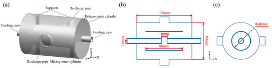
Figure 1.
Schematic diagrams of the CFPCD: (a) stereogram view, (b) center cross section, and (c) center longitudinal section.
3. Numerical Simulations
3.1. Governing Equations
In this paper, liquid single-phase flow was considered, and the working medium was set as the water phase, which was considered to be incompressible and unstable. The continuity equation is given as follows
where vx, vy, and vz are the component of velocity (v) in x, y, and z directions, respectively. The momentum equation is given as follows
where, ρ is the density of fluid medium, t is the time, P is the pressure on the fluid micro element, τ is viscous stress tensor, g is the acceleration due to gravity, F is other external body forces on the micro element.
3.2. Numerical Methods
The 3D model was constructed using UG NX 10.0 software based on the structure shown in Figure 1. Subsequently, the above model was meshed using the ANSYS ICEM 17.0 software, and the hexahedral structured grid was generated. The volume-averaged turbulent dissipation rate (εV) was considered as the characteristic parameter to carry out the grid independence verification. The results of grid independence verification are shown in Figure 2. As observed, the value of εV increased with an increase in the number of grids until the number of grids reached 834072, after which it tended to be stable. By considering both the calculation accuracy and cost, meshing strategy with 834,072 grids was selected for the present study.
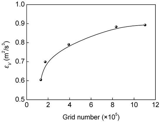
Figure 2.
Grid independence verification.
ANSYS Fluent 17.0 software was used for numerical calculation of the meshed model. The effect of gravity was considered. The inlet and outlet boundary condition were set as the velocity inlet and pressure outlet, respectively. The inlet velocity was set to 1.0, 1.5, 2.0, and 2.5 m/s, respectively. In addition, the inlet initial gauge pressure was set to 0 Pa, the turbulent intensity was set to 5% and the turbulent viscosity ratio was set to 10. The outlet pressure was the relative static pressure, and the corresponding value was 0. Besides, the solid wall was set to no-slip wall. The Eulerian-Eulerian approach was applied to calculate the liquid single-phase flow, and the standard k-ε model was used for turbulence modeling. In solution settings, the pressure-velocity coupling scheme was set as SIMPLE. The gradient was set as Least-Squares-Cell-Based, and the pressure, momentum, turbulent kinetic energy, and turbulent dissipation rate were solved with a second-order upwind scheme. A steady simulation was carried out, and the residuals were set to 10−4. After the calculation converges, the flow field and turbulent characteristic in the CFPCD were analyzed.
3.3. Numerical Simulation Results
3.3.1. Velocity Analysis
Figure 3 presented the velocity nephograms of the CFPCD at Z = 0 mm and X = 0 mm section. As observed, the liquid exhibited the highest flow velocity in the feeding pipe, and the flow velocity decreased rapidly after being released from the feeding tube. The liquid fed from two feeding tubes collided in the center of the inner cylinder, and then spread around until it moved to the inner wall of the inner cylinder. As shown in velocity nephogram at X = 0 mm section, in the liquid collision region, the liquid had a lower flow velocity, and it even closed to zero in the center position. In the diffusion region, the liquid velocity was larger, and decayed with the direction of diffusion. Limited to the obstruction of the cylinder wall, the liquid transformed into a horizontal flow, which diverged to both sides and generated the velocity gradient at the cylinder wall. In the diffusion process at the cylinder wall, the velocity of horizontal flow gradually decreased due to the resistance of the wall and the fluid itself. As the liquid was discharged from the inner cylinder to the outer cylinder, the liquid got rid of the obstruction of the inner cylinder wall, resulting in a spreading movement. However, the liquid tended to maintain a horizontal flow trend with the inertial effect. Therefore, the liquid moved to the outer cylinder in a trumpet-like diffusion state. Subsequently, the liquid moved to the two side walls of the outer cylinder, and spread to the surrounding, achieving dispersion. In the outer cylinder, the liquid flow velocity was small, which was in a relatively stable flow state. Finally, the liquid was discharged from the discharge pipe. It was worth noting that the diameter of the discharge pipe was designed to be larger, and the liquid was discharged at a lower flow rate, preventing the secondary conditioning of pulp after the interaction. The feeding velocity had little effect on the velocity distributions in the CFPCD, and the velocity distributions in the device with different feeding velocities were similar. However, the liquid flow velocity in the device increased with the feeding velocity increased. It indicated that the increase in the feeding velocity could enhance the flow of the fluid in the CFPCD.
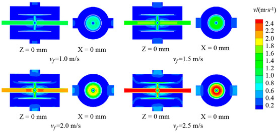
Figure 3.
Velocity nephograms of the CFPCD at Z = 0 mm and X = 0 mm section.
3.3.2. Strain Rate Analysis
Strain rate is the change in strain per unit time, which is an important parameter to reflect strain effect. In the Newtonian fluid, a high strain rate implies a high shear stress and a velocity gradient, which favorably enhances the interaction of particles and reagents. Figure 4 presented the strain rate distributions of the CFPCD at line (Y = 0 mm, Z = 0 mm) and line (X = 0 mm, Z = 0 mm). As shown in Figure 4a, in the feeding pipe, the liquid had a small strain rate, which corresponded to almost zero value. As the liquid moved to the position of about 5 mm from the outlet of the feeding pipe, the strain rate gradually increased, which may be affected by the kinetic energy and momentum transfer of the liquid after the collision. Subsequently, the strain rate of the liquid continued to increase with the flow direction, and reached a maximum value when the two liquids collided. This seemed to imply that the direct collision of two liquids may result in the high shear forces and the velocity gradient. Different from line (Y = 0 mm, Z = 0 mm), the strain rate of line (X = 0 mm, Z = 0 mm) was more complicated due to the diffusion caused by liquid collision and wall bounce. As shown in Figure 4b, the liquid exhibited the highest strain rate distribution in the liquid collision region, which was independent of the feeding velocity. In the liquid collision region, the strain rate increased gradually from the center point (Y = 0 mm) to both sides and reached a maximum value at the point (Y = ± 5 mm), corresponding to the edge of the collision region. Subsequently, the strain rate value decreased abruptly and gradually decreased along the diffusion direction. Approaching the inner wall of the inner cylinder, the obstruction of the wall greatly changed the movement of the liquid, resulting in an increase in the strain rate to a higher value. In the inner cylinder region, the liquid had a higher strain rate distribution, which was favorable for the interaction of the particles and the reagents. However, the strain rate was small in the outer cylinder region, indicating that the flow field was relatively stable, which was conducive to the discharge of pulp. In addition, shear strain increased with increasing feeding velocity in either study range, implying that an increase in the feeding velocity could facilitate particle-collector interactions.
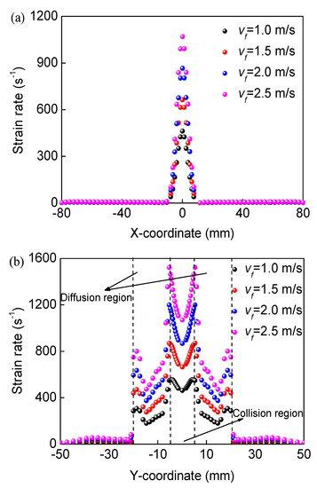
Figure 4.
Strain rate distributions of the CFPCD at various lines: (a) line (Y = 0 mm, Z = 0 mm) and (b) line (X = 0 mm, Z = 0 mm).
3.3.3. Turbulent Kinetic Energy and Dissipation Rate Analysis
Turbulent kinetic energy (k) nephograms of the CFPCD at Z = 0 mm section for different feeding velocities were shown in Figure 5. As observed, after two liquids collided, the turbulent kinetic energy of the fluid increased rapidly. Then, in the diffusion process of fluid, the turbulent kinetic energy gradually increased until it approached the wall. After that, the turbulent kinetic energy gradually decayed with the flow direction. In the mixing inner cylinder, the liquid had a high turbulent kinetic energy distribution, while it was in an opposite state for the outer cylinder. In addition, the feeding velocity had a significant effect on the turbulent kinetic energy inside the CFPCD. The turbulent kinetic energy increased with the increase in the feeding velocity, and the range of high turbulence kinetic energy region also increased. As the feeding velocities were 1.0, 1.5, 2.0, and 2.5 m/s, the corresponding volume-averaged turbulent kinetic energy reached 0.0043, 0.0099, 0.0178, and 0.0281 m2·s−2, respectively.
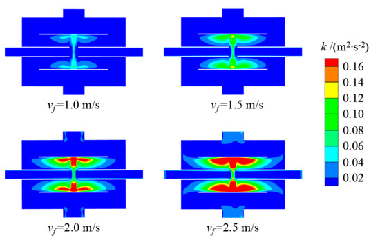
Figure 5.
Turbulent kinetic energy nephograms of CFPCD for different feeding velocities.
Figure 6 presented the turbulent dissipation rate (ε) nephograms of the CFPCD for different feeding velocities. As shown in Figure 6, the turbulent dissipation rate within the CFPCD had a similar distribution to the turbulent kinetic energy, the high turbulent dissipation rate occurred within the mixing inner cylinder. The turbulent dissipation rate increased with an increase in the feeding velocity, and the region with high turbulent dissipation rate also gradually expanded. It is worth noting that for a feeding velocity of 1.0 m/s, the turbulent dissipation rate within the CFPCD was small, without the region of high turbulent dissipation rate. This indicated that the low input energy, namely the low feeding velocity, made it difficult to generate the high turbulent dissipation.
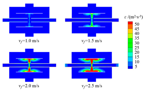
Figure 6.
Turbulent dissipation rate nephograms of the CFPCD for different feeding velocities.
3.3.4. Turbulent Eddy Scale Analysis
The turbulent field can be regarded as composed of turbulent eddies of different scales. Large-scale eddy is missioned to form several small-scale eddies, causing energy transfer. The energy of the small-scale eddy is transferred to smaller eddies, and finally converted into internal energy due to fluid viscous dissipation [25]. The microturbulence, i.e., turbulence of the small eddies in the universal equilibrium range can be described by the Kolmogorov scale (η) [26,27], which is related to the turbulent dissipation rate and fluid viscosity, and can be defined as
where, is the kinematic viscosity.
The Kolmogorov scale distributions of the CFPCD for different feeding velocities were shown in Figure 7. In each studied feeding velocity, the low Kolmogorov scale was mainly distributed in the diffusion region after fluid collision and near the inner wall of the inner cylinder. In the study range, the Kolmogorov scale generated in these regions was less than 25 μm at any feeding velocity. These eddies with a scale comparable to the fine particles were more conducive to promoting the interaction between the fine particles and the collector droplets, which enhanced the pulp conditioning process. This indicated that the CFPCD can produce the good pulp conditioning effect for particles. In the release outer cylinder, the eddy scale was generally large, which was conducive to the transportation and mixing of the pulp. The low Kolmogorov scale distribution range increased with the increasing feeding velocity. As the feeding velocity reached 2.5 m/s, the Kolmogorov scale in the entire mixing inner cylinder was almost below 25 μm, and even reached 15 μm in some regions. Additionally, an increase in the feeding velocity could reduce the average Kolmogorov scale within the CFPCD.
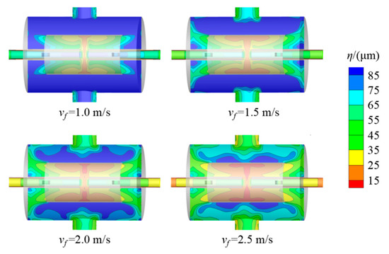
Figure 7.
Kolmogorov scale distributions of the CFPCD for different feeding velocities.
4. Experiments
4.1. Materials
In this study, the coal gasification fine slag samples were collected from Shenhua Ningxia Coal Industry Group in Ningxia, China. To guarantee the sample homogeneity, it was well blended after drying. In proximate analysis, the moisture content, ash content, volatile content, and fixed carbon were measured using 5E-MAG6700 Automatic Proximate Analyzer (KaiYuan, Changsha, China). In ultimate analysis, the content of carbon and hydrogen were measured using CTCH500 Semi-Automatic Hydrocarbon Detector (QiuLng, Changsha, China), the content of elemental nitrogen was measured using K1100 Automatic Kjeldahl Nitrogen Detector (HaiNeng, Shandong China), the content of sulfur was measured using ZCS-8 Intelligent Sulfur Detector (BaoHua, Xuzhou, China), while the content of oxygen was calculated by difference subtraction. The proximate and ultimate analyses of the samples were shown in Table 1. As observed, the moisture content, ash content, and volatile content were 2.30%, 74.52%, and 4.39%, respectively. The content of fixed carbon reached 18.79%, indicating that some of the carbon in the coal gasification fine slag was not fully burned in the gasification process, which was not conducive to the secondary utilization of ash. In the elemental analysis, the carbon content was 94.61%, and the contents of hydrogen, nitrogen, sulfur, and oxygen were 2.29%, 0.60%, 0.75%, and 1.75%, respectively. The residual carbon content occupied the most content in organic matter.

Table 1.
Proximate and ultimate analyses of the coal gasification fine slag.
The mineral composition in the coal gasification fine slag samples was studied using a D8 Advance X-ray diffractometer (Bruker, Bremen, Germany), and the result was shown in Figure 8. As noted, the major crystalline mineral phases in the samples were quartz, gypsum, and mullite. In addition, the characteristic peaks composed of amorphous minerals could be observed in the XRD pattern, which may be unburned carbon [18].
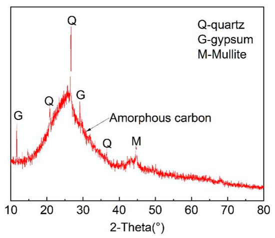
Figure 8.
XRD pattern of coal gasification fine slag.
The coal gasification fine slag contained various constituents, wherein the carbon and ash components were intimately associated. Therefore, dissociation was usually required before the flotation separation. In this study, the dissociation was carried out using a rod mill. In the dissociation process, 240 g of samples were put into a rod mill and ground at 50 Hz frequency for 15 min to disassociate carbon and ash. A BT-9300 Laser Particle Sizer (DanDong Bettersize, Dandong, China) was used to measure the particle size distribution of the sample after grinding and the result was shown in Figure 9. The D10, D50, and D90 were approximately 1.66 μm, 12.95 μm, and 39.76 μm, respectively. Obviously, the content of fine particles in the sample was high, which was the main object of subsequent conditioning-flotation.
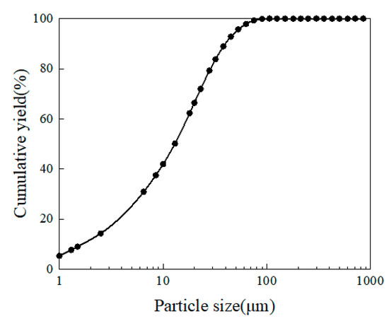
Figure 9.
Particle size distribution of coal gasification fine slag after grinding.
4.2. Methods
The pulp conditioning tests were conducted using a laboratory CFPCD, and the schematic layout of the experimental setup was shown in Figure 10. Coal gasification fine slag samples after grinding and deionized water were added into a mixing tank to prepare pulp with a concentration of 80 g/L. The diesel oil with a dose of 8000 g/t sample and methyl isobutyl methanol with a dose of 8000 g/t sample were subsequently added into the pulp in the mixing tank, respectively. The mixing pulp was fed into the CFPCD using two feeding pumps, and the feeding velocity were adjusted to 1.0, 1.5, 2.0, and 2.5 m/s, respectively. Besides, the conditioning time was constant at 2 min. Finally, the conditioned pulp was collected and prepared for subsequent experiments.
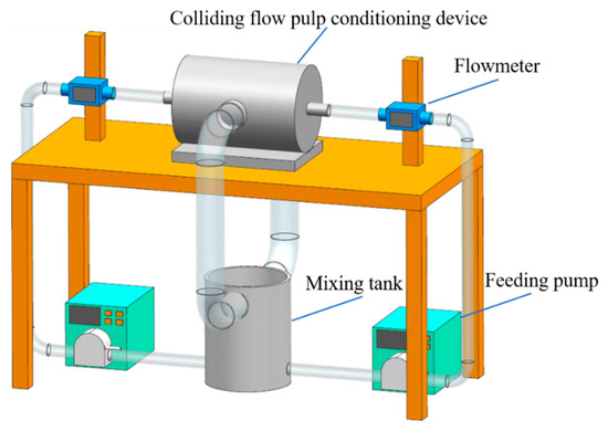
Figure 10.
The schematic layout of the pulp conditioning experimental setup.
The wrap angle measurements were carried out using a home-made attachment process observation system. The prepared coal gasification fine slag samples were added to the observation tank filled with ultrapure water at a concentration of 0.5%. After stirring for 2 min, an air bubble with a diameter of 2.2 mm (±0.1 mm) was generated by a syringe. Subsequently, the pulp was stirred for 60 s using a magnetic stirrer apparatus at a stirring speed of 200 rpm. The attachment process between the sample particles and the air bubble was photographed using an i-SPEED 230 high-speed dynamic camera. After the solution became clear, the wrap angles of the particles were analyzed and obtained. Each experiment was repeated three times at the same position of the observation tank, and the average value was reported as the final data.
In order to avoid the secondary pulp conditioning caused by the stirring of the mechanical flotation machine, all flotation experiments were performed with a home-made inflatable flotation column with a diameter of 50 mm and a height of 600 mm. The collected samples were added to the flotation column, and then air was introduced at a flow rate of 0.15 m3/h. The flotation process lasted for 3 min. The froth products were collected, and the remaining pulp in the flotation column was collected as tailings. The concentrates and tailings were filtered, dried at 80 °C until they reached constant weights, and cooled in a dry atmosphere. The yield (γ), loss on ignition (LOI), and recovery of unburned carbon (RUC) were calculated using Equations (4)–(6).
where wi and wr are the weight of each concentrate and raw sample, respectively (%), A is the ash content, LOIc and LOIr is the LOI of the concentrate and the raw sample.
4.3. Experimental Results and Discussion
4.3.1. Wrap Angle Analysis
Figure 11 presents the wrap angle photos and values of samples for different feeding velocities and wrap angle was shown with red dotted lines. As shown in Figure 11, the wrap angle increased gradually with the increase in feeding velocity, and the particle wrap angle reached 86° when the feeding velocity was 2.5 m/s. It indicated that the particle attachment performance was enhanced with the increase in feeding velocity. This was consistent with the results of flow field simulation. With the increase in feeding velocity, the turbulent dissipation rate increased and the turbulent eddy scale decreased. In the study range, strong turbulence was helpful for achieving the collector dispersion and removing hydrophilic impurities from the particle surface. Meanwhile, the interaction between carbon particles and collector droplets was enhanced, and the attachment effect between them and air bubbles was improved, which was beneficial to the flotation separation of carbon components. In addition, in the study range, the turbulence intensity induced by the device did not reach the degree of excessive conditioning intensity. Therefore, the effect of particle surface modification increased with an increase in feeding velocity.
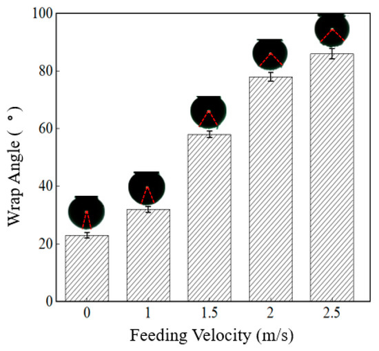
Figure 11.
Wrap angle values of samples for different feeding velocities.
4.3.2. Flotation Results
The flotation results after pulp conditioning for different feeding velocities were shown in Table 2 and Figure 12 (The black arrow represents the black line data being read out on the left axis and the red arrow represents the red line data being read out on the right axis). As observed, the ash content of tailings increased from 82.60% to 90.06% and the RUC increased from 49.57% to 69.83% with the feeding velocity increased from 1.0 m/s to 2.5 m/s. Meanwhile, the LOI of tailings decreased from 17.40% to 9.94%. These results were consistent with the previous flow field simulation and wrap angle analysis. The increase in feeding velocity brought about the increase in velocity gradient and strain rate, and the decrease in turbulent eddy scale, which was beneficial for enhancing the interaction between mineral particles and collector droplets. Therefore, the recovery efficiency of carbon component was improved. This indicated that the colliding flow enhanced the flotation process of coal gasification slag, and the feeding velocity of CFPCD significantly affected the removal performance of unburned carbon. In the study range, the optimum feeding velocity was 2.5 m/s, and the corresponding LOI indicators of flotation tailings products may meet the quality requirements of some mixed mortar and concrete.
Table 2.
Flotation products yield and ash content for different feeding velocities.
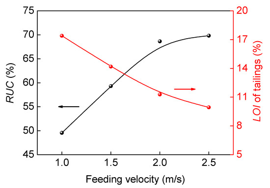
Figure 12.
Flotation results after pulp conditioning for different feeding velocities.
5. Conclusions
The CFPCD was designed to enhance the flotation separation of unburned carbon from coal gasification slag. The flotation intensification mechanism using colliding flow pulp conditioning was investigated by CFD numerical simulation, wrap angle measurements and conditioning-flotation tests. The results showed that the intense colliding flow existed in the inner cylinder colliding flow area of the CFPCD, and the fluid velocity gradient was large, which was conducive to the collision and adhesion between the collector droplets and fine particles. However, in the outer cylinder, the liquid velocity was relatively small and in a relatively stable flow state, which was conducive to the transportation and discharge of pulp. The liquid exhibited the highest strain rate distribution in the liquid collision region, and it reached a maximum value at the edge of the collision region. Subsequently, the strain rate value decreased along the diffusion direction until it reached the inner wall of the inner cylinder, and increased. The turbulent kinetic energy and dissipation rate within the CFPCD had a similar distribution, the high turbulent kinetic energy and dissipation rate occurred within the mixing inner cylinder. The turbulent eddy scale was in the opposite distribution. The feeding velocity had a significant effect on the flow field characteristics in the CFPCD. As the feeding velocity increased, the flow velocity, strain rate, turbulent kinetic energy and dissipation rate increased, together with the decreased turbulent eddy scale. Furthermore, in the study range, the Kolmogorov scale generated in the partial mixing regions was less than 25 μm at any feeding velocity, which indicated that CFPCD produced a flow field environment suitable for pulp conditioning. The wrap angle and conditioning-flotation results illustrated that preconditioning using CFPCD could enhance particle attachment performance and flotation efficiency. The optimum feeding velocity was 2.5 m/s, and the corresponding value of wrap angle, RUC, and LOI of the tailings were 86°, 69.83%, and 9.94%, respectively. These results demonstrated the potential industrial application of the CFPCD on the flotation separation of unburned carbon from coal gasification slag.
Author Contributions
Conceptualization, R.C., H.W., and H.Z.; Methodology, H.W., L.L., and H.Z.; Validation, R.C., D.L., Q.T., and W.S.; Investigation, R.C., Y.L., and Q.T.; Data Curation, R.C., H.W., and D.L.; Writing-Original Draft Preparation, R.C. and H.W.; Writing-Review & Editing, L.L. and H.Z.; Visualization, L.L. and H.Z. All authors have read and agreed to the published version of the manuscript.
Funding
This research was funded by the National Natural Science Foundation of China (Grant No. U21A20325), National Key Research and Development Project of China (Grant No. 2019YFC1904301), the Joint Fund of the Yulin University and the Dalian National Laboratory for Clean Energy (Grant No. YLU-DNL Fund 2021005), the special fund for S&T Innovation Team of Shanxi Province (Grant No.202204051001012) and the Fund of the Assistance Program for Future Outstanding Talents of China University of Mining and Technology (Grant No. 2022WLJCRCZL079).
Data Availability Statement
Data will be made available on request.
Conflicts of Interest
The authors declare no conflict of interest.
References
- Xue, Z.; Dong, L.; Fan, M.; Yang, H.; Liu, A.; Li, Z.; Bao, W.; Wang, J.; Fan, P. Enhanced flotation mechanism of coal gasification fine slag with composite collectors. Colloids Surf. A Physicochem. Eng. Asp. 2022, 641, 128593. [Google Scholar] [CrossRef]
- Yu, W.; Zhang, H.; Wang, X.; Rahman, Z.U.; Shi, Z.; Bai, Y.; Wang, G.; Chen, Y.; Wang, J.; Liu, L. Enrichment of residual carbon from coal gasification fine slag by spiral separator. J. Environ. Manag. 2022, 315, 115149. [Google Scholar] [CrossRef]
- Yuan, N.; Zhao, A.; Hu, Z.; Tan, K.; Zhang, J. Preparation and application of porous materials from coal gasification slag for wastewater treatment: A review. Chemosphere 2021, 287, 132227. [Google Scholar] [CrossRef] [PubMed]
- Liu, X.; Jin, Z.; Jing, Y.; Fan, P.; Qi, Z.; Bao, W.; Wang, J.; Yan, X.; Lv, P.; Dong, L. Review of the characteristics and graded utilisation of coal gasification slag. Chin. J. Chem. Eng. 2021, 35, 92–106. [Google Scholar] [CrossRef]
- Blaisi, N.I.; Roessler, J.G.; Watts, B.E.; Paris, J.; Ferraro, C.C.; Townsend, T.G. Construction material properties of high temperature arc gasification slag as a portland cement replacement. J. Clean. Prod. 2018, 196, 1266–1272. [Google Scholar] [CrossRef]
- Guo, F.; Miao, Z.; Guo, Z.; Li, J.; Zhang, Y.; Wu, J. Properties of flotation residual carbon from gasification fine slag. Fuel 2020, 267, 117043. [Google Scholar] [CrossRef]
- Guo, F.; Guo, Y.; Qiu, G.; Xu, J.; Niu, Y.; Zhang, Y.; Jiang, L.; Hu, X.; Wu, J.; Zhang, H. A new separation flowsheet for resources recovery from waste coal gasification fine slag black water and its benefits analysis. Process. Saf. Environ. Prot. 2022, 164, 836–845. [Google Scholar] [CrossRef]
- Zhang, Y.; Zhu, H.; Zhu, J.; Shi, Q.; Yin, J.; Xu, D.; Valdivieso, A.L. Characteristic evolution and energy variation during the generation of kerosene droplet. Fuel 2020, 288, 119684. [Google Scholar] [CrossRef]
- Zhu, X.; Wei, H.; Hou, M.; Wang, Q.; You, X.; Li, L. Thermodynamic behavior and flotation kinetics of an ionic liquid microemulsion collector for coal flotation. Fuel 2019, 262, 116627. [Google Scholar] [CrossRef]
- Shen, L.; Min, F.; Liu, L.; Zhu, J.; Xue, C.; Cai, C.; Zhou, W.; Wang, C. Application of gaseous pyrolysis products of the waste cooking oil as coal flotation collector. Fuel 2018, 239, 446–451. [Google Scholar] [CrossRef]
- Wang, H.; Liang, Y.; Li, D.; Chen, R.; Yan, X.; Zhang, H. Collisional interaction process between a bubble and particles with different hydrophobicity. Sep. Purif. Technol. 2022, 301, 121940. [Google Scholar] [CrossRef]
- Wang, Y.; Zhou, Y.; He, Q.; Xing, Y.; Bao, X.; Gui, X.; Wang, L. Research on Mechanisms of Improving Flotation Selectivity of Coal Slime by Adding Sodium Polyphosphate. Minerals 2022, 12, 1392. [Google Scholar] [CrossRef]
- Yang, R.; Shen, L.; Wang, H. Research on emulsified tyre pyrolysis oil as a coal flotation collector. Physicochem. Probl. Miner. Process. 2017, 53, 279–287. [Google Scholar]
- Wang, H.; Yang, W.; Li, D.; Zhang, C.; Yan, X.; Wang, L.; Zhang, H. Enhancement of coal flotation using impact flow conditioning pulp. J. Clean. Prod. 2020, 267, 122124. [Google Scholar] [CrossRef]
- Li, D.; Zhang, C.; Li, X.; Yang, L.; Yan, X.; Wang, L.; Liu, Q.; Zhang, H. Experimental study on the preconditioning of fine coal particles surface modification using a new type flow mixer. Fuel 2020, 268, 117361. [Google Scholar] [CrossRef]
- Fan, G.; Zhang, M.; Peng, W.; Zhou, G.; Deng, L.; Chang, L.; Cao, Y.; Li, P. Clean products from coal gasification waste by flotation using waste engine oil as collector: Synergetic cleaner disposal of wastes. J. Clean. Prod. 2020, 286, 124943. [Google Scholar] [CrossRef]
- Shi, D.; Zhang, J.; Hou, X.; Li, S.; Li, H.; He, F. Adsorption mechanism of a new combined collector (PS-1) on unburned carbon in gasification slag. Sci. Total. Environ. 2021, 818, 151856. [Google Scholar] [CrossRef]
- Zhang, R.; Guo, F.; Xia, Y.; Tan, J.; Xing, Y.; Gui, X. Recovering unburned carbon from gasification fly ash using saline water. Waste Manag. 2019, 98, 29–36. [Google Scholar] [CrossRef]
- Evans, G.M.; Doroodchi, E.; Lane, G.L.; Koh, P.T.L.; Schwarz, M.P. Mixing and gas dispersion in mineral flotation cells. Chem. Eng. Res. Des. 2008, 86, 1350–1362. [Google Scholar] [CrossRef]
- Engel, M.; Middlebrook, P.; Jameson, G. Advances in the study of high intensity conditioning as a means of improving mineral flotation performance. Miner. Eng. 1997, 10, 55–68. [Google Scholar] [CrossRef]
- Yang, L.; Li, D.; Zhu, Z.; Xu, M.; Yan, X.; Zhang, H. Effect of the intensification of preconditioning on the separation of unburned carbon from coal fly ash. Fuel 2019, 242, 174–183. [Google Scholar] [CrossRef]
- Feng, B.; Lu, Y.-p.; Feng, Q.-m.; Ding, P.; Luo, N. Mechanisms of surface charge development of serpentine mineral. Trans. Nonferrous Met. Soc. China 2013, 23, 1123–1128. [Google Scholar] [CrossRef]
- Yu, Y.; Cheng, G.; Ma, L.; Huang, G.; Wu, L.; Xu, H. Effect of agitation on the interaction of coal and kaolinite in flotation. Powder Technol. 2017, 313, 122–128. [Google Scholar] [CrossRef]
- Wang, W.; Liu, D.; Tu, Y.; Jin, L.; Wang, H. Enrichment of residual carbon in entrained-flow gasification coal fine slag by ultrasonic flotation. Fuel 2020, 278, 118195. [Google Scholar] [CrossRef]
- Nguyen, A.V.; An-Vo, D.-A.; Tran-Cong, T.; Evans, G.M. A review of stochastic description of the turbulence effect on bubble-particle interactions in flotation. Int. J. Miner. Process. 2016, 156, 75–86. [Google Scholar] [CrossRef]
- Yang, L.; Zhu, Z.; Qi, X.; Yan, X.; Zhang, H. The Process of the Intensification of Coal Fly Ash Flotation Using a Stirred Tank. Minerals 2018, 8, 597. [Google Scholar] [CrossRef]
- Zheng, K.; Yan, X.; Wang, L.; Zhang, H.; Cao, Y.; Guo, C. Turbulent effects of vortex generators on the separation of fine particles. Chem. Eng. J. 2021, 418, 129373. [Google Scholar] [CrossRef]


Disclaimer/Publisher’s Note: The statements, opinions and data contained in all publications are solely those of the individual author(s) and contributor(s) and not of MDPI and/or the editor(s). MDPI and/or the editor(s) disclaim responsibility for any injury to people or property resulting from any ideas, methods, instructions or products referred to in the content. |
© 2023 by the authors. Licensee MDPI, Basel, Switzerland. This article is an open access article distributed under the terms and conditions of the Creative Commons Attribution (CC BY) license (https://creativecommons.org/licenses/by/4.0/).