Article

Re-Mining of Waste Rock Dumps from a Closed Lead–Zinc Mine—Characterisation of the Residuals

1
Chair of Mineral Processing, Department Mineral Resources Engineering, Montanuniversität Leoben, Franz Josef Strasse 18, 8700 Leoben, Austria
2
Chair of Geology and Economic Geology, Department Applied Geosciences and Geophysics, Montanuniversität Leoben, Franz Josef Strasse 18, 8700 Leoben, Austria
3
GKB-Bergbau GmbH, Voitsberger Strasse 17, 8572 Bärnbach, Austria
*
Author to whom correspondence should be addressed.
Minerals 2023, 13(3), 361; https://doi.org/10.3390/min13030361
Submission received: 14 February 2023 / Revised: 28 February 2023 / Accepted: 2 March 2023 / Published: 4 March 2023

Abstract

:
The lead–zinc mine Bleiberg-Kreuth located in the Austrian federal state of Carinthia has had a long mining history, spanning from the early 14th century to the 1990s. The mining and processing activities undertaken over the centuries and, consequently, the composition of the waste rock material changed throughout this period. Today, the focus on waste rock dumps is motivated firstly by environmental interests and secondly by economic aspects. This article provides a comprehensive approach for the characterisation of three different waste rock dumps. The characterisation covers both mineralogical–geological methods and those involving the use of a mineral processor. The characterisation method presented herein starts with the sampling and calculation of the sampling mass, followed by sieve analysis and sink–float analysis, resulting in a two-dimensional fractional analysis. The consolidated results of the fractional and chemical analyses allow for a simplified forecast model for an ideal classification and density separation. Finally, the practical processability of a pre-concentration was tested by trials for comminution, classification, and density sorting.

1. Introduction

The Pb–Zn deposit Bleiberg-Kreuth is located in the Drau Range of the Eastern Alps about 50 km west of Klagenfurt, Austria. It is the “Alpine type Pb–Zn mineralisation” (APT) type of locality, which was first described by the authors of [1,2,3] and cited in [4]. The deposit is hosted by thick Triassic carbonate sequences with five different mineralised horizons. The majority of the lead and zinc ore occurs in the “Erzkalk” or Bleiberger facies, which contain over 1000 km of underground drives and gateways [5]. The primary type of mineralisation consists mostly of galena [PbS], sphalerite [ZnS], marcasite and pyrite [both FeS2], and the gangue minerals calcite [CaCO3], dolomite [CaMg(CO3)2], fluorite [CaF2], baryte [BaSO4], and anhydrite [CaSO4]. The oxidation zone is dominated by cerussite [PbCO3], anglesite [PbSO4], hydrozincite [Zn5[(OH)2/CO3]2], hemimorphite [Zn4[(OH)2/Si2O7]∙H2O], smithsonite [ZnCO3], wulfenite [PbMoO4], goethite [α-FeO(OH)], lepidocrocite [γ-FeO(OH)], and calcite [6]. Sphalerite has low Fe content (median 0.5%) and has average fractions of 174 ppm of Ge and 1910 ppm of Cd [7], besides locally elevated As, Tl, and Pb. Galena is Ag-poor but contains As (0.2%) and Sb (0.05%), [8]. Unless otherwise specified, all relative quantities in this article, such as percentages or ppm, are mass-related.
Mining in the Bleiberg Valley likely started in the 13th century but was first documented in 1333. After more than 500 years, the Bleiberger Bergwerks Union (BBU) was founded in 1867. The BBU ran the mine, partly with limited operation services, until its closure in 1993 [9]. In total, 1.1 million tons each of lead and zinc, 993 tons of cadmium, 172 tons of germanium, and 500 tons of molybdenum were extracted [10]. The production data indicate that the Pb/Zn ratios increased from west to east, as well as the Mo concentrations present as wulfenite. Therefore, mining started in the east to recover Pb, and only later moved to the west to recover Zn. Wulfenite was mainly concentrated in the mines “Stefanie”, “Franz-Josef”, and “Sonnseite” [11]; the dumps investigated in this study are all located at the immediate east of the Stefanie mine.
GKB-Bergbau GmbH is responsible for overseeing several mine permissions in Austria, among which number the inactive mines at Bleiberg. The volume of waste rock material deposited by mining and processing in the Bleiberg Valley is estimated at about 3 million cubic metres. GKB is a partner company in the COMET project COMMBY (Competence network for the assessment of metal bearing by-product) that supported the research activities described in this article.

2. Motivation

Many residues from various processes and stages of technological progress have accumulated over the centuries and been stored in landfills, tailings ponds, dumps, and waste dumps. Compared to today’s raw material deposits, several of these landfills contain high metal levels. In addition, the landfills are usually easily accessible, and the quantities are already known or can be accurately estimated. In any case, the potential for reprocessing these residual materials is high. From a mining and process-engineering perspective, these residual materials offer the advantage of already being in a crushed state. This saves process infrastructure and thus energy and costs for future processes [12].
Following the closure of the mine in Bleiberg-Kreuth, attention has shifted to all operations involving the safety of local residents and the environment. Repair and maintenance work has been, and will continue to be, a priority. The maintenance of mine workings, ventilation, and water drainage systems are among such tasks. Mineralogy, geology, and mining history research continued after the mine’s closure. Work on the genesis and age of the deposit is particularly noteworthy [10]. Several variables have altered in recent years, including the economic environment, global strategic reassessment, and the drive towards more sustainable resources. This has also motivated GKB Bergbau GmbH to give waste rock dump sampling and potential reprocessing some initial consideration.
In the former mining district of Bleiberg-Kreuth, three waste rock dumps were selected according to previous investigations of production data and documentation carried out by the partner company GKB Bergbau GmbH. The mining area is located in a steep alpine terrain; thus, in addition to the size of the dumps, accessibility by road was also a selection criterion. The samples are an undefined mixture of mainly “processing residues” and “excavated material” from the drift excavation of the historical lead–zinc mine in Bad Bleiberg [12]. The processing residues are coarser grains from different mining eras, which have been sorted out, e.g., via density separation or hand sorting. Fine-grained residues from flotation are not included in these waste rock dumps. Besides the original valuable elements lead and zinc, molybdenum is also of interest today.

3. Material and Methods

3.1. Mineralogy

Bleiberg-Kreuth is a carbonate-hosted Pb–Zn ore deposit in which the metal-bearing minerals are associated with calcite and dolomite as well as with other gangue minerals such as quartz, fluorite, and baryte. The most important Pb-, Zn-, and Mo-bearing minerals of the Bleiberg dumps are of a secondary origin due to oxidation processes that have occurred over the past centuries. These secondary minerals include cerussite, anglesite, smithsonite, hemimorphite, wulfenite, and limonite [FeO(OH)∙nH2O], [13]. Thus, the amount of the primary sulphides, galena, sphalerite, and pyrite is low.
Cerussite, wulfenite, and limonite are often found to replace galena that is still present as relict grains, whereas sphalerite is usually missing. The fine-grained limonitic material (with a grain size usually −30 µm) contains up to 30% lead and/or zinc. Wulfenite and anglesite form grains of up to 500 µm in size. Inclusions of descloizite (−125 µm; [PbZn(VO4)(OH)]) were found within cerussite. Particle sizes of the secondary minerals cerussite and smithsonite are typically up to 2 mm.
In general, the secondary mineral phases show a rather complex intergrowth with the carbonate host rock or gangue minerals. However, the particle boundaries are very clear. At a particle size of −300 µm, the metal-bearing minerals are liberated from the surrounding material.

3.2. Waste Rock Dumps—Past and Present Investigations

For a long time, the major focus at Bleiberg was on galena for extracting lead and calamine for extracting zinc; sphalerite was also mined, but not processed, and was dumped with the waste rock. Smelting and processing methods improved, and demand for zinc metal increased steadily. As a result, previously worthless sphalerite-containing dumps came into focus. The waste dumps of the Bleiberg-Kreuth mine were first inventoried in 1938. Processing of the dumps started in 1941, and only the older, richer dumps from the western mines were processed until 1956. Dump ore accounted for approximately 20% of overall beneficiation in 1941. The average grade was 0.69% lead in total—oxidic and sulphuric—and 4.49% sulphuric zinc; only the sulphuric portion could be concentrated. The metal content distribution between raw ore and dump ore was 96:4% for lead and 76:24% for zinc. Ongoing additions and further investigations towards lead and zinc extraction carried out by E. Schroll in 1951/52 formed the framework for all production planning [14]. Dump ore reserves were estimated to constitute around 859,000 t in 1982, with the major dumps of the “Rudolf” and “Antoni” mines in the middle to western area of the Bleiberg valley. In 1982, the amount of dump ore used for overall beneficiation was substantially greater than in 1941, at roughly 55%. The average composition was 0.41% lead and 1.97% zinc. The metal content distribution between raw ore and dump ore was 67:33% for lead and 60:40% for zinc [15].
Investigations by E. Schroll conducted in 1951–1952 on the molybdenum content of waste dumps in the eastern part of the mining area yielded grades between 0.1%–0.3% Mo. In the years 1946–1952, the economic conditions permitted the extraction of wulfenite from waste dumps. A total of 775 t of molybdenum concentrates with a grade of 11.9% were recovered from about 60,000 t of waste dump ore. The plant was shut down in 1960 [16].
Scherer [14] reported average grades of 0.52% lead and 0.21% zinc in about 360,000 t of waste dumps from the “Sonnseite” area in the eastern section of Bleiberg (Figure 1). At the time, these dumps could not be considered valuable reserves due to their high oxidic concentrations of up to 0.5% lead or zinc oxides [15].
Large dumps in the western area of Bleiberg were mostly processed in the 1980s according to current data. Now that these settlement regions have been populated, many residual dumps are unavailable. The dumps to the east are mostly accessible. Research carried out by GKB estimated that about 21 dumps may be reached and examined. Among these, three dumps located in the eastern part of the mining area, marked in Figure 1, were investigated in this work. Two of these dumps are situated in the “Sonnseite” region; they are named “Matthäus” (H) and “Glück” (K). The bigger dump, “Altstefanie” (A), is part of the “Stefanie” region.

3.3. Sampling

One of the most frequently underestimated tasks in an assessment project is the sampling strategy. Regardless of the purpose of sampling, sufficient planning must precede a sampling survey to ensure that fundamental sampling errors are minimised. Nevertheless, the designing engineer must weigh the effort of a sampling survey against the expected value of the information.
GKB Bergbau GmbH began planning for this sample survey years ago. This job mostly consisted of reviewing old production data, site documentation, and on-site inspections. It offered an early summary of the availability and quantity of the various waste rock dumps.
In this project, the sampling process for each waste rock dump was split into two stages. The first stage was pre-sampling, which entailed less effort with respect to the sampling of the waste rock dumps. The execution of the pre-sampling labour took around two days for two people without special machinery. The results of the corresponding calculations form the basis for the second stage, i.e., the actual sampling survey. One of the dumps has large dimensions (Altstefanie, A) and was, therefore, sampled at two places: at the base of the dump and at the top. Consequently, four samples were obtained: two were taken from the Altstefanie waste rock dump and one each was taken from the Matthäus and Glück dumps. The four samples were screened on-site at 40 mm. The survey thus yielded eight samples from three dumps (see Table 1) to work with. The second sampling stage required around four days of labour for five employees. Furthermore, two specialists were required to operate the excavators, particularly the walking excavator, as well as the transfer truck.

3.3.1. Stage One: Pre-Sampling

The goal of pre-sampling is to obtain an initial impression of a substrate’s chemical composition and to estimate sample mass with additional statistical information for the second stage. For this purpose, incremental samples were taken from the dumps at various sampling points using a shovel. These were combined into a collective sample of about 100 kg. The particle size distribution resulting from the sieve analysis formed the basis of further calculations, which are explained in Section 5. Chemical analysis was performed on selected particle size fractions from sieve analysis; the results are shown in Section 6.1.

3.3.2. Stage Two: Sampling

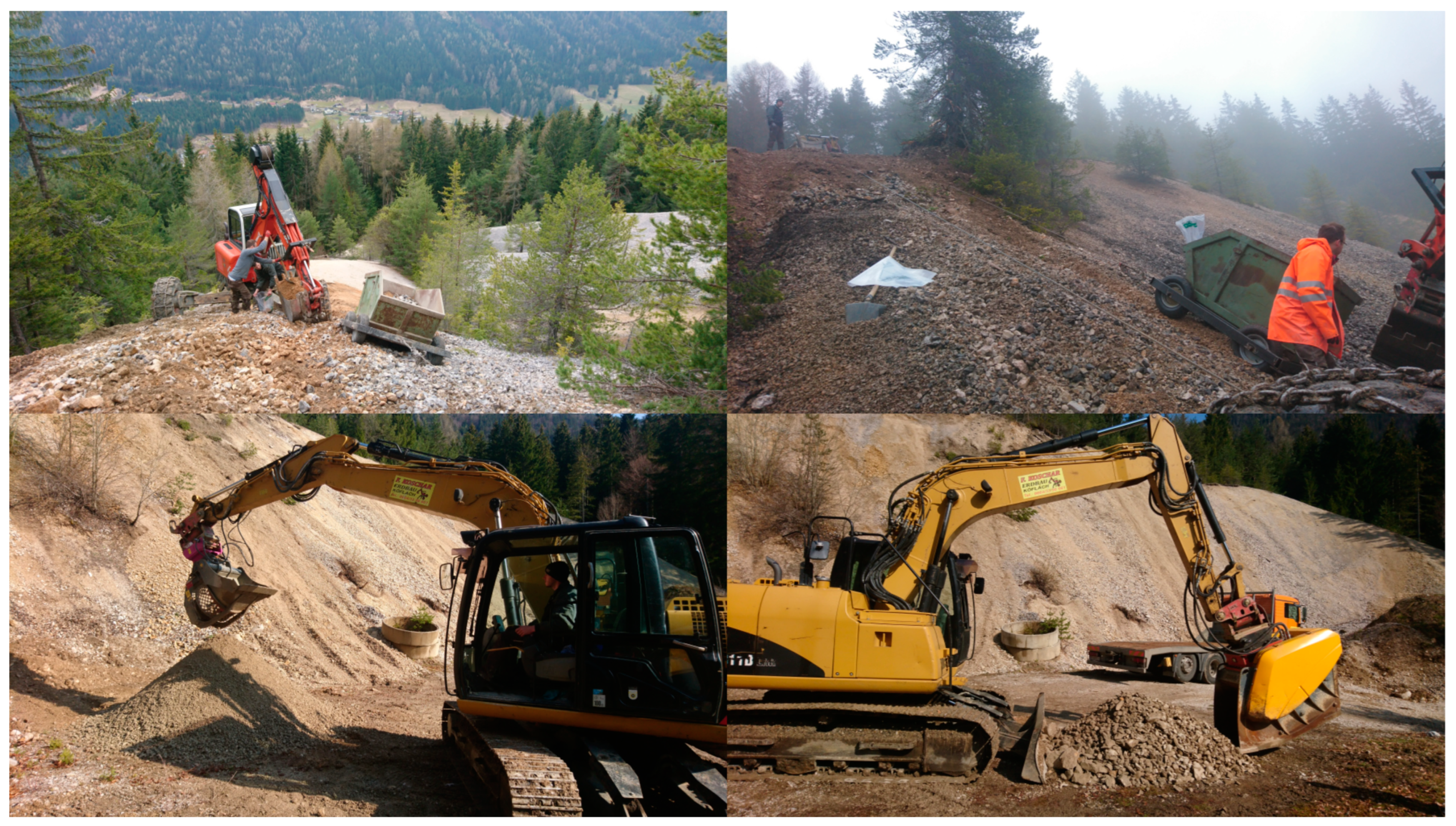
As in the first stage, incremental samples were collected at various sampling points and then combined into a collective sample. The steep and exposed positions of the dumps required the use of a walking excavator equipped with a winch and a backhoe with a volume of approx. 0.17 m3. Figure 2 graphically illustrates the sampling process and Figure 3 shows some photographs of the sampling conducted on-site. The incremental samples were transported to a collection point with a custom-made sample trolley, which was also equipped with a winch. At the collection point, the sample was screened at a mesh size of 40 mm. The oversize fraction was then crushed with a jaw crusher. Both fractions, the prior oversized fraction and the undersized one, were separately homogenised and piled into small, longitudinal heaps. From these heaps, 30 incremental samples were taken at random with a shovel; consequently, these formed the laboratory sample units with a mass of about 150 kg each.

3.4. Laboratory Studies and Equipment

Sieve analysis in this work was performed manually with wire mesh test sieves according to the German standard (ISO 3310-1:2017) [18]. The scales used were in accordance with the mass to be weighed, resulting in the corresponding readabilities (readability/weighing capacity: 0.0001 g/220 g, 0.01 g/1510 g, and 0.5 g/35 kg). The sample density was determined using a gas pycnometer from the manufacturer Micromeritics GmbH (Model AccuPyc II 1340, Norcross, GA, USA). The used centrifuge was from the manufacturer Beckman Coulter Inc. (Model Allegra X-30R, Brea, CA, USA).

3.4.1. Sample Material

As described above, the sample material is a residue from historical mining and processing activities. The investigations described in this study were performed on all waste rock dumps (A1 top, A1 base, H, and K). For the sample “A1 top,” a more complete summary is provided. The first part covers the fractional analysis of a fraction of −1 mm of the uncrushed samples present at the waste rock dumps. The second part also concerned the coarser fractions of +1 mm, which were pre-concentrated using gravitational methods.

3.4.2. Fractional Analysis—Sink–Float Analysis

The purpose of fractional analysis is to classify the contained minerals according to the physical properties of interest; in this case, the focus is on the size and density of the particles, thus necessitating a two-dimensional fractional analysis. The first dimension is the particle size, which was assessed by sieve analysis, and the second dimension is the density, which was determined by the sink–float analysis, also known as laboratory heavy liquid test. As described in [19], the results will finally help evaluate the mineral and metal distribution and assess the samples’ suitability for gravity separation. Figure 4 illustrates the steps of the analysis.
The sink–float analysis was carried out with sodium polytungstate (SPT). SPT is soluble in water, can be easily regenerated, and is non-toxic (and, therefore, easy to handle). A disadvantage of SPT solution is its rather high viscosity (e.g., 37 mPa·s at 3 g/cm3), which hampers fractionation as the particle size decreases. The analysis of particles smaller than 315 µm was thus supported via a centrifuge. Another disadvantage of SPT is its reactivity with some ions in solution, which can lead to insoluble precipitates. SPT has a pH of about 3 at a density of 3 g/cm3. Some minerals may react under this higher acidity, such as carbonates. Hence, the pH value was raised to 7 during this investigation. [20]

4. Laboratory Sorting Trials—Pre-Concentration

The goal was to assess the complete sample, the fraction of −1 mm, and the fraction of +1 mm using a pre-concentration trial comprising the following stages: comminution, classification, sorting, and sorting product analysis. Comminution to 100% −1 mm was followed by classification and a multi-stage gravity-sorting process. A laboratory jaw crusher (BB 200, Retsch, Haan, Germany), a laboratory rod mill (rod charge 7.5 kg, DxL 150 mm × 300 mm, Alpine, Augsburg, Germany), and a pilot-scale vertical roller mill (VRM 200, Cemtec, Enns, Austria) were utilised for comminution. Screening was performed either manually or with a vibrating screen (VRS 800, Allgaier, Uhingen, Germany) and classification was performed with a laboratory hydraulic classifier (self-construction, Chair of Mineral Processing, Leoben, Austria). Testing for gravity concentration was completed using a gravity spiral concentrator (Five turns, Krebs FLSmidth, AZ, USA) and a shaking table (K 1794 250 mm × 500 mm, Krupp, Magdeburg, Germany).

4.1. Screening, Comminution, and Classification

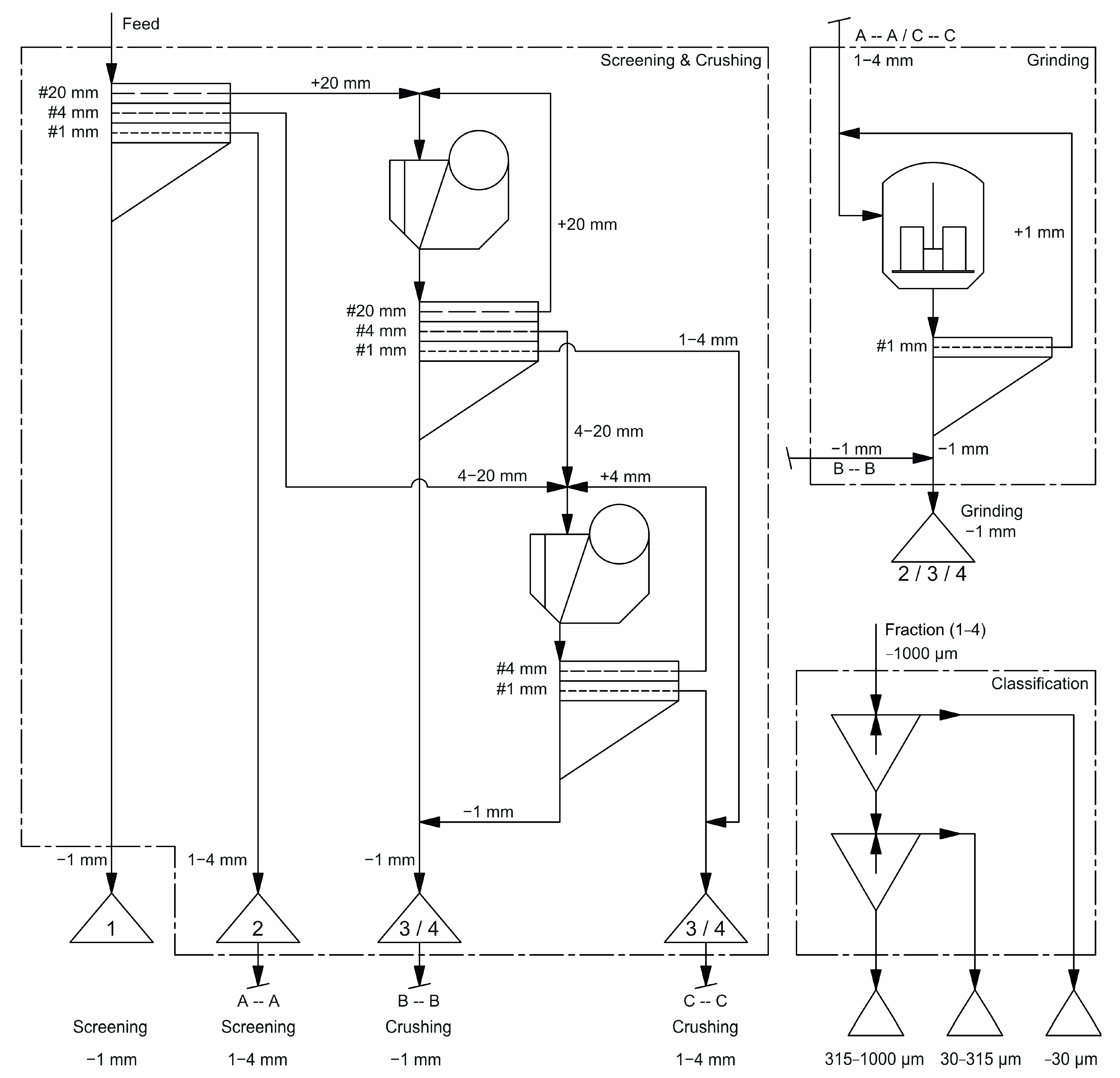
Pre-screening at 20, 4, and 1 mm mesh sizes was carried out, followed by two-stage size reduction in a closed circuit down to 100% finer than 4 mm, as illustrated in Figure 5. The closed size settings (CSS) of the jaw crusher were 20 mm in the first stage and 4 mm in the second stage. All fractions of 1–4 mm were ground to −1 mm by means of a vertical roller mill. The comminution circuit yields four fractions with a grain size of −1 mm, allowing for the determination of the elemental content of the original grain size fractions of the waste rock dumps, which are listed in Table 2. To prepare for gravity concentration, each fraction was deslimed at 30 µm and classified at 315 µm using a laboratory hydraulic classifier, resulting in three size classes: 315–1000 µm, 30–315 µm, and −30 µm.

4.2. Gravity Concentration Trials

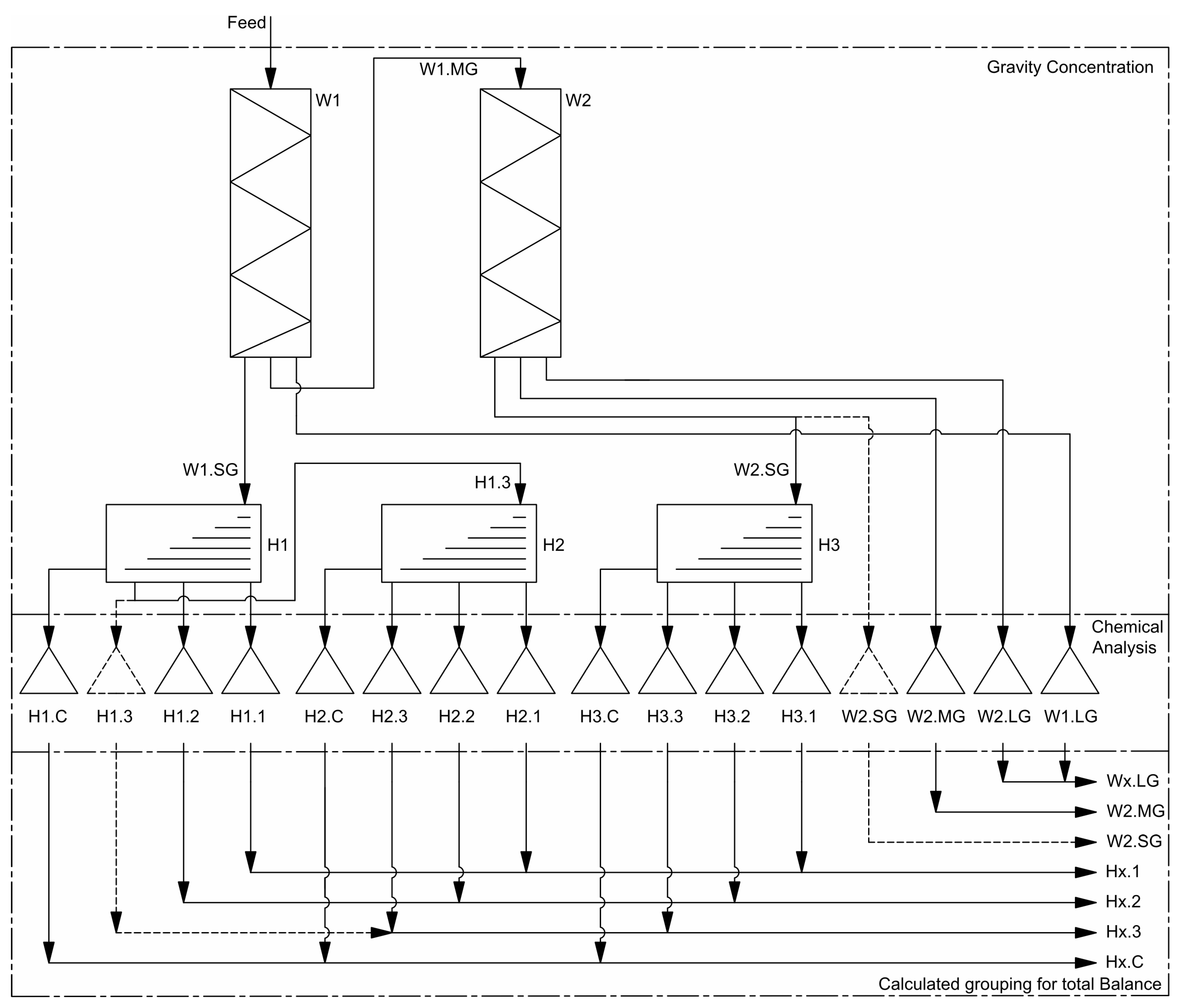
The feed material used for the gravity concentration experiments consisted of the two coarser classifier fractions of 315–1000 µm and 30–315 µm taken from all the samples (see Table 2), namely, a total of eight samples. A few test runs provided the settings shown in Table 3. Figure 6 shows the flowchart of the gravity concentration trials. The spirals served as roughing agents, and the shaking tables served as cleaners. Five fractions were obtained from the two-staged spiral concentration: The heavies of the first spiral stage (W1.SG) formed the feed for the shaking table (H1). The middlings of the first spiral stage (W1.MG) were fed to the second spiral stage (W2), wherein the heavies (W2.SG) were also fed to a shaking table (H3). The lights of the first (W1.LG) and second stages (W2.LG) were not processed further. Each shaking table step produced four fractions: concentrates (Hx.C), middlings (Hx.3), and two tailings (Hx.1 and Hx.2). The middlings of the first shaking table stage (H1.3) were re-cleaned during the second shaking table stage (H2). Both the fractions H1.3 and W2.SG were only re-cleaned if there was enough sample mass left for chemical analysis. The trials produced a total of 112 fractions for chemical analysis.

4.3. Methodology of Chemical Analysis

The “pre-sampling” samples were screened into several particle size fractions and analysed by ICP-MS after Na2O2 dissolution was carried out at Montanuniversitaet Leoben. The samples for used XRF analysis were ground to a fine powder using an agate disc vibrating mill. After being dried overnight at 105 °C, the powder was ignited at 1050 °C for 2 h in a muffle furnace to determine the loss on ignition (LOI). The ignited samples were ground again and dried overnight. Totals of 10.0000 g ± 0.0005 g of flux (66.67% lithium-tetraborate, 32.83% lithium-metaborate, 0.50% lithium-iodide) and 1.0000 g ± 0.0005 g of ignited sample were prepared as fused beads in a fully automatic fusion machine (Claisse Eagon 2, Malvern Panalytical, Almelo, Netherlands). Measurements were performed using a wavelength dispersive XRF spectrometer (Axios FAST mAX, Malvern Panalytical, Almelo, Netherlands) at Montanuniversitaet Leoben. The following oxides were analysed: Na2O, MgO, Al2O3, SiO2, P2O5, SO3, K2O, CaO, TiO2, V2O5, Cr2O3, Mn3O4, Fe2O3, NiO, CuO, ZnO, SrO, ZrO2, MoO3, BaO, HfO2, and PbO. To validate these results, selected samples were sent to an accredited laboratory (Actlabs, Ancaster, ON, Canada), fused with sodium peroxide, and analysed by ICP-OES and ICP-MS to search for the following elements: Al, As, Be, Bi, Ca, Co, Cr, Cs, Cu, Fe, Ga, Ge, In, K, Li, Mg, Mn, Mo, Nb, Ni, Pb, Re, S, Sb, Se, Si, Sn, Ta, Te, Th, Ti, Tl, U, W, and Zn.

5. Theory/Calculation

The sampling theory applied in this study is based on [21,22], which, in turn, is based on [23] and [24]. As described similarly in [25], the total variance ( S t o t 2 ) is composed additively of the sum of the partial variances, namely, the composition or random variance ( S C 2 ), the distribution or segregation variance ( S D 2 ), and the preparation and analysis variance ( S P A 2 ). The general term could be expressed as presented in Equation (1).
S t o t 2 = S C 2 + S D 2 + S P A 2
Steiner introduced the relationship between the sample inhomogeneity and the sampling unit mass as a fundamental stochastic error or random variance (Equation (2)). Therefore, as the sample mass increases, the random variance will decrease.
S C 2 = I M s u
I = i = 1 i m a x [ C i · k i 3 · ρ i · m i · ( x i x ¯ ) 2 ]
The sample inhomogeneity ( I , kg%2) is calculated as the sum over all particle size classes. The summands are made up of the volumetric particle shape factor C i (−), the number equivalent particle size k i (m), the material density ρ i (kg/m3), the mass fraction m i (%), the fraction x i (%) of the component of interest (such as an element, oxide, mineral, etc.), and the corresponding mean content of the sample unit x ¯ (%).
To determine a sample’s inhomogeneity, a fractional analysis on suitable properties—as in the example in Section 3.4.2., but also including, at least, a particle size analysis—is required. In this work, inhomogeneity was estimated only through the particle size distribution from the sieve analysis. An example of the results for the sample “A1 top” is shown in Table 1.
For the estimation of the total variance ( S t o t 2 ), some simplifications were made. It was assumed that the collective samples comprise a high number of sample increments ( S D 2 = 0 ) and that an ideal sieving process was carried out ( S P A 2 = 0 ). The calculated total variance thus gives the lowest possible deviation of the analytical result. Consequently, the necessary sample size ( M s u ) can be estimated from the random variance and the calculated inhomogeneity (Equation (2)). For small sample increments (N ≤ 30), the necessary sample size can be calculated via the Student distribution with a defined statistical certainty (usually 95%) for a required deviation.

6. Results and Discussion

6.1. Chemical Analysis of Pre-Sampling

Table 4 presents selected elements of different particle size fractions from the three waste rock dumps. As expected, the content increases as particle size decreases. The lead, zinc, and molybdenum grades are the lowest in “Altstefanie”. “Matthäus” has the greatest lead and molybdenum concentrations in the finest fraction of −0.5mm, with 9.5% and 1.1%, respectively. The zinc grade of the “Glück” dump is high, ranging from 6.8 to 7.8%, as well as that of barium, with 2.9% and 5.9%.
High-value germanium is not found in any sample in significant amounts and is far lower (−8 ppm) than the average value of 174 ppm calculated for zinc concentrates from the Bleiberg mine [7]. The low Ge values are partly due to low sphalerite concentrations within the dump material, and partly to sphalerite oxidation and the removal of Ge during the transformation of sphalerite into calamine minerals. Germanium will either accumulate in iron hydroxides or migrate into groundwater, depending on the pH. According to Schroll [8], Ge remains primarily in hemimorphite, where Ge4+ is thought to substitute for a Si4+. Consequently, a reduced hemimorphite amount can be assumed. The observed cadmium concentrations are also lower than the known average of 1910 ppm in Zn concentrates. “Altstefanie” has the lowest values, between 34–47 ppm, followed by “Matthäus” with 87–168 ppm. “Glück” has the highest concentrations, which are around 240 ppm.

6.2. Particle Size Distribution and Mean Densities

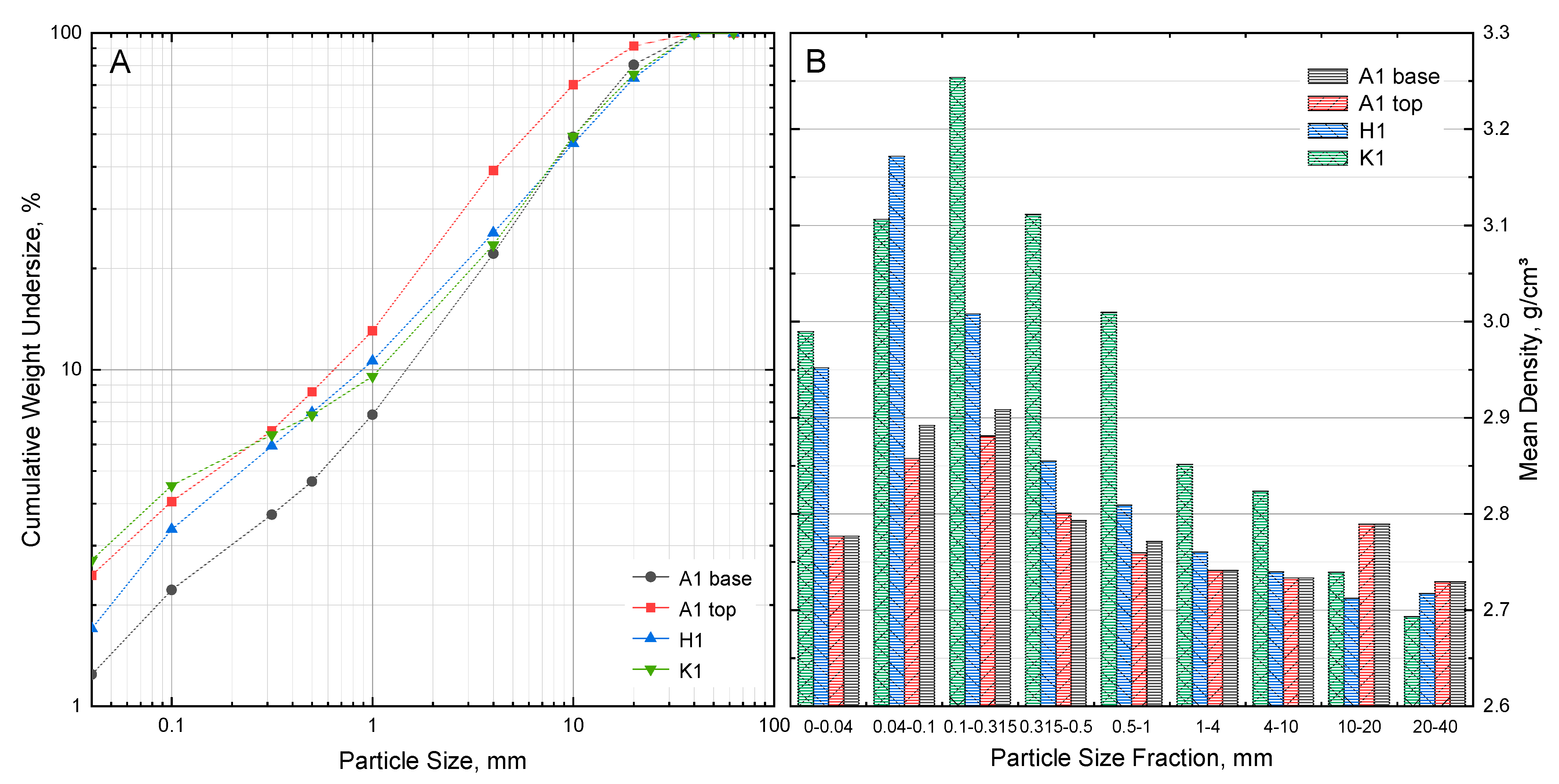
Figure 7A shows the particle size distribution of all four collective samples from sampling stage 2. As expected, the particle size distribution in the area of the dump base (A1 base) is coarser than the rest, which can be explained by segregation effects.
Figure 7B presents the mean densities of the particle size fractions of −40 mm. As shown in this plot, the mean densities increase steadily with a decreasing particle size until they peak either at 100–315 µm or 40–100 µm. This indicates a higher content of heavy minerals in these particle sizes. The subsequent lower density in the fines is caused by the presence of organic matter. The removal of organic matter is quite easy with particles of +100 µm. However, with finer particle fractions, this is also associated with greater effort and losses of mineral grains.
Table 5 shows the results of the sieve analysis of the sample “A1 top”, including the deviations and the inhomogeneity according to the statistical calculations from Section 5. As the particle size rises, the number of particles in a particle size fraction decreases, resulting in greater inhomogeneity. Up to the particle size fraction of 10–20 mm, inhomogeneity is rather low. The next largest particle size fraction, 20–40 mm, has four times the inhomogeneity and hence a greater deviation. The number of particles within a particle size fraction should be sufficient for the given collective sample mass of 100 kg, especially for particles smaller than 10 mm. With a statistical confidence of 95%, the result of the sieve analysis carried out can be reported as follows: the weight of a size fraction, for example, of 0.5–1 mm is 13.04% and the deviation is 0.18%-pts, thus equalling 18.04% ± 0.18%-pts.

6.3. Sink–Float Analysis

The sink–float analysis was carried out with the particle size fractions of 500–1000 µm, 315–500 µm, 100–315 µm, and 40–100 µm at densities of 3.0 g/cm3 and 2.67 g/cm3. The fraction +3.0 g/cm3 primarily corresponds to the heavy minerals, while the middling fraction 3.0–2.67 g/cm3 mainly represents carbonates and the fraction −2.67 g/cm3 mainly denotes silicates.
Table 6 shows a comparison of the test results of all four dump samples. For all samples and all particle size fractions, the mean densities of their respective medium- and low-gravity fractions hardly differ. This is already an indication of a high degree of liberation of the heavy minerals. The size fractions 100–315 µm and 40–100 µm have the highest mass share of all the high-gravity fractions of +3.0 g/cm3. The top and base samples of dump A1 show only minor differences in the mass yields and mean densities, which does not indicate any serious differences in mineral composition. In comparison, the other two dump samples are quite different, especially in the case of the medium- and high-gravity fractions of sample K1. The high-gravity fraction of the finest size fraction of sample H1 has the highest mean density of 5.24 g/cm3. Its high heavy mineral content is obvious.

6.4. Evaluation of the Sink–Float Analysis

The data already provide an initial overview of the physical and chemical composition of the waste rock dump samples. By combining the data from the fractional and chemical analysis results in a forecast model, in this particular case, optimal screening and gravity separation outcomes could be predicted.
Table 7 shows the forecast balance of an ideal gravity separation of the combined particle size fractions of 0.04–1 mm of the sample “A1 top”, which accounts for about 11% of its total mass. The predictions resulted in three products; for each, its mean density and mass yield, as well as the grade and recovery of the selected elements and compounds, are calculated. As expected, the separation at a density cut of 2.67 g/cm3 is not successful for obtaining the elements of interest (Pb, Mo, and Zn). It should be mentioned that these products form pre-concentrates. Upgrading this process to detect Pb, Zn, or Mo products would be performed by flotation, which was not considered at this stage.
Gravity separation at a density of 3.0 g/cm3 yields a good heavy mineral concentrate with a mean density of approx. 4.5 g/cm3. The lead grade is 23.2% with a recovery of 92.6%. The molybdenum grade is 0.7% (ppm is stated in the table) with a recovery of 97.5%, and the zinc grade is about 5.2% with a recovery of 76.7%. The enrichment factor of lead is 12, while for molybdenum it is about 13 and that of zinc is about 10. It is noticeable that barium is enriched by a factor of 13 and iron by a factor of 6. This is to be expected since a certain amount of barite and iron-bearing minerals such as pyrite or iron hydroxides are known to be present in the deposit. The rock-forming compounds, such as Ca, Mg, and Si, on the other hand, were depleted. The remaining content occurs due intergrown particles and the presence of fluorite and zinc silicate minerals (calamine).
A tabular representation of the forecast results is always discontinuous, as it depends on the number of fractions generated during the analysis. However, with a suitable method, the prognosis of the results becomes independent from the actual fraction limits. This can be realised with Henry–Reinhardt (HR) intergrowth/washability curves [26].
In the first stage, this plot shows the distribution of the selected component in the sample with the fractions in ordered sequence. Since only average grades of entire fractions are available, the plot shows a series of rectangles. While strictly obeying the necessity of area conservation, these steps can be processed with linear axes to form a continuous line representing fractions of an infinitesimal width. This is called the characteristic curve.
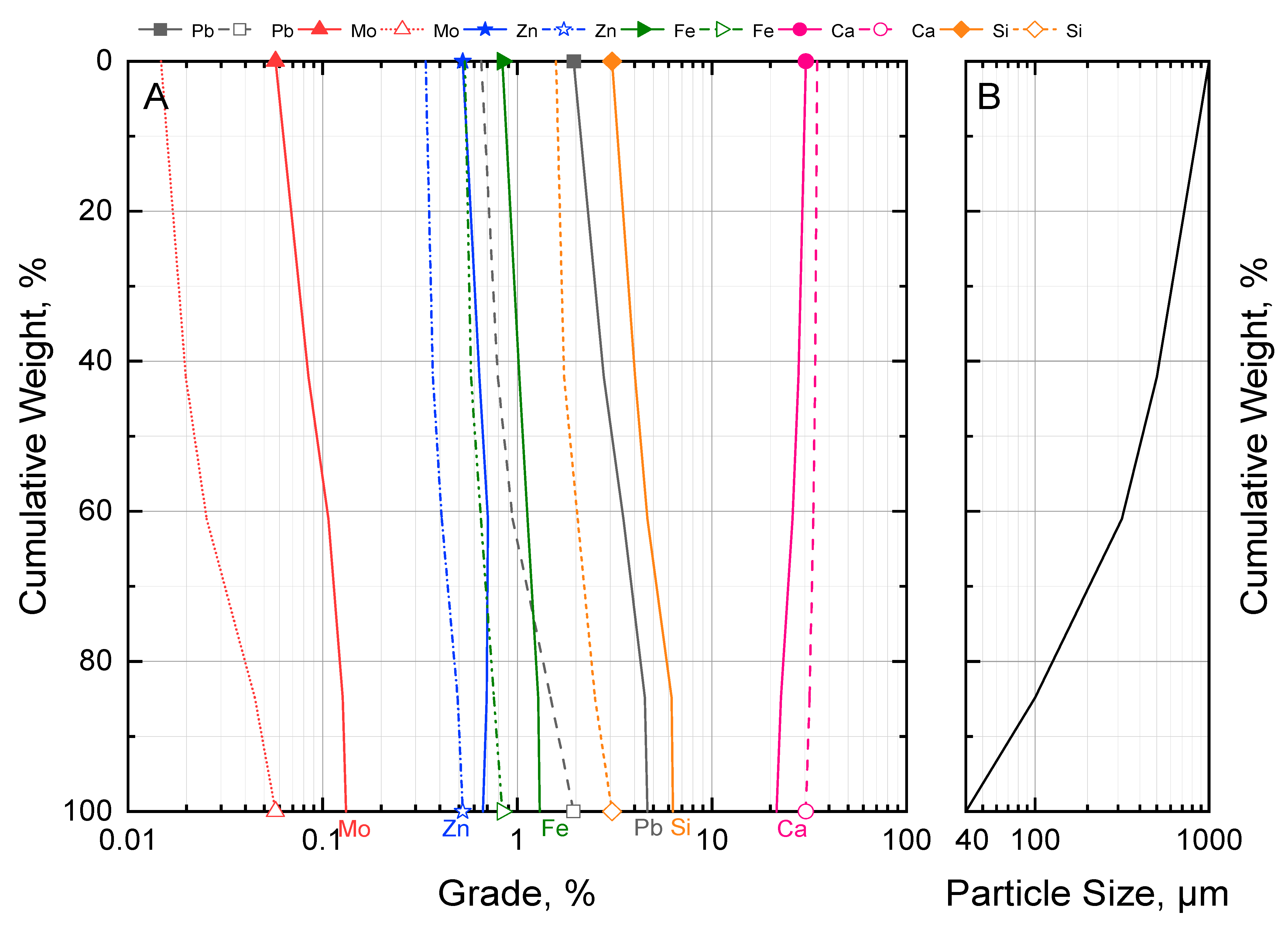
The HR plot in Figure 8 illustrates the characteristic curves for the fraction between 1 mm and 40 µm of the sample “A1 top”. The remaining four size fractions are shown as the step function of the chart, where their mean grades are plotted on the abscissa. This presentation is equally as discontinuous as a tabular one. Finally, area replacement results in the characteristic curves.
In order to obtain the required set point for a desired mass yield, the particle size distribution has been plotted in Figure 8 in the section offset to the right.
In the second stage, the outcome of a series of optimal two-product separations is calculated. The respective set points correspond to the limits used in the fractional analysis. The grades of both products are plotted as a function of the mass yield of the first product. These continuous curves may be called product curves. They show the obtainable grades for any given mass yield.
The undersized and oversized curves are plotted for the same sample in Figure 9. Now, any cut size between 1 mm and 40 µm can be selected to determine the mass yield and the mean grade of the undersized and the oversized product. For example, a screening cut at 200 µm results in a mass yield of about 27% undersized and 73% oversized products. The mean lead grade of the undersized product (solid line) increased from about 1.9% (feed) to about 4.0%. According to the balance, the corresponding recovery is 57%. The mean lead grade of the oversized product (dashed line) decreased to 1.2% with a recovery of 43%.

6.5. Evaluation of the Laboratory Sorting Trials

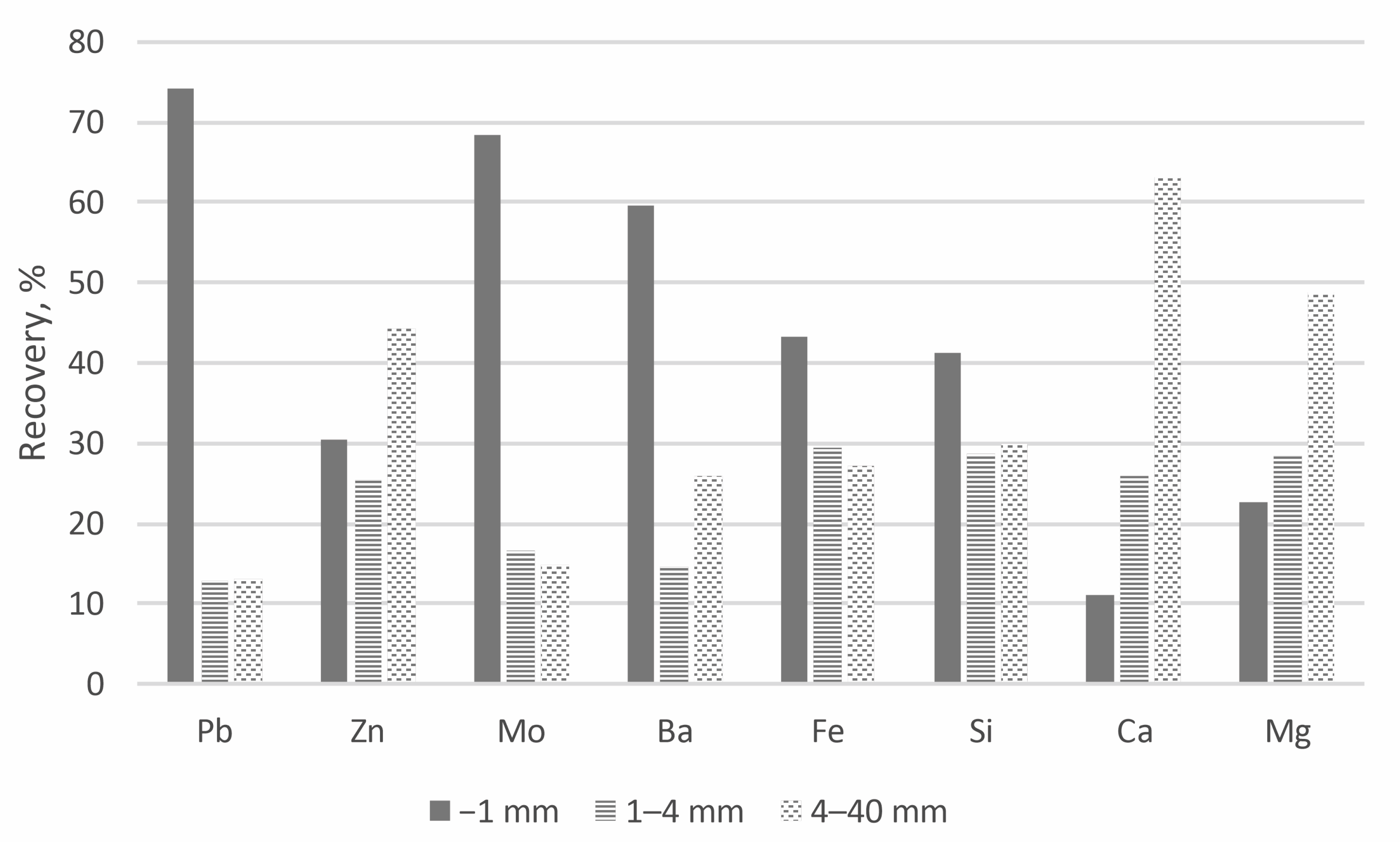
Table 8 shows the grades and distribution of selected components in the deslimed feed size fractions of 30–1000 µm, which were calculated from the sorting products. With the exception of Ca and Mg, all components in the fine fraction of −40 mm have higher grades when comparing the two fractions of −40 mm and +40 mm. This is especially noticeable in the case of lead, molybdenum, and barium, where the grades rise by a factor of around five (Pb), eight (Mo), and four (Ba). The zinc grade in the fraction of −40 mm is only marginally higher. A closer comparison of the individual fractions of −40 mm shows that the finer the particle fraction, the higher the grades, and so the fraction of −1 mm has the highest grades (vice versa for Ca). When the distribution of the components within the separate fractions of −40 mm is examined (as seen in Figure 10), the following may be stated: the fraction of −1 mm contains about 74% of the total Pb and about 68% of the total Mo. The fraction of −1 mm has the highest content of Ba, Fe, and Si, whereas the fraction of 4–40 mm has the highest content of Zn, Ca, and Mg. The contrary behaviour of Zn is an indicator of the finer intergrowth of zinc-bearing minerals.
Table 9 summarises the results of the gravity concentration trials for the elements Pb, Zn, and Mo. The two fractions of the hydraulic classifier were numerically combined to 30–1000 µm for the overall balance presented. The results of the several sorting steps employed were also grouped. For example, the results of the shaking table steps “H1.C,” “H2.C,” and “H3.C” were combined into “Hx.C.” (see Figure 6). The gravity concentration trials can be considered more successful for the elements Pb and Mo than for Zn. As expected, the “heavies” and “middlings” have the highest Pb, Mo, and Zn grades.
The highest grades of Pb and Mo were attained in the uncrushed −1 mm fraction, particularly in the “heavies” of the shaking table (Hx.C). Pb was enriched by a factor of nearly 37 from 0.9% in the feed to 34.1% in the concentrate, with a recovery of 76.2%. The Mo grade was enriched by a factor of 24 from 0.08% in the feed to 1.93% in the concentrate, with a recovery of 50.8%. By processing solely the −1 mm fraction, it is feasible to extract 56.4% of Pb and 34.7% of Mo based on the total content in the −40 mm fraction.
Zinc shows a distinct behaviour when compared to Pb and Mo. The “heavies” of the two coarser +1 mm fractions have the highest Zn grades. The grades are enriched by a factor of 21 and 18 to 4.9% and 3.1%. The recoveries are 17.2% and 25.4%. The Zn grades in the −1 mm fraction are nearly the same in the “heavies” and “middlings,” at 1.8% and 1.6%, with a recovery of 32.9% and 6.5%, respectively. The behaviour of Zn suggests the following: (1) the uncrushed −1 mm fraction is expected to have more weathered minerals than the coarser crushed +1 mm fractions; (2) Zn-bearing minerals have a lower specific gravity than Pb-bearing minerals and are more likely to be found in the “middlings”; and (3) the intergrowth of Zn-bearing minerals in the oxidic material is more complex.
All the shaking table tailings (Hx.1) show a small increase in grade when compared to (Hx.2). The explanation for this phenomenon is most likely intergrowth and the restricted selectivity of very tiny particles. All the “middlings” (W2.MG) and “tailings” (Wx.LG) of the spiral have a high mass yield and, accordingly, contain a high concentrations of Pb, Mo, and, above all, Zn. The reasons for this trend, as with the shaking table tailings, include intergrowth and the low selectivity of the spiral. Additional cleaning steps and comminution may improve the level of recovery.
The results of the coarse +40 mm fraction are similar to those of the 4–40 mm fraction.
As an example, after one shaking table step, it was feasible to obtain product-suitable grades with 53.8% Pb, 4.2% Mo, and 0.8% Zn from the uncrushed 30–315 µm fraction. The recovery of the total content of the −40 mm fraction is 33.7% for Pb, 28.4% for Mo, and the level of Zn recovery is merely 0.34%. Flotation was used during the waste rock ore-processing campaign in 1981 to produce a lead concentrate with 78.9% Pb and 2.1% Zn [15]. The total lead recovery of 34.4% is close to the stated 33.7%; however, the enrichment was considerably more efficient, and the grade was more than 25% higher.
The gravitational concentration process is marked with modest success, particularly for zinc. The shaking table steps could not create a concentrate with a grade higher than 7% Zn. In 1981, the waste rock ore-processing campaign produced a zinc concentrate (sulphuric) with a grade of 56.1% and a total recovery of 83.6% by flotation [15].
Flotation is the method of choice to achieve the sufficient upgrading of minerals. Gravitational concentration is not suited for these samples as a stand-alone process. However, upstream gravitational sorting might assist the flotation process. For the production of a pre-concentrate for flotation, shaking table steps can be omitted. Table 10 shows the results of the pre-concentration trials with spirals only. The results from the “heavies” of the spiral (Wx.SG) of the −1 mm fraction are the most promising. Lead and molybdenum were both enriched by a factor of about four, yielding grades of 4.2% Pb and 0.31% Mo and recoveries of 64.7% and 52.1%. With a recovery of 13.4%, the zinc grade was enhanced by a ratio of 2.3 to 1.3% Zn. In comparison, 1.3% Pb and 5.1% Zn were found in the entire flotation feed from the 1982 Bleiberg flotation [15].

7. Conclusions

The predictions derived from the fractional analysis and the results of the gravity concentration trials are consistent with respect to the gravitational processability of the waste rock dump sample “A1 top”. Pre-concentration is possible, particularly for lead and molybdenum-containing heavy minerals. Further efforts are required to achieve improved recovery. Such efforts comprise particle fraction expansion and the employment of comminution and process stages with multiple spiral or shaking table steps, as demonstrated by the pre-concentration trials.
In this scenario, gravity concentration alone is ineffective for producing commercial concentrates, particularly with respect to zinc. In this regard, flotation is the most promising approach. It may be feasible to use gravitational sorting upstream of flotation to assist the flotation process. Flotation testing is currently in progress. The challenge with flotation is the very fluctuational degree of wettability caused by mineral weathering.
The valuable mineral content of these waste rock dumps varies widely, and the selection of the appropriate processing technique is dependent on a number of factors. The additional cost of comminution to a particle size suitable for flotation is highly dependent on the current market and energy prices. The determination of whether a method is economically feasible for an eventual reprocessing of waste rock dumps must be evaluated separately. Finally, the transmission of possible contaminants must also be considered when reprocessing waste rock dumps, particularly when using comminution and flotation processes.

Author Contributions

L.M.: conceptualization, methodology, investigation, writing—original draft preparation, visualisation, data curation, and project administration. S.D. and S.E.: mineralogy, investigation, and writing. W.Ö.: reviewing and editing. H.N.: investigation, reviewing, and editing. H.F.: supervision, reviewing, and editing. F.M.: supervision, reviewing, and editing. All authors have read and agreed to the published version of the manuscript.

Funding

The investigations described were carried out as part of a COMET project “COMMBY” (Competence network for the assessment of metal-bearing by-products). The funding body of this programme, grant number 870623, is the Austrian Research Promotion Agency (FFG), which is owned by the Republic of Austria, represented by the Federal Ministry for Climate Action, Environment, Energy, Mobility, Innovation and Technology (BMK) and the Federal Ministry for Labour and Economy (BMAW). Further support was provided by the Styrian Business Promotion Agency (SFG), Burgenland Wirtschaftsagentur GmbH, and the provinces of Burgenland and Styria.

Data Availability Statement

Data are contained within the article.

Acknowledgments

I would like to use this occasion to express my gratitude to Thomas Meisel and Peter Onuk for their invaluable support with the chemical analysis of the mineral samples.

Conflicts of Interest

The authors declare no conflict of interest.

References

  1. Jicha, H.L. Alpine lead-zinc ores of Europe. Econ. Geol. 1951, 46, 707–730. [Google Scholar] [CrossRef]
  2. Schneider, H.J. Facies Differentiation and Controlling Factors for the Depositional Lead-Zinc Concentration in the Ladinian Geosyncline of the Eastern Alps. Dev. Sedimentol. 1964, 2, 29–45. [Google Scholar] [CrossRef]
  3. Maucher, A.; Schneider, H.-J. The Alpine Lead-Zinc Ores. In Genesis of Stratiform Lead-Zinc-Barite-Fluorite Deposits (Mississippi Valley Type Deposits); Society of Economic Geologists: Littleton, CO, USA, 1967; Volume 3, pp. 71–89. [Google Scholar]
  4. Brigo, L.; Kostelka, L.; Omenetto, P.; Schneider, H.-J.; Schroll, E.; Schulz, O. Comparative Reflections on Four Alpine Pb-Zn Deposits. In Time- and Strata-Bound Ore Deposits; Springer: Berlin/Heidelberg, Germany, 1977; pp. 273–293. [Google Scholar] [CrossRef]
  5. Cerny, I. Die karbonatgebundenen Blei-Zink-Lagerstätten des alpinen und außeralpinen Mesozoikums. Die Bedeutung ihrer Geologie, Stratigraphie und Faziesgebundenheit für Prospektion und Bewertung [The Carbonate-bonded Lead-Zinc Deposits of the Alpine and extra-Alpine Mesozoic]. The Significance of their Geology, Stratigraphy and Facies-binding for Prospecting and Evaluation. Arch. Lagerstättenforsch. Geol. Bundesanst. 1989, 11, 104–113. [Google Scholar]
  6. Schroll, E. Mineralisation der Blei-Zink-Lagerstätte Bleiberg-Kreuth (Kärnten) [Mineralisation of the Bleiberg-Kreuth Lead-Zinc Deposit (Carinthia)]. Aufschluss. Z. Freunde Mineral. Geol. 1984, 35, 339–350. [Google Scholar]
  7. Cerny, I.; Schroll, E. Heimische Vorräte an Spezialmetallen (Ga, In, Tl, Ge, Se, Te und Cd) [Domestic Reserves of Special Metals (Ga, In, Tl, Ge, Se, Te and Cd)]. Arch. Lagerstättenforsch. Geol. Bundesanst. 1995, 18, 5–33. [Google Scholar]
  8. Schroll, E. Über Minerale und Spurenelemente, Vererzung und Entstehung der Blei-Zink-Lagerstätte Bleiberg-Kreuth/Kärnten in Osterreich [About Minerals and Trace Elements, Mineralization and Genesis of the Lead-Zinc Deposit Bleiberg-Kreuth/Carinthia in Austria]. Mitt. Osterr. Mineral. Ges.-Sonderh. 1953, 7, 73. [Google Scholar]
  9. Zeloth, T. Zwischen Staat und Markt Geschichte der Bleiberger Bergwerks Union und ihrer Vorläuferbetriebe [Between State and Market History of the Bleiberger Bergwerks Union and its predecessor companies]. Verl. Kärntner Landesarch. 2004, 1, 15–31. [Google Scholar]
  10. Schroll, E. Neues zur Genese der Blei-Zink Lagerstätte Bleiberg [News on the Genesis of the Bleiberg Lead-Zinc Deposit]. Carinthia II-tl. 2 2006, 196, 483–500. [Google Scholar]
  11. Schroll, E. Über die Anreicherung von Mo und V in der Hutzone der Pb-Zn-Lagerstätte Bleiberg-Kreuth [On the Enrichment of Mo and V in the Alteration Zone of the Bleiberg-Kreuth Pb-Zn Deposit]. Verh. Geol. Bundesanst. 1949, 139, 138–157. [Google Scholar]
  12. Marousek, L.; Öfner, W.; Flachberger, H. Zu Fragen der Charakterisierung und Aufarbeitung metallhaltiger Rest- und Kreislaufstoffe aus aufbereitungstechnischer Sicht – Vorstellung eines Dissertationsvorhabens [Characterization and Processing of Metal Bearing By-products in Consideration of Mineral Processing Aspects]. BHM Berg-Und Hüttenmännische Mon. 2020, 165, 598–607. [Google Scholar] [CrossRef]
  13. Schroll, E. Blei-Zink-Lagerstätte Bleiberg: Die Geschichte ihrer Erforschung [Bleiberg Lead-Zinc Deposit: The History of its Exploration]. Carinthia II-Sonderhefte 2008, 62, 1–286. [Google Scholar]
  14. Scherer, J. Blei-Zink-Haldenbeprobung, Bleiberger Sonnseite [Lead-Zinc Dump Sampling, Bleiberger Sonnseite]; Montanuniversität Leoben: Leoben, Austria, 1979. [Google Scholar]
  15. Jedlicka, K. Haldenerzgewinnung und -verarbeitung beim Bergbau Bleiberg/Kreuth der Bleiberger Bergwerksunion AG [Waste Rock Ore Mining and Processing at the Bleiberg/Kreuth Mine of Bleiberger Bergwerksunion AG]. BHM Berg-Und Hüttenmännische Mon. 1983, 128, 477–483. [Google Scholar]
  16. Land Kärnten. KAGIS. 2022. Available online: https://kagis.ktn.gv.at/ (accessed on 1 November 2022).
  17. Bergmännischer Kulturverein Bad Bleiberg. Der Weg des Erzes [The Way of the Ore]. 2022. Available online: https://www.bergbauverein-bad-bleiberg.at/der-weg-des-erzes/ (accessed on 1 November 2022).
  18. ISO 3310-1:2016; Test Sieves-Technical Requirements and Testing—Part 1: Test Sieves of Metal Wire Cloth. Beuth Verlag: Berlin, Germany, 2017. [CrossRef]
  19. Wills, B.A.; Finch, J.A. Chapter 11—Dense Medium Separation (DMS). In Wills’ Mineral Processing Technology, 8th ed.; Wills, B.A., Finch, J.A., Eds.; Butterworth-Heinemann: Boston, MA, USA, 2016; pp. 245–264. [Google Scholar]
  20. TC-Tungsten Compounds. Sodium Polytungstate at a Glance: Facts + Advantages. 2020. Available online: https://www.heavy-liquid.com/en/faq/ (accessed on 25 August 2021).
  21. Steiner, H.J. Probenahmetheorie für die Probenahmepraxis [Applied Sampling Theory]. BHM Berg-Und Hüttenmännische Mon. 1999, 144, 224–229. [Google Scholar]
  22. Böhm, A. Gutstrominvariante zur Auslegung inkrementaler Probenahmeeinrichtungen—Hintergrund und Einsatzbeispiele [Bulk Stream Invariants for Designing Incremental Sampling Devices—Basics and Examples]. BHM Berg-Und Hüttenmännische Mon. 2012, 157, 236–243. [Google Scholar] [CrossRef]
  23. Gy, P. Sampling of heterogeneous and dynamic material systems: Theories of heterogeneity, sampling, and homogenizing. Data Handl. Sci. Technol. 1992, 10, 56–102. [Google Scholar]
  24. Visman, J.; Parkinson, J. Part 1: Sampling. In Coal Preparation, 5th ed.; Leonard, J.W., III, Hardinge, B.C., Eds.; Society for Mining, Metallurgy, and Exploration, Inc.: Baltimore, MD, USA, 1991; pp. 866–876. [Google Scholar]
  25. Wills, B.A.; Finch, J.A. Chapter 3—Sampling, Control, and Mass Balancing. In Wills’ Mineral Processing Technology, 8th ed.; Wills, B.A., Finch, J.A., Eds.; Butterworth-Heinemann: Boston, MA, USA, 2016; pp. 41–90. [Google Scholar]
  26. Schubert, H. (Ed.) Handbuch der Mechanischen Verfahrenstechnik [Handbook of Mechanical Process Engineering], 1st ed.; WILEY-VCH Verlag GmbH & Co. KGaA: Weinheim, Germany, 2003; pp. 622–626. [Google Scholar]
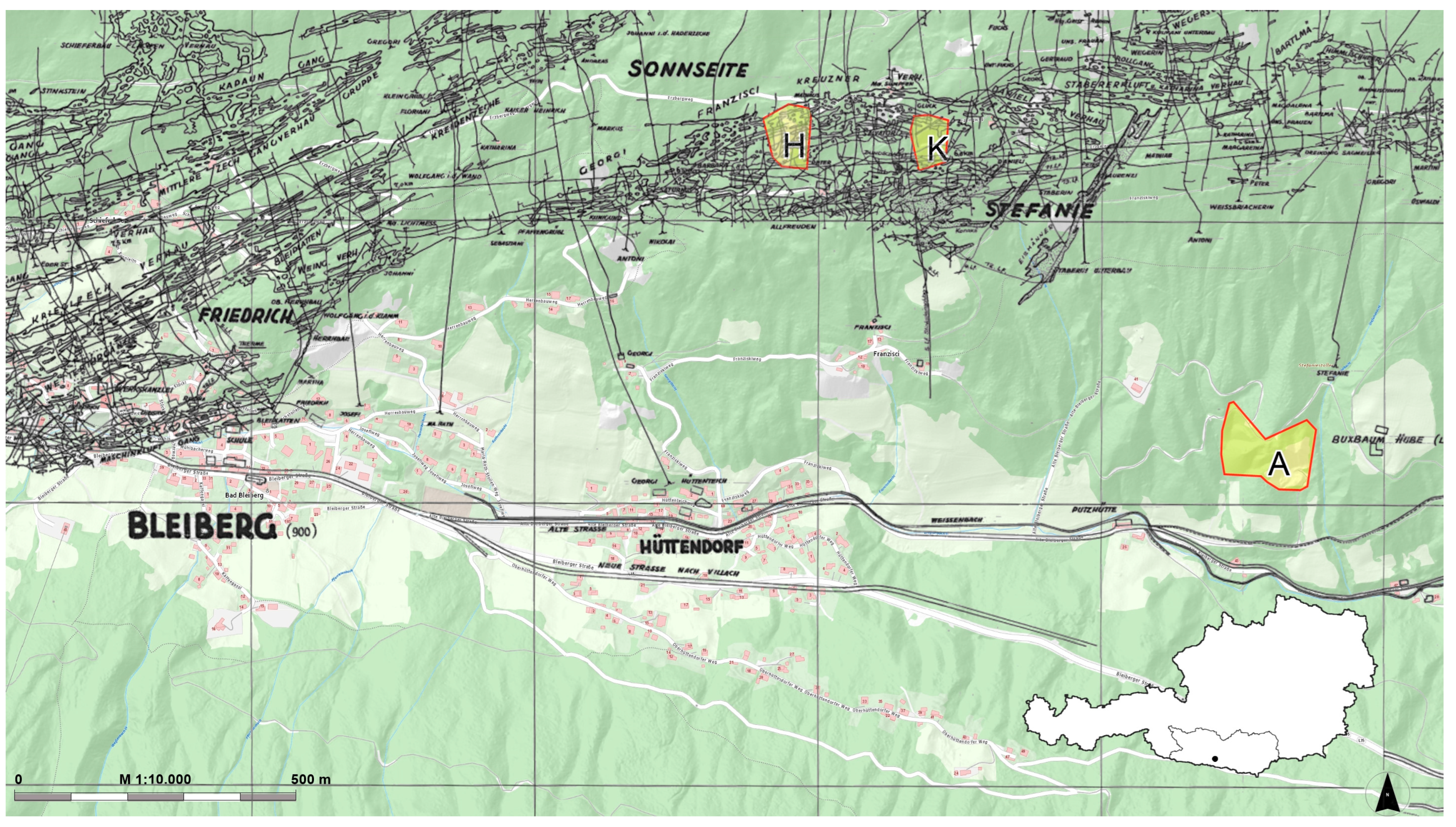
Figure 1. This map segment shows the historical mining map as a black overlay on the current base map. The highlighted areas are the investigated waste dumps (A, H, and K). Overlay created with images from [16,17]. Image from [17] was reproduced with permission from GKB Bergbau GmbH.
Minerals 13 00361 g001
Figure 2. The on-site sampling procedure of the waste rock dumps.
Minerals 13 00361 g002
Figure 3. Second on-site sampling survey. Sampling using a walking excavator and a custom-built sample cart on a winch—top left and right. Bottom left—screening at 40 mm; bottom right—crushing of coarse particles +40 mm.
Minerals 13 00361 g003
Figure 4. Sieve analysis and sink–float analysis results in a two-dimensional fractional analysis.
Minerals 13 00361 g004
Figure 5. Flowchart of comminution and classification steps. Fractions 1, 2, and 3 resulted from the sample “A1 top −40 mm”. Fraction 4 is the coarser sample “A1 top +40 mm” (see Table 2). The fines −1 mm of the pre-crushed sample A1 top +40 mm were blended with the comminution product and not handled separately.
Minerals 13 00361 g005
Figure 6. Flowchart of gravity concentration trials. Not all samples were fed to the second (H2) or third (H3) shaking tables (dashed lines) if the mass was insufficient for the following chemical analysis.
Minerals 13 00361 g006
Figure 7. Particle size distribution (A). Correlation between particle size and density of particles −40 mm (B). Waste dump: A = “Altstefanie, H = “Matthäus”, and K = “Glück”.
Minerals 13 00361 g007
Figure 8. Characteristic curves of the Henry–Reinhardt-plot (A) shows the distribution of elements according to particle size. Note: Correct area replacement requires linear grade-axis. Particle size distribution (B).
Minerals 13 00361 g008
Figure 9. Henry–Reinhardt-plot shows the undersized and oversized curves for the sample “A1 top” (A). Solid lines with full markers represent undersized product grades and dashed lines with blank markers represent oversized product grades. The position of the markers indicates the average feed grades. Particle size distribution (B).
Minerals 13 00361 g009
Figure 10. Distribution of selected components within the size fractions −1 mm, 1–4 mm, and 4–40 mm for sample A1 top.
Minerals 13 00361 g010
Table 1. A summary of the waste rock dump sample units.
Nr.DumpSampleFractionTreatment On-Site
mm
1Altstefanie, AA1 top−40screened
2A1 top+40screened and crushed
3A1 base−40screened
4A1 base+40screened and crushed
5Matthäus, HH1−40screened
6H2+40screened and crushed
7Glück, KK1−40screened
8K2+40screened and crushed
Table 2. Prepared samples −1 mm for comparative gravity concentration trials.
SampleIndexOriginal FractionDescription
A1 top −40 mm1−1 mmuncrushed sample—used as present on waste dumps
21–4 mmground in lab
34–40 mmcrushed and ground in lab
A1 top +40 mm4+40 mmpre-crushed on-site, and crushed and ground in lab
Table 3. Gravity concentration devices and their used settings.
DeviceSettings
Spiral
(Krebs, five turns, height 2.05 m, diameter 630 mm)
Feed pulp, 15% solids by weight
Water flow rate, 816 L/h
Splitter angle 0°
Shaking Table
(Krupp K 1794 250 mm × 500 mm)
Feed pulp, 22% solids by volume
Wash water 200 L/h
Strokes per minute: 280, Length 10–12 mm
Table slope, feed-to-tailings discharge: 5°;
feed-to-concentrate discharge: 1°
Table 4. Partial results of analyses of the “pre-sampling”. Data for “Glück” 1–4 mm is not provided.
DumpFractionPbZnMoBaFeCdCuMnGeAs
mm%%%%%ppmppmppmppmppm
Altstefanie, A1–40.240.240.020.310.8134259961.4011
0.5–10.700.290.040.401.04372071131.6112
−0.52.360.770.101.761.77472581733.0325
Matthäus, H1–40.880.770.200.050.64872891181.4218
0.5–12.241.560.280.041.211272721283.9142
−0.59.472.911.060.272.171683172417.6692
Glück, K0.5–11.226.840.142.880.562391871232.9118
−0.54.187.840.655.930.852473151533.4943
Table 5. Result of the sieve analysis using the example of “A1 top” with indication of the deviation with a statistical certainty of 95% and the corresponding inhomogeneity.
Particle SizeWeightDeviationInhomogeneity
mm%%-ptskg%2
40 --
208.471.0323.08
1021.300.515.70
431.170.231.11
126.020.180.71
0.54.470.180.70
0.3152.000.180.70
0.12.520.180.70
0.041.610.180.70
00--
Table 6. Sink–float analysis results of all four waste rock dump samples.
Specific Gravity Fraction, g/cm3Weight, %Mean Density, g/cm3
Size Fraction, µmSize Fraction, µm
500–1000315–500100–31540–100500–1000315–500100–31540–100
A1 top−2.677.711.911.517.82.712.682.672.64
2.67–389.182.876.066.02.732.732.742.76
+3.03.25.212.516.24.284.394.394.73
Total100.0100.0100.0100.02.762.782.862.93
A1 base−2.6711.76.610.220.92.692.682.672.63
2.67–384.888.277.563.02.732.732.742.77
+3.03.45.212.316.24.294.354.634.86
Total100.0100.0100.0100.02.762.782.872.94
K1−2.6714.710.85.110.32.762.772.772.37
2.67–362.056.350.045.42.762.772.802.83
+3.023.232.845.044.33.993.993.993.95
Total100.0100.0100.0100.02.973.083.233.16
H1−2.6711.811.88.67.92.742.752.732.38
2.67–380.876.968.459.02.742.752.762.77
+3.07.411.323.033.14.054.214.405.24
Total100.0100.0100.0100.02.812.873.023.23
Table 7. Forecast results of gravity separation of the combined particle size fraction 0.04–1 mm—Sample A1 top.
Sp.G.
Fraction
Sp.G.
g/cm3
Mass Yield
%
Grade
%
Recovery
%
Grade ppmRecovery
%
Grade
%
Recovery
%
Grade
%
Recovery
%
PbMoZnFe
−2.672.6710.950.191.04 340.650.204.262.3831.07
2.67–3.02.7381.270.156.35 131.870.1219.020.2625.05
+3.04.477.7823.1592.61 716497.485.1776.724.7243.88
Total2.81100.001.95100.00 572100.000.52100.000.84100.00
BaCaMgSi
−2.672.6710.950.030.259.943.581.136.5321.5977.08
2.67–3.02.7381.270.042.2335.5195.032.1291.240.6918.19
+3.04.477.7817.1797.525.411.390.542.221.894.73
Total2.81100.001.37100.0030.37100.001.89100.003.07100.00
Table 8. Grades and distribution of selected components within the deslimed size fractions 30–1000 µm, sample A1 top.
Original
Fraction
Mass Yield, %Grade, %Recovery, %
ScreeningPbZnMo, ppmBaPbZnMoBa
−1 mm13.040.930.567901.5974.1030.3868.3459.59
1–4 mm26.020.080.24 970.2012.8025.3416.6714.59
4–40 mm60.940.040.18 370.1513.1044.2814.9925.82
Total −40 mm100.000.160.241510.35100.00100.00100.00100.00
+40 mm100.000.030.20 190.09100.00100.00100.00100.00
FeSiCaMgFeSiCaMg
−1 mm13.041.013.8529.671.9943.3941.3810.9822.71
1–4 mm26.020.341.3435.061.2529.4928.6725.8828.48
4–40 mm60.940.130.6036.530.9127.1129.9563.1548.81
Total −40 mm100.000.301.2135.261.14100.00100.00100.00100.00
+40 mm100.000.130.5635.701.46100.00100.00100.00100.00
Table 9. Balanced results of the gravity concentration trials. The sorted 30–315 µm and 315–1000 µm fractions are combined into the 30–1000 µm fraction for clarity; sample A1 top.
Mass, %Grades, %Recovery, %
ScreeningSorting PbZnMoPbZnMo
Indexj l ljlljlljl
Original fractionMassProductMassSorting productSorting productFraction totalSorting productFraction totalSorting productFraction total
−1 mm13.04Wx.LG21.040.180.390.0134.143.0714.524.413.462.37
W2.MG59.710.130.390.0278.566.3541.4012.5820.2813.86
W2.SG0.000.000.000.0000.000.000.000.000.000.00
Hx.12.510.310.540.0310.830.622.390.730.990.67
Hx.23.050.170.420.0180.560.422.260.690.690.47
Hx.311.620.781.590.1629.747.2232.899.9923.8116.28
Hx.C2.0734.081.781.93476.1656.436.541.9950.7634.69
Total100.000.930.560.079100.0074.10100.0030.38100.0068.34
1–4 mm26.02Wx.LG27.690.060.120.00519.612.5114.063.5612.912.15
W2.MG59.320.030.170.00423.382.9943.3010.9724.064.01
W2.SG4.590.070.390.0064.270.557.531.912.880.48
Hx.10.360.341.750.0441.530.202.710.691.670.28
Hx.20.530.110.370.0120.720.090.850.210.650.11
Hx.36.680.170.510.03214.241.8214.403.6522.033.67
Hx.C0.823.564.940.42336.254.6417.164.3535.805.97
Total100.000.080.240.010100.0012.80100.0025.34100.0016.67
4–40 mm60.94Wx.LG29.660.020.080.00219.152.5113.606.0213.582.04
W2.MG55.420.030.130.00240.875.3642.5418.8324.983.74
W2.SG2.420.000.230.0000.180.023.191.410.000.00
Hx.11.000.080.480.0072.340.312.741.212.000.30
Hx.21.080.050.250.0041.380.181.540.681.140.17
Hx.39.000.040.210.00410.811.4210.984.868.831.32
Hx.C1.420.633.150.12925.283.3125.4211.2649.477.42
Total100.000.040.180.004100.0013.10100.0044.28100.0014.99
Total
−40 mm
100.00Wx.LG28.030.050.120.0048.098.0913.9913.996.556.55
W2.MG56.990.040.180.00614.6914.6942.3842.3821.6221.62
W2.SG2.670.030.300.0030.570.573.323.320.480.48
Hx.11.030.180.610.0181.121.122.622.621.251.25
Hx.21.190.090.320.0090.690.691.581.580.750.75
Hx.38.740.200.510.03710.4610.4618.5018.5021.2721.27
Hx.C1.357.803.160.53864.3964.3917.5917.5948.0848.08
Total100.000.160.240.015100.00100.00100.00100.00100.00100.00
+40 mm100.00Wx.LG27.730.020.130.00113.7613.7617.6017.6014.8114.81
W2.MG58.130.040.160.00164.6964.6945.4845.4819.5719.57
W2.SG4.210.040.520.0075.545.5410.8310.8315.9115.91
Hx.10.520.060.730.0030.900.901.861.860.870.87
Hx.20.760.040.320.0031.051.051.181.181.191.19
Hx.37.960.030.320.0048.488.4812.5412.5415.7015.70
Hx.C0.700.263.060.0895.575.5710.5110.5131.9631.96
Total100.000.030.200.002100.00100.00100.00100.00100.00100.00
Table 10. Balanced results of the gravity concentration with spirals only. The sorted 30–315 µm and 315–1000 µm fractions are combined into the 30–1000 µm fraction for clarity; sample A1 top −40 mm.
Mass, %Grades, %Recovery, %
ScreeningSortingPbZnMoPbZnMo
Indexj l ljlljlljl
Original fractionMassProductMassSorting productSorting productFraction totalSorting productFraction totalSorting productFraction total
−1 mm13.04Wx.LG21.040.180.390.0134.143.0714.54.413.462.37
W2.MG59.710.130.390.0278.566.3541.4012.5820.2813.86
Wx.SG19.254.211.290.31387.3064.6944.0813.3976.2652.12
Total100.000.930.560.079100.0074.10100.0030.38100.0068.34
1–4 mm26.02Wx.LG27.690.060.120.00519.612.5114.063.5612.912.15
W2.MG59.320.030.170.00423.382.9943.3010.9724.064.01
Wx.SG12.980.350.770.04757.007.2942.6410.8163.0310.51
Total100.000.080.240.010100.0012.80100.0025.34100.0016.67
4–40 mm60.94Wx.LG29.660.020.080.00219.152.5113.606.0213.582.04
W2.MG55.420.030.130.00240.875.3642.5418.8324.983.74
Wx.SG14.920.090.520.01539.995.2443.8719.4261.439.21
Total100.000.040.180.004100.0013.10100.0044.28100.0014.99
Total
−40 mm
100.00Wx.LG28.030.050.120.0048.098.0913.9913.996.556.55
W2.MG56.990.040.180.00614.6914.6942.3842.3821.6221.62
Wx.SG14.980.840.700.07277.2277.2243.6243.6271.8371.83
Total100.000.160.240.015100.00100.00100.00100.00100.00100.00
Disclaimer/Publisher’s Note: The statements, opinions and data contained in all publications are solely those of the individual author(s) and contributor(s) and not of MDPI and/or the editor(s). MDPI and/or the editor(s) disclaim responsibility for any injury to people or property resulting from any ideas, methods, instructions or products referred to in the content.