Article

An Underground Mine Safety-Oriented Optimization Model for Mine Tailings Backfill Scheduling Considering Multi-Process and Multi-Cycle Issues

1
School of Civil and Resource Engineering, University of Science and Technology Beijing, Beijing 100083, China
2
Key Laboratory of Ministry of Education for Efficient Mining and Safety of Metal Mines, University of Science and Technology Beijing, Beijing 100083, China
3
Jiaojia Gold Mine, Shandong Gold Group Mining (Laizhou) Co., Ltd., Yantai 261442, China
*
Author to whom correspondence should be addressed.
Minerals 2023, 13(11), 1409; https://doi.org/10.3390/min13111409
Submission received: 4 September 2023 / Revised: 25 October 2023 / Accepted: 1 November 2023 / Published: 3 November 2023
(This article belongs to the Topic Green Low-Carbon Technology for Metalliferous Minerals)

Abstract

:
The backfill mining method is adopted in many mines around the world because it can reliably handle underground mine tailings and eliminate dangers in goafs. It is necessary to improve backfilling resource allocation and efficiency, thereby eliminating safety hazards and providing reliable support for the next stage of mining as quickly as possible. In this paper, we propose a backfill-scheduling optimization model that considers multiple processes, resource constraints, and operating capabilities. The purpose of this model is to minimize the exposure time of goafs. This NP-hard (Nondeterministic Polynomial-time hard) problem has a non-inferior implemented solution through multiple iterations of genetic, crossover, and mutation operations of the genetic algorithm. The results show that the model significantly reduces the backfilling-delay time and backfilling-operation time.

1. Introduction

The traditional method of disposal of tailings is to store them in a tailing dam. However, accidents involving dams that seriously damaged the environment and threatened social safety have occurred in countries such as Canada, Brazil, South Africa, and Tanzania [1,2,3,4]. Backfilling tailings into underground mined areas is a reliable method of tailing disposal [5]. This method can not only be used to handle tailings, but also eliminates the hidden danger of instability in underground goafs [6,7,8,9] in accordance with the current goal of the green, safe, and sustainable development of mines.
Backfill mining technology boasts a considerable historical lineage. Its inception traces back to 1864, when the state of Pennsylvania pioneered water-sand backfill usage in coal mines, primarily to manage surface displacement and prevent goaf collapse, thereby safeguarding church foundations [10]. This methodology garnered global attention, as exemplified by its implementation in renowned mining ventures such as the Watersland mine in South Africa and the North Lyer mine in Australia in 1909 [11]. In Peru, the second largest producer of copper in the world, there are historical records that detail the beginnings of the application of hydraulic filling in an underground mine in the Cerro de Pasco Mine in 1937 [12]. Since the early 1990s, paste-thickened tailings backfills have undergone a rapid evolution in their applications [13].
In China, the origins of waste-rock backfill date to the 1950s. Shuai Li’s classification delineates China’s backfill evolution into three pivotal phases: the initial phase (1960–1980) of employed water and sand backfill; the subsequent phase (1980–2000), which saw the adoption of graded tailings backfill; and the present phase (2000–present), which emphasizes full tailings backfilling [14]. Notable examples of backfill systems in China include the Gansu Jinchuan Longshou Mine Backfill System and the Guizhou Kaiyang Phosphate Mine Backfill System [15,16].
At the start of the 21st century, the formulation of the concept of Industry 4.0 as a rapid change in industrial technologies and social relations, led to the development of further concepts of the Fourth Industrial Revolution (Mining 4.0, Energy 4.0, Transport 4.0) [17]. Mining 4.0 digital technologies lead to the convergence of humans and machines [18]. As a result of this convergence, the influence of the human factor on the functioning of extractive enterprises is significantly reduced since part of the analysis and decision-making process falls under the control of digital systems [19]. This progression has facilitated the integration of automation and intelligent algorithms into the realm of backfilling [20], thereby fostering the evolution of automated and intelligent backfilling procedures [21]. By harnessing monitoring equipment [22], the real-time assessment of material feed volumes, flow rates, concentrations, and material levels can be meticulously conducted [23,24]. Through the implementation of a centralized control system, pivotal processes such as feeding, mixing, and conveying are efficiently managed, allowing for the automatic adjustment of slurry concentrations and proportions. These technological strides enable intelligent control and the automatic tuning of process parameters, culminating in the achievement of unmanned, streamlined, and automated slurry preparation processes.
The establishment of a data sensing, fusion, and comprehensive control platform leads to greater order mining operations [25,26]. Adaptations to production programs based on progress are executed promptly, thereby enabling the refined and judicious managerial oversight of production. Nonetheless, the decision-making processes pertaining to backfilling operations, encompassing the designation of available goafs and the scheduling of backfilling equipment, still heavily rely on manual expertise. The prevailing approach often involves a fixed backfilling strategy, where activation will begin as soon as there are goafs and sufficient resources available. However, this conventional approach falls short of meeting the intricate demands of meticulous mine control.
Effective decision-making necessitates a comprehensive understanding of the intricacies inherent in backfilling operations, primarily centered around the following:
  • Multifaceted backfilling processes and equipment: The backfilling process comprises a series of intricate steps, including dense tailings, slurry formulation, mixing, and conveying. In each process, cyclones, thickeners, filtration equipment, feeders, mixers, transfer pumps, backfill pipes, and monitoring and control equipment may be used [27,28].
  • Diverse slurry composition: The preparation of slurry involves a diverse array of materials, encompassing aggregates, flocculants, cementitious materials, and other additives, such as a water-reducing agent and early strength agent, to achieve the desired properties [29].
  • Heterogeneous mining conditions: Distinct mining methods and varying geological conditions across different locations in the mine engender diverse slurry ratios and may necessitate the implementation of distinct preparation processes [30].
  • Complex constraints on resources and tasks: The regulation of equipment and resources must comply with operational process constraints, and the applicability, availability, and operational efficiency of resources must also be considered.
Similar to most mining operations, the goal of backfill operations is completion in a timely and cost-effective manner while ensuring the strength of the backfilling body [31,32]. The above analysis highlights the inherent complexity of backfill organization. Intelligent decision support for resource allocation and scheduling in backfilling is crucial for enhancing efficiency and maintaining mining operations. By optimizing resource allocation, we can minimize inefficiencies such as job queuing and equipment idleness. This necessitates the integration and optimization of processes like tailing thickening, grading, slurry preparation, slurry mixing, equipment allocation, and task arrangement, thus enabling dynamic scheduling through intelligent adjustments [33]. Therefore, the development of an integrated operational scheduling optimization model is imperative.
Scheduling problems are a subdiscipline of operations research. The earliest application in mines was mathematical planning methods. Patterson [33] optimized open-pit mine transportation using mixed-integer linear programming, minimizing energy consumption while meeting production goals. However, mathematical planning is suitable for scenarios with few constraints and simple solution spaces.
The backfill-scheduling problem is an NP-hard problem, and it is difficult to find the optimal solution in polynomial time [34]. In particular, when the size of the problem increases, the time required for an accurate solution also increases rapidly [35]. Methods for solving such problems include heuristics, exact algorithms, and metaheuristic techniques [36]. Heuristic methods provide fast but suboptimal solutions, exact algorithms guarantee optimal solutions but have high computational requirements, and metaheuristic methods such as genetic algorithms can efficiently search the solution space, balancing solution quality with computational efficiency [37]. Genetic algorithms, inspired by natural selection and evolution mechanisms, simulate genetic inheritance and find close-to-optimal solutions through multi-generation evolution [38]. We chose to use a genetic algorithm to solve the backfill-scheduling problem because it is suitable for addressing issues such as complexity, resource constraints, and security [39]. Its encoding and solving steps will be detailed in subsequent chapters.
In short, the evolution of backfill mining technology has undergone phases encompassing waste-rock backfill, hydraulic backfill, graded tailings backfill, and full tailings backfill. The rise of mining 4.0 has propelled the transition towards automated and intelligent backfilling processes. Research endeavors have centered on novel equipment and systems, aligning with the initial mechanization objectives of reducing the workforce and substituting it with automation. Despite these advancements, the decision-making protocols for backfilling operations continue to adhere to traditional fixed patterns. Intriguingly, research attention towards resource-scheduling optimization for backfilling operations is lacking. In response to this gap, this study is an investigation into scheduling-strategy formulation and model resolution for the intricacies encompassed in backfilling processes, characterized by multi-processes, multi-equipment, multi-materials, and multi-goaf backfilling cycle issues. In this research, the model’s validation was conducted based on a Shandong-based mine.

2. Tailings Backfill Scheduling

2.1. Mining and Backfilling Operation Cycle and Backfill-Scheduling Objectives

Backfill mining constitutes a cyclic process involving mining, backfilling, remining, and refilling, carried out until all recoverable resources are extracted [40]. Timely backfilling is imperative for curtailing the prolonged exposure of goafs, thereby safeguarding mine production.
To restrict the maximal extent of exposed goafs, prudent mining space-time management strategies, like mining one ore block per interval (mine 1 interval 1) or mining one ore block at two intervals (mine 1 interval 2) are implemented in certain mines. In Figure 1, the upward horizontal backfill mining method with the mine 1 interval 1 cycle operational mode is illustrated. The foundation of the working face comprises the backfilling body. The process commences with the extraction of the yellow ore body and involves the subsequent filling of the resultant goaf. After the slurry is cured, the green ore body is mined, with consistent progression. Once all ores at this level have been extracted, the subsequent level, featuring blue ore, is mined using the same extraction pattern.
From the end of the mining process to the accomplishment of backfilling, the roof of the goaf remains exposed and lacks steadfast permanent support, rendering it susceptible to safety mishaps like roof collapse and rock burst. Moreover, the protracted postponement of comprehensive backfilling has adverse ramifications. It directly encumbers subsequent ore mining undertakings, resulting in a constricted production nexus and culminating in financial and resource backlogs.

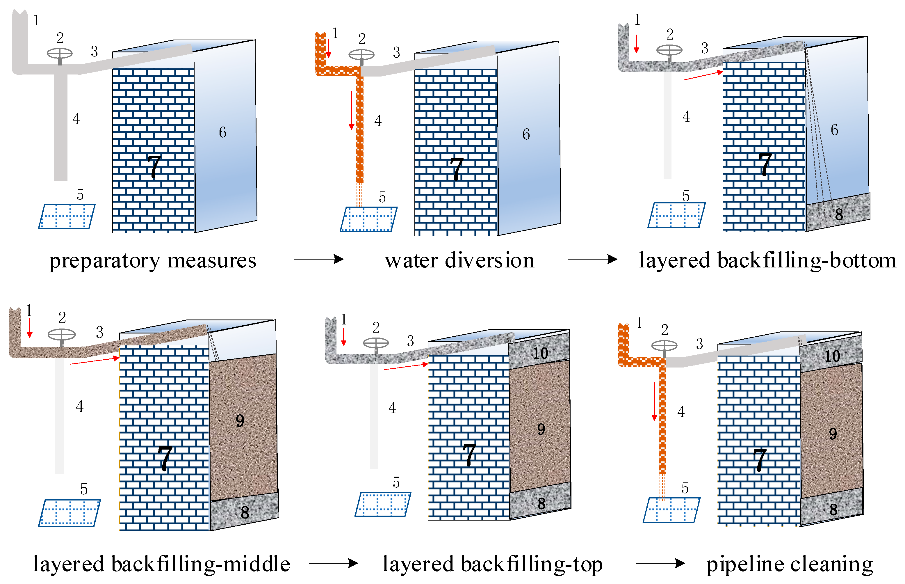
2.2. Backfill Process

Mine backfilling is a multifaceted operation encompassing several stages, materials, types of equipment, and human labor. Each resource can potentially contribute to numerous backfilling processes across one or multiple goafs. To elucidate the intricacies of this process, the backfilling workflow within a singular goaf is systematically outlined below.

2.2.1. Individual Goaf Backfilling Process

Backfilling operations commence once the mining goaf is accepted and the requisite backfilling conditions are established. Following a sequential process, it unfolds in distinct stages, encompassing backfill preparation, water diversion, layered backfilling, and pipeline cleaning.
The Preparatory stages involve the establishment of pipelines within the goaf, linking them to the main pipe network (primary infrastructure), and constructing enclosing walls, these steps mark the initiation of backfilling endeavors. Before introducing the slurry, a preliminary water flush is conducted to identify any pipeline leaks. This water residue also forms a lubricating layer along the pipe walls, reducing resistance during slurry transportation. Layered backfilling [41,42] involves the division of the goaf into distinct vertical strata, each filled with a specific blend of material tailored to the stratum’s characteristics. After the backfilling process, pipeline cleaning ensues, entailing the removal of any residual slurry by flushing the pipelines with water.
Figure 2 illustrates the vertical stratification of the backfilling process into three layers: bottom, middle, and top. Traditionally, the stratified backfilling practice involves employing slurry with elevated ash-sand ratios for the uppermost and lowermost regions of the goaf. Conversely, the middle portion is filled with a low ash-sand ratio slurry or even hydraulic backfill. This approach is based on the superior strength of a high ash-sand ratio backfill, although it is higher in cost due to increased cementitious material consumption. In contrast, a low ash-sand ratio backfill has less strength but requires a lower proportion of cementitious material, thus reducing costs. The layered-backfill methodology effectively balances strength requirements and cost considerations. In Figure 2, we consider two mining sites for reference:
At Shandong’s A Gold Mine, the upward sublevel stoping method is employed with a 30-cm-thick, high-cement-ratio cemented backfill serving as the false bottom for the previous sublevel’s mining. The height of each level is between 3 m and 4 m.
Meanwhile, in the B Gold Mine, a downward sublevel stoping method is employed. A 40-cm-thick high-cement-ratio cemented backfill false bottom is used during subsequent mining. The height of each level is also 3 m to 4 m.

2.2.2. Backfill Resources and Classification

The constituents for backfill encompass aggregates, cementitious materials, and supplementary additives. In the context of underground metal mines, beneficiation tailings predominantly serve as aggregates due to their extensive availability. A singular supply of cementitious materials and additives typically suffices for a designated timeframe. Consequently, the material supply is generally considered sufficient by default. Nevertheless, it remains imperative to evaluate the compatibility of material types with the processing equipment. The slurry preparation procedures encompass diverse operations, including aggregate management, the administration of cementitious materials, the oversight of admixtures, activation mixing, and efficient conveying. The apparatus involved in each of these operations is comprehensively outlined in Table 1.
Each backfilling process necessitates essential critical and supplementary resources. In this paper, we introduce the concept of the “Backfill Unit”, representing the smallest combination of personnel and equipment capable of executing a backfill process. The division of backfill-unit components adheres to the following principles and methodologies:
  • Each backfill unit is equipped to autonomously undertake at least one backfilling process.
  • The resources within the backfill unit are categorized into two types: critical resources and supplementary resources.
  • Critical resources represent assets that are indispensable for the backfill unit’s operation.
  • Supplementary resources possess the capacity to serve multiple backfill units concurrently, and they can support various backfilling processes across multiple goafs.
The outcome of this categorization is succinctly presented in Table 2. The actual number of backfill units is contingent upon the specific circumstances of the mine.
For simplicity, the correlation is abbreviated, and the corresponding relationship is shown in Appendix A at the end of the article.

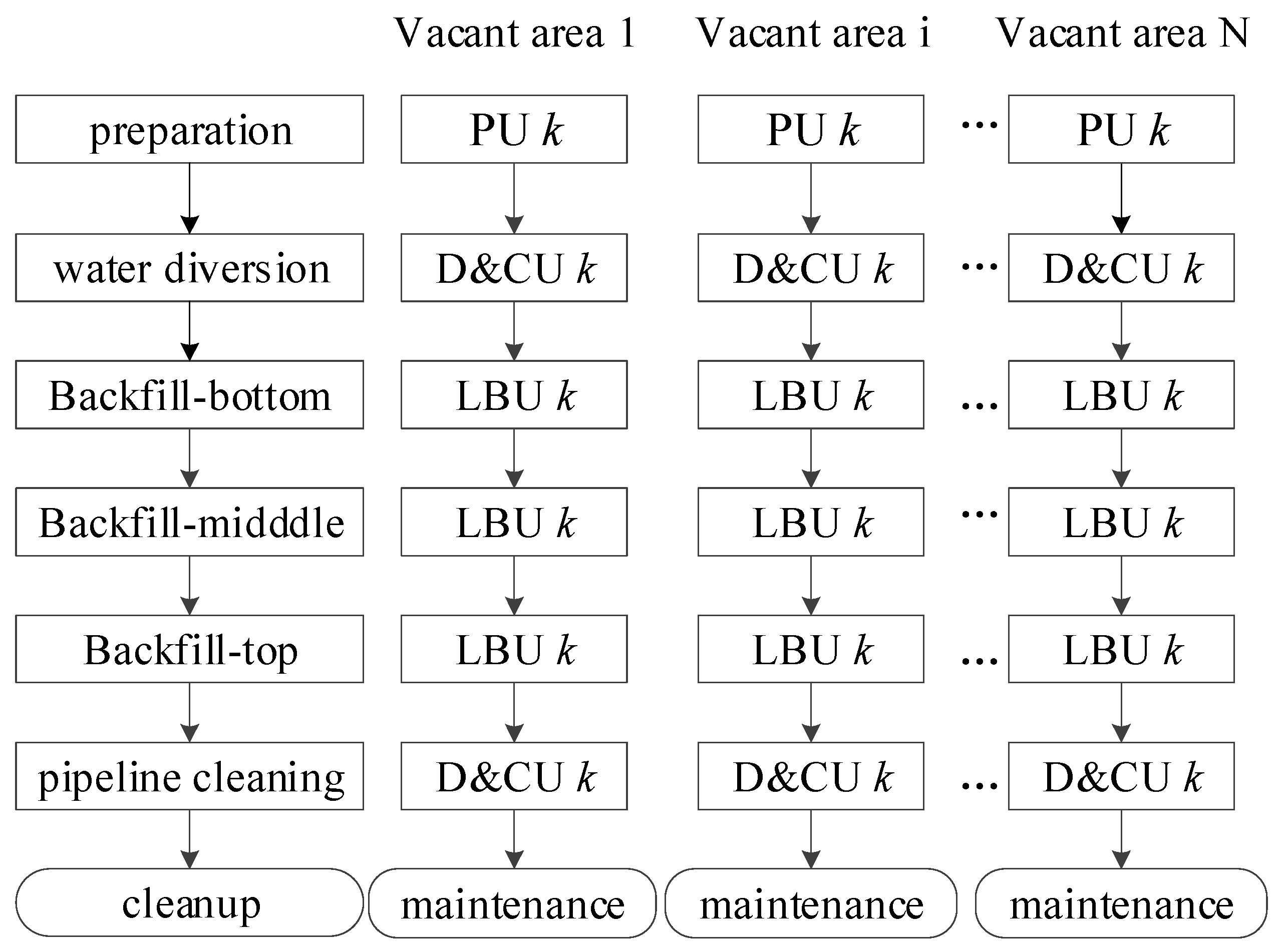
2.2.3. Multi-Goaf Layered-Backfill Operation Mode

The execution of backfilling within a singular goaf necessitates strict adherence to the prescribed sequence of processes. Often, multiple goafs within the mine require concurrent backfilling operations while factoring in equipment capacity to judiciously allocate tasks for each resource, ultimately fulfilling the intended objectives.
In Figure 3, the backfilling process for multi-goafs is outlined with the correspondences of the backfill units, structured into three vertical layers: bottom, center, and top. Notably, the diversion-cleaning unit serves to ensure both the diversion of water and the subsequent pipe-cleaning procedures. The layered backfill unit can be applied in scenarios involving full tailings, graded tailings cemented backfill, or water-sand backfill. In certain mining operations, the classification of layered backfill units may be based on distinctions between aggregates, the presence of cementitious materials, and other factors. It allows the optimization model to account for the interplay between backfill units and cementitious materials.

2.3. Essential Aspects in Optimizing Backfill Scheduling

To enhance the efficacy of backfill scheduling, several key factors must be taken into account. These factors include resource characteristics, equipment capacity, and production safety requirements. When allocating resources, a crucial consideration is striking a balance between goaf safety and operational efficiency. This involves comprehensive management of the backfilling process while adhering to resource constraints, ensuring a well-structured task configuration based on scientific principles. The primary facets of backfilling-resource-scheduling optimization can be summarized as follows:
  • Holistic attainment of scheduling objectives: The temporal exposure of goafs comprises two distinct segments: the duration from goaf acceptance to backfill initiation, referred to as the backfill delay time, and the actual backfill operation time. By orchestrating the overall backfilling progress from a macroscopic standpoint, and judiciously allotting backfill tasks, the overarching goal lies in curtailing both the backfill delay time and operation duration.
  • Interplay constraints between processes and resources: The focus of the optimization model should extend beyond coupling constraints among backfilling processes alone. Equally vital is the consideration of process-continuity requisites. Given the stringent sequence underpinning the process, backfilling operations must remain uninterrupted even in non-emergency circumstances. This prevents gradual slurry condensation within pipelines, limiting the potential for pipeline blockages. Thus, the harmonization of tasks and available resources within intricate operational confines becomes essential for avoiding conflicts between operational tasks and resource utilization.
  • Influence of individual-resource disparities: The preparation capacity of slurry is inherently diverse across various equipment types due to factors like construction timelines, equipment models, and operational upkeep. Effective scheduling demands the consideration of individual unit operational capacities, facilitating the judicious allocation of tasks.
  • Enhancing operational efficiency: A strategic approach entails the allocation of substantial goafs to units endowed with robust slurry processing capacities, which significantly reduces operational durations. In structuring task schedules, the delicate equilibrium between operational efficiency and task intensity should be artfully navigated.

3. Optimization Model Construction

The crux of the scheduling quandary lies in a scenario where N goafs necessitate backfilling, comprising M distinct processes for each goaf, with an aggregate of K backfill units at disposal. Each process is reliant on a dedicated unit, which has distinctive temporal requisites. The principal objective is twofold: to ascertain the sequence of operations for every process and the optimal selection of corresponding backfill units. This dual optimization aims to minimize the exposure duration of the goafs.

3.1. Optimization Objective

As previously discussed, the goaf exposure time can be calculated as the difference between the backfill completion time and the goaf acceptance time. The optimization objective can thus be expressed as follows:
f = min i = 1 N E T i M P T i ,
All the parameters in the model and their meanings are shown in Table 3.

3.2. Constraints

Backfilling is a complex process that is affected by multiple constraints and conflicts. In order to ensure the practicability of the model and achieve refined control of the operation process, it is necessary to fully analyze the constraints and conflicts of the backfill process and determine the main factors affecting backfill scheduling and their coupling relationships. The constraint relationship must not only conform to the actual production situation but also simplify the construction process of the mathematical model. The model constraints include the following:
(1)
Earliest available start time constraint:
The backfilling process can not start until after the goaf acceptance.
S T i 1 P T i i ,
(2)
Process continuity constraint: The process j for goaf i shall begin immediately after the previous process has been completed:
S T i j = E T i ( j 1 ) i ,
(3)
Backfill unit availability constraints
A. Backfill unit suitability constraints
Referring to Table 2, specific backfill units are allocated to singular or multiple processes. To gauge the appropriateness of a given backfilling unit, a binary variable A i j k is introduced. A i j k = 1 means that backfill unit k can serve the j backfill step of goaf i.
B. Calculation of operational hours
Mines typically involve two or three-shift operations. The initial backfill preparations require one shift for fulfillment. The variation in water diversion and pipe cleaning time between different goafs is within 1 h. Hence, the durations of the aforementioned three procedures are inherently stable and can be treated as constants, tailored to the specific circumstances of the mine.
The most substantial variability lies in the layered backfill duration, a parameter computed through factors encompassing goaf volume, the slurry loss coefficient, the setting ratio, and the processing capacity of the layered backfill unit.
V i j = A i · H i j · C 1 · C 2 i , j ,
F T i j k = V i j P i j k i , k , 3 j < M ,
Equation (4) is most applicable to rectangular goafs, exhibiting a higher degree of regularity. For instances where the goaf’s shape is markedly irregular, the recommended approach involves the utilization of a 3D laser scanner with an integrated corresponding operational system to accurately ascertain the goaf’s volume.
T i j k = Q T i k ,   j = 1   i , k ,
T i j k = Y T i k ,   j = 2   i , k ,
T i j k = G T i k ,   j = M   i , k ,
T i j k = F T i j k i , k ,   3 j < M ,
Here, j = 1, j = 2, and j = M represent the preparation, water diversion, and pipe-cleaning processes, respectively. While 3 ≤ j < M stands for the layered backfilling process, the count of which hinges on the layers of backfilling specific to each mine.
(4)
Further simplifications and clarifications
This model simplifies the actual situation on site and has the following settings:
  • Upon goaf acceptance, the goaf is ready for backfilling.
  • The main backfill network is the mine’s infrastructure. The preparation process focuses on configuring the pipeline from the main line to the goaf.
  • The dimensions and proportioning parameters for each layer are determined before backfilling.
  • Each goaf is filled and each process is carried out only once.
  • All backfill units are accessible at the initial moment.
  • Each backfill unit serves one process for a single goaf at the same moment.
  • The operation time is computed based on the backfill unit’s daily efficiency.

3.3. Solution Algorithm Design

The complexity of the problem arises from the interplay of multiple backfill units with distinct functions as well as multiple goafs. Considering sequence and continuity constraints, this problem is classified as a typical NP-hard challenge. To address this issue and tackle scheduling problems, as mentioned in the chapter introduction, researchers have employed heuristic and metaheuristic algorithms like particle swarm, ant colony, and genetic algorithms. In this study, we adopted the GA.

3.3.1. Coding Strategy

Coding serves as a crucial mathematical modeling step, translating real-world challenges into abstract problems. It facilitates the translation of feasible solutions within the solution space into a format suitable for exploration using the genetic algorithm. Our coding strategy for the backfill-scheduling optimization encompasses two key aspects:
  • The sequencing of the backfill processes determines their order.
  • The allocation of appropriate backfill units to each process.
These aspects are integrated into a single chromosome, forming a coherent and viable solution.

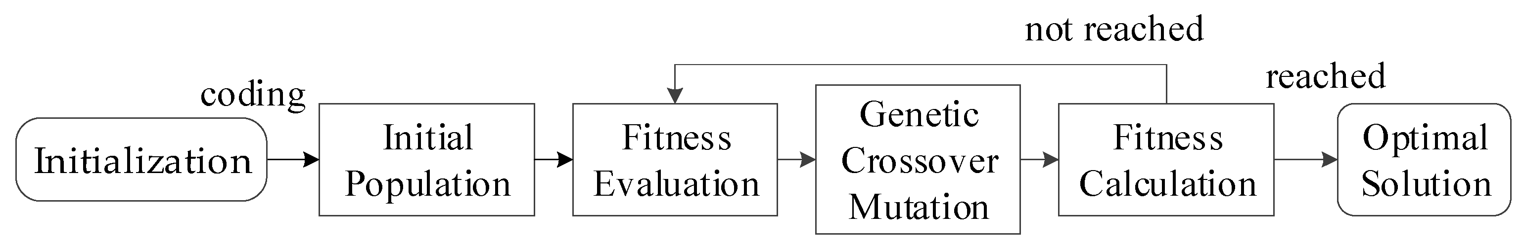
3.3.2. GA Solution Process

Once the encoding phase is concluded, the encoded data enters the GA-solving process, which unfolds as Figure 4.
  • Initialization: Define essential parameters for each goaf, loop, flow, and backfill unit and initialize the overarching parameters.
  • Initial population: Generate random feasible solutions adhering to the stipulated requirements. For this model, one can expedite optimal solution attainment by setting the initial chromosome’s backfilling initiation time to be as close to the goaf acceptance time as possible.
  • Fitness Evaluation: Calculate the fitness value of the population and retain the initial population with the highest fitness value.
  • Crossover: Execute crossover operations based on the predetermined crossover probability.
  • Mutation: Apply mutations to chromosomes according to a designated probability.
  • Fitness Calculation: Determine the fitness of the offspring populations to assess iteration completion. If not reached, merge the selected populations and proceed to step 3. If achieved, proceed to the next step.
  • Optimal Solution Analysis: Choose the chromosome with the greatest fitness. Decode and summarize the data to generate data analysis charts.

4. Case and Result Analysis

A large underground gold mine in China was used as a case study for the validation of the backfill-scheduling optimization model.

4.1. Mining and Backfilling Methods

The mine is located in Shandong Province, China, with proven gold reserves > 200 tons [43]. The annual output is approximately 8 t. Here, disseminated mineralization is combined with veinlet mineralization to form tabular ore bodies that are roughly parallel to the fault zones in the area. The gold deposit has been proven to have six ore bodies, all of which are produced in the footwall of the fault zone. The ore bodies generally strike NE and dip SE, with the No. 1 ore body being the largest and No. 2 being the second largest. The No. 1 ore body accounts for 70.35% of the known gold resources and is located within the middle to upper part of the pyrite–sericite–quartz alteration zone. This ore body strikes 35° NE, dips 34°–44° SE, and extends 1020 m along the strike and 700–1000 m along the dipping direction. It ranges in thickness from 0.95 to 12.08 m (average 6.65 m) and extends downdip from the −10 m level to below the −1050 m level, with a gold grade ranging from 1.74 to 15.4 g/t (average 3.25 g/t). The No. 2 ore body underlies the No. 1 ore body, appearing in the form of regular-pulse, stratiform-like lenses, with a strike of 3°–40° and a dip of 32°–44°. It extends 335–380 m in length, with an average thickness of 5.74 m. The gold grade varies from 1.55 to 24.8 g/t (with an average of 3.13 g/t). The mine has complex conditions, with developed joints and fissures, uneven grade changes, and a surface that cannot subside. For these reasons, the backfill mining method was chosen.
After the completion of the underground development project, a two-step remining process is adopted, first back to the mining room and then back to the mining column. The goaf is vertically segmented into two distinct layers: the lower layer utilizes a slurry with a low cement-to-sand ratio, while the upper layer constitutes an artificial roof slab of 0.4 m in thickness, filled with a slurry possessing a high proportion of cementitious material. Consequently, five discrete stages constitute the backfilling process within the goaf: preparation, water diversion, backfilling-bottom, backfilling-top, and pipe cleaning. Notably, in the upper layer, graded coarse tailings are employed as the aggregate, while in the bottom layer of the second step backfill, full tailings sand is employed.

4.2. Slurry Preparation Station Parameters

This process features a significant enhancement of the slurry preparation station. The original workshop features two layered backfill units processing graded tailings sand at a rate of 60 m3/h. In total, the enhanced workshop boasts four units: two assigned for graded tailings and two for full tailings. All of these units function at an efficient capacity of 100 m3/h. Consequently, six layered backfill units operate within the mine, along with three preparatory units and one diversion and cleaning unit.
Regarding the operational time, the mine’s backfilling preparation stage demands roughly one shift, lasting approximately 8 h. Combined, the water diversion and pipe-cleaning processes require approximately 45 min, with pipe cleaning specifically allocated around 1 h. The layered backfill time is computed based on the volume of the goaf and the backfilling capacity. The core parameters for this mining context are outlined in Table 4.

4.3. Goaf Parameters and Model Inputs

The model hinges on crucial input data: the goaf acceptance time, available backfill unit types and quantities, backfill unit options for each process, and operational timeframes. Weekly backfilling schedules are orchestrated in the mine. Table 5 outlines the mine’s weekly goaf dynamics, characterized by a regular rectangular shape. The mine has a slurry loss rate of 1.05 and a setting ratio of 1.1. All data on goafs come from the mining scheduling and acceptance department of the mine.

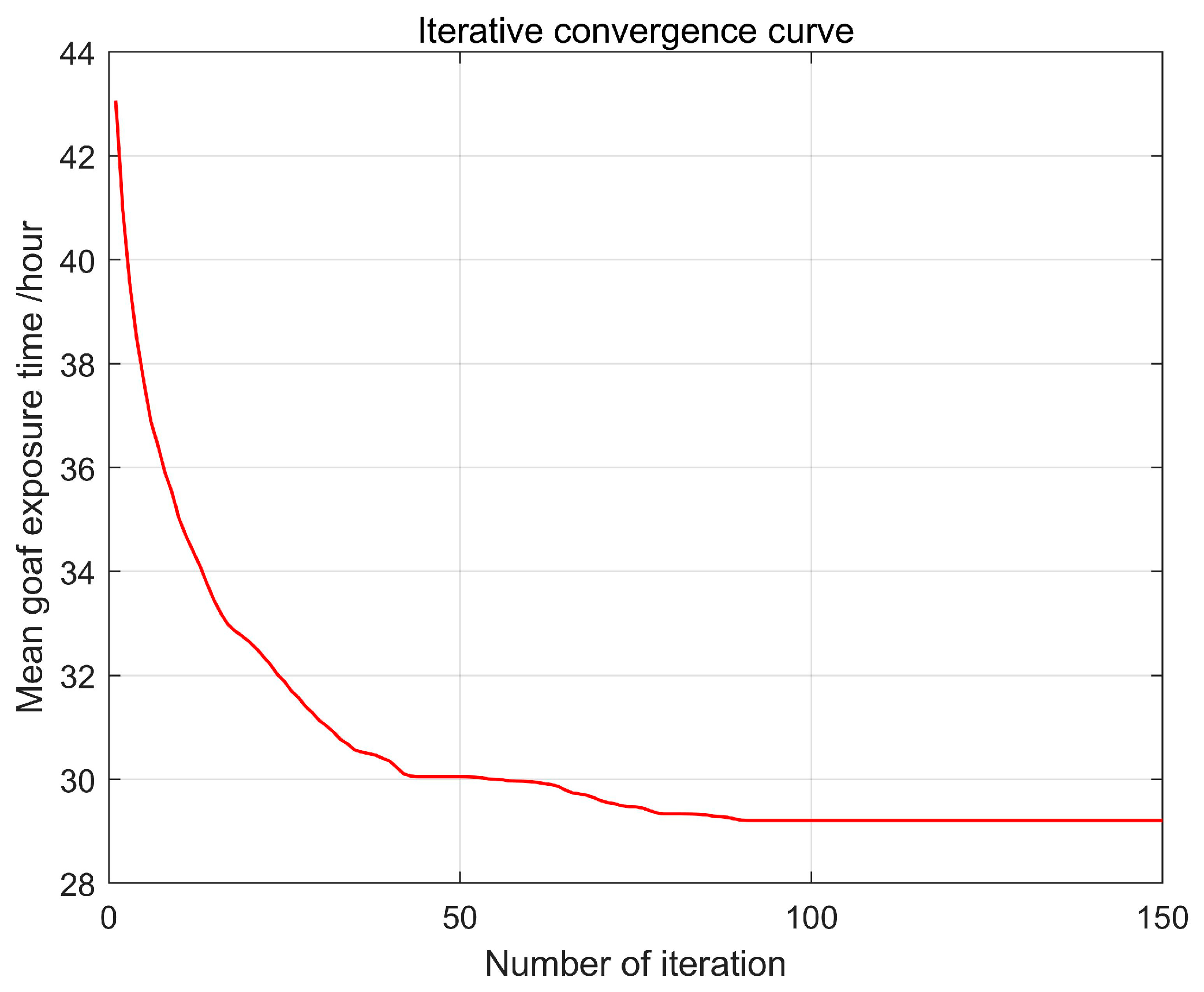
4.4. Model Simulation and Optimization Results

The optimized model was created on a computer with an Intel Core i7-8550U 4 GHz processor and 16 GB RAM. The scenario was simulated through MATLAB R2019a. The GA parameters were configured as follows: a total population of 200, a maximum of 150 evolutionary generations, a crossover probability of 80%, and a mutation probability of 20%. Based on the iterative performance of the optimization model, we generated the iteration curve displayed in Figure 5.
The convergence curve indicates the algorithm’s tendency to stabilize from the 91st generation onward. Remarkably, the initial 43.06-h mean goaf exposure time diminishes to 29.21 h.
In order to visually display the job scheduling of each goaf and backfill unit, we designed Gantt charts. Figure 6 and Figure 7 showcase the backfill process encompassing 24 goafs and the scheduling of 10 backfill units, respectively. In these charts, time is plotted along the horizontal axis, while the vertical axis represents the goaf and backfill unit numbers.
The Gantt chart for backfill unit operations depicts the distribution of tasks among various units. Notably, the newly added stratified backfill units undertake the majority of tasks due to their increased capacity.
Through a combination of on-site data collection and simulation-based techniques, the optimization results for the mine’s backfill scheduling were obtained. The data are presented in detail in Appendix B. The input data were derived from the actual acceptance data of the mine site from the third week of June 2022.
As mentioned earlier, in the traditional scheduling approach implemented at the mine, backfilling typically commenced after the creation of voids in the mining area, contingent on the availability of sufficient backfill resources. This conventional method did not comprehensively consider operational interdependencies and efficiency. Therefore, in comparison to the actual backfill-scheduling data acquired for the mine site, the results derived from the optimization model showed substantial improvements across various dimensions. A comparative analysis is presented in Table 6.
First and foremost, our approach resulted in a remarkable reduction in the exposure time of goafs on a weekly basis. Prior to optimization, the exposure time stood at 874.75 h, a figure that was notably reduced to 701 h following the implementation of the optimized scheduling strategy. This translates to a nearly 20% decrease in the goaf exposure time, representing a significant improvement in operational safety.
Furthermore, the operational duration of the backfill units was also positively impacted, decreasing by 9%. This reduction indicates a notable enhancement in production efficiency.
Another pivotal metric that shows the effectiveness of our approach is the average backfill delay, which was reduced by an impressive 56%, subsequently standing at just 3.625 h. This means that, on average, the most productive units can be scheduled for backfilling within a mere 3 to 4 h after the acceptance of the goaf, significantly expediting the process and streamlining operations.

5. Discussion

In this study, we developed a novel model for optimizing backfill scheduling and employed a GA to solve it. The optimization results have significant practical implications.
Reduction in Exposure Time: One of the most noteworthy achievements of our study is the nearly 20% reduction in the goaf exposure time. This accomplishment has vital implications for safety in mining operations. By reducing the exposure time of mined voids, we can effectively mitigate safety hazards, such as stratum deformation, roof collapse, and the risk of accidents like collapses, rock bursts, and water inflow.
Efficiency Enhancement: Another interesting outcome of our study is the 9% reduction in the overall duration of backfilling operations. We should note that the number and size of the goafs to be backfilled remain constant. The decrease in operational duration equates to an improvement in backfilling efficiency. Our optimization model takes a holistic approach to backfilling task allocation, ensuring that equipment with higher efficiency is allocated tasks with larger workloads, leading to a more rational distribution.
Significant Reduction in Backfill Delay: Another significant achievement is the 56% reduction in the waiting time for each goaf. Mines employing backfilling methods operate in a continuous cycle of mining and backfilling. Timely backfilling completion is crucial to support subsequent mining phases, and the reduction in backfilling delay times further advances the overall mining operation schedule.
Notably, our initial optimization goal was to minimize backfilling waiting time. However, after conducting numerous simulations, it was observed that this optimization goal sometimes led to the extension of the overall duration of the backfilling operation. Consequently, we shifted our focus to minimizing goaf exposure time, which includes not only the backfilling waiting time but also the backfill operation time. As a result, we achieved a more efficient and safer backfilling process.
It is important to note that this model’s application is specific to underground mining processes involving hydraulic backfilling, cemented backfilling, and paste backfilling. Adaptation to a particular mining operation may require localization. Furthermore, to our knowledge, the literature on mine backfilling scheduling optimization is limited. As a result, our study stands as a unique contribution in the absence of comparative references.
Our research results, achieved through a multi-step optimization approach, provide tangible benefits in terms of safety enhancement, operational efficiency, and minimized delays. While our study has specific contextual limitations, it serves as a valuable foundation for future research in the field of mine backfill-scheduling optimization.

6. Conclusions

In this study, we addressed the optimization challenge of mine backfill scheduling within the mining and backfilling operation cycle. A backfill-scheduling model, integrating complex constraints, was constructed to achieve the systematic and precise allocation of backfill resources.
The operational sequence of goafs was systematically segmented into key phases, encompassing backfilling preparation, water diversion, layered backfilling, and pipe cleaning. An exhaustive analysis of the slurry preparation process and essential equipment allowed for the distillation of all backfilling resources capable of executing a specific process into a designated class of backfilling units. Subsequently, a comprehensive model of backfilling cycles across multiple goafs operating concurrently was outlined. The establishment of a corresponding mathematical optimization model, encompassing diverse constraints, and the construction of a robust simulation logic facilitated iterative solving through the genetic algorithm, yielding markedly improved optimization outcomes.
Validation was carried out through a case study involving a significant gold mine in China. The results demonstrated a notable 9% reduction in the backfilling-unit operational time, coupled with a significant 56% decrease in the average delay time, dropping from 8.32 to 3.625 h. Furthermore, the exposure time of the goaf’s roof plates decreased by approximately 20% from 874.75 to 701 h. This substantial reduction not only increased labor efficiency but also underscored the model’s effectiveness and feasibility.
Rational resource allocation substantially curtailed the exposure time of the goaf roof plates, mitigating potential mining hazards. Moreover, the optimization model’s potential for informing mine backfill resource operation decisions and resource protection enhancement is notable. The model’s positive implications for advancing mine sustainability are evident. The proposed method and optimization model serve as critical references for similar scheduling optimization predicaments.
In conclusion, this study provides a pragmatic solution for backfill scheduling within the mining and backfilling operation cycle, contributing substantively to the progress of the mining industry. Future efforts will concentrate on refining the optimization model and algorithm to construct a mine production schedule optimization model aligned with the mining and backfilling cycle, thus fostering continuous development in this field.

Author Contributions

Methodology, G.L.; Model, J.H.; Validation, Y.L.; Resources, G.G., D.P. and Q.Y.; Result analysis, J.H. and Y.L.; Writing—original draft, Y.L.; Writing—review and editing, G.L. and J.H.; Visualization, Y.L.; Supervision, G.L. All authors have read and agreed to the published version of the manuscript.

Funding

This work was funded by the National Key R&D Program of China (No. 2022YFC2903905), the National Natural Science Foundation of China (No. 52074022), and the China Scholarship Council.

Data Availability Statement

Not applicable.

Acknowledgments

We would like to thank Lina Hou with the help of the literature collection.

Conflicts of Interest

The authors declare no conflict of interest.

Appendix A. Some Abbreviations

Full NameAcronym
Nondeterministic Polynomial-time hardNP-hard
Genetic AlgorithmGA
Preparatory UnitPU
Diversion & Cleaning UnitD&CU
Layered Backfill UnitLBU

Appendix B. Result Details

GoafProcessStar TimeEnd TimeBackfill Unit
111.759.753
129.7510.510
1310.516.58
1416.517.59
1517.518.510
21081
2288.7510
238.7514.757
2414.7515.757
2515.7516.7510
3126.7534.752
3234.7535.510
3335.547.57
3447.550.55
3550.551.510
4156642
426464.7510
4364.7577.756
4477.7581.755
4581.7582.7510
5172.7580.752
5280.7581.510
5381.5100.56
54100.5105.55
55105.5106.510
611361443
62144144.7510
63144.75154.757
64154.75157.754
65157.75158.7510
710.758.752
728.759.510
739.541.54
7441.544.59
7544.545.510
8111.7519.751
8219.7520.510
8320.535.57
8435.538.59
8538.539.510
9110.518.53
9218.519.2510
9319.2530.258
9430.2533.255
9533.2534.2510
1018.7516.752
10216.7517.510
10317.533.59
10433.537.55
10537.538.510
11124323
1123232.7510
11332.7544.756
11444.7546.759
11546.7547.7510
12148562
1225656.7510
12356.7591.754
12491.7594.757
12594.7595.7510
13149.557.53
13257.558.2510
13358.2563.256
13463.2565.255
13565.2566.2510
14148.7556.751
14256.7557.510
14357.574.58
14474.577.58
14577.578.510
15172803
1528080.7510
15380.75100.758
154100.75103.758
155103.75104.7510
16183912
1629191.7510
16391.75130.754
164130.75133.759
165133.75134.7510
17198.5106.53
172106.5107.2510
173107.25127.256
174127.25130.256
175130.25131.2510
18196.75104.751
182104.75105.510
183105.5122.57
184122.5125.59
185125.5126.510
191120.75128.751
192128.75129.510
193129.5135.58
194135.5137.54
195137.5138.510
201128.75136.751
202136.75137.510
203137.5147.54
204147.5148.59
205148.5149.510
2111281362
212136136.7510
213136.75147.758
214147.75149.758
215149.75150.7510
2211201282
222128128.7510
223128.75144.757
224144.75146.756
225146.75147.7510
231144.75152.751
232152.75153.510
233153.5166.56
234166.5168.57
235168.5169.510
2411441523
242152152.7510
243152.75168.755
244168.75171.755
245171.75172.7510

References

  1. Owen, J.R.; Kemp, D.; Lèbre Svobodova, K.; Pérez Murillo, G. Catastrophic tailings dam failures and disaster risk disclosure. Int. J. Disaster Risk Reduct. 2020, 42, 101361. [Google Scholar] [CrossRef]
  2. Islam, K.; Murakami, S. Global-scale impact analysis of mine tailings dam failures: 1915–2020. Glob. Environ. Chang. 2021, 70, 102361. [Google Scholar] [CrossRef]
  3. Rana, N.M.; Ghahramani, N.; Evans, S.G.; Small, A.; Skermer, N.; McDougall, S.; Take, W.A. Global magnitude-frequency statistics of the failures and impacts of large water-retention dams and mine tailings impoundments. Earth-Sci. Rev. 2022, 232, 104144. [Google Scholar] [CrossRef]
  4. Cacciuttolo, C.; Cano, D. Spatial and Temporal Study of Supernatant Process Water Pond in Tailings Storage Facilities: Use of Remote Sensing Techniques for Preventing Mine Tailings Dam Failures. Sustainability 2023, 15, 4984. [Google Scholar] [CrossRef]
  5. Cacciuttolo, C.; Atencio, E. Past, Present, and Future of Copper Mine Tailings Governance in Chile (1905–2022): A Review in One of the Leading Mining Countries in the World. Int. J. Environ. Res. Public. Health 2022, 19, 13060. [Google Scholar] [CrossRef] [PubMed]
  6. Emad, M.Z.; Mitri, H.; Kelly, C. State-of-the-art review of backfill practices for sublevel stoping system. Int. J. Mining Reclam. Environ. 2015, 29, 544–556. [Google Scholar] [CrossRef]
  7. Sivakugan, N.; Veenstra, R.; Naguleswaran, N. Underground Mine Backfilling in Australia Using Paste Fills and Hydraulic Fills. Int. J. Geosynth. Ground Eng. 2015, 1, 18. [Google Scholar] [CrossRef]
  8. Benzaazoua, M.; Bussière, B.; Demers, I.; Aubertin, M.; Fried, É.; Blier, A. Integrated mine tailings management by combining environmental desulphurization and cemented paste backfill: Application to mine Doyon, Quebec, Canada. Miner. Eng. 2008, 21, 330–340. [Google Scholar] [CrossRef]
  9. Sari, M.; Yilmaz, E.; Kasap, T. Long-term ageing characteristics of cemented paste backfill: Usability of sand as a partial substitute of hazardous tailings. J. Clean. Prod. 2023, 401, 136723. [Google Scholar] [CrossRef]
  10. Yu, H.; Li, S.; Wang, X. The recent progress China has made in the backfill mining method, part I: The theory and equipment of backfill pipeline transportation. Minerals 2021, 11, 1274. [Google Scholar] [CrossRef]
  11. Yao, Y.; Cui, Z.; Wu, R. Development and challenges on mining backfill technology. Mater. Sci. Res. 2012, 1, 73. [Google Scholar] [CrossRef]
  12. Cacciuttolo, C.; Marinovic, A. Experiences of Underground Mine Backfilling Using Mine Tailings Developed in the Andean Region of Peru: A Green Mining Solution to Reduce Socio-Environmental Impacts. Sustainability 2023, 15, 12912. [Google Scholar] [CrossRef]
  13. Stone, D. The evolution of paste for backfill. In Mine Fill 2014: Proceedings of the Eleventh International Symposium on Mining with Backfill; Australian Centre for Geomechanics: Perth, Australia, 2014; pp. 31–33. [Google Scholar]
  14. Li, S.; Zhao, Z.; Yu, H.; Wang, X. The recent progress China has made in the backfill mining method, Part II: The composition and typical examples of backfill systems. Minerals 2021, 11, 1362. [Google Scholar] [CrossRef]
  15. Zhao, X.; Fourie, A.; Qi, C. Mechanics and safety issues in tailing-based backfill: A review. Int. J. Min. Met. Mater. 2020, 27, 1165–1178. [Google Scholar] [CrossRef]
  16. Yin, S.H.; Shao, Y.J.; Wu, A.X.; Wang, H.; Liu, X.; Wang, Y. A systematic review of paste technology in metal mines for cleaner production in China. J. Clean. Prod. 2020, 247, 119590. [Google Scholar] [CrossRef]
  17. Zhironkin, S.; Gasanov, M.; Suslova, Y. Orderliness in Mining 4.0. Energies 2022, 15, 8153. [Google Scholar] [CrossRef]
  18. Carrasco, Y. Mining 4.0: A Digital Transformation Approach to Mining Sector. In Proceedings of the Conference “Technology Management and Leadership in Digital Transformation—Looking Ahead to Post-COVID Era”, Portland, OR, USA, 7–11 August 2022; pp. 1–6. [Google Scholar]
  19. Zhironkina, O.; Zhironkin, S. Technological and Intellectual Transition to Mining 4.0: A Review. Energies 2023, 16, 1427. [Google Scholar] [CrossRef]
  20. Qi, C.; Fourie, A. Cemented paste backfill for mineral tailings management: Review and future perspectives. Miner. Eng. 2019, 144, 106025. [Google Scholar] [CrossRef]
  21. Feng, J.; Zhang, Z.; Guan, W.; Wang, W.; Xu, X.; Song, Y.; Liu, H.; Su, H.; Zhao, B.; Hou, D. Review of the Backfill Materials in Chinese Underground Coal Mining. Minerals 2023, 13, 473. [Google Scholar] [CrossRef]
  22. Xu, C.; Chen, X.; Dai, W. Effects of Digital Transformation on Environmental Governance of Mining Enterprises: Evidence from China. Int. J. Environ. Res. Public. Health 2022, 19, 16474. [Google Scholar] [CrossRef]
  23. Cacciuttolo, C.; Guzmán, V.; Catriñir, P.; Atencio, E.; Komarizadehasl, S.; Lozano-Galant, J.A. Low-Cost Sensors Technologies for Monitoring Sustainability and Safety Issues in Mining Activities: Advances, Gaps, and Future Directions in the Digitalization for Smart Mining. Sensors 2023, 23, 6846. [Google Scholar] [CrossRef]
  24. Behera, S.; Mishra, D.; Singh, P.; Mishra, K.; Mandal, S.K.; Ghosh, C.; Kumar, R.; Mandal, P.K. Utilization of mill tailings, fly ash and slag as mine paste backfill material: Review and future perspective. Constr. Build. Mater. 2021, 309, 125120. [Google Scholar] [CrossRef]
  25. Zhang, X.; Wu, D.; Lu, H.; Liu, L.; Zheng, S. Improvement of tailings gradation on workability and strength of cemented tailings backfill. Constr. Build. Mater. 2023, 387, 131633. [Google Scholar] [CrossRef]
  26. Liu, L.; Fang, Z.; Qi, C.; Zhang, B.; Guo, L.; Song, K.I. Experimental investigation on the relationship between pore characteristics and unconfined compressive strength of cemented paste backfill. Constr. Build. Mater. 2018, 179, 254–264. [Google Scholar] [CrossRef]
  27. Belem, T.; Benzaazoua, M. Design and application of underground mine paste backfill technology. Geotech. Geol. Eng. 2008, 26, 147–174. [Google Scholar] [CrossRef]
  28. Yang, L.; Wang, H.; Wu, A.; Li, H.; Bruno, T.A.; Zhou, X.; Wang, X. Effect of mixing time on hydration kinetics and mechanical property of cemented paste backfill. Constr. Build. Mater. 2018, 247, 118516. [Google Scholar] [CrossRef]
  29. Panchal, S.; Deb, D.; Sreenivas, T. Mill tailings based composites as paste backfill in mines of U-bearing dolomitic limestone ore. J. Rock. Mech. Geotech. Eng. 2018, 10, 310–322. [Google Scholar] [CrossRef]
  30. Saedi, A.; Jamshidi-Zanjani, A.; Darban, A.K. A review of additives used in the cemented paste tailings: Environmental aspects and application. J. Environ. Manag. 2021, 289, 112501. [Google Scholar] [CrossRef]
  31. Wu, A.; Ruan, Z.; Bürger, R.; Yin, S.; Wang, J.; Wang, Y. Optimization of flocculation and settling parameters of tailings slurry by response surface methodology. Miner. Eng. 2020, 156, 106488. [Google Scholar] [CrossRef]
  32. Walker, W.J.; Montoy, J.; Chatriand, T. Sulfate removal from coalmine water in western Pennsylvania: Regulatory requirements, design, and performance. J. Am. Soc. Min. Reclam. 2015, 4, 73. [Google Scholar]
  33. Liu, L.; Fang, Z.Y.; Zhang, B.; Wang, M.; Qiu, H.; Zhang, X. Development history and basic categories of mine backfill technology. Met. Mine 2021, 3, 1. [Google Scholar]
  34. Liu, G.; Li, L.; Yang, X.; Guo, L. A numerical analysis of the stress distribution in backfilled stopes considering nonplanar interfaces between the backfill and rock walls. Int. J. Geotech. Eng. 2016, 10, 271–282. [Google Scholar] [CrossRef]
  35. Wang, H.; Tenorio, V.; Li, G.; Hou, J.; Hu, N. Optimization of trackless equipment scheduling in underground mines using genetic algorithms. Min. Metall. Explor. 2020, 37, 1531–1544. [Google Scholar] [CrossRef]
  36. Hou, J.; Li, G.; Wang, H.; Hu, N. Genetic algorithm to simultaneously optimise stope sequencing and equipment dispatching in underground short-term mine planning under time uncertainty. Int. J. Min. Reclam. Environ. 2020, 34, 307–325. [Google Scholar] [CrossRef]
  37. Wang, H.; Li, G.; Hou, J.; Chen, L.; Hu, N. A path planning method for underground intelligent vehicles based on an improved RRT* algorithm. Electronics 2022, 11, 294. [Google Scholar] [CrossRef]
  38. Zhou, Y.; Yang, J.J.; Zheng, L.Y. Multi-agent based hyper-heuristics for multi-objective flexible job shop scheduling: A case study in an aero-engine blade manufacturing plant. IEEE Access 2019, 7, 21147–21176. [Google Scholar] [CrossRef]
  39. Li, J.Q.; Duan, P.; Cao, J.; Lin, X.P.; Han, Y.Y. A hybrid Pareto-based tabu search for the distributed flexible job shop scheduling problem with E/T criteria. IEEE Access 2018, 6, 58883–58897. [Google Scholar] [CrossRef]
  40. Huang, S.; Li, G.; Ben-Awuah, E.; Afum, B.O.; Hu, N. A robust mixed integer linear programming framework for underground cut-and-fill mining production scheduling. Int. J. Min. Reclam. Environ. 2020, 34, 397–414. [Google Scholar] [CrossRef]
  41. Cao, S.; Yilmaz, E.; Song, W.; Yilmaz, E.; Xue, G. Loading rate effect on uniaxial compressive strength behavior and acoustic emission properties of cemented tailings backfill. Constr. Build. Mater. 2019, 213, 313–324. [Google Scholar] [CrossRef]
  42. Yu, H.; Li, S.; Wang, X. The Recent Progress China Has Made in the Backfill Mining Method, Part III: Practical Engineering Problems in Stope and Goaf Backfill. Minerals 2022, 12, 88. [Google Scholar] [CrossRef]
  43. Liu, Y.; Yang, L.; Wang, S.; Liu, X.; Wang, H.; Li, D.; Wei, P.; Cheng, W.; Chen, B. Origin and Evolution of Ore-Forming Fluid and Gold-Deposition Processes at the Sanshandao Gold Deposit, Jiaodong Peninsula, Eastern China. Minerals 2019, 9, 189. [Google Scholar] [CrossRef]
Figure 1. Upward horizontal backfill mining method with mine 1 interval 1 cycle mode. Blue: ore; gray: backfill; yellow: the first step of mining; green: the second step of mining; white: goafs.
Minerals 13 01409 g001
Figure 2. Layered backfill process for one goaf. 1—main pipe network, 2—valve, 3—goaf pipe, 4—drainage pipe, 5—drainage well or water-spill channel, 6—goaf, 7—enclosing wall, 8—bottom backfill body, 9—middle backfill body, 10—top backfill body. The red arrow indicates the fluid direction.
Minerals 13 01409 g002
Figure 3. Correspondence between the process and the unit. i ∈ [1, N], k ∈ [1, K].
Minerals 13 01409 g003
Figure 4. GA iteration process.
Minerals 13 01409 g004
Figure 5. GA iteration.
Minerals 13 01409 g005
Figure 6. Gantt chart of goaf backfill process.
Minerals 13 01409 g006
Figure 7. Weekly operation schedule of backfill units in the mine.
Minerals 13 01409 g007
Table 1. List of tailings sand backfill equipment.
BusinessEquipment
aggregate managementCyclones, flocculant pumps, densifiers, sand silos, feeders, measuring instruments
cementitious materials managementAggregate silos, feeders, metering instruments
admixtures managementAdditive silos, feeders, metering instruments
activation mixingMixers, measuring instruments
efficient conveyingTransfer tanks, transfer pumps, backfill networks, metering instruments
Table 2. Division of backfill units.
ProcessBackfill UnitCritical ResourcesSupplementary Resources
preparationPU 1underground crews 1surface crews, efficient conveying
PU iunderground crews i
…PU n
underground crews n
water diversionD&CU 1
water tank/pool 1
surface crews, efficient conveying, underground crews
D&CU nwater tank/pool n
layered backfillingLBU 1aggregate management 1, activation mixing 1surface crews, efficient conveying, underground crews, cementitious materials management, admixtures management, water tank/pool
LBU 2aggregate management 2, activation mixing 2

LBU n

aggregate management n, activation mixing n
pipeline cleaningD&CU 1
water tank/pool 1…surface crews, efficient conveying, underground crews
D&CU nwater tank/pool n
Table 3. Parameters.
NameMeaning
N Number of mine goafs within a specified timeframe
M Number of backfilling processes per goaf
K Number of backfill units
E T i j End time of process j in goaf i. i [1, N], j [1, M]/h
E T i M Backfilling completion time of goaf i. i [1, N]/h
S T i j Backfilling start time of process j in goaf i. i [1, N], j [1, M]/h
S T i 1 Backfilling start time of goaf i. i [1, N]/h
P T i Acceptance time of goaf i. i [1, N]/h
A i j k Binary variable, 1 if backfill unit k can serve process j in goaf i, and 0 otherwise. i [1, N], j [1, M], k [1, K]
Q T i k Time of preparation when using unit k in goaf i, i [1, N], k [1, K]/h
Y T i k Time of water diversion when using unit k in goaf i, i [1, N], k [1, K]/h
G T i k Time of pipeline cleaning when using unit k in goaf i, i [1, N], k [1, K]/h
F T i j k Time of layered backfilling when using unit k in process j of goaf i. i [1, N], j [1, M], k [1, K]/h
A i The base of goaf i. i [1, N]/m2
H i j Layered height in process j of goaf i. i [1, N], j [1, M]/m
C 1 Slurry loss coefficient
C 2 Setting ratio
P i j k Processing capacity of unit k serving process j in goaf i. i [1, N], j [1, M], k [1, K] m3/h
T i j k Time of unit k serving process j in goaf i. i [1, N], j [1, M], k [1, K]/h
Table 4. Basic parameters of the mine.
No.ProcessNumber of UnitsOperating Time (h)
1preparation38
2water diversion10.75
3backfilling-bottom6calculate
4backfilling-top6calculate
5pipe cleaning11
Table 5. Mine goaf information for one week.
No.Mine StepBase (m2)Height (m)Acceptance Time (d)Bottom Slurry Volume (m3)Top Slurry Volume (m3)
12213.42.591539.05 98.59
22149.43.361510.42 69.02
32266.864.2321179.88 123.29
42501.22.531215.66 231.55
52538.83.341804.71 248.93
62330.62.86916.42 152.74
71498.63.6711881.41 230.35
81467.13.0711438.85 215.80
91286.23.4411003.91 132.22
101438.333.4511544.13 202.51
111418.072.8121163.72 193.15
121556.33.6132059.30 257.01
131135.53.43469.51 62.60
1415003.231617.00 231.00
151505.93.7841974.98 233.73
1614714.642284.82 217.60
171477.43.951930.99 220.56
1814383.651618.85 202.36
191173.443.046528.85 80.13
201169.433.226551.85 78.28
211305.43.3461036.34 141.09
221360.24.1861574.26 166.41
231340.23.6171260.52 157.17
241360.82.647933.05 166.69
Table 6. Comparison of indicators before and after optimization.
IndicatorTraditionalOptimizationEnhancement Ratio
Goafs’ exposure time/h 874.7570119.86%
operating time/h6756149.04%
Average delay/h8.323.62556.4%
Disclaimer/Publisher’s Note: The statements, opinions and data contained in all publications are solely those of the individual author(s) and contributor(s) and not of MDPI and/or the editor(s). MDPI and/or the editor(s) disclaim responsibility for any injury to people or property resulting from any ideas, methods, instructions or products referred to in the content.

