Article

Study on Mechanical Characteristics of Rock Surrounding the Roadway under Different Section Shapes

1
Department of Resource Engineering, Heilongjiang University of Technology, Jixi 158100, China
2
State Key Laboratory of Coal Resources and Safe Mining, China University of Mining & Technology, Beijing 100083, China
*
Author to whom correspondence should be addressed.
Minerals 2022, 12(12), 1504; https://doi.org/10.3390/min12121504
Submission received: 21 September 2022 / Revised: 17 November 2022 / Accepted: 22 November 2022 / Published: 25 November 2022
(This article belongs to the Special Issue Green Mining of Coal Mine in China)

Abstract

:
In order to understand the instability characteristics of surrounding rock during deep roadway excavation, the influence of different section shapes on the stability of surrounding rock was systematically analyzed. Four sections of roadway with circular, rectangular, semicircular arch and three-center arch were studied. Simulation revealed that the maximum principal stress concentration and pressure relief degree of the three-center arch roadway is the highest, the minimum principal stress relief degree of the rectangular roadway is highest, the roof subsidence of the semicircular arch roadway is the lowest, the roof subsidence and left and right side displacement of the rectangular roadway are the highest, the surrounding rock failure areas of the circular roadway are evenly distributed, the surrounding rock failure areas of the other shape roadways are arch-distributed and the surrounding rock failure of the two sides of the rectangular roadway is the deepest. The mining stress environment coefficient is defined according to the stress state of the rock surrounding the roadway, and the range in which the coefficient is greater than 0.2 is defined as the destructive danger area. We found that the stability of the rock surrounding a circular roadway is greater than that of a semicircular arch roadway, a three-center arch roadway and a rectangular roadway.

1. Introduction

For a long time, energy shortages have limited the development of the world economy. Coal resources represent the largest reserves and the most widely distributed conventional and strategic energy source. Coal resources account for approximately 25% of the world’s one-time energy consumption [1,2,3]. With the rapid development of the world economy, it is difficult to maintain coal output to support the demand for steel, electricity, chemical and other industrial production, as well as residential demands; therefore, the coal gap is growing. The amount coal resources buried in the shallow part of the Earth is decreasing continuously, and the mining of deep coal resources has become a common practice [4,5,6]. In the complex geomechanical environment of high ground stress, high ground temperature, high osmotic pressure and strong mining disturbance, it is difficult to excavate roadways inside deep rock masses, which are characterized by strong ore pressure, a large amount of surrounding rock deformation and long duration, serious drift floor heave and strong rheology [7,8,9,10,11].
In order to solve the above problems, a considerable amount of scientific research has been conducted with respect to the shape of deep high-stress roadway sections in order to identify and optimize construction methods [12,13,14,15,16]. Li et al studied six roadway section shapes: a rectangle, a straight wall with an arched top, a horseshoe shape, a three-centered arch, an ellipse and a circle. Roadway section shape was found to have a minimal effect on the distribution of principal stress difference. The radius of excavation determines the distribution of the plastic zone; a larger void-reinforced area results in increased deformation of the roadway surface and vice versa. A circle or an ellipse is a reasonable section shape for a high-stress roadway based on the side-pressure coefficient and the orientation of principal stress [17,18,19,20,21]. Xu et al studied the surrounding rock plastic zone distribution and deformation characteristics after the excavation of three types of roadway section, including an inclined roof echelon, a straight-wall half arch and an inclined wall arch roof. Compared with the inclined roof echelon and straight-wall half arch, the excavation of the inclined wall arc roof was reported to be more beneficial in terms of deformation control of the surrounding rock of a gob-side coal-rock roadway with an inclined seam. The influence of excavation on surrounding rock deformation and damage differs for an inclined-wall arc roof of a roadway with varying outward angles; an inclined-wall arc roof with an outward angle 10° results in the least deformation of the surrounding rock after excavation, representing a relatively ideal section shape when the roadway is in use [22,23,24,25,26]. Because the criteria for the selection and optimization of roadway section shapes are not comprehensive and specific, roadway supports are often not effective, with a high support cost. Therefore, in this study, we take the shape of roadway sections as the starting point and investigate four types of roadway, namely round, rectanglular, semicircular arch and three-center arch, all of which are common in coal mines. The influences of the maximum principal stress, minimum principal stress, vertical displacement, horizontal displacement, damage zone and destructive danger area on the stability of rock surrounding roadways were studied by numerical simulation [27,28,29,30,31,32,33].

2. Engineering Background and Numerical Model

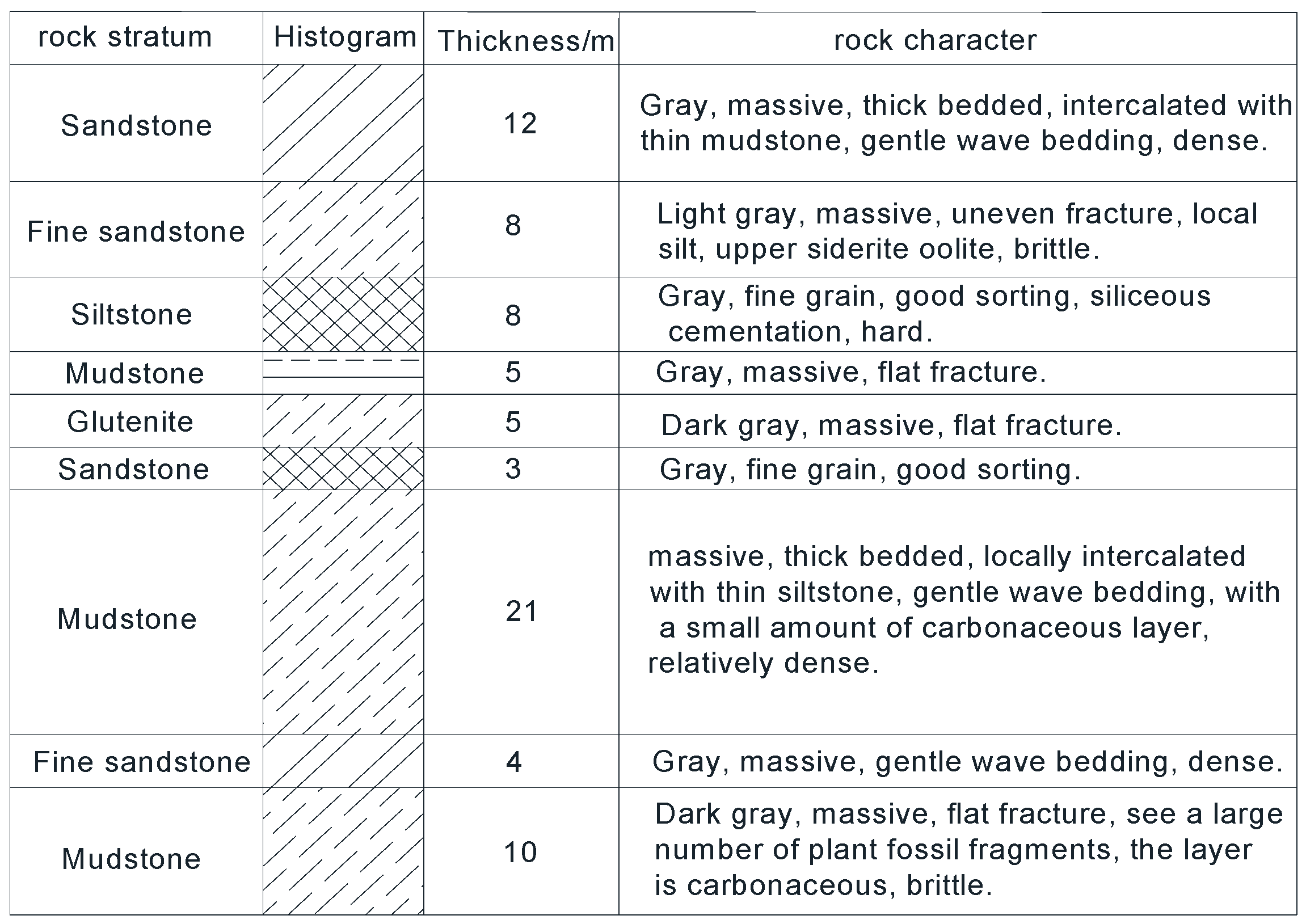
2.1. Engineering Background

The bottom extraction roadway of a coal mine working face was taken as the engineering object in the present study. The main coal seam of the working face is a 2# coal seam with a simple structure and a thickness of 3.4~7.1 m (6.23 m thick on average). The coal seam changes considerably and dips by about 16°. The roof and floor are mostly comprised of thin-layer siltstone, fine sandstone, carbonaceous mudstone and coal line, and the lithology of the floor is mainly fine sandstone, siltstone, glutenite and mudstone. The mine considered in this study is a coal and gas outburst mine. Therefore, a bottom roadway needs to be arranged in advance for predrainage treatment before coal seam mining. The bottom drainage roadway is arranged in the mudstone with a normal distance of 17–31 m from the coal seam. The strata between the bottom drainage roadway and the 2# main coal seam mined are mudstone, fine sandstone, siltstone, mudstone, glutenite and sandstone from top to bottom. The floor strata of the bottom drainage roadway are fine sandstone, mudstone, siltstone and sandstone along the depth; a comprehensive histogram of the rock strata is shown in Figure 1 [34,35,36,37,38].

2.2. Establishment of a Numerical Model

Based on the above engineering background, a three-dimensional spatial numerical model of the bottom drainage roadway was established by using FLAC3D numerical software, as shown in Figure 2. FLAC3D is one of the most commonly used simulation software programs for rock excavation engineering. The built-in Mohr–Coulomb constitutive model can be used to simulate the stress change and displacement change of surrounding rock after rock excavation, as well as the distribution the plastic zone of surrounding rock. The range of the three-dimensional space numerical model of the bottom drainage roadway is 85 m × 65 m × 85 m, 700–780 m deep. A total of nine layers are arranged from top to bottom, including mudstone (12 m), fine sandstone (8 m), siltstone (8 m), mudstone (5 m), medium-grained sandstone (5 m), sandstone (3 m), mudstone (21 m), fine sandstone (4 m) and mudstone (10 m), with each layer dipping by 16°. The physical and mechanical parameters of the rock strata are shown in Table 1.
The bottom drainage roadway is arranged in the middle of the model (the 21 m mudstone of the seventh layer), with an occurrence depths of approximately 740 m. The adopted roadway cross-section shapes are circular, rectangular, semicircular arch and three-core arch, with an excavation length of 60 m. The radius of the circular roadway is 3 m, the side length of the rectangle is 6 m, the diameter of the semicircular arch is 3 m and the radii of the three core arches are 2 m, 4 m and 2 m, respectively. Because the size of the roadway section is much smaller than the numerical model, the boundary effect of the model does not affect the numerical simulation results. The periphery and bottom of the numerical model were set as fixed displacement boundaries, and the top surface was set as a stress boundary applied with 18 MPa compressive stress to simulate the overburden weight, which was not established in the model. The initial ground stress was assigned according to the measured results in the mining area. The maximum principal stress was vertical stress, and the middle principal stress and the minimum principal stress were parallel to the X and Y axes, respectively, with 0.6 and 0.3 side-pressure coefficients. The roadway excavation of surrounding rock is calculated by the Mohr–Coulomb constitutive model.

3. Influence of Section Shape on the Stability of Roadway Surrounding Rock

3.1. Influence of Section Shape on Cloud Distribution of Maximum Principal Stress in Surrounding Rock

As shown in Figure 3, the maximum principal stress decreases in the shallow surrounding rock of the roadway under all four section shapes, and the pressure relief range of the roof and floor is significantly than that of the surrounding rock on two sides. When the section shape is round, the pressure relief area develops evenly in the shallow rock surrounding the roadway. The pressure relief range of the roof and floor of the deep roadway is significantly wider than that of the surrounding rock on two sides of the roadway, and the minimum value is reduced to 9.86 MPa. When the section shape of roadway is rectangular, the pressure relief range of surrounding shallow rock decreases, and the minimum value is reduced to 2.89 MPa. When the section shape of the roadway is a straight-wall semicircular arch or three-core arch, the pressure relief phenomenon of the two sides of the roadway almost disappears, and the minimum maximum principal stress varies minimally: 1.30 MPa and 1.37 MPa, respectively. The maximum principal stress concentration phenomenon around the roadway occurred in the surrounding rock on the two sides, presenting with a crescent distribution with all four section shapes. The maximum value of the maximum principal stress of the circular roadway was 33.27 MPa, and that of the rectangular roadway was 34.07 MPa. There was little difference between the maximum value of the maximum principal stress of the straight-wall semicircular arch roadway and the three-center arch roadway, at 35.10 MPa and 35.58 MPa, respectively. The figure shows that the maximum principal stress concentration degree and pressure relief degree of the straight-wall semicircular arch and three-center arch roadway both increased compared with those of the circular and rectangular sections.

3.2. Influence of Section Shape on Cloud Distribution of Minimum Principal Stress in Surrounding Rock

As shown in Figure 4, the minimum principal stress decreases in the shallow surrounding rock of the four sections of roadway, and the relief area is almost uniformly distributed around the circular roadway, with the minimum value reaching 0.03 MPa. Both sides of the roof and floor are arched, and the minimum value is 0.74 MPa. The distribution pattern around the straight-wall semicirular arch roadway and the triple-arch roadway is basically the same. The surrounding rock and roof pressure relief area of the two sides are evenly distributed, and the floor pressure relief range is increased, with minimum values of 0.97 MPa and 0.98 MPa, respectively, and the difference is not obvious. In the deep rock surrounding the roadway, the minimum principal stress concentration occurs on the two sides, and there is no concentration on the roof or floor. The shape of the relief area is a fat crescent. The maximum value of the minimum principal stress in the surrounding rock of the circular section increases to 8.52 MPa, and the maximum value of the minimum principal stress in the rectangular section increases to 8.79 MPa, whereas that of the straight-wall semicircular arch and the three-center arch roadway is increased to 9.24 MPa and 9.46 MPa, respectively. The figure shows that the concentration degree of minimum principal stress in the surrounding rock of the straight-wall semicirular arch and three-center arch roadways increases compared with the circular and rectangular roadway sections, whereas the degree of pressure relief decreases.

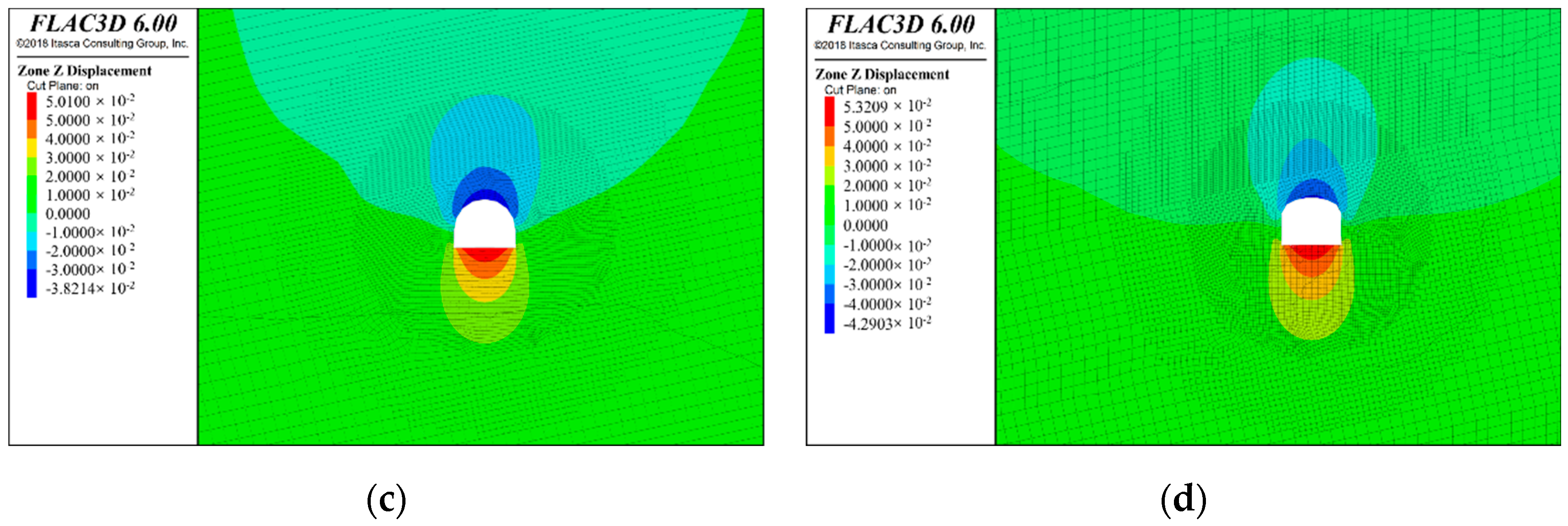
3.3. Influence of Section Shape on Vertical Displacement Cloud Distribution of Surrounding Rock

As shown in Figure 5, vertical displacement mainly occurs on the roof and the floor of the roadway under all four investigated roadway section shapes. When the section is round, the maximum subsidence of the roof is 4.65 cm, and the maximum bulking of the floor is 5.27 cm. When the section is rectangular, the maximum subsidence of the roof is 5.07 cm, and the maximum bulking of the floor is 5.6 cm. When the section is a straight-wall semicircular arch, the maximum subsidence of the roof is 3.82 cm, and the maximum heave of the floor is 5.01 cm. When the section is a three-core arch, the maximum subsidence of the roof is 4.29 cm, and the maximum bulking of the floor is 5.32 cm. The section shape has a minimal influence on the heave of the floor, but the semicircle arch and the three-center arch can effectively reduce the subsidence of the roof.

3.4. Step-by-Step Influence of Section Shape on Horizontal Displacement Cloud Map of Surrounding Rock

As shown in Figure 6 from the perspective of horizontal displacement, the rock surrounding rock a rectangular roadway is significantly more affected by mining than the rock surrounding the other three sections, with the largest horizontal displacement. The maximum deformation of the left and right sides is 4.72 cm and 4.85 cm, respectively. The horizontal deformation of the circular roadway is followed by the displacement of the left and right sides reaching 4.29 cm and 4.37 cm, respectively. The horizontal deformation degree of the rock surrounding the straight-wall semicirular arch roadway is the lowest, and the displacement of left and right sides is 3.47 cm and 3.54 cm, respectively. The horizontal deformation degree of rock surrounding the three-center arched roadway is higher than that of the straight-wall semicircular arch, and the left- and right-side displacement is 4.01 cm and 4.14 cm, respectively, although the deformation degree is lower than that of the circular and rectangular sections.

3.5. Influence of Section Shape on the Morphology of the Surrounding Rock Damage Zone

Figure 7 shows the failure state of the surrounding rock of different roadway sections. The zones in plastic failure state in the simulation are collectively referred to as the damage zone and were separately extracted for display. For the four investigated section shapes, the damage zone of the surrounding rock on both sides presents a trend of more damage than that of the roof and floor. When the section is round, the damage zone of the surrounding rock on the two sides is basically uniform, and the damage zone of the rock surrounding the roof and floor is also uniform. When the section is rectangular, the damage zone of the rock surrounding the roof and floor is uniformly distributed, but the damage zone of the rock surrounding the two sides is arched, and the destructive depth of horizontal surrounding rock on the two sides is the largest. When the sections are a straight-wall semicircular arch and three-core arch, the destructive depth of the rock surrounding the floor considerably greater than that of the rock surrounding the roof, and the damage zone of the rock surrounding the two sides is still arched, but the destructive depth of the rock surrounding the two sides is considerably smaller than that of the rectangular roadway. The straight-wall semicircular arch and the three-center arch sections considerably improve the stability of the rock surrounding the roadway roof.
As shown in Figure 8, the damage area around the tunnel with circular sections is the smallest, and the damage area around the tunnel with rectangular sections is the largest. There is little difference in the damage area around the tunnel between three-center arch and straight-wall semicircle arch, which is larger than that of the circular tunnel and smaller than that of the rectangular tunnel.

3.6. Influence of Section Shape on the Form of the Destructive Danger Area of Surrounding Rock

Rock fractures within the scope of the roadway destruction area grow rapidly, and destruction zone is a key area of support and reinforcement. The neighboring area is a part of the destruction rock. Although it is within range of the elastic state, its mining stress environment is poor, and it is easily affected by external disturbances, which can cause it to enter a state of destruction, becoming a destructive danger for surrounding rock in region. When a bolt or anchor cable support is installed, it is necessary to consider that the anchor end cannot be completely located in the destructive danger area. Otherwise, once the destructive danger area enters the failure state under the influence of external disturbance, the supporting structure will fail, and the reliability of the roadway support will be reduced. In order to characterize the advantages and disadvantages of the stress environment in the rock surrounding the roadway, the mining stress environment coefficient is defined as
η = J 2 I 1
where I1 is the first invariant of the principal stress, and J2 is the second invariant of deviatoric stress and can be expressed as
J 2 = 1 2 ( s 1 2 + s 2 2 + s 3 2 )
I 1 = σ 1 + σ 2 + σ 3
where σ1, σ2 and σ3 are the maximum, intermediate and minimum principal stresses, respectively; S1, S2 and S3 are maximum, intermediate and minimum deviatoric stresses, respectively; σ0, Si and σi (i = 1, 2, 3) are hydrostatic stress, deviatoric stress and principal stress, respectively; and Si=σi – σ0, σ0 = I1/3.
Because the first invariant of principal stress (I1) represents the compression degree of the surrounding rock in three directions, the higher its value, the better the stress environment of the surrounding rock. The second invariant of deviatoric stress (J2) represents the shear degree of surrounding rock, so the higher its value, the worse the stress environment of the surrounding rock. The mining stress environment coefficient is defined as the ratio of the second invariant deviatoric stress to the first principal stress invariants. Owing to rock compressive shear, the greater the value of the mining stress environment coefficient, the more easily the rock mass can be destroyed. The rock shear strength is approximately 10–40% of rock compressive strength, so a scope of mining stress environment coefficient greater than 0.2 is defined as the destructive danger area. The spatial distribution morphology of surrounding rock in the destruction–danger area under different roadway section shapes was extracted in [39]. As shown in Figure 9, the distribution pattern of the shallow destructive danger area is exactly the same as that of the damage zone, indicating that the established destructive danger coefficient can correctly represent the stress environment of the rock surrounding the roadway, and the destructive danger area of the deep surrounding rock is butterfly-shaped. When straight-wall semicircular arch and three-center arch roadway sections are adopted, the destructive danger area in the roof only extends to the siltstone in the upper mudstone, which is considerably smaller than that of the rectangular roadway.
As shown in Figure 10, the destructive danger area around the roadway with circular sections is the smallest, and the destructive danger area around the roadway with rectangular sections is the largest. The destructive danger area of the rock surrounding the three-center arched roadway is slightly larger than that of the straight-wall semicircular arch roadway, and both are larger than that of the circular roadway and smaller than that of the rectangular roadway.

4. Conclusions

In this paper, the advantages and disadvantages of the stress environment of rock surrounding roadways were characterized, and the mining stress environment coefficient was defined as η = J21/2/I1, where I1 is the first invariant of principal stress, and J2 is the second invariant of deviant stress. The greater the mining stress environment coefficient, the greater the larger the stress environment of the surrounding rock. A range of the coefficient greater than 0.2 is defined as the destructive danger area. Comparative analysis of four types of roadway, i.e., round, rectangular, semicirular arch and triple arch, showed that the roadway section shape has an influence on the distribution of mining stress, displacement, damage zone and destructive danger area of the surrounding rock. The stability of rock surrounding the circular roadway was found to be the highest, whereas that of the rectangular roadway was the worst, and that of three-center arch roadway and the straight-wall semicirular arch roadway was higher than that of the rectangular roadway but lower than that of the circular roadway. The destructive danger area of the rock surrounding the circular roadway and the semicircular arch roadway was the smallest; owing to the influence of operating conditions, circular roadways represent an engineering challenge, so the optimal roadway support shape is a semicircular arch. A limitation of the present study is that we only conducted analysis using numerical simulation, and the conclusions were not verified through on-site engineering measurement. In the future, physical tests and field observations will be carried out to verify the conclusions presented herein.

Author Contributions

Conceptualization, T.L. and F.L.; funding acquisition, T.L. and F.L.; supervision, F.L. and Z.L.; writing—original draft, T.L. and Z.L.; writing—review and editing, F.L. and Z.L. All authors have read and agreed to the published version of the manuscript.

Funding

This work is supported by the Natural Science Foundation of Heilongjiang (award number LH2021E104), the Open Fund of the State Key Laboratory of Coal Resources and Safe Mining (Grant No. SKLCRSM21KFA09), Supported by State Key Laboratory of Strata Intelligent Control and Green Mining Co-founded by Shandong Province and the Ministry of Science and Technology, Shandong University of Science and Technology (No. SICGM202203) and the Basic Scientific Research Funds of Heilongjiang Provincial Undergraduate Institutions (Grant No. 2021-KYYWF-1171).

Institutional Review Board Statement

No studies involving humans or animals were undertaken as part of this research.

Informed Consent Statement

Not applicable.

Data Availability Statement

Not applicable.

Conflicts of Interest

The authors declare no conflict of interest.

References

  1. Ma, N.J.; Zhao, X.D.; Zhao, Z.Q. Stability analysis and control of roof in deep mining roadway. J. China Coal Soc. 2015, 40, 2287–2295. [Google Scholar]
  2. Zhang, J.W.; Song, Z.X.; Liu, J.L. Architecture of Structural Regulation Technology for Rock Burst Disaster in Deep Mining of Coal Mine. Coal Sci. Technol. 2022, 50, 27–36. [Google Scholar]
  3. Jing, H.W.; Wu, J.Y.; Yin, Q. Deformation and destructive characteristics of anchorage structure of surrounding rock in deep roadway. Int. J. Min. Sci. Technol. 2020, 30, 17–32. [Google Scholar] [CrossRef]
  4. Wang, W.J.; Yuan, C.; Yu, W.J. Deep large deformation of roadway surrounding rock stability control method research. J. Coal 2016, 9, 2921–2931. [Google Scholar]
  5. Lou, J.F.; Gao, F.Q.; Yang, J.H. Characteristics of evolution of mining-induced stress field in the longwall panel: Insights from physical modeling. Int. J. Coal Sci. Technol. 2021, 8, 938–955. [Google Scholar] [CrossRef]
  6. Wang, J.C.; Fu, Q. Theory and Application of Granular Medium Flow in Top Coal Emission from Fully-mechanized Coal Caving in Low Position. J. China Coal Soc. 2002, 27, 337–340. [Google Scholar]
  7. Ning, S.R.; Su, H.; Gao, J. Research on Automatic Section Precision Forming of Boom-Type Roadheader. In Proceedings of the International Conference on Intelligent Systems Research and Mechatronics Engineering, Zhengzhou, China, 11–13 April 2015; Atlantis Press: Paris, France, 2015; Volume 121, pp. 1250–1256. [Google Scholar]
  8. Wang, J.H. Mechanism and effect analysis of bolt and cable combined support in whole coal roadway. J. China Coal Soc. 2012, 37, 1–7. [Google Scholar]
  9. Yuan, J. Effects of Air Dilution on Hinghly Preheated Air Combustion in a Regenerative Furnace. Energy Fules 1999, 13, 99–104. [Google Scholar] [CrossRef]
  10. Huang, Q.X.; Liu, Y.W. Limit Self-stabilizing Balanced Arch Theory of Roadway Surrounding Rock Support. J. Min. Saf. Eng. 2014, 31, 354–358. [Google Scholar]
  11. Ma, N.J.; Zhao, Z.Q.; Feng, J.C. Supporting Technology of Tunnel Butting Long Bolt under Difficult Condition. Coal Sci. Technol. 2013, 41, 117–121. [Google Scholar]
  12. Kang, H.P.; Jiang, T.M.; Gao, F.Q. Effect of pretensioned stress to rock bolting. J. China Coal Soc. 2007, 32, 2287–2295. [Google Scholar]
  13. He, M.C.; Guo, Z.B. Mechanical Characteristics and Engineering Application of Transversely Resistant Large Deformation Anchor Bolt. Chin. J. Rock Mech. Eng. 2014, 33, 1297–1308. [Google Scholar]
  14. Wang, J.C.; Wang, L.; Guo, Y. Determination of Support Resistance Based on Roof and Coal Wall Control. J. China Coal Soc. 2014, 39, 1619–1624. [Google Scholar]
  15. Wang, J.H. New development of rock bolting technology for coal roadway in China. J. China Coal Soc. 2007, 32, 113–118. [Google Scholar]
  16. Jiang, Y.D.; Zhao, Y.X.; Liu, W.G. Research on floor heave of roadway in deep mining. Chin. J. Rock Mech. Eng. 2004, 23, 2396–2401. [Google Scholar]
  17. Li, G.C.; Zhang, N.; Wang, C.; Zhang, N.-C.; Li, B.-Y. Optimizing the Section Shape of Roadways in High Stress Ground by Numerical Simulation. J. China Univ. Min. Technol. 2010, 39, 652–658. [Google Scholar]
  18. Xie, H.P.; Yu, G.M.; Yang, L. Research on the Fractal Effects of Crack Network in Overlying strata Stratum. China J. Rock Mech. Eng. 1999, 18, 147–151. [Google Scholar]
  19. Wang, Z.G.; Zhou, H.W.; Xie, H.P. Research on Fractal Characterization of Mined Crack Network Evolution in Overlying strata Stratum under Deep Mining. Rock Soil Mech. 2009, 30, 2403–2408. [Google Scholar]
  20. Huang, D.; Tan, Q.; Huang, R.Q. Fractal Characteristics of Fragmentation and Correlation with Energy of Marble under Unloading with High Confining Pressure. China J. Rock Mech. Eng. 2012, 31, 1379–1389. [Google Scholar]
  21. Chen, J.H.; Liu, P.; Liu, L.; Zeng, B.; Zhao, H.; Zhang, C.; Zhang, J.; Li, D. Anchorage performance of a modified cable anchor subjected to different joint opening conditions. Constr. Build. Mater. 2022, 336, 127558. [Google Scholar] [CrossRef]
  22. Chen, J.H.; Zeng, B.Q.; Liu, L.; Tao, K.; Zhao, H.; Zhang, C.; Zhang, J.; Li, D. Investigating the anchorage performance of full-grouted anchor bolts with a modified numerical simulation method. Eng. Fail. Anal. 2022, 141, 106640. [Google Scholar] [CrossRef]
  23. Xu, S.; Gao, L.; Liu, P.Z.; Zhang, P.D.; Liu, P.; Ma, Z.Q.; Kang, X.T. Section shape optimization of gob-side coal-rock roadway in inclined coal seam. Coal Eng. 2022, 54, 122–128. [Google Scholar]
  24. Liu, F.; Gao, M.Z.; Guo, Z.R.; Zhou, C.T.; Wang, J. Study on the propagation mechanism of blast waves using the ultra-dynamic strain test system. Smart Struct. Syst. 2021, 28, 143–152. [Google Scholar]
  25. Huang, B.X.; Zhang, N.; Jing, H.W.; Kan, J.G.; Meng, B.; Li, N. Large deformation theory of rheology and structural instability of the surrounding rock in deep mining roadway. J. China Coal Soc. 2020, 45, 911–926. [Google Scholar]
  26. Wang, J.C.; Liu, F.; Wang, Z.H. Experimental investigation on the movement law of top coal in steeply inclined ultra-thick coal seams. Acta Mech. Sin. 2021, 37, 631–648. [Google Scholar] [CrossRef]
  27. Wang, J.C.; Wang, Z.H.; Tang, Y.S.; Li, M.; Chang, K.L.; Gong, H.; Xu, G.L. Experimental study on mining-induced dynamic load of main roof in deeply buried thick coal seam with weakly consolidated thin bed rock. China J. Rock Mech. Eng. [CrossRef]
  28. Liu, F.; Guo, Z.R.; Lv, H.Y.; Cheng, Z.B. Test and analysis of blast wave in mortar test block. Int. J. Rock Mech. Min. Sci. 2018, 108, 80–85. [Google Scholar] [CrossRef]
  29. Wang, Y.; Song, Z.Y.; Mao, T.Q.; Zhu, C. Macro-Meso Fracture and Instability Behaviors of Hollow-Cylinder Granite Containing Fissures Subjected to Freeze–Thaw–Fatigue Load. Rock Mech. Rock Eng. 2022, 55, 4051–4071. [Google Scholar] [CrossRef]
  30. Si, G.Y.; Durucan, S.; Jamnikar, S.; Lazar, J.; Abraham, K.; Korre, A.; Shi, J.-Q.; Zavšek, S.; Mutke, G.; Lurka, A. Seismic monitoring and analysis of excessive gas emissions in heterogeneous coal seams. Int. J. Coal Geol. 2015, 149, 41–54. [Google Scholar] [CrossRef]
  31. Wang, Y.; Yi, X.; Han, J.; Xia, Y. Acoustic emission and computed tomography investigation on fatigue failure of fissure-contained hollow-cylinder granite: Cavity diameter effect. Fatigue Fract. Eng. Mater. Struct. 2022, 45, 2243–2260. [Google Scholar] [CrossRef]
  32. Cao, W.Z.; Shi, J.Q.; Si, G.Y.; Durucan, S.; Korre, A. Numerical modelling of microseismicity associated with longwall coal mining. Int. J. Coal Geol. 2018, 193, 30–45. [Google Scholar] [CrossRef]
  33. Wang, Y.; Mao, T.; Xia, Y.; Li, X.; Yi, X. Macro-meso fatigue failure of bimrocks with various block content subjected to multistage fatigue triaxial loads. Int. J. Fatigue 2022, 163, 107014. [Google Scholar] [CrossRef]
  34. Qian, M.G.; Xu, J.L.; Wang, J.C. Mining Pressure and Ground Control, 3rd ed.; China University of Mining and Technology Press: Xuzhou, China, 2021. [Google Scholar]
  35. Wang, J.C.; Wang, Z.H.; Yang, S.L. A coupled macro-and meso-mechanical model for heterogeneous coal. Int. J. Rock Mech. Min. Sci. 2017, 94, 64–81. [Google Scholar] [CrossRef]
  36. Hoek, E.; Brown, E.T. Practical estimates of rock mass strength. Int. J. Rock Mech. Min. Sci. 1997, 34, 1165–1186. [Google Scholar] [CrossRef]
  37. Shabanimashcool, M.; Li, C.C. Numerical modelling of longwall mining and stability analysis of the gates in a coal mine. Int. J. Rock Mech. Min. Sci. 2012, 51, 24–34. [Google Scholar] [CrossRef]
  38. Suchowerska, A.M.; Merifield, R.S.; Carter, J.P. Vertical stress changes in multi-seam mining under supercritical longwall panels. Int. J. Rock Mech. Min. Sci. 2013, 61, 306–320. [Google Scholar] [CrossRef]
  39. Li, T.; Gong, H.; Xu, G.L. Study on the influence of in situ stress distribution on the stability of roadway surrounding rock. Adv. Civ. Eng. 2021, 2021, 3570523. [Google Scholar] [CrossRef]
Figure 1. Comprehensive histogram of rock strata.
Minerals 12 01504 g001
Figure 2. Three-dimensional space numerical model of a bottom pumping roadway [39]. (a) Force analysis diagram; (b) numerical model diagram.
Minerals 12 01504 g002
Figure 3. Influence of section shape on the cloud map of maximum principal stress distribution. (a) Circular section; (b) Rectangular section; (c) Semicircular arch section; (d) Three-center arch section.
Minerals 12 01504 g003
Figure 4. Influence of section shape on the cloud map of minimum principal stress distribution. (a) Circular section; (b) Rectangular section; (c) Semicircular arch section; (d) Three-center arch section.
Minerals 12 01504 g004
Figure 5. Influence of section shape on the vertical displacement cloud map of the surrounding rock of a bottom drainage roadway. (a) Circular section; (b) Rectangular section; (c) Semicircular arch section; (d) Three-center arch section.
Minerals 12 01504 g005aMinerals 12 01504 g005b
Figure 6. Influence of section shape on the horizontal displacement cloud map of surrounding rock of a bottom drainage roadway. (a) Circular section; (b) Rectangular section; (c) Semicircular arch section; (d) Three-center arch section.
Minerals 12 01504 g006
Figure 7. Influence of section shape on the damage zone morphology of the rock surrounding a bottom drainage roadway. (a) Circular section; (b) Rectangular section; (c) Semicircular arch section; (d) Three-center arch section.
Minerals 12 01504 g007aMinerals 12 01504 g007b
Figure 8. Influence of section shape on the scope of the damage zone of the rock surrounding a bottom drainage roadway.
Minerals 12 01504 g008
Figure 9. Influence of section shape on destructive danger area form of the rock surrounding a bottom drainage roadway. (a) Circular section; (b) Rectangular section; (c) Semicircular arch section; (d) Three-center arch section.
Minerals 12 01504 g009
Figure 10. Influence of section shape on the scope of the destructive danger area of the rock surrounding a bottom drainage roadway.
Minerals 12 01504 g010
Table 1. Physical and mechanical parameters of rock strata.
Rock ParameterSiltstoneMudstoneGluteniteSandstone
Bulk modulus/GPa1.110.831.00.97
Shear modulus/GPa0.830.380.60.72
Cohesive forces/MPa6.03.04.05.0
Angle of internal friction/°38323438
Angle of dilatancy/°10101010
Tensile strength/MPa2.51.01.52.0
Publisher’s Note: MDPI stays neutral with regard to jurisdictional claims in published maps and institutional affiliations.

