Article

Movement Laws of the Overlying Strata at the Working Face Ends and Their Effects on the Surface Deformation

1
Institute of Geotechnical Engineering, Southeast University, Nanjing 211189, China
2
School of Mines, China University of Mining and Technology, Xuzhou 221116, China
*
Authors to whom correspondence should be addressed.
Minerals 2022, 12(12), 1485; https://doi.org/10.3390/min12121485
Submission received: 18 October 2022 / Revised: 17 November 2022 / Accepted: 22 November 2022 / Published: 23 November 2022
(This article belongs to the Special Issue Green Mining of Coal Mine in China)

Abstract

:
Underground coal mining causes stress relief and strata/ground movement, threatening the safety of the surface structures. Investigating the movement laws of the strata above the working face ends is important because it determines the deformation level of the surface subsidence trough at the boundary, which is also the zone with the largest deformation degree. This paper presents a study on the movement laws of the overlying strata at the working face ends, and assesses their effects on the surface deformation using field monitoring as well as physical and numerical modelling. The results show that the surface deformation at the subsidence trough boundary is closely related to the movement and rotation of the broken blocks of the primary key stratum (PKS), which control the development of the bed separation and the degree of the surface deformation at the corresponding locations. The numerical modelling results suggest that, the larger the mining height, the greater the rotation angle of the broken blocks and the more severe the surface deformation above the ends of the working face. The results also highlight the role of the thickness of the topsoil. The implications of the results and the limitations of the research are also briefly discussed.

1. Introduction

Underground coal extraction inevitably causes stress relief and strata movement, and the mining-out space gradually migrates from the goaf to the surface, forming surface subsidence troughs [1,2]. The shape and magnitude of mining subsidence troughs depend on mining height, mining width, advancement length of working face, coal seam dip angle, strata properties, etc. [3,4,5]. Therefore, the development and formation of surface subsidence are complex, and investigating how mining and geological-related parameters will affect mining subsidence characteristics is of great importance in mining area.
After coal mining, the overlying strata can be divided into three zones according to the degree of movement and damage, namely, falling zone, fracture zone and bending subsidence zone [6]. In shallow coal seam mining with large mining height, it tends to be no bending subsidence zone in the overburden, so the structural characteristics of the primary key stratum (PKS) and its control strata after breakage determine the characteristics of the surface subsidence trough. Recently, surface subsidence caused by shallow coal seam mining has drawn researchers’ attention. For instance, Chen et al. (2019) and Xu et al. (2021) reported case studies on the dynamic characteristics of surface subsidence caused by high-intensity longwall mining in the Shendong coalfield [7,8]. Based on a series of field monitoring results, the authors concluded that the subsidence trough in shallowing coal seam mining with large mining height is characterized by rapid subsidence rate, steep trough edge and stepped subsidence along mining direction. This is because the bending subsidence zone in this mining condition is missing, such that the surface subsidence characteristics are strongly affected by the breakage, rotation, dilation and subsidence of rock strata [9,10,11,12]. For instance, Zhu et al. (2018) and Xu et al. (2020) proposed an accumulative phenomenon of overburden strata expansion induced by mining stress relief [13,14]. Laboratory tests were conducted and a theoretical model was built to investigate how the bulking (in the falling zone) and elastic expansion (in the fracture zone) will affect the bed separation and surface subsidence. On the other hand, Ghabraie et al. (2015, 2017) performed a series of physical models to investigate the characteristics of ground subsidence caused by multi-seam mining [15,16], and part of the results was also supported by the case study reported by Yang et al. (2019) [9].
It is believed that surface subsidence caused by underground coal mining has been a major geological problem in numerous countries [17,18,19,20,21,22,23]. In China, due to the rapid development of coal mining industry, more and more farmlands are disturbed by mining activities, and land reclamation has become an important part in the mining industry [17]. In Indonesia, Sasaoka et al. (2015) reported the characteristics of the surface subsidence caused by underground coal mining under weak geological condition and assessed the impact of the subsidence on underground and surface environments [18]. In Slovenia, a typical coal mine is known as Velenje Coal Mine, with an average angle of dip of 0° and excavation heights of levels from 8.0 to 13.9 m. In situ monitoring of the subsidence factor reached up to 0.86, with an average residual angle of internal friction 23°, which causes a great impact on the natural environment [19]. In Sweden, part of the infrastructures in Kiruna city, including railway, the power station, etc., are severely affected by the large-scale surface subsidence caused by underground caving mining [20]. In India, researchers have reported the formation of sinkhole subsidence due to underground mining activities, and pointed that shallow extraction, weak overburden and geological discontinuities are the main reasons [21]. In Poland, vertical surface displacements in the Upper Silesian Coal Basin were identified using DInSAR technology to achieve quasi-continuous monitoring for large areas of land surface [22]. In Germany, the German State Office for National Measurements observed the residual settlement for closed mine areas and found that settlement is continuously growing after a few decades, causing a potential threat to sensitive objects [23].
One of the tasks faced by mining engineers is to evaluate the likely impact of mining-induced surface subsidence on surface or buried structures [24,25,26,27,28,29,30,31]. It is worth mentioning that curvature and horizontal deformation are the main indicators affecting buildings, and the maximum absolute values of curvature and horizontal deformation are close to the boundary of the subsidence trough, which is the corresponding surface position at the ends of the working face. This means that the edge of the subsidence trough is the area where the surface buildings are most affected. In shallow coal seam mining with large mining height, due to high mining intensity, the mined-out space and degree of rock strata movement and deformation are very large [32,33]. The most significant factors affecting the curvature and horizontal deformation of the edge of the surface subsidence trough are the movement and rotation characteristics of the broken blocks of the overlying PKS at the ends of the working face, including the block size, rotation angle, etc. Therefore, it is of great theoretical significance and engineering guidance value to study the characteristics of strata movement at the end of shallow mining working face with large mining height and its impact on surface deformation. Although some researchers have reported the influence of the strata movement on the surface subsidence formation [34,35], few studies focused on the subsidence trough characteristics at the panel boundary.
Based on a typical shallow coal seam mining case in the Daliuta coal mine, this paper aims to study the movement laws of the overlying strata at the working face ends with large mining height and their effects on the surface deformation using field observation, theoretical analysis, laboratory physical modelling and numerical modelling. The findings of the research may be useful in mining subsidence control and risk assessment with similar geological and mining conditions.

2. Geological Condition and Field Monitoring

Shendong coalfield, one of the eight biggest coalfields worldwide, is the biggest coalfield in China. It is located in the junction area of Inner Mongolia, Shanxi and Shaanxi provinces. The coalfield is covered by drift-sand, with a flat, hilly topography. The geological settings are simple without big faults. Because of the simple geological conditions, numerous coal mines have been constructed, including several coal mines with an annual output of more than 10 million tons. Daliuta mine is one of such coalmines. The longwall 52306, with a 7.0 m mining height and 280.5 m face width, is one of the longwall faces in the No. 3 panel in the Daliuta mine. The average cover depth of the coal seam is around 180 m, with simple geological conditions.
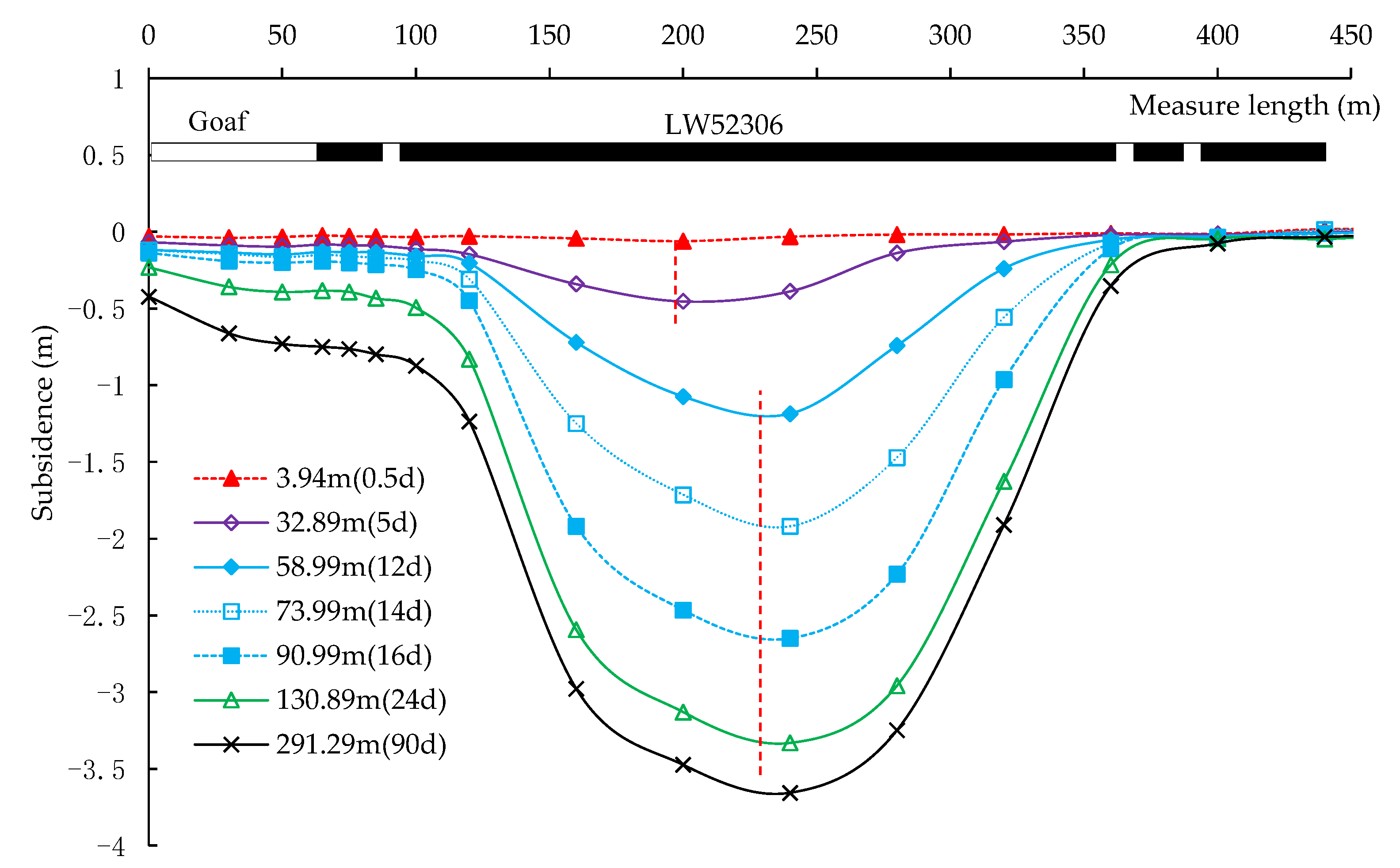
To record the mining subsidence during the extraction of longwall 52306, Xu et al. (2021) [7] employed three survey lines above the longwall panel, as shown in Figure 1. Further details can be found in Xu et al. (2021) [7], and parts of results are presented in Figure 2. Two main conclusions are highlighted. First, due to the instability of the boundary coal pillar, surface subsidence above the coal pillar is considerably greater than that at the other side. Second, because of the asymmetric boundary condition of the longwall panel, transverse surface subsidence trough is also not symmetric. At the initial stage, surface subsidence near the goaf side (left side in Figure 2) initiated earlier than the other side. Consequently, the maximum subsidence position was closer to the left side (see the subsidence trough when the working face passed 32.89 m behind the survey line). With the advancement of the working face, the maximum subsidence point gradually moved to the center of the panel.
To compare the subsidence amount and rate between the middle (line A) and the boundary (line B) of the working face, Figure 3 presents the subsidence value and ratio of lines A and B along the distance to the longwall face. Results show that the middle of the working face settled considerably larger than the boundary. Furthermore, subsidence in the middle of the working face also initiated earlier than the boundary of the working face (see Figure 3b).
Interestingly, the existence of the boundary coal pillar also affects the surface deformation degree. As shown in Figure 2, although the left side of the working face settled more than the right side, the surface deformation level tends to be smaller than the right side. Table 1 summarizes the surface deformation parameters at the left and right sides of the working face. Results show that all the deformation parameters at the left side are smaller than these of the right side. Lower surface deformation degree indicates a smaller influence of the subsidence on the surface structures. As discussed before, for shallow coal seam mining with large mining height, the surface subsidence characteristics are determined by the movement and rotation of the strata. Therefore, it is important to investigate the movement law of the overlying strata at the corresponding position.

3. Physical Model

3.1. Model Preparation

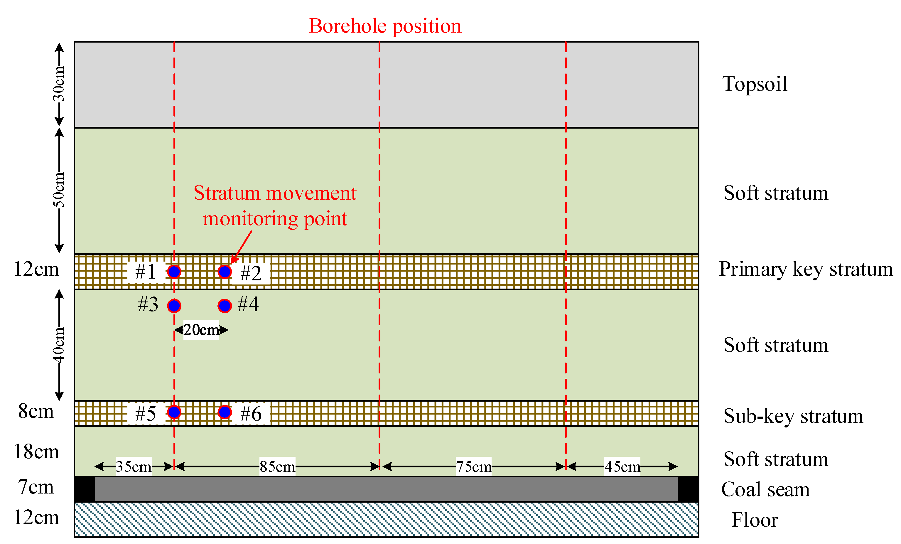
A laboratory physical modelling study was used to investigate the movement law of the overlying strata at the working face ends. According to the occurrence characteristics of the overlying strata of longwall 52306 panel, and to qualitatively reveal the breakage and movement laws of the rock strata at the ends of the working face, the overlying strata are simplified into two key strata, namely, the sub key stratum (SKS) and the primary key stratum (PKS). The purpose of the simplification is to highlight the key strata, especially the main control role of the PKS. The occurrence characteristics materials of the strata in the model are shown in Table 2. From the bottom to the top, the model consists of a 12 cm thick floor, a 7 cm thick coal seam, an 18 cm thick soft rock stratum, an 8 cm thick SKS, a 40 cm thick soft rock stratum, a 12 cm thick PKS, a 50 cm thick soft rock stratum and a 30 cm thick topsoil. The thickness of the model is 20 cm. Note that the floor, coal seam, SKS and PKS were prepared one-time (one layer), while the soft rock strata and topsoil were prepared in several layers, with each sub-layer of 2–3 cm thick.
In the physical model, river sand was used as aggregate and calcium carbonate and gypsum were used as cement. The mixed ratio of the materials was calculated according to the rock mechanical parameters measured in the laboratory, as shown in Table 2. First, the materials were mixed according to the proportion, followed by adding the water. Then, these materials were mixed evenly. Next, the mixture was laid evenly on the model frame. To simulate the layers between the strata in the coal measure strata, mica powder was used to fill the gap between the strata. During the preparation of the model, the baffles were used to restrict the model in the lateral direction. After the model preparation, it was placed for 7–10 days to fully shape. Then, the baffles were removed step by step to further dry the model, until the model was dried completely.
Figure 4 shows the physical model structure and the arrangement of strata movement observation boreholes and displacement monitoring points. In the model, three strata movement observation boreholes were arranged in the model, the boreholes on the left and right sides are 35 cm and 45 cm away from the mining boundary, respectively, and the middle boreholes are in the center of the model.
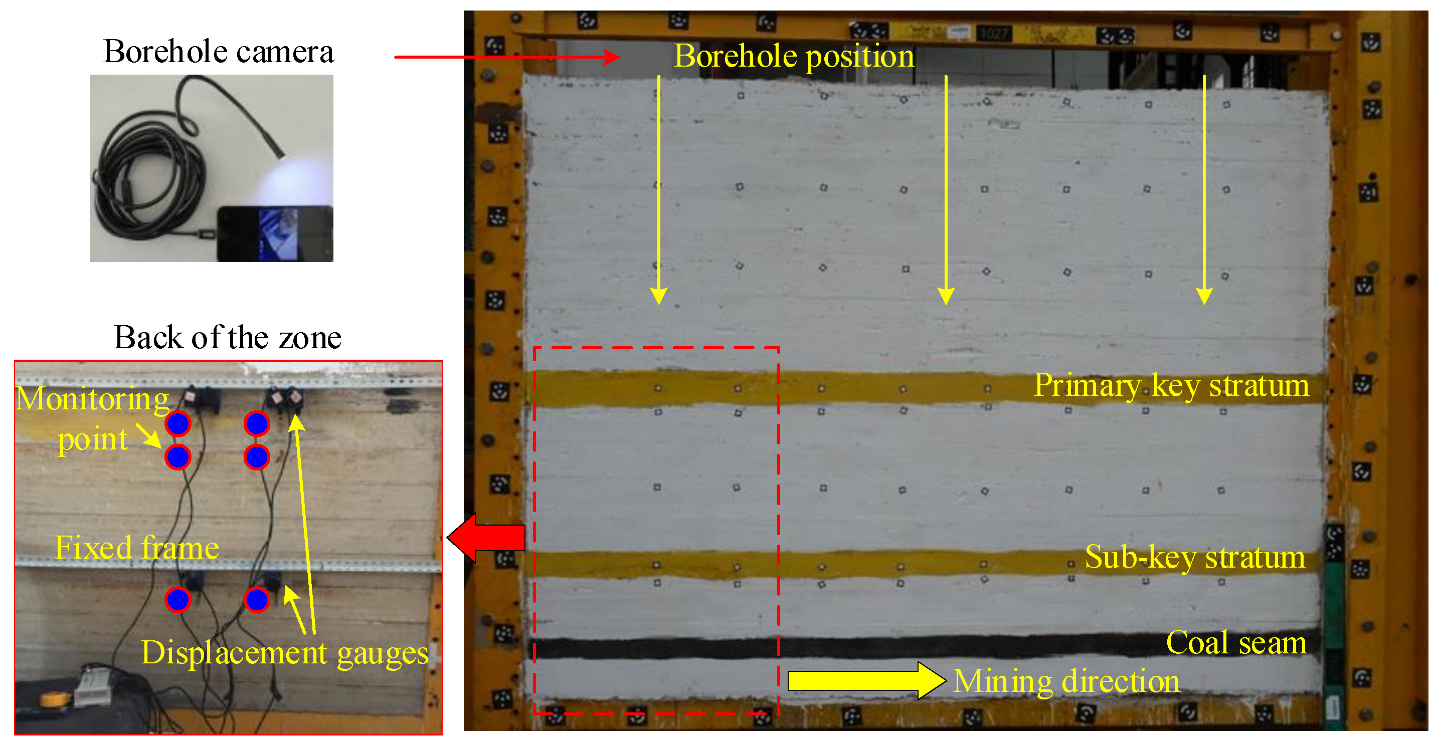
In order to capture the dynamic movement characteristics of the strata during the mining process, the instantaneous displacement high-speed acquisition instrument (along with the displacement sensors) was installed at the first observation borehole location, as well as 20 cm from the first borehole position, as shown in Figure 4 and Figure 5. When the rock strata move, the recorder can record the length of the rope pulled out, and then record the subsidence of the rock strata at the fixed point. The acquisition frequency of the high-speed acquisition instrument is five times per second, so it can completely record the law of rock strata breaking movement during mining. Figure 4 and Figure 5 show that measuring points 1 and 2 are located on the PKS, measuring points 3 and 4 are located on the top of the soft rock strata controlled by the SKS, and measuring points 5 and 6 are located on the SKS. The rotation angle of the broken block can be calculated based on the subsidence data of two measuring points, while the bed separation under the PKS can be calculated by the difference of the subsidence of two points on the same vertical direction (i.e., measuring points 1 and 3, or measuring points 2 and 4).
Figure 5 also shows the micro borehole camera system used in the physical model test. It can be lowered from the top of the borehole of the model to observe the fracture and dislocation of the rock strata affected by coal mining, and monitor the dynamic process of the generation and closure of the bed separation. After the installation of the monitoring equipment, a 5 cm wide coal pillar at the boundary was reserved and then the 20 cm wide cut hole was opened, as shown in Figure 5. Thereafter, the mining process was simulated by removing the coal seam with a length of 5 cm. During this period, the breakage and movement of the rock strata were carefully observed using monitoring sensors and devices.

3.2. Results

3.2.1. Breakage of the Immediate Roof and SKS

As the immediate roof was relatively hard, the immediate roof started falling when the total advancement length of the working face reached 50 cm, as shown in Figure 6a. The collapse height of the immediate roof is 18 cm, meaning that it fell directly to the bottom of the SKS. Consequently, a large bed separation was generated below the SKS.
With the continuous advancement of the working face, the immediate roof continued to collapse, and the overhanging length of the SKS gradually increased. When the working face continued to advance 55 cm, the SKS broke, with a breaking step of 45 cm, as shown in Figure 6b. The breakage of the SKS also caused the synchronous breakage of the soft rock strata that the SKS controlled. The mined-out space was gradually transferred to the bottom of the PKS. This demonstrates the control effect of the SKS to the overlying soft rock strata. It is also found that the rock strata breaking angle at the cut hole side is smaller than that at the working face side.
After the breakage of the SKS, considerable strata movement and rotation were observed. The instantaneous displacement sensors recorded the whole movement process of the SKS and the soft strata, as shown in Figure 7a. Because measuring point 3 is located at the fracture line of the rock strata, the fixed point fell off when the rock strata broke. Therefore, measuring point 3 did not record any data. Also note that the subsidence of the PKS was neglectable during this stage.
Figure 7a shows that measuring points 5 and 6 settled synchronously at the same time, and the settling speed was very fast. Two measuring points settled sharply to the maximum value within one second and remained stable. The final subsidence of measuring point 5 is 18.36 mm, and that of measuring point 6 is 39.07 mm. Results show that although both measuring points are located on the SKS, their subsidence values differ greatly due to the rotation effect of the broken block. According to the differential subsidence of measuring points 5 and 6, and their distance, the rotation angle of the broken block can be calculated as 4.63°.
Figure 7b shows the subsidence data of measuring point 4. Because the rock strata broke from the bottom to the top, the subsidence of measuring point 4 initiated slightly later than that of the SKS. Similar to measuring points 5 and 6, the subsidence of measuring point 4 also changed rapidly, reaching the maximum subsidence of 14.03 mm in a short time. The final subsidence of point 4 is less than that of measuring point 6 directly below it, indicating that the mined-out space was not completely transferred to the bottom of the PKS, and part of the spaces were evenly distributed among the soft rock strata.

3.2.2. Breakage of the PKS

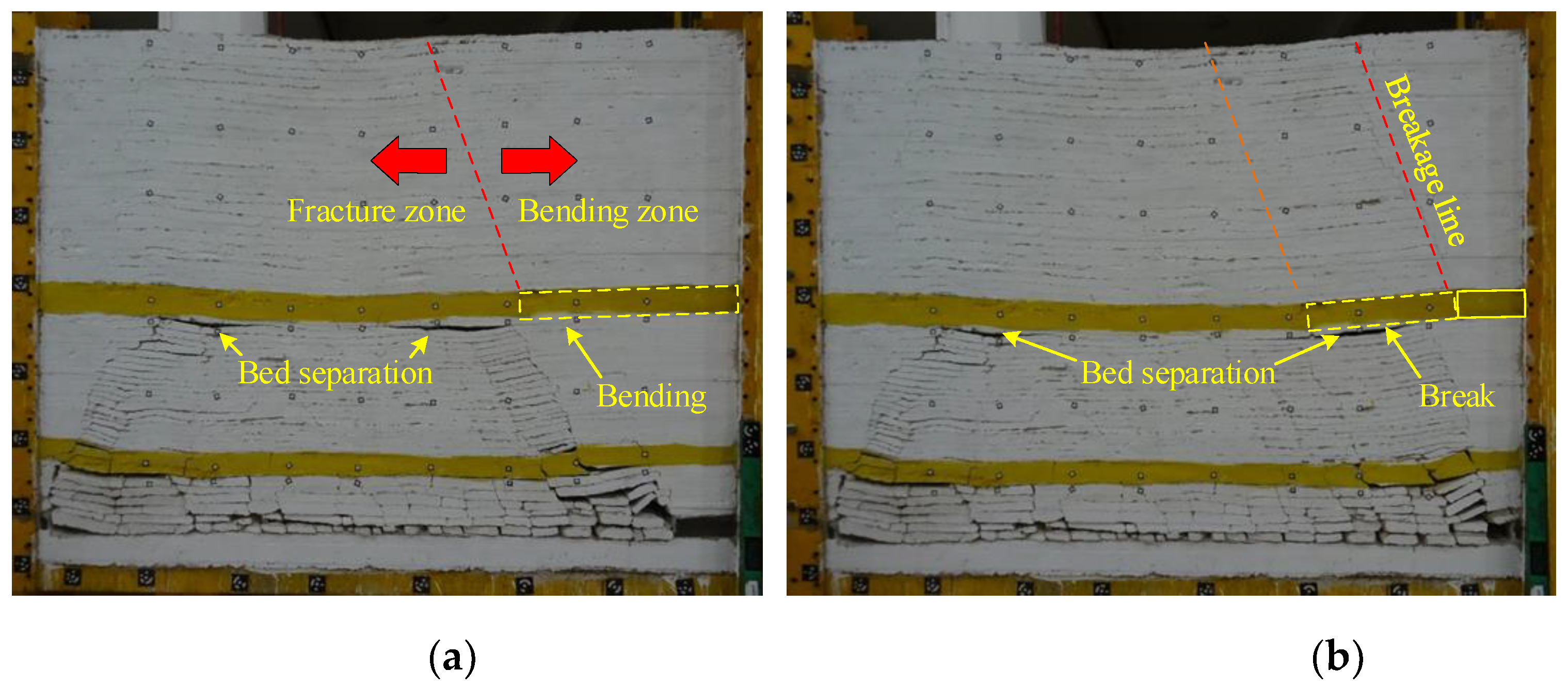
With the further advancement of the working face, the SKS periodically broke and the overhanging length of the PKS gradually increased. When the SKS broke again, cracks were observed in the middle of the suspended part of the PKS. Subsequently, the PKS completely broke, rotated and subsided, as shown in Figure 8a. After the breakage of the PKS, the bed separation space was transferred to the surface, and only part of the separation space was reserved at both ends. Similarly, the breaking angle of the rock strata at the side of the working face was still greater than that at the cut hole.
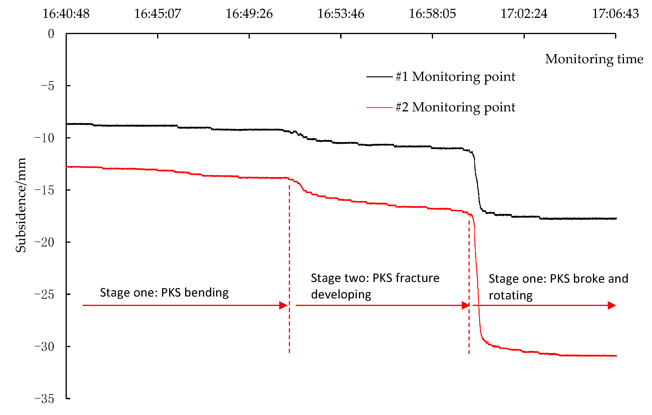
Figure 9 shows the data of measuring points 1 and 2 during the deformation and movement of the PKS. Results show that the subsidence law of the PKS in the physical model is mainly divided into three stages, namely, the bending stage, the fracture development stage and the breakage and rotation stage. Therefore, a similar simulation experiment can well simulate the breaking process of the PKS in actual mining. During the whole deformation and breaking process, the final subsidence of measuring point 1 was 9.22 mm, and that of measuring point 2 was 18.47 mm. Therefore, the rotation angle of the block formed after the breakage of the PKS is 2.1°.
The subsidence data of the PKS in different stages mentioned above are summarized in Table 3. Table 3 shows that, during the whole deformation and fracture period of the PKS, the deformation of the PKS in the bending stage accounts for about 10% of the total subsidence, while the deformation of the PKS in the fracture development stage accounts for about 16%. However, the subsidence in the breakage and rotation stage of the PKS accounts for about 74% of the total subsidence. Therefore, the main subsidence stage of the PKS in the mining process is the rotary movement of the broken blocks.
When the working face was further advanced, the SKS further broke periodically. As shown in Figure 8b, at this time, the overhanging length of the PKS further increased, such that the periodic breaking occurred when the overhanging distance exceeded the limited value. It is worth noting that when the PKS broke periodically, the overlying soft rock strata broke synchronously, and the fracture zone of the rock strata was rapidly transferred to the front, and the surface significantly subsided. This proves that the breakage of PKS plays a major role in controlling the soft strata breakage surface deformation.

3.2.3. Monitoring Results of the Borehole Cameras

Figure 10 shows the four types of deformation and dislocation of the borehole captured by the borehole camera during the mining process in the physical model. Note that these phenomena were observed in multiple locations.
The internal characteristics of the borehole are closely related to the deformation and fracture laws of the rock strata, which are mainly affected by the coal seam mining disturbance. Therefore, the boreholes at different locations exhibit different deformation and dislocation laws, as described below:
(1) When the borehole is located at the mining boundary (working face end or cut hole), the borehole wall is smooth before mining, as shown in Figure 10a. With the gradual advancement of the working face, the overlying strata break layer by layer. As a result of the rotation of the rock strata breaking block, the borehole wall shows stepped dislocation, as shown in Figure 10b and Figure 11a. However, after the overlying strata at the mining boundary break, there is only unidirectional rotary movement, so the final state of the borehole at the mining boundary is as shown in Figure 10b.
(2) If the drill hole is in the middle of the working face, when the rock strata near the drill hole break for the first time, the borehole wall shows stepped dislocation. However, as the working face continues to advance, the rock strata break periodically, and the broken blocks will reversely rotate, causing the dislocation of the internal surface of the borehole to gradually reduce or even recover to its initial state.
(3) Specifically, the borehole may be blocked as shown in Figure 10d. There are two main reasons. First, the borehole is located at the mining boundary, and the turning angle of the broken block is too large. Second, the borehole is close to the collapse zone, and the surrounding rock strata break seriously, so the borehole is completely damaged after mining. Nevertheless, the deformation and dislocation of the borehole due to longwall mining are complex. Care should be taken when applying these conclusions.

3.2.4. Mining-Induced Fractures and Surface Subsidence

To further investigate the development of the bed separation and fractures/fissures, Figure 12 illustrates the sketch of the fissures after the extraction of the coal seam.
To qualitatively explain the problem, the influence of the mining direction on the rock strata movement and fracture development is ignored. The movement pattern of the strata after coal mining in Figure 12 can be regarded as the simulation result of the inclined section of the working face. Therefore, the two ends of the model can be regarded as the end of the working face, and the broken blocks of the KS can be regarded as the “arc-shaped triangle block” formed after the overlying rock breaking in the form of slab in actual mining. Figure 12 also shows that a 1.5 cm height bed separation space was reserved at both ends of the working face after mining. According to the similarity ratio, 1.5 cm corresponds to 1.5 m height bed separation space in the actual mining below the broken blocks of the PKS above the ends of the working face.
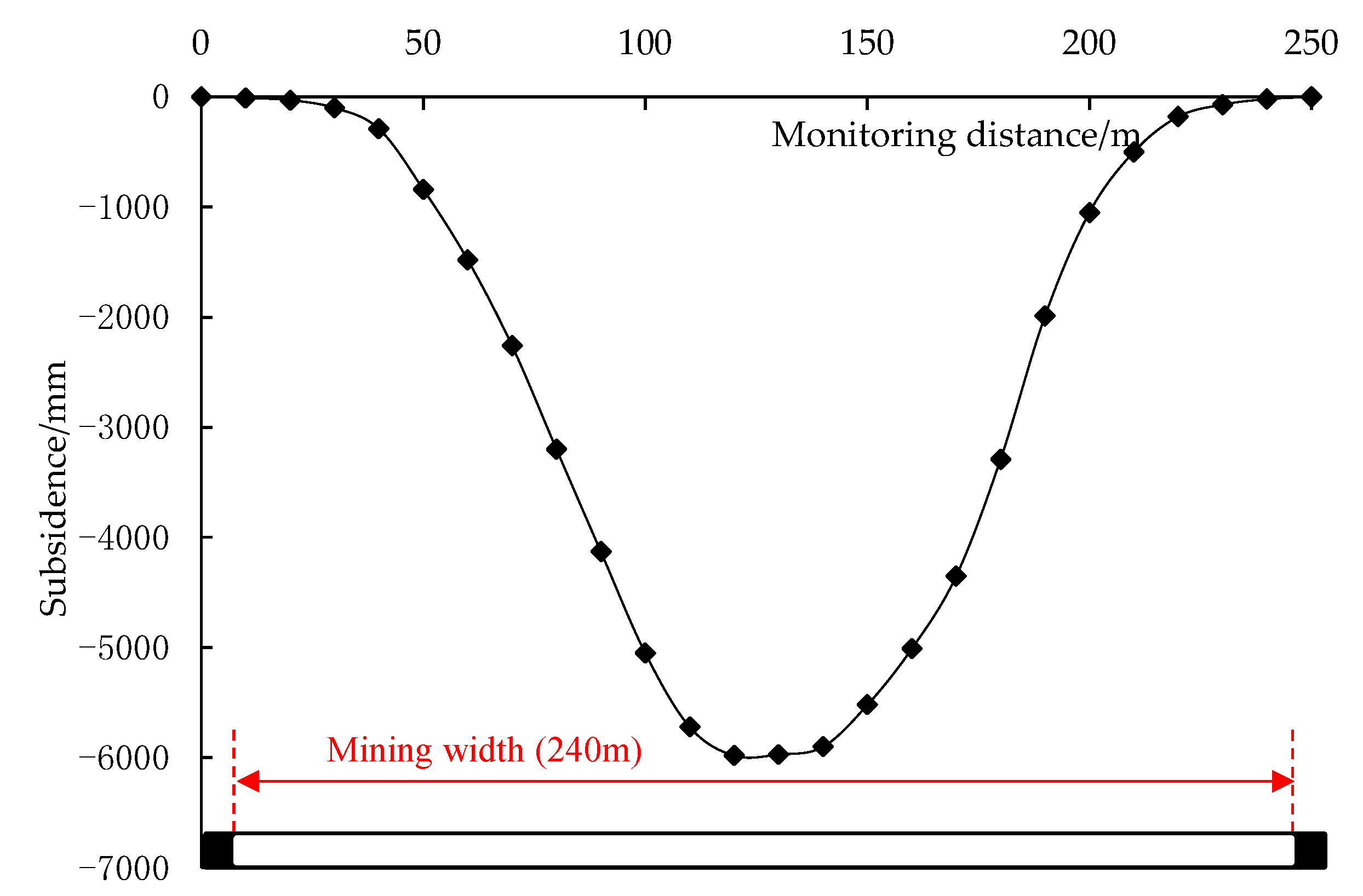
Finally, surface subsidence caused by the longwall coal mining is obtained using image analysis technology, as shown in Figure 13.
Figure 13 shows that the flat bottom is observed in the surface subsidence curve, indicating that the mining degree of the coal seam has reached the critical mining width. In the physical model, the mining thickness of the coal seam is 7 m, and the maximum surface subsidence is 5.98 m; therefore, the subsidence coefficient can be calculated as 85.4%. Obviously, this value is much greater than the subsidence coefficient (53%) obtained from field measurement. Numerous field measurement results show that the subsidence coefficient due to the first layer coal seam mining in the Shendong mining area is between 50% and 60% [7,21]. This is because it is difficult to simulate the crushing expansion characteristics of the immediate roof in a similar simulation, so the subsidence coefficient is considerably larger.

4. Numerical Modelling

4.1. Model Setup and Modelling Plan

To qualitatively study the influence of the rotation angle of the broken blocks at the ends of the working face on the surface deformation, numerical models performed in UDEC (Version 6.00, Itasca Consulting Group, Inc., Minneapolis, MN, USA) were performed. By controlling the mining height of the working face, the rotation angle of the broken blocks can be controlled. Then, the influence of the rotation angle of the broken blocks on the surface deformation is studied. In addition, the field measurement results also show that the thickness of topsoil also has a great effect on the surface deformation. This is because topsoil can buffer and homogenize the rotation of the broken blocks at the end of the working face. Therefore, the influence of the thickness of the topsoil on the surface deformation is also studied. Consequently, by referring to the geological condition of longwall 52306 panel of the Daliuta coal mine, the width of the working face is determined to be 250 m, with two layers of KS, and two working faces are designed in the model. By changing mining height and the thickness of the topsoil, the final modelling plan is summarized in Table 4.
Table 4 shows that nine models were established, of which models 1–5 are used to study the influence of mining height on the strata movement and surface deformation, and models 4 and 6–9 are used to study the influence of topsoil thickness on surface deformation. The occurrence characteristics, rock mechanics and joint mechanics parameters of each rock stratum in the model are shown in Table 5 (taking model 4 as an example). These parameters are determined based on the laboratory tests on the coal/rock samples drilled from the field.
The model configuration is also depicted in Figure 14. As shown in Figure 14 and Table 5, the thickness of the immediate roof, SKS and PKS are 15 m, 10 m and 20 m, respectively. The material constitutive model is elastic-plastic, which conforms to the Mohr Coulomb criterion. The bottom of the model is vertically restricted and the two sides are horizontally restricted.
In the simulation process, the coal seam in working face 1 was extracted at one time, followed by the extraction of the coal seam in working face 2. In this way, the simulation results can be regarded as the section that is parallel to the working face, instead of section following the mining direction. During excavation, displacement measuring points were arranged in the KSs and the soft rock beneath them, as shown in Figure 14.

4.2. Numerical Model Results

4.2.1. The Effect of Mining Height

Figure 15 shows the strata movement characteristics and mining induced bed separation development in two models (mining height 4 m and 7 m).
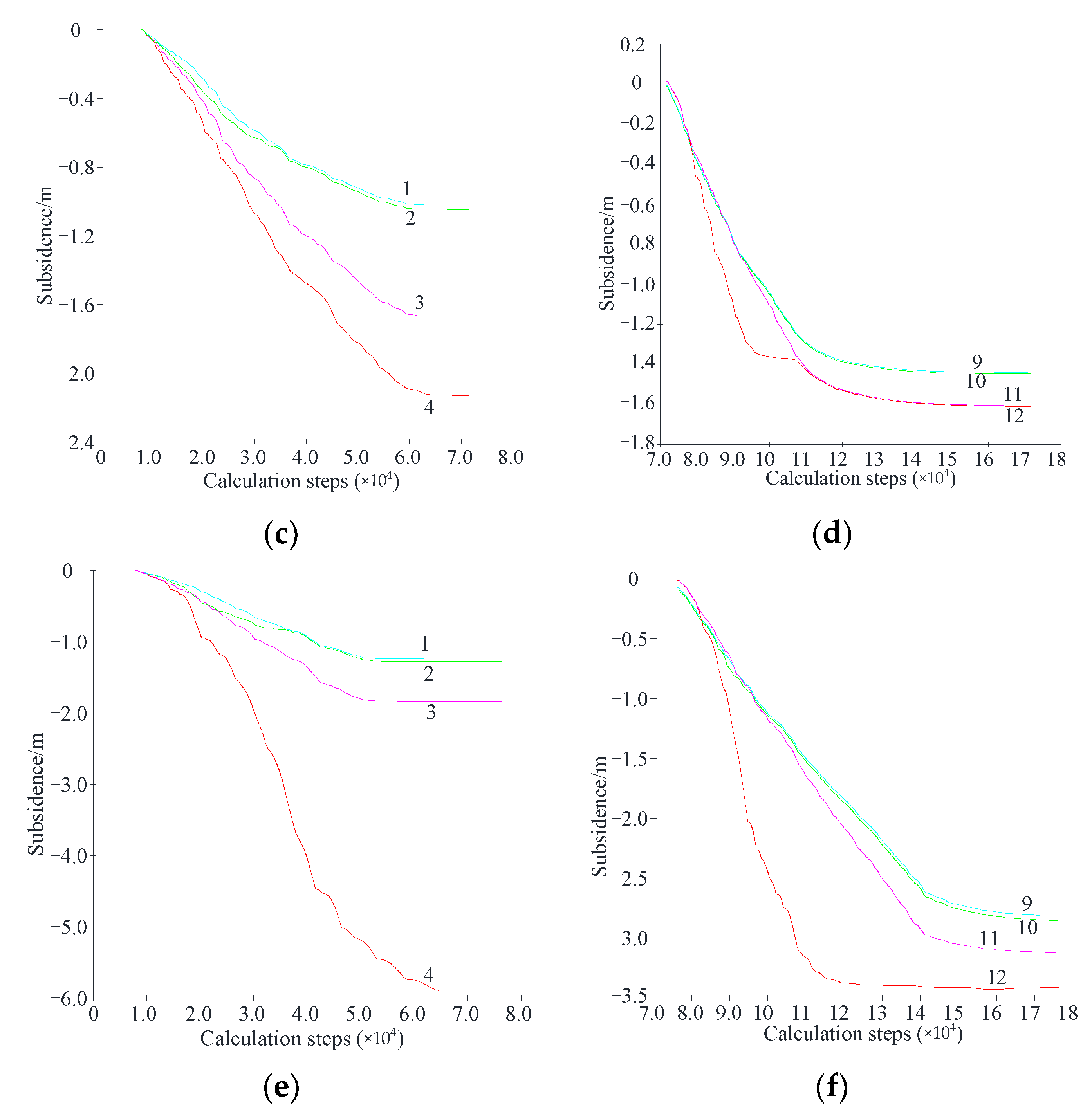
Figure 15 shows that, after coal mining, the bed separation mainly exists above the end of the working face. When the mining height increases from 4 m to 7 m, the height of the bed separation under the PKS and the rotation angle of the broken blocks of the PKS also increase. This increases the degree of the surface deformation, as discussed later. To further investigate the movement laws of the strata and their effects on the surface deformation, Figure 16 presents the strata subsidence of working faces No. 1 and 2 in the models with mining height of 4 m, 6 m and 8 m.
Figure 16 shows that, regarding the mining height, the movement laws of the strata at the working face ends are entirely different. For instance, in the model with 8 m mining height, when mining working face No. 1, measuring points 1 and 2 show similar but very small subsidence values (because they were located at the panel boundary), measuring points 3 and 4 display significantly different subsidence value, indicating that a great bed separation space (4.0 m) formed beneath the PKS. On the other hand, when mining the second working face, the subsidence of the broken block at the left end increased due to the large compression deformation of the section coal pillar between the working faces. However, it is worth noting that the subsidence of the blocks at the right end is much smaller than that in the first working face (compare points 4 and 12 in Figure 16). Consequently, the difference between the subsidence at both ends of the block is smaller in the second working face, so the rotation angle of the broken block is also smaller. This leads to the corresponding reduction of the separation space beneath the PKS.
In general, the larger the mining height, the greater the subsidence of the broken blocks of the PKS. For instance, when the mining height is 4 m, the subsidence value is 1.2 m; when the mining height increases to 8 m, the subsidence value increases to 1.9 m. Consequently, an increasing trend is also observed for the size of the bed separation space beneath the PKS, as shown in Figure 16.
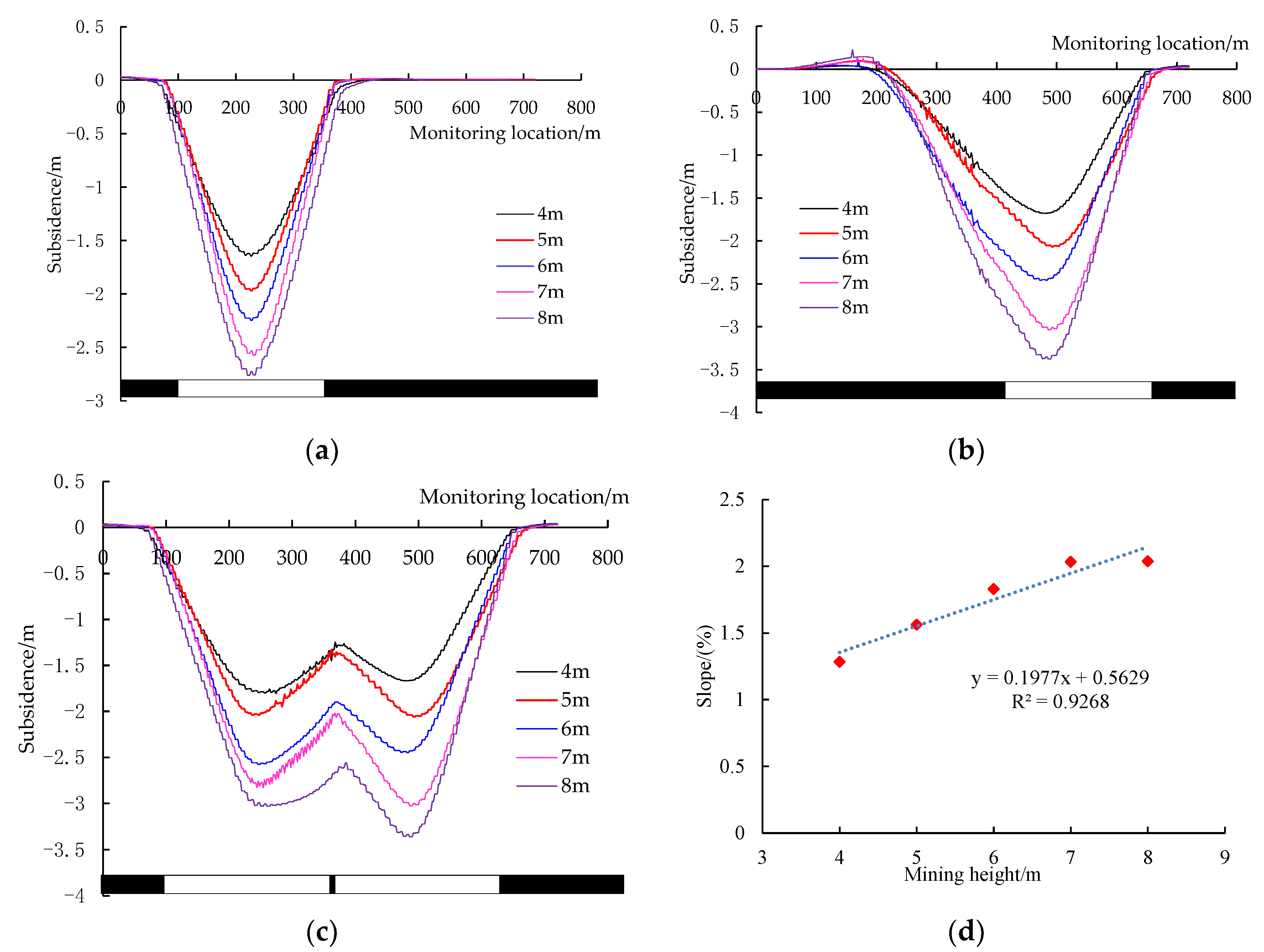
To investigate the rotation and subsidence of the broken blocks of the PKS on the surface deformation, see Figure 17.
Figure 17a shows that, when mining the first working face, with the increase of mining height, the maximum surface subsidence increases from 1.55 m to 2.75 m. Interestingly, the surface subsidence caused by mining the second working face is slightly greater than that of the first working face, with the mining subsidence between 1.60 m and 3.37 m, as shown in Figure 17b. However, it should be noted that the scope of surface subsidence trough caused by mining the second working face is also larger than that of the first working face, especially at the side of section coal pillar. This result is consistent with the field measurement results presented in Figure 2.
To investigate the effect of mining height on the surface deformation, Figure 17d presents slope value with mining height in the first working face. Results show that with the increase of the mining height, the slope of the surface subsidence trough tends to increase linearly. When the mining height is 4 m, the maximum slope is 1.28%, while when the mining height of the working face increases to 8 m, the maximum slope increases to 2.04%. The fitting formula of the relationship between the slope and the mining height is presented in Figure 17d. R2 = 0.9268 indicates a good fit for the data.

4.2.2. The Effect of the Thickness of Topsoil

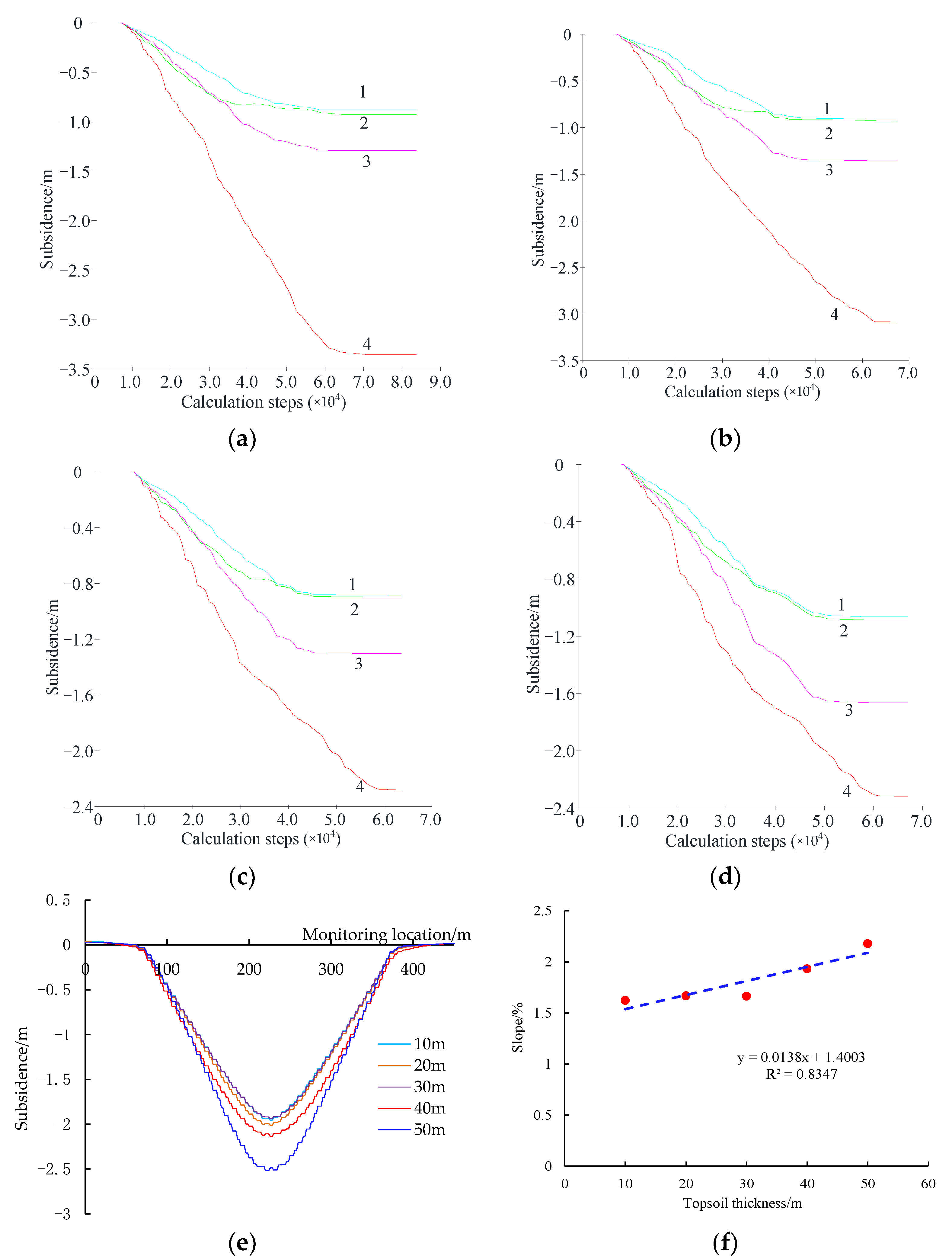
Figure 18 presents the strata movement and surface subsidence due to mining below different thickness of topsoil.
It can be seen from Figure 18a–d that the thicker the loose layer, the greater the subsidence of measuring point 3, which corresponds to the subsidence of the broken blocks of PKS. When the thickness of the topsoil increases from 10 m to 50 m, the subsidence of measuring point 3 increases from 1.25 m to 1.60 m. Figure 18e presents the surface subsidence caused by mining with different thickness of the topsoil. Results show that the greater the topsoil thickness, the larger the surface subsidence. This is due to the fact that, although the topsoil can “homogenize” the surface subsidence, the increase of the thickness of the topsoil also results in a larger geostatic stress imposing on the PKS. Therefore, the total subsidence of the PKS also increases, resulting in a larger surface subsidence. Similarly, with the increase of the thickness of the topsoil, the slope of the surface subsidence trough also tends to increase linearly. When the topsoil thickness increases from 10 m to 50 m, the maximum slope increases from 1.66% to 2.24%. The fitting formula of the relationship between the slope and the mining height is presented in Figure 18f.

5. Discussion and Conclusions

When the roof is managed by the total caving method, underground coal mining will lead to a series of mining damage problems, such as underground dynamic disasters, water and coalbed methane resources destruction, and surface subsidence. These mining damage problems are more prominent in typical high-intensity mining areas, and all of these are related to the movement law of rock strata and mining fractures. For example, the problem of roof disaster is mainly related to the form and stability of the strata broken structures. The fractures of the strata due to mining provide the main channel for the flow of water and gas. The surface subsidence is the final characterization of the strata movement transferred to the surface. Conversely, if we can reveal the law of rock strata movement, we can not only reduce roof disasters, control water and gas outburst, and mitigate mining surface subsidence and other mining damage problems, but also make better use of mining rock fractures to maximize the mining and utilization of coal and coal measures associated resources, such as the extraction of coalbed methane, the establishment of underground reservoirs, etc. The movement of rock strata due to mining causes many mining damage problems. Therefore, revealing the law of rock strata movement is also an important basis for using mining fractures to reduce and control these mining damage. Furthermore, after coal mining, surface deformation above the ends of the working face (the panel boundary) tends to be largest, causing a great impact on the surface structures. Therefore, investigating the movement laws of the overlying strata at the ends of the working face and their effects on surface deformation are crucial in mitigating mining induced damage to the environment.
To overcome the issue mentioned above, the field monitoring and physical and numerical model results are presented to study the movement laws of the overlying strata at the working face ends, and to assess their effects on the surface deformation. The work done in this paper focuses on high-intensity longwall mining (large mining height and wide working face). The following main conclusions can be draw from the work:
(1) Field monitoring results show that the transverse surface subsidence trough is not symmetric due to the instability of the boundary coal pillar, causing the dynamic movement of the maximum subsidence point. Subsidence in the middle of the working face initiated earlier than the boundary of the working face, and deformation parameters at the left side (boundary coal pillar instability) are smaller than these of the right side, indicating a smaller influence of the subsidence on the surface structures.
(2) Results from the physical model show that the surface deformation at the subsidence trough boundary is closely related to the movement and rotation of the broken blocks of the PKS, which control the development of the bed separation and the degree of the surface deformation at the corresponding locations. The main subsidence stage of the PKS in the mining process is the rotary movement of the broken blocks (accounting for 74% of the total subsidence in the physical model).
(3) The internal characteristics of the borehole after mining are closely related to the deformation and fracture laws of the rock strata, which are mainly affected by the coal seam mining disturbance. Based on the physical modeling results, three types of borehole deformation are classified, namely, dislocation, recovery and blocking.
(4) The numerical model results suggest that the larger the mining height, the greater the rotation angle of the broken blocks and the more severe the surface deformation above the ends of the working face. The results also highlight the role of the thickness of the topsoil.
Finally, note that the study presented in this paper only focuses on limited mining and geological conditions. Additional work is needed to further investigate the laws of the strata movement at the working face ends and reveal the fundamental mechanism of the strata movement on the surface deformation at the panel boundary.

Author Contributions

Conceptualization, investigation and modelling, J.X. and P.J.; writing, review and editing, J.X.; supervision and project administration, W.Z.; funding acquisition, W.Z. All authors have read and agreed to the published version of the manuscript.

Funding

This research was funded by National Natural Science Foundation of China, grant number: 52074265.

Data Availability Statement

Some or all data, models or code that support the findings of this study are available from the corresponding author upon reasonable request.

Conflicts of Interest

The authors declare no conflict of interest.

References

  1. Kratzsch, H. Mining Subsidence Engineering; Springer Science & Business Media: Berlin/Heidelberg, Germany, 2012. [Google Scholar]
  2. Dunrud, C.R. Coal mine subsidence—Western United States. Rev. Eng. Geol. 1984, 1, 151–194. [Google Scholar]
  3. Han, H.; Xu, J.; Wang, X.; Xie, J.; Xing, Y. Surface Subsidence Prediction Method for Coal Mines with Ultrathick and Hard Stratum. Adv. Civ. Eng. 2019, 2019, 3714381. [Google Scholar] [CrossRef]
  4. Oh, H.-J.; Lee, S. Integration of ground subsidence hazard maps of abandoned coal mines in Samcheok, Korea. Int. J. Coal Geol. 2011, 86, 58–72. [Google Scholar] [CrossRef]
  5. Jing, Z.; Wang, J.; Zhu, Y.; Feng, Y. Effects of land subsidence resulted from coal mining on soil nutrient distributions in a loess area of China. J. Clean. Prod. 2018, 177, 350–361. [Google Scholar] [CrossRef]
  6. Qian, M.G.; Shi, P.W.; Xu, J.L. Mining Pressure and Strata Control; China University of Mining and Technology Press: Xuzhou, China, 2003; pp. 188–190. [Google Scholar]
  7. Xu, J.; Zhu, W.; Xu, J.; Wu, J.; Li, Y. High-intensity longwall mining-induced ground subsidence in Shendong coalfield, China. Int. J. Rock Mech. Min. Sci. 2021, 141, 104730. [Google Scholar] [CrossRef]
  8. Yang, X.; Wen, G.; Dai, L.; Sun, H.; Li, X. Ground Subsidence and Surface Cracks Evolution from Shallow-Buried Close-Distance Multi-seam Mining: A Case Study in Bulianta Coal Mine. Rock Mech. Rock Eng. 2019, 52, 2835–2852. [Google Scholar] [CrossRef]
  9. Wu, Z.; Xia, T.; Nie, J.; Cui, F. The shallow strata structure and soil water content in a coal mining subsidence area detected by GPR and borehole data. Environ. Earth Sci. 2020, 79, 500. [Google Scholar] [CrossRef]
  10. Zhang, X.; Yu, H.; Dong, J.; Liu, S.; Huang, Z.; Wang, J.; Wong, H. A physical and numerical model-based research on the subsidence features of overlying strata caused by coal mining in Henan, China. Environ. Earth Sci. 2017, 76, 705. [Google Scholar] [CrossRef]
  11. Cao, J.; Huang, Q.; Guo, L. Subsidence prediction of overburden strata and ground surface in shallow coal seam mining. Sci. Rep. 2021, 11, 18972. [Google Scholar] [CrossRef] [PubMed]
  12. Zhu, W.; Yu, S.; Xu, J. Influence of the elastic dilatation of mining-induced unloading rock mass on the development of bed Separation. Energies 2018, 11, 785. [Google Scholar] [CrossRef] [Green Version]
  13. Xu, J.L.; Qin, W.; Xuan, D.Y.; Zhu, W.B. Accumulative effect of overburden strata expansion induced by stress relief. J. China Coal Soc. 2020, 45, 35–43. [Google Scholar]
  14. Ghabraie, B.; Ren, G.; Smith, J.V. Characterising the multi-seam subsidence due to varying mining configuration, insights from physical modelling. Int. J. Rock Mech. Min. Sci. 2017, 93, 269–279. [Google Scholar] [CrossRef]
  15. Ghabraie, B.; Ren, G.; Zhang, X.; Smith, J. Physical modelling of subsidence from sequential extraction of partially overlapping longwall panels and study of substrata movement characteristics. Int. J. Coal Geol. 2015, 140, 71–83. [Google Scholar] [CrossRef]
  16. Bell, F.G.; Stacey, T.R.; Genske, D.D. Mining subsidence and its effect on the environment: Some differing examples. Environ. Geol. 2000, 40, 135–152. [Google Scholar] [CrossRef]
  17. Xiao, W.; Hu, Z.; Fu, Y. Zoning of land reclamation in coal mining area and new progresses for the past 10 years. Int. J. Coal Sci. Technol. 2014, 1, 177–183. [Google Scholar] [CrossRef] [Green Version]
  18. Sasaoka, T.; Takamoto, H.; Shimada, H.; Oya, J.; Hamanaka, A.; Matsui, K. Surface subsidence due to underground mining operation under weak geological condition in Indonesia. J. Rock Mech. Geotech. Eng. 2015, 7, 337–344. [Google Scholar] [CrossRef] [Green Version]
  19. Ambrožič, T.; Turk, G. Prediction of subsidence due to underground mining by artificial neural networks. Comput. Geosci. 2003, 29, 627–637. [Google Scholar] [CrossRef] [Green Version]
  20. Villegas, T.; Nordlund, E.; Dahnér-Lindqvist, C. Hangingwall surface subsidence at the Kiirunavaara Mine, Sweden. Eng. Geol. 2011, 121, 18–27. [Google Scholar] [CrossRef]
  21. Singh, K.B.; Dhar, B.B. Sinkhole subsidence due to mining. Geotech. Geol. Eng. 1997, 15, 327–341. [Google Scholar] [CrossRef]
  22. Sopata, P.; Stoch, T.; Wójcik, A.; Mrocheń, D. Land Surface Subsidence Due to Mining-Induced Tremors in the Upper Silesian Coal Basin (Poland)—Case Study. Remote Sens. 2020, 12, 3923. [Google Scholar] [CrossRef]
  23. Tajduś, K.; Sroka, A.; Misa, R.; Hager, S.; Rusek, J.; Dudek, M.; Wollnik, F. Analysis of Mining-Induced Delayed Surface Subsidence. Minerals 2021, 11, 1187. [Google Scholar] [CrossRef]
  24. Hu, Z.; Hu, F.; Li, J.; Li, H. Impact of coal mining subsidence on farmland in eastern China. Int. J. Surf. Min. Reclam. Environ. 1997, 11, 91–94. [Google Scholar] [CrossRef]
  25. Bian, Z.; Inyang, H.I.; Daniels, J.L.; Otto, F.; Struthers, S. Environmental issues from coal mining and their solutions. Min. Sci. Technol. 2010, 20, 215–223. [Google Scholar] [CrossRef]
  26. Yu, D.; Yi, X.; Liang, Z.; Lou, J.; Zhu, W. Research on Strong Ground Pressure of Multiple-Seam Caused by Remnant Room Pillars Undermining in Shallow Seams. Energies 2021, 14, 5221. [Google Scholar] [CrossRef]
  27. Xu, Y.; Wu, K.; Li, L.; Zhou, D.; Hu, Z. Ground cracks development and characteristics of strata movement under fast excavation: A case study at Bulianta coal mine, China. Bull. Eng. Geol. Environ. 2017, 78, 325–340. [Google Scholar] [CrossRef]
  28. Misa, R.; Sroka, A.; Tajduś, K.; Dudek, M. Analytical design of selected geotechnical solutions which protect civil structures from the effects of underground mining. J. Sustain. Min. 2019, 18, 1–7. [Google Scholar] [CrossRef]
  29. Rusek, J.; Tajdus, K.; Firek, K.; Jedrzejczyk, A. Bayesian networks and Support Vector Classifier in damage risk assessment of RC prefabricated building structures in mining areas. In Proceedings of the 2020 5th International Conference on Smart and Sustainable Technologies (SpliTech), Split, Croatia, 1–4 July 2020. [Google Scholar] [CrossRef]
  30. Tajduś, K.; Misa, R.; Sroka, A. Analysis of the surface horizontal displacement changes due to longwall panel advance. Int. J. Rock Mech. Min. Sci. 2018, 104, 119–125. [Google Scholar] [CrossRef]
  31. Yardimci, A.G.; Karakus, M. A new protective destressing technique in underground hard coal mining. Int. J. Rock Mech. Min. Sci. 2020, 130, 104327. [Google Scholar] [CrossRef]
  32. Chen, C.; Hu, Z.; Wang, J.; Jia, J. Dynamic Surface Subsidence Characteristics due to Super-Large Working Face in Fragile-Ecological Mining Areas: A Case Study in Shendong Coalfield, China. Adv. Civ. Eng. 2019, 2019, 8658753. [Google Scholar] [CrossRef]
  33. Jiránková, E. Utilisation of surface subsidence measurements in assessing failures of rigid strata overlying extracted coal seams. Int. J. Rock Mech. Min. Sci. 2012, 53, 111–119. [Google Scholar] [CrossRef]
  34. Sun, Y.; Zuo, J.; Karakus, M.; Liu, L.; Zhou, H.; Yu, M. A New Theoretical Method to Predict Strata Movement and Surface Subsidence due to Inclined Coal Seam Mining. Rock Mech. Rock Eng. 2021, 54, 2723–2740. [Google Scholar] [CrossRef]
  35. Gong, Y.; Guo, G.; Zhang, G.; Guo, K.; Du, Q.; Wang, L. A Vertical Joint Spacing Calculation Method for UDEC Modeling of Large-Scale Strata and Its Influence on Mining-Induced Surface Subsidence. Sustainability 2021, 13, 13313. [Google Scholar] [CrossRef]
Figure 1. Layout of the roadways and surface subsidence survey lines for longwall 52306.
Minerals 12 01485 g001
Figure 2. Surface subsidence along the transverse survey line D above the longwall panel.
Minerals 12 01485 g002
Figure 3. Comparison of the subsidence between lines A and B with the advancement of the working face. (a) subsidence trend of lines A and B; (b) subsidence ratio of lines A and B.
Minerals 12 01485 g003
Figure 4. Configuration of the physical model and the monitoring positions.
Minerals 12 01485 g004
Figure 5. Configuration of the physical model and the installation of the monitoring devices.
Minerals 12 01485 g005
Figure 6. Collapse of the immediate roof, SKS and the PKS due to mining. (a) Immediate roof caving; (b) SKS breakage; (c) PKS breakage.
Minerals 12 01485 g006
Figure 7. Subsidence of the monitoring points due to mining. (a) subsidence of the monitoring points 5 and 6; (b) subsidence of monitoring point 4.
Minerals 12 01485 g007
Figure 8. Breakage of the PKS. (a) first breaking; (b) periodical breaking.
Minerals 12 01485 g008
Figure 9. Dynamic movement of the broken blocks of the PKS.
Minerals 12 01485 g009
Figure 10. Borehole deformation in the physical model. (a) Initial stage; (b) Stepped dislocation; (c) Dislocation recovery; (d) Borehole blocking.
Minerals 12 01485 g010
Figure 11. Borehole dislocation and recovery: (a) dislocation due to block rotation; (b) dislocation recovery due to the reverse rotation of the block.
Minerals 12 01485 g011
Figure 12. Sketch of the mining induced fractures and bed separation.
Minerals 12 01485 g012
Figure 13. Surface subsidence caused by coal mining.
Minerals 12 01485 g013
Figure 14. Numerical model configuration and displacement monitoring point locations.
Minerals 12 01485 g014
Figure 15. Strata movement and bed separation due to mining (red line denotes the bed separation): (a) mining height 4 m; (b) mining height 7 m.
Minerals 12 01485 g015
Figure 16. Strata movement due to mining with different mining heights (see Figure 14 for the line number). (a) Face No. 1, mining height 4 m; (b) Face No. 2, mining height 4 m; (c) Face No. 1, mining height 6 m; (d) Face No. 2, mining height 6 m; (e) Face No. 1, mining height 8 m; (f) Face No. 2, mining height 8 m.
Minerals 12 01485 g016aMinerals 12 01485 g016b
Figure 17. Surface subsidence due to mining with different height: (a) first working face; (b) second working face; (c) two working faces; (d) slope of the surface subsidence trough.
Minerals 12 01485 g017
Figure 18. Strata movement and surface subsidence due to mining with different thickness of the topsoil (see Figure 14 for the line number). (a) 10 m; (b) 20 m; (c) 30 m; (d) 50 m; (e) surface subsidence; (f) slope.
Minerals 12 01485 g018
Table 1. Surface deformation parameters at the left and right sides of the working face.
Distortion Parameter 1Slope (%)Curvature (10−3/m)Horizontal Disp. (m)Horizontal Strain (%)
Left side3.551.050.581.34
Right side4.381.771.151.70
1 (sign of the data is not distinguished).
Table 2. Thickness and materials of the strata in the physical model.
StratumThickness (cm)Sand (kg)CaCO3 (kg)Gypsum (kg)Water (L)
Topsoil30346.534.714.944.0
Soft rock layer 50550.077.033.073.3
Primary key stratum12118.811.927.717.6
Soft rock layer40440.061.626.458.7
Sub-key stratum879.27.918.511.7
Soft rock layer18198.027.711.926.4
Coal seam769.36.916.210.3
Floor12132.07.918.5176
Table 3. Subsidence of the PKS in different stages.
/Total sub./mmBending FracturingRotating
Sub./mmRatioSub./mmRatioSub./mmRatio
#19.220.9610.4%1.5616.9%6.7172.8%
#218.471.819.8%2.8815.613.7874.6%
Table 4. Numerical modelling plan.
No.Mining Height/mTopsoil Thickness/mCover Depth/mNote
1440160Study the mining height effect
2540160
3640160
4740160
5840160
6710130Study the effect of topsoil thickness (along with test No. 4)
7720140
8730150
9750170
Table 5. Mechanical parameters of the overlying strata in numerical modelling.
LithologyThickness (m)Unit Weight (kN m−3)Material ParametersJoint Parameters
Cohesion (MPa)Tensile Strength (MPa)Internal Friction Angle (°)Normal Stiffness (GPa/m)Shear Stiffness (GPa/m)Internal Friction Angle (°)
Topsoil4021.50.50.5151.5913
Soft stratum3022.531.32584.515
PKS2027.2204.035201620
Soft stratum452241.32884.515
SKS102683.030181318
Immediate roof152211.32884.515
Coal seam71721.025536
Floor112684.030201620
Publisher’s Note: MDPI stays neutral with regard to jurisdictional claims in published maps and institutional affiliations.