Abstract
Granulated iron silicate slag, a by-product of pyrometallurgical copper extraction, has excellent properties for construction applications. Slag modification with CaO enhances the application properties regarding pozzolanic reactivity, potentially extending slag use in the future. The slags’ short-term leaching behavior has already been investigated with promising results, while the long-term leaching effects are less studied. Therefore, this study aims to determine the long-term leaching effects on CaO-modified iron silicate slags. The CaO-modifications were conducted during full-scale slag treatment operation. The slags were characterized and leached, and the remaining slags were investigated regarding the formation of secondary phases. The long-term leaching of main and trace elements was determined over 30 days using a dynamic leaching method corresponding to an extended time period. The leaching tests showed increased leaching of the main slag elements (Si, Ca). Zn and Cu showed peak leaching after four days of leaching, and the leaching of As and Sb decreased with the increasing CaO content in the samples. After dynamic leaching, secondary phases formed on the Cu-containing inclusions on the sample surfaces. Independent of the CaO content, the leaching of Cu was increased when subjected to external acidic and oxidating conditions using static pH titration at pH 5 in dilute nitric acid.
1. Introduction
Water-granulated iron silicate slag is a residue product from pyrometallurgical copper smelters possessing excellent properties for aggregate applications. This slag is produced from copper smelting using copper concentrate (Cu–Fe–S), secondary copper raw materials, and fluxing silica (SiO2), and it is further cleaned, e.g., by settling prior to water granulation [1,2]. Alternatively, the slag can be cleaned after slow-cooling and crushing using flotation [3]. The slag mainly contains oxides (FeOx, SiO2, CaO, Al2O3, MgO, and MnO) [1,2]. The final slag is normally used in different applications (e.g., aggregates for road constructions, concrete, and abrasive blasting media) or sent to landfills [2,4]. Other slags with high basicity owing to high CaO content, such as granulated blast furnace slag (GBFS), can be used as an additive in cement manufacturing [5]. Ordinary iron silicate slags show low cementitious properties due to their low basicity, limiting their usefulness as a cement additive [6]. If the cementitious properties of slag can be improved, it can potentially be used to replace a higher amount of cement. Gorai et al. (2003) and Kongoli et al. (2011) stated that the addition of basic oxides such as CaO to the iron silicate slag enhances the slag cementitious properties [2,7]. A recent study by Feng et al. (2019) demonstrates that 30 wt.% of cement could be replaced by iron silicate slag containing up to 20 wt.% CaO, used with ordinary Portland cement (OPC), and the resulting cement showed higher compressive strength compared with that comprising only OPC [8]. These studies indicate a new potential application of CaO-modified iron silicate slags.
Despite the promises of CaO modification, the uncontrolled leaching of environmentally problematic elements can limit the potential usage of such slags in applications or induce apprehensiveness among potential slag users. Therefore, the leaching behavior of CaO-modified slags needs to be determined similarly as for earlier well-studied copper smelter slags [9,10,11,12]. When used in applications, the leaching of elements such as Cu and Zn might harm the surrounding environment over time [10]. To understand the leaching of these elements, Piatak et al. (2015) and Ettler et al. (2009) studied copper smelter slags and highlighted the importance of understanding their mineralogy and leaching behavior [9,13]. Furthermore, Kero Andertun et al. (2022) determined the leaching contribution from the different slag phases/constituents, matte (Cu, Ni), and speiss (Cu, Ni, As, Sb), in an iron silicate slag and showed that they contribute to leaching [14].
The short-term leaching behavior of CaO-modified iron silicate slag has been studied by Kero Andertun et al. (2021) [15]. The leaching effects from CaO-modified iron silicate slag, observed using the batch test EN12457-2 method, showed low amounts of leached Zn, Cu, Ni, As, and Sb, which also decreased with the increasing CaO content in the slag [15]. The long-term leaching effects on various slags have been studied regarding their weathered counterparts and by characterization of the slag phases/constituents. Jarošíková et al. (2017) reported that secondary phases might form on the slag surface due to reactions with water, O2, and CO2 [16]. Different phases of carbonates, sulfates, oxides, and (oxy)hydroxides have been found on the surfaces of various weathered copper smelter slags in studies by Piatak et al. (2015), Potysz et al. (2015), and Jarošíková et al. (2017) [9,11,16].
The long-term leaching effect on CaO-modified slags has not been extensively studied and can be simulated using dynamic leaching tests, such as dissolution and pH-dependent tests [12,16,17,18,19,20,21]. One means of studying the long-term leaching effect is through the dynamic leaching test (CTG-LEACHCRETE) used for monolithic CaO-rich materials (cement paste), developed by Moudilou et al. (2002), which is also suggested for slags [19]. During the test, the sample in the reactor constantly reacts with new water by distillation, and the leached matter transported to the boiler is determined by measuring the accumulated concentrations in the boiler. Moreover, the dissolution rates and the leaching impact on the studied material can be determined.
This study aims to determine the long-term leaching effect on industrial CaO-modified iron silicate slags to secure slag usage and to understand the effect of changed slag compositions during different leaching conditions. The objectives are to determine the leaching mechanism, the time dependency of leaching, and the formation of secondary phases on the slag surfaces, by using dynamic leaching and pH-titration methods. The results of the leaching tests are compared with those of standardized compliance tests in the literature. The findings in this study provide new information about the long-term environmental performance of industrial CaO-modified iron silicate slags.
2. Experimental Methods
2.1. Materials
In this study, 0.30–0.60 mm subfractions of three batches of industrial granulated CaO-modified iron silicate slags using limestone were investigated, a reference slag (RF02, 2.5 wt.% CaO) and two slags with a CaO addition (F06, and F13) containing 5.6 and 12.9 wt.% CaO. The CaO additions were limited to avoid Fe saturation in accordance with an earlier study [15]. The slag samples originated from a trial at a copper smelter in Sweden in the autumn of 2018. The slag treatment included Zn fuming and settling of the slag [22]. The slag batches were water-granulated within the temperature range from 1220–1310 °C. The samples were dewatered, and moist samples were stored in steel barrels for 6–7 months before laboratory work, including drying and splitting into suitable sample sizes. The dried samples were stored in air-tight plastic bags at room temperature for another two years before sieving, characterization, and leaching tests. More details about the slag processing are described in an earlier study [15].
2.2. Characterization
The chemical composition of the samples was determined by the laboratory ALS Scandinavia AB, Sweden, using lithium metaborate digestion or digestion in nitric/hydrochloric/hydrofluoric acid, followed by analysis using ICP–SFMS according to SS-EN ISO 17294–2:2016 and US EPA Method 200.8:1994.
The microstructure and mineralogy of slag samples before and after leaching were studied using scanning electron microscopy (SEM) equipped with energy-dispersive spectroscopy (EDS) and powder X-ray diffraction (XRD), respectively, at the Luleå University of Technology. Carbon-coated and polished epoxy molds of samples were examined using scanning electron microscopy (SEM) on a Zeiss Gemini Merlin instrument (Zeiss, Oberkochen, Germany) equipped with an Oxford Instruments’ energy-dispersive spectroscopy (EDS) detector (Oxford Instruments, Abingdon, England) using an accelerating voltage of 20 keV and an emission current of 1.0 nA. XRD analyses were carried out using a PANalytical Empyrean, X-ray diffractometer (Malvern Panalytical, Almelo, The Netherlands) equipped with a Cu Kα radiation tube and a monochromator. The measurement was conducted over a 2θ range between 10° and 90° and a step size of 0.026°. The XRD patterns were analyzed using the software Highscore Plus and the Crystallography Open Database (COD) [23]. The surface area of the samples was determined by the BET technique using a Micromeritics Flowsorb II 2300 (Micromeritics, Norcross, GA, USA) surface area analyzer and the average adsorption and desorption values. The precipitates from the dynamic leaching studies were analyzed using ICP–MS (±30 wt.% standard deviation) and XRD on zero-background sample holders (Silicon crystal) or otherwise using the same procedure defined previously. Eh–pH diagrams were plotted using FactSage 8.1 software with a molality of 0.001 and a temperature of 20 °C.
2.3. Leaching Studies
Leaching tests were conducted to compare the leaching effects of the slag batches, using dynamic leaching and static pH-titration tests.
2.3.1. Dynamic Leaching Test
A dynamic leaching test was developed based on the method proposed by Moudilou et al. (2002) (CTG-LEACHCRETE), which was used to determine trace metal leaching from cement paste in water [19]. In this study, the dynamic leaching test used recirculating distilled water to determine the dissolution of elements from the CaO-modified slags over time. The experimental setup is presented in Figure 1. The water transports the dissolvable elements from the samples in the reactor to the boiler, where they accumulate. The reactor volume was 0.8 L, the slag sample size was 40 g of 0.3–0.6 mm fractions, and the water circulation flow rate was approximately 3 mL/min; borosilicate glassware was used for the setup. The ambient temperature was 20–25 °C during the trials. The experimental period of trials was 30 days for each sample, during which the accumulated L/S reached over 3000. The boiler water volume (MilliQ, Millipore) was set to 1 L, and water additions compensated for water losses before each sampling point. The water in the boiler with the accumulated leached matter was sampled continuously during each run. No pH adjustments were made during the trials. Duplicate runs of F06 were used for verification of the results. The pH, conductivity, and redox of the waters in the reactor and boiler were measured after each run.
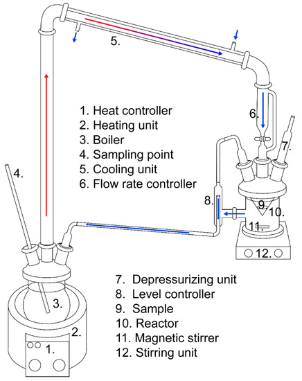
Figure 1.
Schematic overview of the dynamic leaching apparatus.
2.3.2. Static pH-Titration Test
Static pH titrations were executed to simulate exposure to external environments (oxidic and acidic conditions). The titrations were performed in water at pH 5 using dilute HNO3 (0.025M), as described earlier by the authors [14]. In this study, the samples were submerged in the water and placed in a filter cloth to avoid contact with the magnetic stirrer. For each titration, 10 g of 0.3–0.6 mm fractions were used with an initial water (MilliQ, Millipore) content of 100 mL and L/S 10. The titrations were carried out at a stirring rate of 960 rpm for 24 h. For each sample, duplicate runs were executed.
2.4. Leaching Analyses
The leachate samples were filtered (0.45 µm) and acidified using concentrated HNO3 (68 vol.%) at 1 vol.% of the leachate volume for both methods. The Al, As, Ba, Ca, Cd, Cr, Cu, Fe, K, Mg, Mn, Mo, Na, Ni, Pb, Sb, V, Zn, and Si contents were analyzed by the laboratory ALS Scandinavia AB, Sweden, using ICP–AES according to SS-EN ISO 11885:2009 and US EPA Method 200.7:1994 for Ca, K, Mg, Na, and Si and ICP–SFMS according to SS-EN ISO 17294–2:2016 and US EPA Method 200.8:1994 for the other elements. Elemental concentrations in the leachates are presented as the average value (in mg/kg) of two subsamples (F06 dynamic leaching and static pH titration). The duplicate dynamic leaching runs of F06 (Figure S1) showed similar leaching patterns for the elements in the slag; however, the absolute amounts varied due to the use of industrial materials. RF02 and F13 dynamic leaching trials were single runs.
3. Results
3.1. Sample Characterization
The chemical compositions of the CaO-modified slag batches of 0.3–0.6 mm fractions are summarized in Table 1. XRD analysis of the samples shown in Figure 2a revealed that all batches were amorphous. However, F13 shows a peak matching the main peak of the spinel. The SEM–EDS measurements (Figure 3) showed that three phases/microstructures were present in the slag granules, named by their main elements as calcium iron silicate (O, Si, Fe, and Ca), copper sulfide (Cu, S, and Fe), and copper metalloid (Cu, Ni, As, and Sb). The BET surface area measurements of the subsamples (0.3–0.6 mm) are presented in Table 1.

Table 1.
Chemical compositions (wt.%) of main oxides and elements of 0.3–0.6 mm samples analyzed by ICP–MS and sample data. * Total Fe calculated as Fe2+.
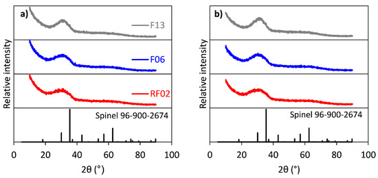
Figure 2.
XRD patterns (a) before and (b) after dynamic leaching of RF02, F06, and F13 samples.
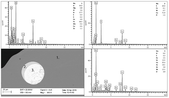
Figure 3.
SEM image with EDS point analyses for sample F06, 1—slag matrix, 2—matte, and 3—speiss.
3.2. Dynamic Leaching Test
Figure 4a,b, Figure 5a,b and Figure 6a,b show the results for the dynamic leaching test and the leaching over time (3 mL/minute for 30 days). As seen in Figure 4a,b, the main elements Si and Ca show a trend of increased leaching with increasing time and L/S. Figure 5a,b shows that Cu and Zn exhibit peak leaching during the first 1–8 days (L/S 130–900). A trend of increasing leaching is observed for As and Sb, but the extent of this increase diminishes with the increasing CaO content of samples (Figure 6a,b).
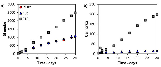
Figure 4.
Leaching values of (a) Si and (b) Ca (mg/kg) versus time from dynamic leaching tests; Ca was not determined for RF02.
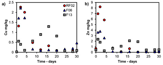
Figure 5.
Leaching values of (a) Cu and (b) Zn (mg/kg) versus time from dynamic leaching tests.
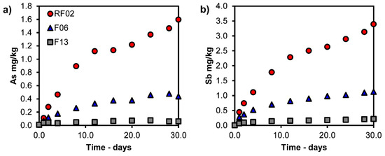
Figure 6.
Leaching of (a) As and (b) Sb (mg/kg) versus time from dynamic leaching tests.
The conditions regarding pH, conductivity, and redox after 30 days of dynamic leaching in the reactor and boiler are shown in Table 2. Furthermore, the waters in the boiler showed increasing pH values with increasing CaO in the samples; see Table 2.
Table 2.
Dynamic leaching data of leachates in the reactor and boiler after leaching for 30 days.
Secondary phases/microstructures at the sample surfaces were observed in all the samples during the dynamic leaching tests, as presented in Figure 7. Moreover, precipitates formed in the boiler in all tests. According to XRD analysis, precipitated Fe2O3 was identified after all tests, and CaSO4 was detected in F13, as shown in Figure 8. Furthermore, Si, Ca, Cu, Al, Fe, Zn, and S were detected in the precipitates using ICP–MS, as shown in Table 3.
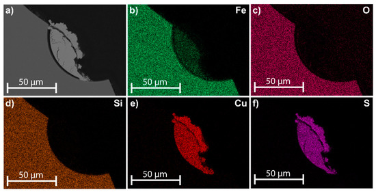
Figure 7.
EDS mapping of a typical cross-section of phases from samples (F06) after dynamic leaching. (a) SEM image; distribution of (b) Fe, (c) O, (d) Si, (e) Cu, and (f) S.
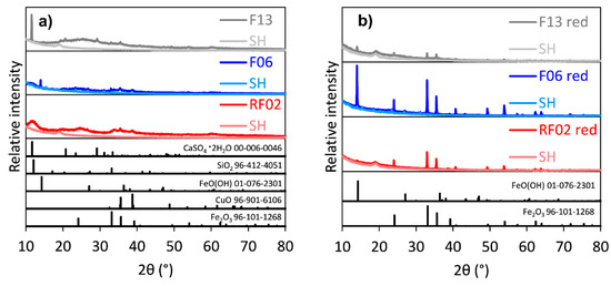
Figure 8.
XRD patterns of precipitates of RF02, F06, and F13 from dynamic leaching: (a) bottom precipitate; (b) red precipitate. SH = sample holder.
Table 3.
Quantitative screening of dynamic leaching boiler precipitates using ICP–MS (SD ± 30 wt.%); *, not determined.
3.3. Static pH-Titration Test
Table 4 shows the leaching effect in dilute HNO3 (0.025M), at pH 5, for the CaO-modified iron silicate slags. Cu, Fe, Ca, and Zn show the highest leaching values of the samples. Furthermore, Ni, As, and Sb show a trend of decrease with the increasing CaO content in the samples, while the leaching of Ca shows the opposite trend.
Table 4.
Leaching data for leachates (mg/kg), measured according to static pH titration at pH 5 for the sample size fraction of 0.30–0.60 mm. * standard deviation.
4. Discussion
4.1. Characterization
The chemical composition (Table 1) of the slags indicates decreased contents of Cu (0.69 to 0.56–0.52 wt.%), As (0.019 to 0.005 wt.%), and Sb (0.024 to 0.011–0.007 wt.%) in the CaO-modified samples compared with the reference slag (RF02). The decreased contents indicate the enhanced removal of these elements with the increasing CaO content, which was also reported earlier in the literature by Kero Andertun et al. (2021) and Bellemans et al. (2018) [15,24]. Furthermore, no decreases in the Zn (ZnO, 1.06–1.15 wt.%) content was observed. Earlier studies by Tian et al. (2021), Gorai et al. (2005), and Piatak et al. (2015) have reported on water-granulated slags with similar slag chemistries, as the studied slags are mainly amorphous [1,2,9]. The increased CaO content in the slags affects the short-range order in the slag matrix, which is shown as a sharper hump in the XRD patterns between 20° and 40° with the increasing CaO content (Figure 2a) according to Piatak et al. (2015) [9]. Ku et al. (2021) have shown that CaO (up to 20 wt.%) fully dissolves into the fayalite slag matrix via a substitution mechanism [25], which can also explain the CaO dissolution observed in our study. According to Kongoli et al. (2011) [7], the peaks in F13 (35.4 and 62.65°, Figure 2a), matching spinel, are also identified in other CaO-rich iron silicate slags.
SEM–EDS analysis (Figure 3) showed microstructures in the samples with similar compositions as the slag matrix (silicate), matte (copper sulfide), and speiss (metal(loid)). According to studies by Gorai et al. (2005), Piatak et al. (2015), and Kero Andertun et al. (2021), these phases are commonly found in iron silicate slags [2,9,14].
4.2. Leaching Trends
Results from dynamic leaching and pH titration indicate that long-term leaching is limited regarding the metal(loid) leaching (Cu, Zn, Ni, As, Sb) from the CaO-modified granulated iron silicate slags. Figure 4 shows the leaching trends of the main leachable elements in the slag (Si and Ca) using the dynamic leaching method. These elements show increasing leaching trends over time (up to 30 days, L/S > 3000) as measured in the boiler. The leached elements from the sample in the reactor are transported to the boiler through water, where they accumulate following the element’s predominant species in the neutral regime (pH 6–7); see Table 2 and Figure 9a–f. According to the Fe–OH predominance diagram in Figure 9c, Fe is preferentially found in a solid phase (oxide) in the reactor. However, some Fe becomes dissolved during the trials and precipitates to Fe2O3 in the boiler during dynamic leaching; see Figure 8b. The water in the boiler enters the neutral/slightly alkaline regime (pH 8–9) after the dynamic leaching trials; according to Table 2, the pH increases as Ca leaching increases with the increasing CaO content of the sample. Earlier, Piatak et al. (2015) noted the correlation between the increased Ca leaching and the increasing CaO content in slag [9].
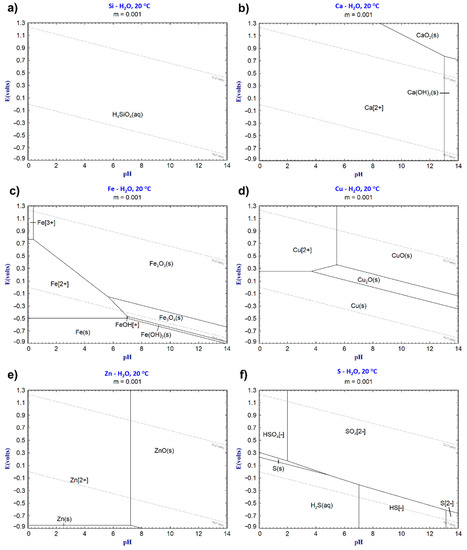
Figure 9.
Predominant phase diagrams of (a) Si, (b) Ca, (c) Fe, (d) Cu, (e) Zn, and (f) S plotted using FactSage 8.1.
As seen in Figure 5a,b, Cu and Zn show similar leaching trends and peaks for the dynamic leaching method after a specific leaching time. Changes in the predominant phases of the elements explain the peaks for Cu and Zn as resulting from the increasing pH in the boiler according to Table 2 and Figure 9d,e. Lidelöw et al. (2017) studied the leaching from a slag similar to RF02 in a field testbed for ten years and found that the leaching values peaked after four years for Cu and after two years for Zn [26]. Their explanation for the leaching peaks was the higher reactivity before aging reactions and the depletion of easily soluble elements [26], which likely also occurred for our studied slags. However, the decreased leaching due to the saturation of elements in the leachate cannot be neglected, both in the field test and in this study. The precipitates in this study were found to contain Cu and Zn, as shown in Table 3.
Moreover, the static pH titration results using dilute nitric acid (0.025M) demonstrated that at pH 5 (Table 4), the samples were leached from a potential external source under acidic and oxidating conditions. The overall leaching values increased significantly, as expected, compared with the maximum dynamic and reference (EN12457-2 [15]) leaching values in Table 5, indicating leaching sensitivity for external acidic and oxidating sources. The pH titration leaching values increased for Zn (1.2–2.8 times), Ni (1.9–2.8 times), and Cu (11–22 times), exceeding the previous maximum dynamic leaching values. Furthermore, Cu (26.5–57.6 mg/kg) and Fe (24.1–41.3 mg/kg) show the highest leaching values, followed by Ca (5.2–31.2 mg/kg), and Zn (6.7–11.6 mg/kg), according to Table 4 and Table 5. Among these elements, Ca, Cu, and Zn are predominately dissolved at pH 5 according to the respective Eh–pH diagrams in Figure 9b,d,e. According to Kero Andertun et al. (2022), the leaching of Cu partly originates from the matte (Cu, S) and speiss (Cu, Ni, As, Sb) [14]—matte and speiss are present as inclusions at the slag surfaces in this study, as shown in Figure 3 and Figure 7. Thereby, the leaching of matte and speiss explains the Cu leaching increase compared to the other leaching methods due to oxidation by the nitric acid at pH 5. Fe, located in the slag matrix, should not dissolve extensively at pH 5 according to Figure 9c. Figure 3 shows that Fe is also found in matte and speiss. Nevertheless, compared to the other slag phases (matte and speiss), the slag matrix is the main source of Fe leaching according to our earlier study [14]. Fe leaching is highest for the CaO-modified slags but decreases slightly with the increasing CaO content.
Table 5.
Leaching comparison (mg/kg) for leachates measured according to batch leaching, dynamic leaching (DL) on days 1, 4, and 30, and maximum leaching values (day); static pH titration at pH 5 for the sample size fraction of 0.30–0.60 mm and reference batch leaching test in our earlier study [15].
These results confirm that the leaching from CaO-modified slags is mainly influenced by external sources, which generate acidic and oxidic conditions, as the slag showed limited leaching of Cu, Ni, and Zn during dynamic leaching (Table 5) and compliance tests in an earlier study by Kero Andertun et al. (2021) [15]. Moreover, Kero Andertun et al. (2022) indicate that the amount of slag inclusions (Cu, Ni, As, and Sb) influences the magnitude of leaching [14]. Furthermore, the leaching trends of Cu, Zn, and Ni versus the CaO content in the slags are similar among the leaching methods, except for the pH titration—see Table 5—and decrease with the increasing CaO content. These trends of the leaching methods, except for pH titration conditions, indicate the long-term decreased leaching of Cu, Zn, and Ni from the CaO-modified slags with the increasing CaO content. The chemical content of Zn (ZnO, 1.06–1.15 wt.%) shows minor variance after the slag processing comparing F06 and F13, supporting decreased leaching. The contents of Cu (0.56–0.52 wt.%) and Ni (0.035–0.018 wt.%) show a decrease (of 7% and 49%) with the increasing CaO content in the samples, whereby Cu and Ni removal during slag processing contributes to decreased leaching. Moreover, As and Sb show long-term decreasing leaching trends (Table 4 and Figure 6) with the increasing CaO content in the sample, since the contents of As (0.05 wt.%) and Sb (0.007–0.011 wt.%) show little difference when comparing F06 and F13 (Table 1).
4.3. Secondary Phases and Leaching Precipitates
From the dynamic leaching, secondary phases (Cu–S compounds) were found at the sample surfaces using SEM–EDS analysis, as presented in Figure 7a–f. Potysz et al. (2015), Jarošíková et al. (2017), and Piatak (2018) have reported similar secondary phases in slag dumps [11,16,27]. The formation of secondary phases (such as Cu2S) can be explained by galvanic conversion according to Reactions (1) and (2),
where the two slag inclusions—matte (illustrated as bornite, Cu5FeS4) and speiss (illustrated as metallic Cu)—are present. The reactions are summarized in Reaction (3) from Reactions (1) and (2), described by Huang (2016) [28]:
The final pH conditions in the boiler after 30 days (Table 2) reached the neutral/alkaline regime (pH 8.1–9.1) for all the trials during the dynamic leaching process, supporting the possibility of the acid-consuming (H+) galvanic conversion Reaction (3).
In all of the dynamic leaching experiments, the leachates formed precipitates at the walls (red) and bottom of the heated boiler (Table 3 and Figure 8a,b). A red precipitate was found on the boiler walls, consisting of Fe2O3 and FeO(OH), as shown in Figure 8b. The formation of this precipitate indicates that Fe leaches under dynamic leaching conditions, but the mechanism of leaching depends on the Fe source. These Fe compounds are likely received from the products of the galvanic conversion Reaction (3), sulfide dissolution Reactions (4) and (5) described by Li et al. (2013) [29] or the dissolution of the slag matrix (6) as described by Griffioen (2017) [30], where Fe2O3 is formed by Reaction (7) in the heated boiler. According to Li et al. (2013) and Hong et al. (2021), the galvanic conversion and sulfide dissolution indicate a two-stage mixed controlled leaching mechanism [29,31], while the dissolution of the slag matrix indicates diffusion-controlled leaching as reported by Meshram et al. (2017) for a similar iron silicate slag [32].
The precipitates at the bottom of the boiler contain mainly Si, Cu, Fe, Ca, Al, and Zn; see Table 3. Moreover, the phases Fe2O3, FeO(OH), CuO, SiO2, and CaSO4·2H2O are identified according to XRD analyses of the precipitates in Figure 8a. Among the identified phases, CaSO4·2H2O is likely formed in the F13 precipitate due to the Ca and S concentrations in the precipitate (Figure 4b) and the higher CaO content in the slag. Earlier, Xie et al. (2012) reported that gypsum (CaSO4) was identified at the surfaces of CaO-rich and sulfur-containing slags after hydration tests [33]—the slags in this study were also continuously hydrated during the dynamic leaching tests. The precipitation of Fe, Cu, and Zn (Figure 8a and Table 3) in the boiler at pH 8.1–9.1 and redox 0.13–−0.02 V, as shown in Table 2, is in accordance with the predominant phases (Fe2O3, CuO, and ZnO) shown in Figure 9d–f. The lack of identified Fe2O3 in the slag samples after the dynamic leaching trials (Figure 2b) further confirms the Fe dissolution from the slag samples in the reactor and during transportation to the boiler.
The Reactions (2), (4), and (5) generate acid. Still, since both O2 (semi-closed system, Figure 1) and the sulfides at the sample surfaces are limited owing to the experimental system design and inclusion distribution, the acidification effect is limited during the dynamic leaching experiments. The acidification reactions are minor compared to other reactions, such as Reaction (3) and the release of Ca, which also increase the pH value of the leachate in the reactor; see Table 2. These reactions and the pH increase suggest an overall diffusion-controlled leaching mechanism in the CaO-modified slags in accordance with Meshram et al. (2017) [32].
4.4. Long-Term Leaching Effects
Commonly, smelter-specific slags with unique slag chemistries and raw material inclusions are investigated for environmental properties such as leaching. In this study, the long-term leaching effects versus various CaO content levels were determined for different slag compositions. The results indicate that the CaO-modified slags show limited peak leachability of Cu, Ni, Zn, As, and Sb (<9.33 mg/kg) when submersed in distilled and recirculating water, up to L/S above 3000 (Table 5). Furthermore, the peak leachability of these elements decreases with the increasing CaO content in the slag. This demonstrates that the leaching decreases as the slag remains amorphous (Figure 2b) over time, independent of the changed slag chemistry.
Furthermore, the inclusions in the slag and at the slag surfaces (matte and speiss) show the long-term leaching contribution of Cu, Ni, As, and Sb, as was earlier concluded by the authors for a shorter time period (L/S 10, 24 h [14]). According to Figure 7a–f, the leaching of the slag inclusions (present at the slag surface) is limited during the forced leaching in distilled water using the dynamic leaching method. The formation of secondary phases on the slag inclusions (Figure 7a–f) indicates that the galvanic effect is the main reaction of the slag inclusions, which releases dissolved elements such as Fe2+ from the sulfides, as discussed by Hong et al. (2021) [31]. However, the leaching contributions of slag inclusions are dependent on external factors such as access to O2, CO2 or acids/bases. Limiting access to external factors will minimize the leachability of the slag inclusions.
5. Conclusions
From this research, the following conclusions are drawn:
- The 0.3–0.6 mm fractions of the CaO-modified samples exhibit an amorphous XRD pattern and, hence, indicate that CaO has dissolved into the slag matrix.
- The CaO-modified slags demonstrated limited long-term leachability of Cu, Zn, As, and Sb, whereby the leaching decreases with the increasing CaO content in the slag, unrelated to dilution by CaO.
- Secondary phases (Cu–S-containing) formed on the surfaces of the slag inclusions (matte and speiss) during the dynamic leaching experiments according to SEM–EDS analysis.
- Compared to the dynamic leaching method, static pH titration at pH 5 and oxidating conditions increase the leaching of the slag inclusion elements (Cu, Ni, As, and Sb) to a greater extent.
- Limiting access to external factors such as acidification and oxidation agents (CO2 and O2) minimizes the potential leaching contribution from slag inclusions in an application.
Supplementary Materials
The following supporting information can be downloaded at: https://www.mdpi.com/article/10.3390/min12111442/s1, Figure S1: Leaching data of F06, duplicate runs: (a) Si, (b), Ca, (c) Zn, (d) Cu, (e) As, (f) Sb.
Author Contributions
Conceptualization, J.K.A., C.S. and F.E.; methodology, J.K.A., C.S. and F.E.; software, J.K.A.; validation, J.K.A., P.P., F.E. and C.S.; formal analysis, J.K.A.; investigation, J.K.A.; writing—original draft preparation, J.K.A.; writing—review and editing, J.K.A., P.P., F.E. and C.S.; visualization, J.K.A.; supervision, P.P., F.E. and C.S. All authors have read and agreed to the published version of the manuscript.
Funding
This study was funded by Boliden through Bolidenpaketet and was conducted within CAMM2 (Center of Advanced Mining and Metallurgy) at Luleå University of Technology.
Data Availability Statement
The data presented in this study are available in the article or Supplementary Materials.
Conflicts of Interest
The authors declare no conflict of interest.
References
- Tian, H.; Guo, Z.; Pan, J.; Zhu, D.; Yang, C.; Xue, Y.; Li, S.; Wang, D. Comprehensive review on metallurgical recycling and cleaning of copper slag. Resour. Conserv. Recycl. 2021, 168, 105366. [Google Scholar] [CrossRef]
- Gorai, B.; Jana, R.K.; Premchand. Characteristics and utilisation of copper slag—A review. Resour. Conserv. Recycl. 2003, 39, 299–313. [Google Scholar] [CrossRef]
- Zhao, W.; Wang, M.; Yang, B.; Feng, Q.; Liu, D. Enhanced sulfidization flotation mechanism of smithsonite in the synergistic activation system of copper–ammonium species. Miner. Eng. 2022, 187, 107796. [Google Scholar] [CrossRef]
- Dhir, O.B.E.R.K.; de Brito, J.; Mangabhai, R.; Lye, C.Q. Sustainable Construction Materials: Copper Slag; Woodhead Publishing: Sawston, UK, 2016. [Google Scholar]
- Ali, M.B.; Saidur, R.; Hossain, M.S. A review on emission analysis in cement industries. Renew. Sustain. Energy Rev. 2011, 15, 2252–2261. [Google Scholar] [CrossRef]
- Al-Jabri, K.S.; Taha, R.A.; Al-Hashmi, A.; Al-Harthy, A.S. Effect of copper slag and cement by-pass dust addition on mechanical properties of concrete. Constr. Build. Mater. 2006, 20, 322–331. [Google Scholar] [CrossRef]
- Kongoli, F.; McBow, I.; Yazawa, A. Phase relations of ferrous calcium silicate slag and its possible application in the industrial practice. High Temp. Mater. Process. 2011, 30, 491–504. [Google Scholar] [CrossRef]
- Feng, Y.; Yang, Q.; Chen, Q.; Kero, J.; Andersson, A.; Ahmed, H.; Engström, F.; Samuelsson, C. Characterization and evaluation of the pozzolanic activity of granulated copper slag modified with CaO. J. Clean. Prod. 2019, 232, 1112–1120. [Google Scholar] [CrossRef]
- Piatak, N.M.; Parsons, M.B.; Seal, R.R. Characteristics and environmental aspects of slag: A review. Appl. Geochem. 2015, 57, 236–266. [Google Scholar] [CrossRef]
- Vítková, M.; Ettler, V.; Mihaljevič, M.; Šebek, O. Effect of sample preparation on contaminant leaching from copper smelting slag. J. Hazard. Mater. 2011, 197, 417–423. [Google Scholar] [CrossRef]
- Potysz, A.; van Hullebusch, E.D.; Kierczak, J.; Grybos, M.; Lens, P.N.L.; Guibaud, G. Copper metallurgical slags—Current knowledge and fate: A review. Crit. Rev. Environ. Sci. Technol. 2015, 45, 2424–2488. [Google Scholar] [CrossRef]
- Król, A.; Mizerna, K.; Bożym, M. An assessment of pH-dependent release and mobility of heavy metals from metallurgical slag. J. Hazard. Mater. 2020, 384, 121502. [Google Scholar] [CrossRef] [PubMed]
- Ettler, V.; Johan, Z.; Kříbek, B.; Šebek, O.; Mihaljevič, M. Mineralogy and environmental stability of slags from the Tsumeb smelter, Namibia. Appl. Geochem. 2009, 24, 1–15. [Google Scholar] [CrossRef]
- Kero Andertun, J.; Samuelsson, C.; Peltola, P.; Engström, F. Characterisation and leaching behaviour of granulated iron silicate slag constituents. Can. Metall. Q. 2022, 61, 14–23. [Google Scholar] [CrossRef]
- Kero Andertun, J.; Vikström, T.; Peltola, P.; Samuelsson, C.; Engström, F. Characterisation and leaching behavior of CaO-modified iron-silicate slag produced in laboratory and industrial scales. Can. Metall. Q. 2021, 60, 294–305. [Google Scholar] [CrossRef]
- Jarošíková, A.; Ettler, V.; Mihaljevič, M.; Kříbek, B.; Mapani, B. The pH-dependent leaching behavior of slags from various stages of a copper smelting process: Environmental implications. J. Environ. Manag. 2017, 187, 178–186. [Google Scholar] [CrossRef] [PubMed]
- Koizumi, S.; Gao, X.; Sukenaga, S.; Kanehashi, K.; Takahashi, T.; Ueda, S.; Kitamura, S.-Y. Influence of Glass Structure on the Dissolution Behavior of Fe from Glassy Slag of CaO–SiO2–FeOx System. J. Sustain. Metall. 2021, 7, 583–596. [Google Scholar] [CrossRef]
- Kubuki, S.; Akagi, K.; Sakka, H.; Homonnay, Z.; Sinkó, K.; Kuzmann, E.; Kurimoto, H.; Nishida, T. Dissolution behaviour of iron silicate glass. Hyperfine Interact. 2009, 192, 31–36. [Google Scholar] [CrossRef]
- Moudilou, E.; Bellotto, M.; Defosse, C.; Serclerat, I.; Baillif, P.; Touray, J. A dynamic leaching method for the assessment of trace metals released from hydraulic binders. Waste Manag. 2002, 22, 153–157. [Google Scholar] [CrossRef]
- Potysz, A.; Kierczak, J.; Fuchs, Y.; Grybos, M.; Guibaud, G.; Lens, P.N.L.; van Hullebusch, E.D. Characterization and pH-dependent leaching behaviour of historical and modern copper slags. J. Geochem. Explor. 2016, 160, 1–15. [Google Scholar] [CrossRef]
- Cappuyns, V.; Swennen, R. The application of pHstat leaching tests to assess the pH-dependent release of trace metals from soils, sediments and waste materials. J. Hazard. Mater. 2008, 158, 185–195. [Google Scholar] [CrossRef]
- Lotfian, S.; Vikström, T.; Lennartsson, A.; Björkman, B.; Ahmed, H.; Samuelsson, C. Plastic-containing materials as alternative reductants for base metal production. Can. Metall. Q. 2019, 58, 164–176. [Google Scholar] [CrossRef]
- Gražulis, S.; Daškevič, A.; Merkys, A.; Chateigner, D.; Lutterotti, L.; Quirós, M.; Serebryanaya, N.R.; Moeck, P.; Downs, R.T.; Le Bail, A. Crystallography Open Database (COD): An open-access collection of crystal structures and platform for world-wide collaboration. Nucleic Acids Res. 2012, 40, D420–D427. [Google Scholar] [CrossRef] [PubMed]
- Bellemans, I.; de Wilde, E.; Moelans, N.; Verbeken, K. Metal losses in pyrometallurgical operations—A review. Adv. Colloid Interface Sci. 2018, 255, 47–63. [Google Scholar] [CrossRef] [PubMed]
- Ku, J.; Zhang, L.; Fu, W.; Wang, S.; Yin, W.; Chen, H. Mechanistic study on calcium ion diffusion into fayalite: A step toward sustainable management of copper slag. J. Hazard. Mater. 2021, 410, 124630. [Google Scholar] [CrossRef]
- Lidelöw, S.; Mácsik, J.; Carabante, I.; Kumpiene, J. Leaching behaviour of copper slag; construction and demolition waste and crushed rock used in a full-scale road construction. J. Environ. Manag. 2017, 204, 695–703. [Google Scholar] [CrossRef]
- Piatak, N.M. Environmental Characteristics and Utilization Potential of Metallurgical Slag. In Environmental Geochemistry: Site Characterization, Data Analysis and Case Histories, 2nd ed.; Elsevier: Amsterdam, The Netherlands, 2018; pp. 487–519. [Google Scholar]
- Huang, H.H. The Eh-pH diagram and its advances. Metals 2016, 6, 23. [Google Scholar] [CrossRef]
- Li, Y.; Kawashima, N.; Li, J.; Chandra, A.P.; Gerson, A.R. A review of the structure, and fundamental mechanisms and kinetics of the leaching of chalcopyrite. Adv. Colloid Interface Sci. 2013, 197–198, 1–32. [Google Scholar] [CrossRef]
- Griffioen, J. Enhanced weathering of olivine in seawater: The efficiency as revealed by thermodynamic scenario analysis. Sci. Total Environ. 2017, 575, 536–544. [Google Scholar] [CrossRef]
- Hong, M.; Liu, S.; Huang, X.; Yang, B.; Zhao, C.; Yu, S.; Liu, Y.; Qiu, G.; Wang, J. A review on bornite (bio)leaching. Min. Eng. 2021, 174, 107245. [Google Scholar] [CrossRef]
- Meshram, P.; Bhagat, L.; Prakash, U.; Pandey, B.D.; Abhilash. Organic acid leaching of base metals from copper granulated slag and evaluation of mechanism. Can. Metall. Q. 2017, 56, 168–178. [Google Scholar] [CrossRef]
- Xie, J.; Wu, S.; Lin, J.; Cai, J.; Chen, Z.; Wei, W. Recycling of basic oxygen furnace slag in asphalt mixture: Material characterization & moisture damage investigation. Constr. Build. Mater. 2012, 36, 467–474. [Google Scholar] [CrossRef]
Publisher’s Note: MDPI stays neutral with regard to jurisdictional claims in published maps and institutional affiliations. |
© 2022 by the authors. Licensee MDPI, Basel, Switzerland. This article is an open access article distributed under the terms and conditions of the Creative Commons Attribution (CC BY) license (https://creativecommons.org/licenses/by/4.0/).