Article

Removal of Fluorine from RECl3 in Solution by Adsorption, Ion Exchange and Precipitation

1
School of Materials Science and Engineering, University of Shanghai for Science and Technology, Shanghai 200093, China
2
State Key Laboratory of Baiyunobo Rare Earth Resource Researches and Comprehensive Utilization, Baotou Research Institute of Rare Earths, Baotou 014010, China
3
School of Materials and Metallurgy, Inner Mongolia University of Science and Technology, Baotou 014010, China
*
Authors to whom correspondence should be addressed.
Minerals 2022, 12(1), 31; https://doi.org/10.3390/min12010031
Submission received: 15 November 2021 / Revised: 20 December 2021 / Accepted: 21 December 2021 / Published: 24 December 2021
(This article belongs to the Topic Advances in Separation and Purification Techniques)

Abstract

:
In this paper, methods of effective removal of fluorine from rare earth chloride solution by adsorption, ion exchange and precipitation with lanthanum carbonate or CO2 gas as fluorine-removal agent, respectively, were studied. The relevant parameters studied for fluorine-removal percentage were the effects of the type and dosage of fluorine-removal agent, the injection flow and mode of CO2, the initial concentration of rare earth solution and initial pH value, contact time, temperature and stirring. XRD, SEM and EDS were used to analyze and characterize the filter slag obtained after fluorine removal. SEM and EDS results showed that RECO3(OH) with a porous structure was formed in rare earth chloride solution when lanthanum carbonate was used as fluorine-removal agent, and it had strong selective adsorption for F. The XRD spectra showed that F was removed in the form of REFCO3 precipitates, which indicates that the adsorbed F replaced the OH group on the surface of RECO3(OH) by ion exchange. The experimental results showed that a fluorine-removal percentage of 99.60% could be obtained under the following conditions: lanthanum carbonate dosage, 8%; initial conc. of rare earths, 240 g/L; initial pH, 1; reaction temperature, 90 °C; reaction time, 2 h. Simultaneously, a fluorine-removal process by CO2 precipitation was explored. In general, RE2(CO3)3 precipitation is generated when CO2 is injected into a rare earth chloride solution. Interestingly, the results of XRD, SEM and EDS showed that the sedimentation slag was composed of REFCO3 and RE2O2CO3. It was inferred that RE2(CO3)3 obtained at the initial reaction stage had a certain adsorption effect on F in the solution, and then F replaced CO32− on the surface of RE2(CO3)3 by ion exchange. Therefore, F was finally removed by the high crystallization of REFCO3 precipitation, and excess RE2(CO3)3 was aged to precipitate RE2O2CO3. The fluorine-removal percentage can reach 98.92% with CO2 precipitation under the following conditions: venturi jet; CO2 injection flow, 1000 L/h; reaction temperature, 70 °C; initial pH, 1; reaction time, 1.5 h; initial conc. of rare earths, 240–300 g/L; without stirring. The above two methods achieve deep removal of fluorine in mixed fluorine-bearing rare earth chloride solution by exchanging different ionic groups. The negative influence of fluorine on subsequent rare earth extraction separation is eliminated. This technology is of great practical significance for the further development of the rare earth metallurgy industry and the protection of the environment.

1. Introduction

Rare earth is indispensable strategic material for the development of new technology due to its unique magnetic, optical and electrical properties [1]. In the rare earth industry, mixed rare earth minerals, bastnaesite, monazite, ion-absorbed rare earth ore and xenotime are generally used as feedstock to produce rare earth products [2]. The mixed rare earth mines in Bayan Obo are some of the most critical rare earth mines in China and in the world because of their large reserves and output [3]. Mixed rare earth concentrates (MREC) commonly used in industry are composed of bastnaesite and monazite in a range from 7:3 to 8:2, containing 50–65% rare earth oxide (REO), 7–10% fluorine and some other impurie elements [4,5]. Considering their complex mineral composition, the main processes for treating MREC is the concentrated sulfuric-acid roasting method and a sodium-hydroxide decomposition process for the generation of rare earth minerals in China [6]. The concentrated sulfuric-acid roasting process accounts for 90% of the decomposition capacity of MREC due to its advantages of wide-grade adaptability and high capacity for processing. Mixed rare earth chloride solution (MRECS) can be obtained by decomposition by concentrated sulfuric acid at high temperatures, water leaching, impurity removal, transformation, separation and other processes [7]. Meanwhile, fluorine in MREC is basically all converted to HF gas and discharged during the concentrated sulfuric-acid decomposition process at high temperatures. The fluorine content of MRECS is less than 0.03 g/L, with a rare earth conc. of 330 g/L, allowing the adverse effects of fluorine on the extraction process to be avoided. However, the acid gases (HF, SO2, etc.) discharged by this process are difficult and costly to recover, resulting in serious environmental pollution and waste of resources. In contrast, the sodium-hydroxide decomposition process is relatively environmentally friendly due to the absence of waste gas. The high-grade REO ore (REO > 55%, wt.%) of the MREC is transformed into MRECS product after chemical calcium removal, decomposition of sodium hydroxide solution, water washing, impurity removal, dissolution of hydrochloric acid and other processes [8]. At the same time, most of the fluorine in the MREC is dissolved into the aqueous solution in the form of sodium fluoride during the water-washing process, but some of the fluorine still enters the final MRECS. The fluorine content of the final MRECS is about 0.2–0.5 g/L, with a rare earth conc. of 330 g/L. The fluorine-containing water lotion produced by alkaline process is difficult recycled because of its complex composition and high cost. Meanwhile, pollutes the environment, which is also one of the factors restricting the large-scale industrial promotion of alkaline processes [9,10,11].
Obviously, the above two processes for treating MREC both have serious environmental problems. Thus, it is necessary to develop new techniques for processing MREC to alleviate economic and environmental burdens. Therefore, a cleaner and more environmentally friendly process for MREC decomposition with hydrochloric acid and sodium hydroxide is proposed, as shown in Figure 1 [12,13], except for the part marked with a red dotted line. The most obvious feature of the new process is the use of higher-grade REO ore (REO > 65%, wt.%) in MREC used as feedstock. MRECS products can be obtained through the processes of air-oxidation roasting, hydrochloric-acid leaching, sodium-hydroxide conversion, water washing, neutralization and impurity removal, etc. Following the above processes, most of the fluorine in MREC is also dissolved into the washing solution. Because of the MREC used has higher grade and fewer impurities, as well as a reasonable decomposition process, the composition of fluorine-containing aqueous solution (mainly composed of NaF and Na3PO4) is relatively simple. Therefore, fluoride and phosphorus can be effectively recovered by fractional crystallization, which eliminates the problem of wastewater discharge in the rare earth smelting process. The fluorine content of the final MRECS is about 0.3–0.6 g/L, with a rare earth conc. of 330 g/L. The new process was validated by industrial demonstration lines and proven to be a promising green technology.
Most of the fluorine in the MREC was converted to NaF after smelting through the new process or the sodium-hydroxide decomposition process. However, there was still a small amount of F in the MRECS, which resulted in higher F content than that in the MRECS obtained by roasting with concentrated sulfuric acid, adversely affecting the subsequent extraction. F in MRECS usually consists of two parts: first, rare earth fluoride can be dissolved in aqueous solution in trace amounts; secondly, it is easy to form complex [REF]2+ suspended in solution because of the high electronegativity and small ionic radius of fluorine [14]. The complex [REF]2+ in MRECS is extremely unstable; it will release F and then transform the rare earth fluoride precipitate by stirring or standing for a long time, thus reducing the stability of the MRECS and producing adverse influences on the subsequent extraction process. It is easy to emulsify the organic phase and engineer a “third phase” in the extraction of fluorine-bearing MRECS, as well as reduce the purity of rare earth products [15]. In general industrial production, reagent is added to remove fluorine in the aqueous phase of the extraction process, but this produces a large amount of fluorine-containing wastewater, increasing the dosage of the organic phase and causing the loss of rare earth material [16,17,18].
In order to neutralize the adverse effects of fluorine in MRECS on the extraction process, rare earth compounds or CO2 gas were used as fluorine-removal agents to remove fluorine before MRECS extraction by adsorption, ion-exchange and precipitation. The obtained fluorine-containing precipitate can be used as raw material and be directly returned to the decomposition process of sodium hydroxide so as to realize the resource utilization of fluorine and the recovery of rare earth. The research process is outlined by the red dotted line in Figure 1. This study provides two new methods for effective fluorine removal in the MRECS system.

2. Materials and Methods

2.1. Sample Materials and Characterization

The initial raw material of the MRECS used in the experiment was prepared from Bayan Obo MREC by the new decomposition process of hydrochloric-acid dissolution and sodium-hydroxide decomposition. The main chemical composition and rare earth partitioning of Bayan Obo MREC are shown in Table 1 and Table 2. The detailed new process is shown in Figure 1. First, roasted concentrate was obtained by air roasting at 500 °C for 2 h in mixed rare earth concentrate. After that, the roasted concentrate was leached by hydrochloric acid at a conc. of 7 mol/L and a ratio of solid to liquid of 1:2. The acid-leaching solution and acid residue were obtained after filtration. Second, the acid residue was subjected to sodium-hydroxide decomposition at a conc. of 60% NaOH at 150 °C, and alkali slag was obtained after filtration and water washing. The alkaline filtrate returned to alkali decomposition and continued to be recycled. Third, alkali slag was added to acid-leaching solution for neutralization reaction and the impurity-removal process. After filtration, the MRECS were finally obtained as experimental raw materials, and their main components are shown in Table 3. The initial conc. range of rare earths in the MRECS was 280–300 g/L, and the initial pH range was 1–2. Analytical-grade lanthanum oxide, lanthanum hydroxide, cerium carbonate and lanthanum carbonate were used as fluorine-removal agents, all provided by Inner Mongolia Baotou Steel Hefa Rare Earth Co., Ltd. (Baotou, Inner Mongolia, China). Other analytical-grade reagents used in the experiment, including hydrochloric acid and ammonia water, were provided by Beijing Chemical Co., Ltd. (Beijing, China). The purity of carbon dioxide used in the experiment was greater than 99.999%, produced by Baotou Yunsheng Gas Co., Ltd. (Baotou, Inner Mongolia, China).

2.2. Experimental Procedure and Apparatus

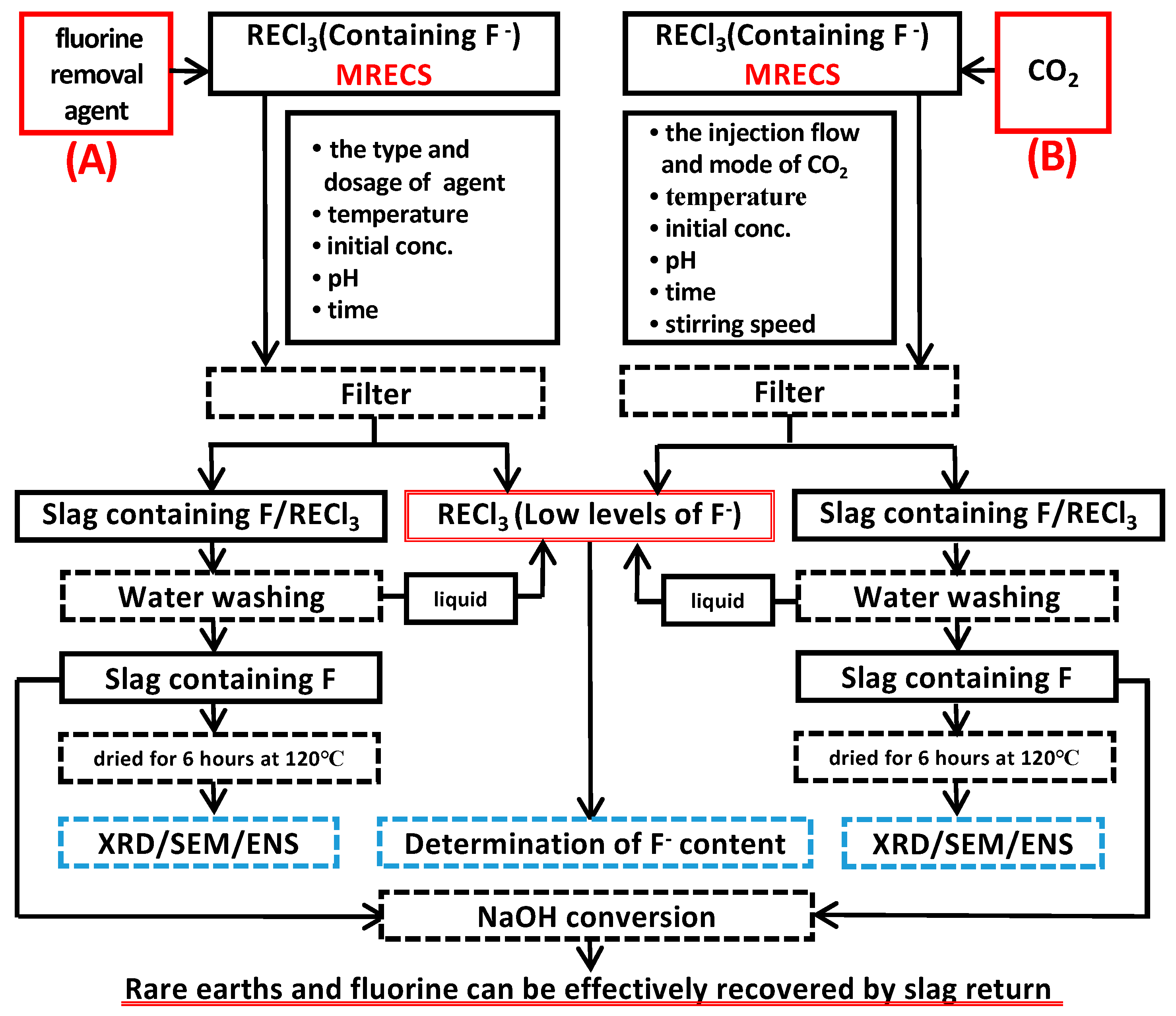
2.2.1. The Fluorine-Removal Process of Rare Earth Compound as Fluorine-Removal Agent

One liter of the MRECS was heated to the preset temperature in a water bath and stirred simultaneously. After that, the pH of the solution was adjusted with hydrochloric acid and ammonia water, and then the conc. of rare earths was diluted with deionized water or concentrated with heat. The fluorine-removal agents, lanthanum oxide, lanthanum hydroxide, cerium carbonate and lanthanum carbonate, were ground through 200 mesh and then slowly added to the prepared MRECS to remove fluorine. The dosage of fluorine-removal agent was added according to the weight percentage of the weight of fluorine-removal agent and the weight of REO in the MRECS. After a period of reaction time, filtrate and residue were obtained by vacuum filter. After that, the filtrate volume was recorded and the conc. of fluorine in the filtrate was measured. The mass of the residue was washed with deionized water three times and dried for 6 h at 120 °C in a drying oven. Then, the phase composition, microscopic morphology and main-element composition of the filter residue were measured and analyzed by X-ray diffraction, scanning electron microscopy and X-ray energy spectrometry. The experimental process is shown in Figure 2. The experimental variables considered were: (1) the type and dosage of fluorine-removal agent (lanthanum oxide, lanthanum hydroxide, cerium carbonate and lanthanum carbonate); (2) reaction temperature (25 °C, 70 °C, 90 °C); (3) reaction time (0–2.5 h); (4) initial rare earth conc. of the MRECS (60–300 g/L); (5) pH of the solution (1–5).

2.2.2. Experimental Process of Fluorine Removal by CO2 Precipitation

One liter of the MRECS was added to the reactor, heated and stirred. A vnturi jet pipe was installed at the bottom of the reactor so gas could be injected into the solution. The apparatus is shown in Figure 3. In the experiment, two types of CO2 inlet were designed: (A) CO2 gas is injected directly from the bottom of the reactor; (B) CO2 gas is sprayed into the bottom of the reactor through venturi injection. After that, the adjustment of initial feed liquid was the same as the above method. According to the two methods designed, CO2 gas with a flow rate of 200–1000 L/h was injected into MRECS for fluorine removal. After a period of reaction time, the subsequent experimental process and analysis process were the same as the above method. The experimental process is shown in Figure 2. The main experimental variables considered were: (1) the injection flow and mode of CO2; (2) reaction temperature (25 °C, 70 °C, 90 °C); (3) pH of the solution (1–5); (4) initial rare earth concentration of the MRECS (60–300 g/L); (5) reaction time (0–2.5 h); (6) stirring speed (0–500 r/min).

2.3. Analytical Methods

X-ray diffraction (XRD) analysis was carried out with an X-ray diffractometer (Japanese science company, MiniFlex 600, Tokyo, Japan) to identify the phases and compositions of the filter residue, with a scanning speed of 2 (°)/min. The structure, morphology and element distribution of the residue were characterized by a Hitachi S-3400N scanning electron microscope (SEM) and energy dispersive X-ray spectrometer (EDS). The conc. of rare earths in the solution was determined by an inductively coupled plasma optical emission spectrometer (Agilent, 5110 ICP-OES, Santa Clara, CA, USA). The content of F in the solution was determined by steam distillation EDTA titration [19]. Each sample was tested 3 times, and the test results were averaged, with a relative error of ±0.5%. Therefore, repeatability of measurement data is valid. The fluorine-removal percentage, η, was calculated as in Equation (1) below:
η ( % ) = C 0 V 0 C 1 V 1 C 0 V 0 × 100 %
where η is the fluorine-removal percentage, %; C0 is the conc. of fluorine in the MRECS, mol/L; C1 is the conc. of fluorine in the filtrate after fluorine removal, mol/L; V0 is the volume of the MRECS, mL; V1 is the volume of the filtrate after fluorine removal, mL.

3. Results and Discussion

3.1. Experimental Results of Fluorine Removal

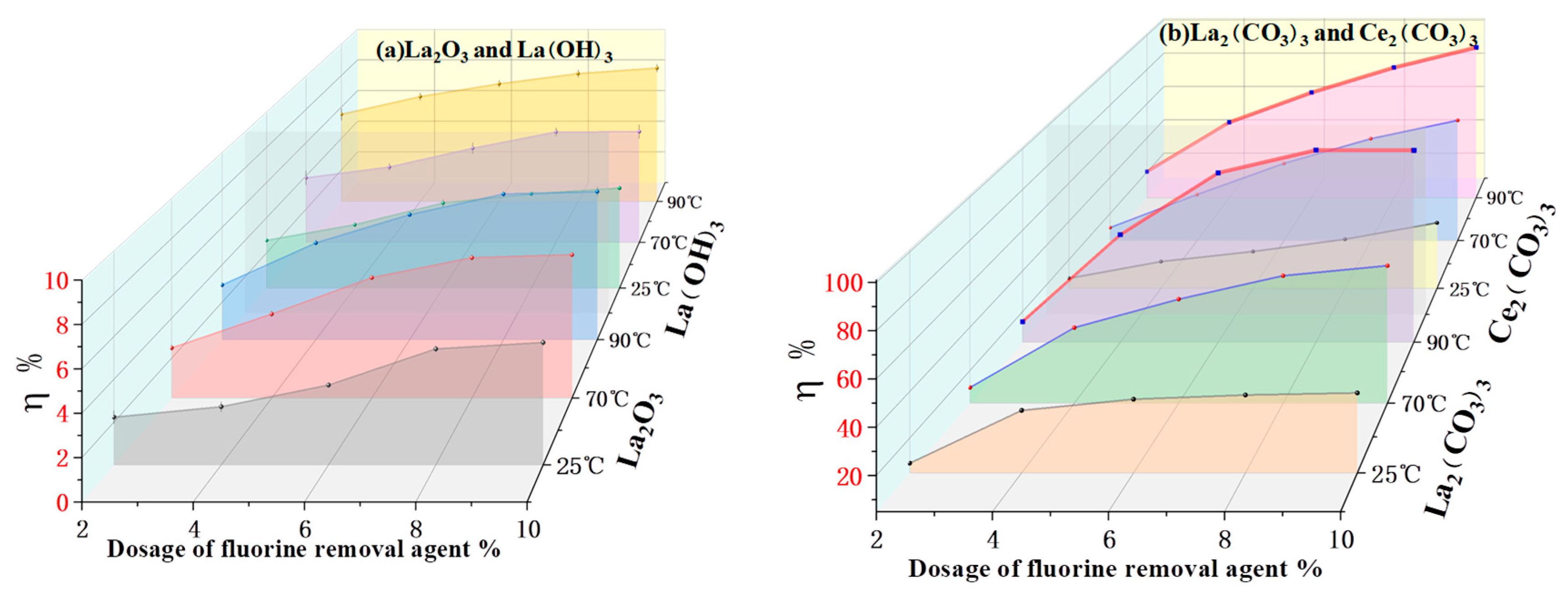
3.1.1. Rare Earth Compounds as Fluorine-Removal Agent

Figure 4 describes the type and dosage of fluorine-removal agent and the effect of reaction temperature on fluorine removal under the following conditions: initial conc. of rare earths, 240 g/L; initial pH, 1; and reaction time, 2 h. In Figure 4a,b, the effect of fluorine removal was studied, respectively, when the dosage of fluorine-removal agent was 2–10% of the weight of REO in the MRECS and the reaction temperature was 25 °C, 70 °C or 90 °C. It can be seen that the fluorine-removal percentage is less than 10% when the addition of lanthanum carbonate or cerium carbonate reaches 10%, and the temperature rises to 90 °C. However, the fluorine-removal effect of lanthanum carbonate and cerium carbonate is very obvious; with an increase in the dosage of fluorine-removal agent and increased reaction temperature, the fluorine-removal percentage is significantly improved. It can also be seen that the optimal fluorine-removal percentage reaches 99.36% with a lanthanum carbonate dosage of 8% and a reaction temperature of 90 °C, which is better than the results obtained under the same conditions but a cerium carbonate dosage of 10%. Therefore, lanthanum carbonate was selected as the optimal fluorine-removal agent in this experiment, and the subsequent experimental study of conditional variables was carried out.

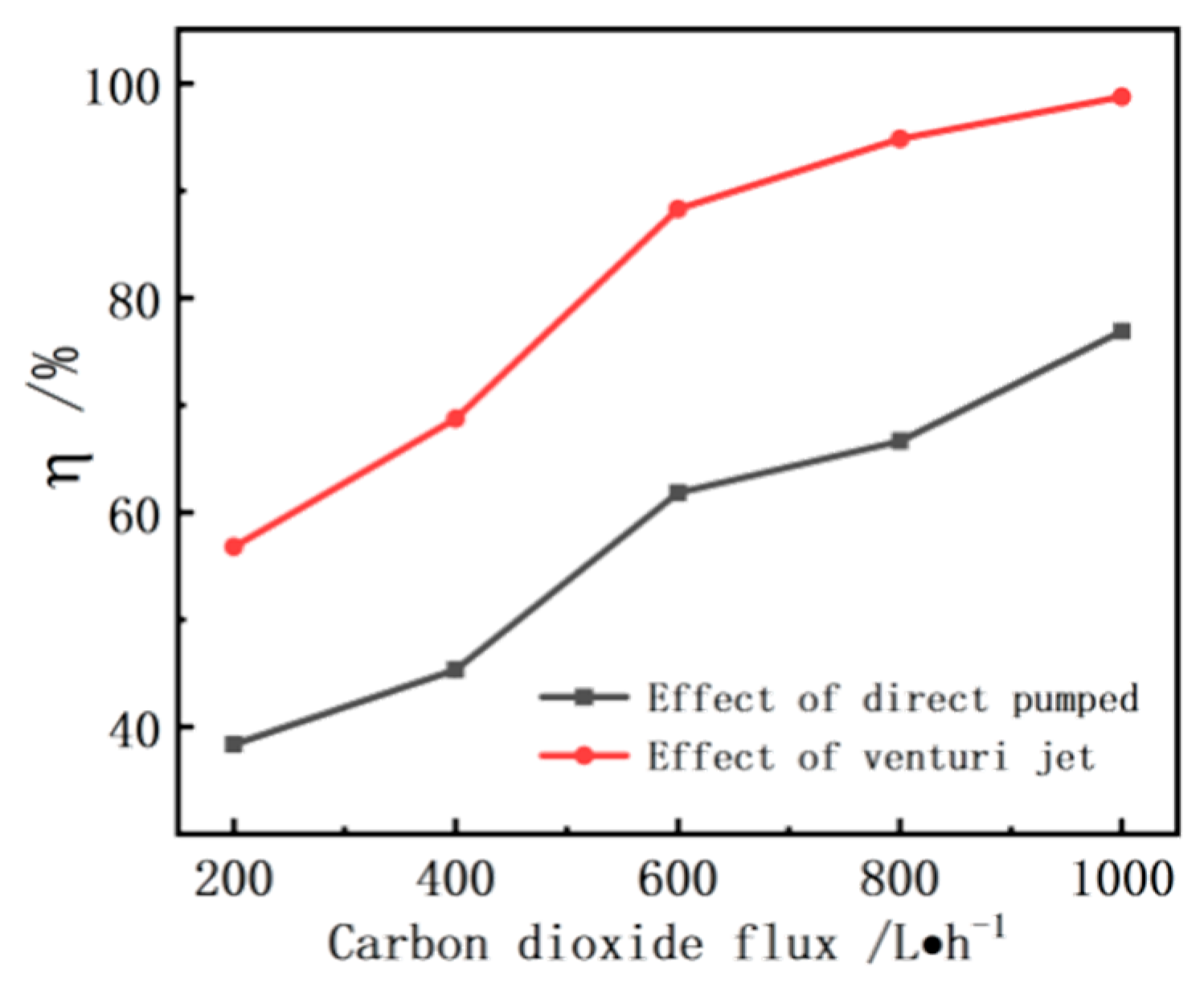
3.1.2. Fluorine Removal by CO2 Precipitation

In the experiment, two methods of CO2 injection were adopted, as shown in Figure 3. The effect of CO2 injection flow rate on fluorine-removal percentage was studied under the following conditions: initial conc. of rare earths, 240 g/L; reaction temperature, 70 °C; initial pH, 5; and reaction time, 1.5 h. As shown in Figure 5, the fluorine-removal percentage increased significantly with the increase in CO2 injection flow rate, and the fluorine removal effect of venturi injection was significantly greater than that of direct injection. This reaction involves a gas-liquid-solid three-phase reaction, and the key to improving the reaction rate is to ensure uniform dispersion of gases, liquids and solids. However, carbon dioxide can instantly form numerous diffuse microbubbles and disperse evenly into the reaction system under the action of the venturi injection. Not only can it strengthen the stirring solution and increase the gas-liquid-solid three-phase contact; it can also break the chemical equilibrium of fluoride in the solution by using the principle of chemical kinetic perturbation, so as to improve the reaction rate and the efficiency of mass and heat transfer. The removal percentage of fluorine reached 98.57% under the conditions of venturi injection and an injection flow rate of 1000 L/h. Therefore, the subsequent experiments were carried out with venturi injection and a CO2 injection flow rate of 1000 L/h.

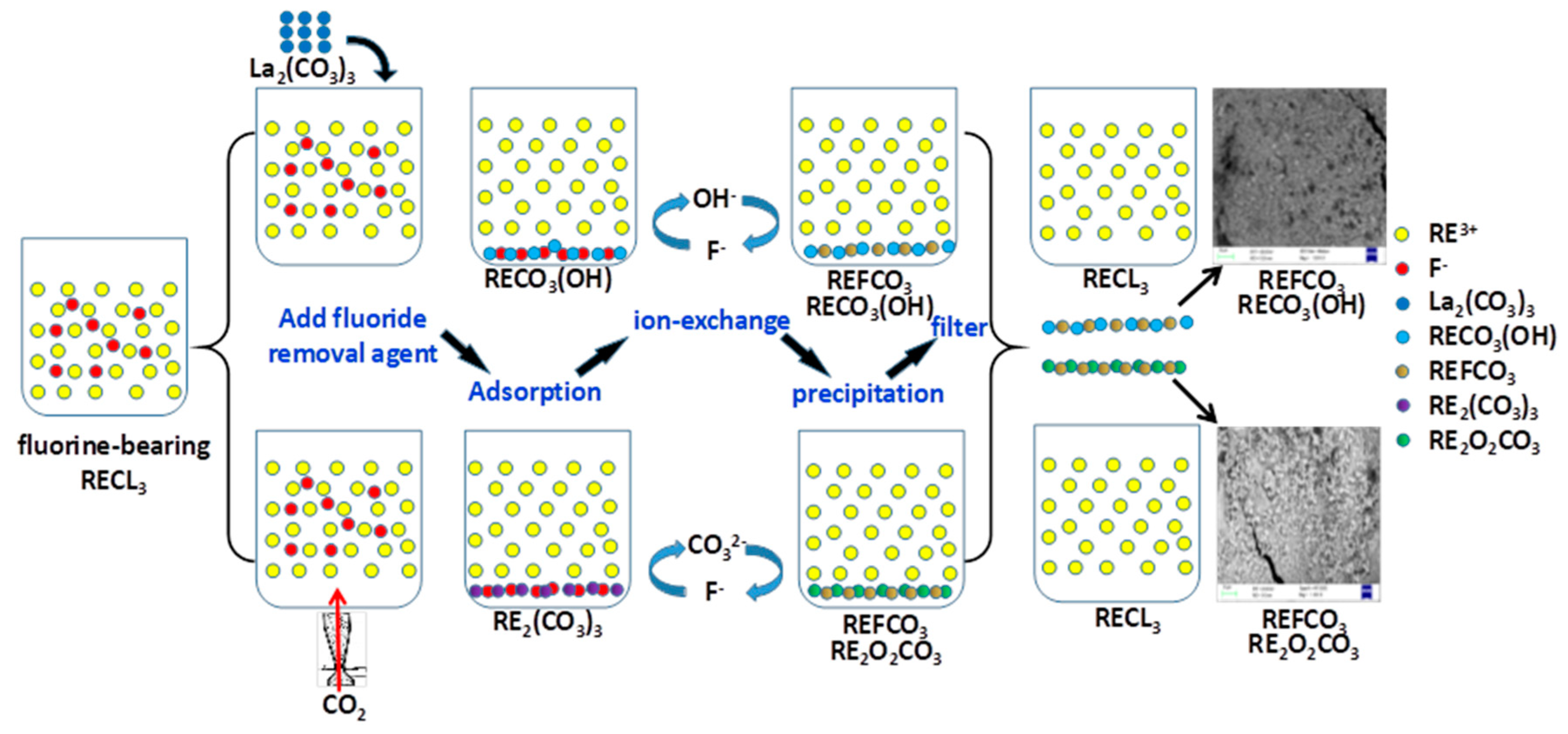
3.2. Mechanism of Fluorine Removal

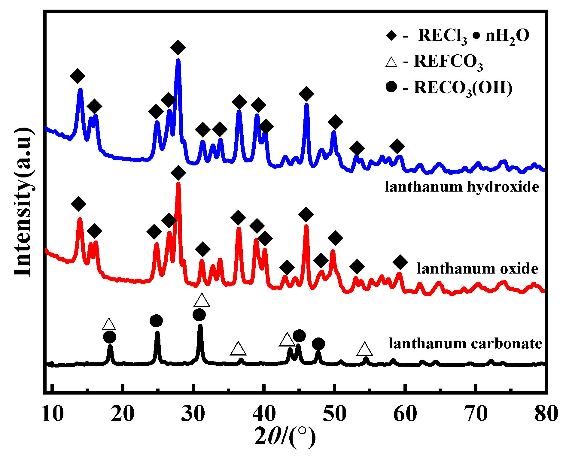
3.2.1. Fluorine-Removal Mechanism of Rare Earth Compounds

In order to reveal the mechanism of fluorine removal of various fluorine-removal agents, the XRD results of the filter residues obtained under the conditions of optimal fluorine-removal percentage are shown in Figure 6. It can be seen that the main phase of precipitation residue is RECl3 × H2O, and the other phase is CaCl2 × nH2O in the case of lanthanum oxide or lanthanum hydroxide as fluorine-removal agent, respectively. However, the main phase of the precipitated residue is RECO3(OH) and REFCO3 in cerium carbonate or lanthanum carbonate as fluorine-removal agent.
In order to further study the mechanism of fluorine removal, SEM and EDS analyses were carried out on the precipitated slag. Figure 7 and Figure 8 show that the main phase of the precipitate is RECl3 × nH2O and CaCl2 × nH2O, with lanthanum oxide and lanthanum hydroxide as the fluorine-removal agent, which is consistent with the XRD results. Although the filtrate residue was washed with ionic water three times, a small amount of rare earth chloride and calcium chloride cannot be washed away. RECl3 × nH2O has a clear sequence of precipitation and crystallization due to the different shades of light and dark in the backscattered electron map. The precipitation slag forms long, columnar crystals with a high degree of crystallization (points 1 and 2 in Figure 7a and points 1 and 2 in Figure 8a) under the conditions of sufficient solute and stable crystallization environment in the early stage. RECl3 × nH2O gradually forms a loose and porous granular aggregate (point 3 in Figure 7a and point 3 in Figure 8a) due to a lack of solute at the later stage. From the results of EDS spectrum analysis, the levels of rare earths in early RECl3 × nH2O are higher than those in late RECl3 × nH2O, and none of the phases contain fluorine. However, there is still a certain fluorine-removal effect in the case of using lanthanum oxide or lanthanum hydroxide as the fluorine-removal agent, as shown in Figure 4a. This may be due to the relatively poor crystallinity of porous pores formed in RECl3 × nH2O in the late phase, which has a certain adsorption effect relative to F. However, because of the low adsorption, there is no F peak in the EDS spectrum of the RECl3 × nH2O phase. This corresponds to the weak fluorine-removal percentage in Figure 4a.
Both of the two precipitated slag samples contain a certain amount of CaCl2 × nH2O, but their morphologies are tvery different. Figure 7b shows that CaCl2 × nH2O obtained with lanthanum oxide as fluorine-removal agent is mainly produced as microcrystalline aggregate. According to the EDS spectrum analysis, there are no other elements in the CaCl2 × nH2O phase, which indicates that the precipitation has a high crystallinity and does not adsorb or carry other elements in the solution. As shown in Figure 8b, the CaCl2 × nH2O obtained with lanthanum hydroxide as fluorine-removal agent is mainly formed in scales, with well-developed internal pores, which may have a strong adsorption capacity for ions in the solution. EDS spectrum analysis showed that it contains a small amount of Si, K, S and other elements but no F. It indicates that F in the solution is relatively stable, and F cannot be removed adsorption alone.
Figure 9 and Figure 10 show that the main composition of the precipitated residue is RECO3(OH) and REFCO3 mixed phase with cerium carbonate or lanthanum carbonate as fluorine-removal agent, containing a small amount of RECl3 × nH2O as a particulate inclusion in the mixed phase. This is consistent with the XRD pattern results in Figure 6. The mixed phase of precipitated slag shows a porous morphology, which has a good selective adsorption effect on F [19]. It can be seen from the results of EDS spectrum analysis that there is a spectral peak, with strong F in the mixed phase, which proves that a large amount of F in the leaching solution enters into the precipitated slag and has a significant effect of fluorine removal. At the same time, it can be found that although the added fluorine-removal agent is a single rare earth carbonate (lanthanum carbonate or cerium carbonate), the precipitation slag is produced in the form of mixed rare earth basic carbonate and fluorocarbon. Therefore, it can be concluded that the single rare earth carbonates added to the MRECS first decompose into La3+, Ce3+ and CO32−, most CO32− would decompose into H2O and CO2, and part of the CO32− would combine with RE3+ in the solution to generate RE2 (CO3)3 precipitation again. With the change of the environment of the solution system, especially at higher temperatures, RE2(CO3)3 was able to be hydrolyzed into RECO3(OH), and CO2 was released again, which also indicates that the pores of the mixed phase may be caused by the release of CO2 [20,21]. In this process, the porous surface of tRECO3(OH) has a strong adsorption effect on F in the solution, and the adsorbed F replaces OH on the RECO3(OH) surface by ion exchange [22,23,24,25,26,27,28,29,30]. Finally, tREFCO3 is generated on the RECO3(OH) surface. This is consistent with the results of the XRD pattern. The reaction process is as follows:
La2 (CO3)3 + 6H+ → 2La3+ + 3H2O + 3CO2
Ce2 (CO3)3 + 6H+ → 2Ce3+ + 3H2O + 3CO2
3CO32− + 2RE3+ → RE2(CO3)3
RE2(CO3)3 + OH + H2O → 2RECO3(OH) ↓ + HCO3
RECO3(OH) + F + H+ → REF(CO3) ↓ + H2O
It can be seen from Figure 4b that the amount of lanthanum carbonate is less than that of cerium carbonate when the same fluorine-removal percentage is achieved. This is because the solubility of lanthanum carbonate is greater than that of cerium carbonate [8]. Therefore, a hydrolysis reaction is more likely to occur in the solution, and more CO32− is effectively produced, thus promoting the formation of precipitation.

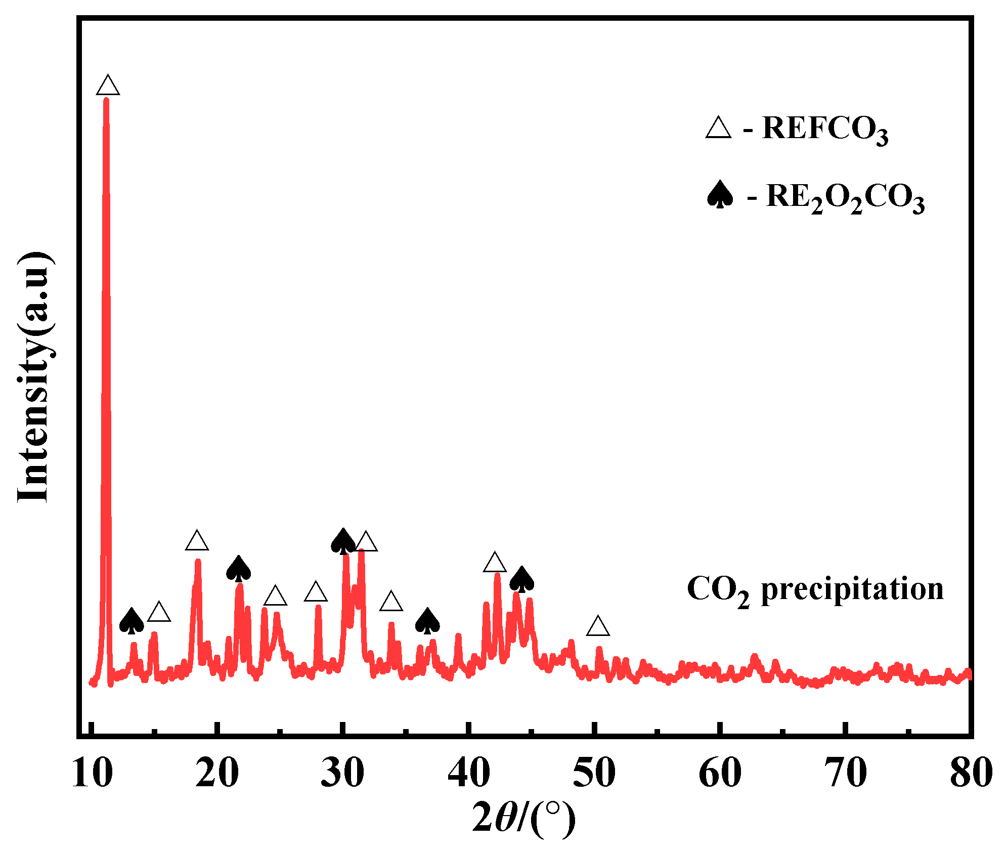
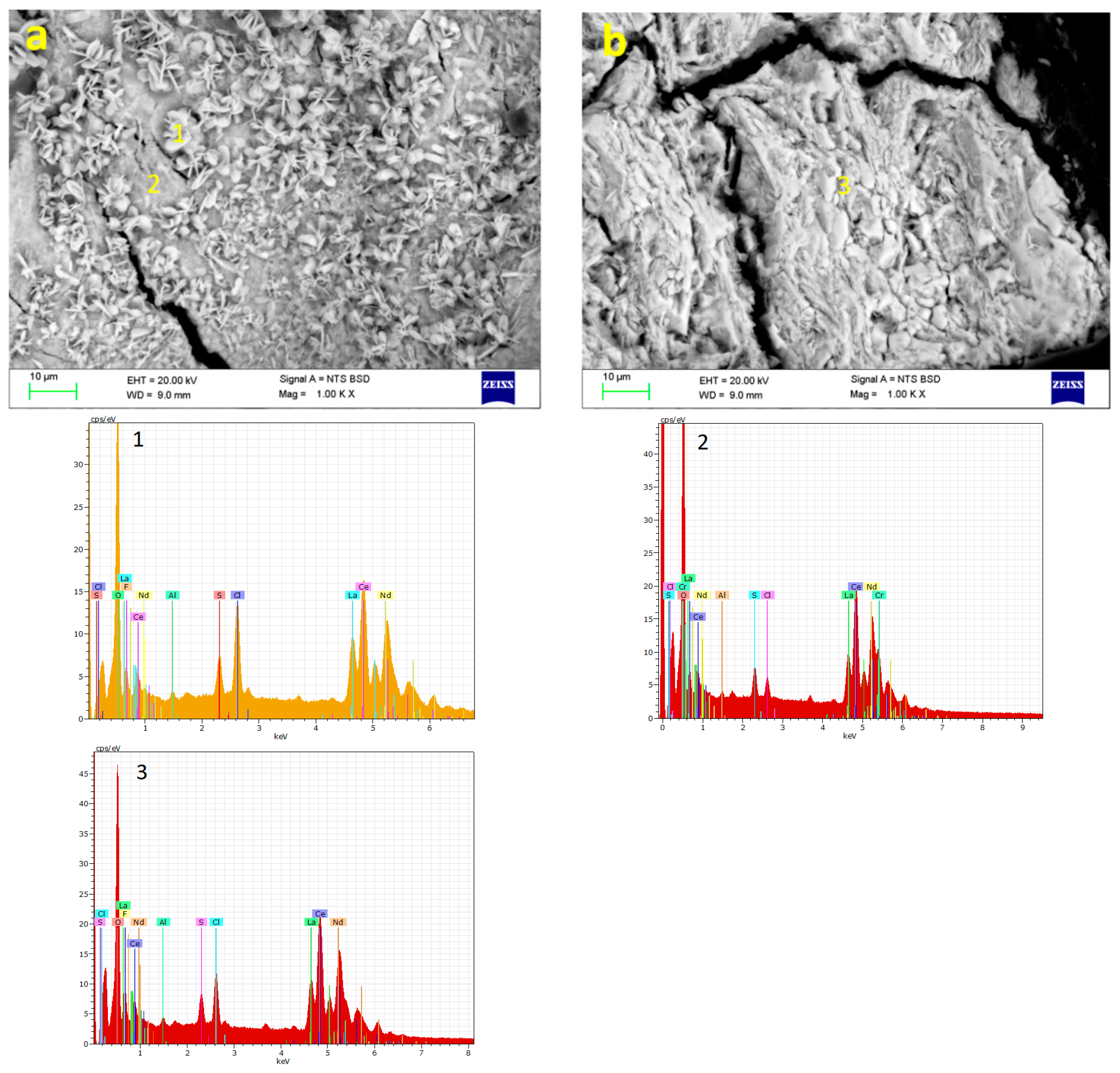
3.2.2. Fluorine-Removal Mechanism of CO2 Precipitation

In order to reveal the mechanism of fluorine removal by the CO2 precipitation method, the filtrated slag was analyzed by XRD. According to Figure 11, the main phases of the precipitated slag were REFCO3 and RE2O2CO3. At the same time, SEM and EDS spectra of the filter residue were analyzed. It can be seen from Figure 12 that REFCO3 and RE2O2CO3 were closely embedded together. The REFCO3 phase mainly presents the output of euhedral-granular plate aggregate of particles with a high degree of crystallization (point 1 in Figure 12a), and some of them show an output of hypidiomorphic-granular aggregate (point 3 in Figure 12b). The RE2O2CO3 phase mainly presents an output of aphanitic-texture granular aggregate with a low degree of crystallization (point 2 in Figure 12a). EDS spectrum analysis shows that there was a small amount of Cl and S in the REFCO3 and RE2O2CO3 phases, which may be caused by the loading band in the precipitation process.
In general, CO2 will react with OH in the solution to form CO32− when CO2 is injected into the MRECS. Subsequently, CO32− combined with RE3+ to form RE2(CO3)3, and at the same time, F in the solution was adsorbed by RE2(CO3)3, replacing CO32− on the surface of RE2(CO3)3 by ion exchange. Finally, the REFCO3 phase with a higher degree of crystallization was formed. With the completion of adsorption and precipitation of F in the solution, F was finally removed by means of precipitation to generate REFCO3. The remaining RE2(CO3)3 in the solution was gradually aged to generate RE2O2CO3 precipitate with a low degree of crystallization. This is consistent with the results of XRD analysis. The main reactions are as follows [31,32,33,34,35].
CO2 + 2OH → CO32− + H2O
3CO32− + 2RE3+ → RE2(CO3)3
RE2(CO3)3 + 2F → 2REF(CO3) + CO32−
RE2(CO3)3 → RE2O2CO3 + 2CO2

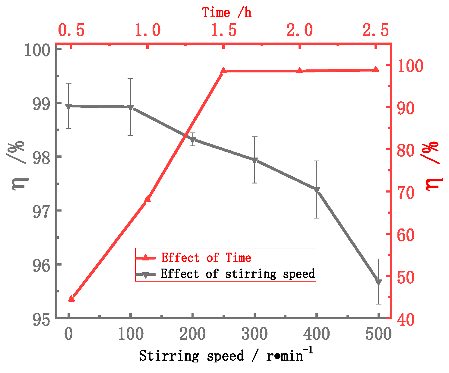
3.3. Conditional Experiments of Fluorine Removal

3.3.1. Conditional Experiment of Lanthanum Carbonate as Fluorine-Removal Agent

Figure 13 depicts the effect of initial conc. of rare earths from 60 to 240 g/L on fluorine removal. The fluorine-removal percentage reached 89.28% at an initial conc. of rare earths of 60 g/L. With an increase in concentration, the fluorine-removal percentage gradually increased and reached 98.65% at 240 g/L. With further increases in concentration, the fluorine-removal percentage decreased slightly and then remained above 98%. However, a high conc. of rare earths increases the adsorption capacity of porous RECO3(OH) to RE3+, which causes a rapid increase in the amount of precipitated slag. The amount of precipitated slag increased from 3.16 g to 7.42 g when the initial conc. of rare earths increased from 240 g/L to 300 g/L. Too much sediment returned to the process leads to an increase in economic costs. Therefore, the optimal initial concentration is of rare earths is considered to be 240 g/L.
Figure 14 shows the effect of initial pH and reaction time on fluorine removal. First, the initial pH was adjusted to the desired range of 1–5 with ammonia water before the reaction. The results show that the fluorine-removal percentage decreased from 98.6% to 63.33% when initial pH increased from 1 to 5. This may be because an increase in initial pH is not conducive to the dissolution of lanthanum carbonate, which cannot provide more effective CO32− to the rare earth chloride solution, leading to a decrease in fluorine-removal percentage. It is also possible that with an increase in pH, the conc. of OH on the surface of precipitated RECO3(OH) also increases, which intensifies ion competition and reduces the ion-exchange rate between F and OH [29]. Therefore, the optimal initial pH obtained by the experiment is equal to 1. Secondly, the fluorine-removal percentage increased significantly with the extension of reaction time and reached 98.80% at 2 h. This is mainly because the removal of F needs to be adsorbed by porous RECO3(OH) and ion-exchange with OH on the surface, while the formation of precipitation-slag RECO3(OH) needs a certain time for crystallization, aging and hydrolysis [36]. Therefore, long reaction time is a key factor for fluorine removal, and the best reaction time is 2 h.
Through the exploration of the above series of experimental conditions, it can be determined that the optimal fluorine-removal percentage in MRECS can reach 99.60% under the following conditions: lanthanum carbonate content, 8%; initial conc. of rare earths, 240 g/L; reaction temperature, 90 °C; reaction time 2 h; initial pH, 1. After optimal fluorine removal, the MRECS becomes clearer and more transparent than before. Due to the return of water liquid, the volume of 1-L MRECS used in the experiment becomes 1.05 L, and the pH of the system changes to 5. The total amount of rare earth is increased because the added fluorine-removal agent can be dissolved in MRECS to become the product. The fluorine-bearing precipitated slag is a rare earth compound, which can be returned to the alkali decomposition process to realize the conversion of fluorine resources and further recovery of rare earth. Therefore, this process does not produce secondary waste residue. In addition, the fluorine-removal agents used in this method are low-value and high-abundance rare earth carbonate compounds that will eventually be converted into rare earth chloride products; secondly, according to the process flow (Figure 1), the fluorine-removal process comes after the iron- and thorium-removal process, for which the temperature is 70 °C. Therefore, the temperature of the rare earth chloride solution before fluorine removal has already reached 70 °C, and only a small amount of heat is needed to reach 90 °C. Therefore, the method is feasible in terms of economic cost. The contents of rare earth and fluorine in the final MRECS are shown in Table 4.

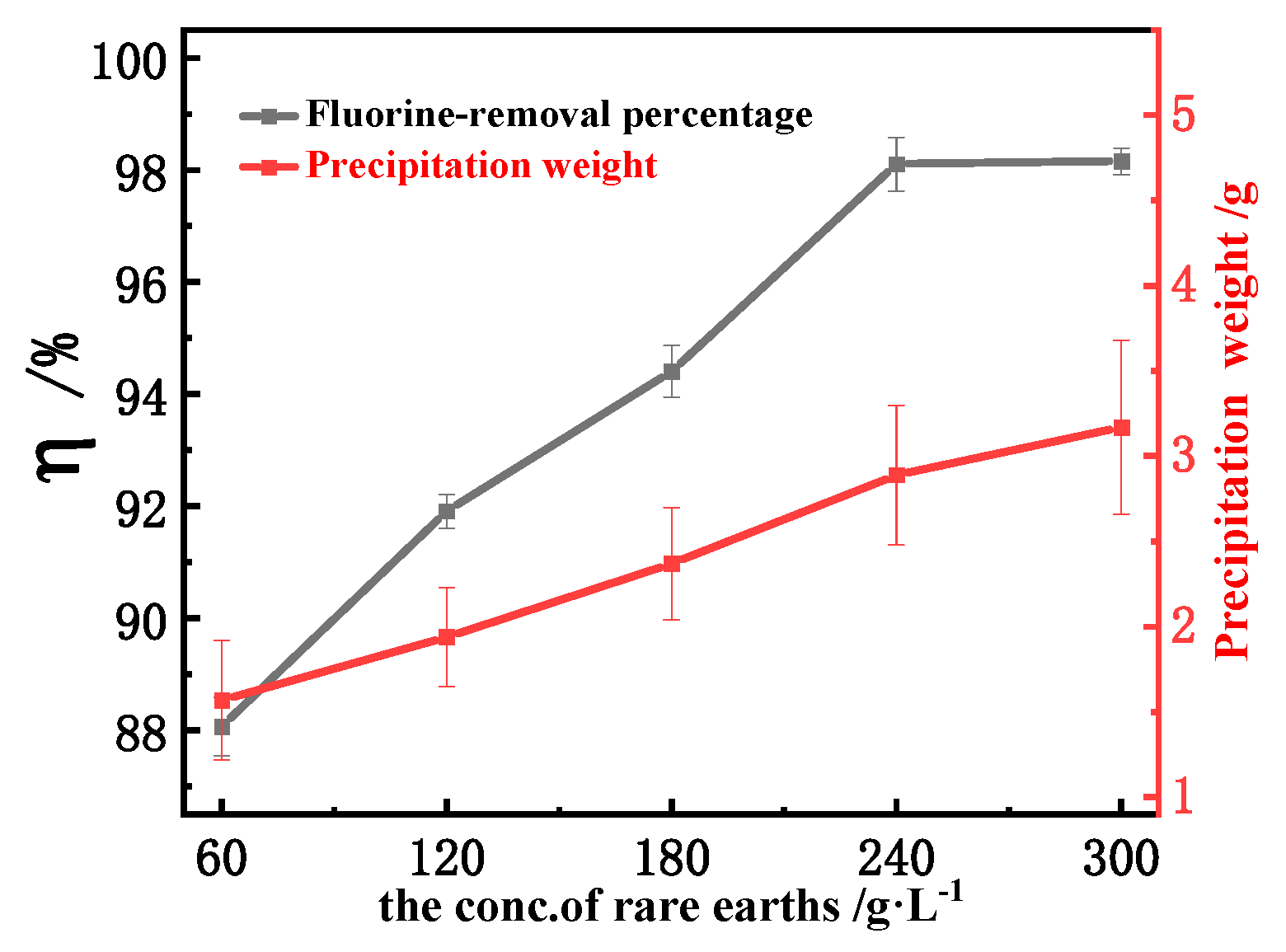
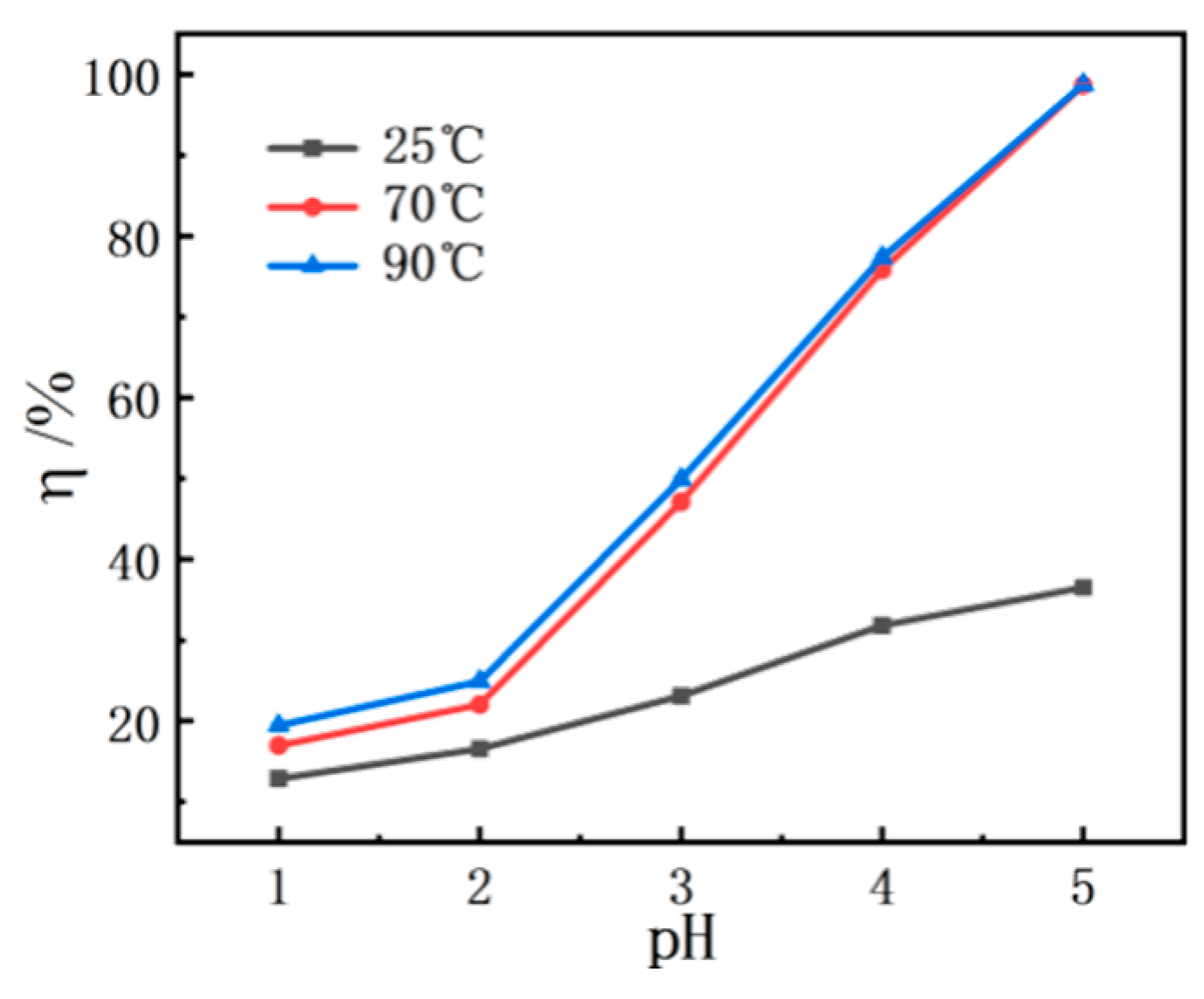
3.3.2. Conditional Experiment of Fluorine Removal by CO2 Precipitation

Figure 15 shows the effect of initial conc. of rare earths on fluorine removal. The results show that the fluorine-removal percentage increases with an increase in conc. of rare earths. Fluorine removal can reach 98.24% at a conc. of rare earths of 240 g/L. With a further increase in the conc. of rare earths, the fluorine-removal percentage basically remains at about 98%. What is interesting is that when the conc. of rare earths increases from 240 g/L to 300 g/L, the amount of precipitated slag slightly increases from 2.89 g to 3.17 g. This amount of precipitated slag is lower than that when lanthanum carbonate is used as fluorine-removal agent. Therefore, the optimal initial rare earth concentration should be considered to be 240–300 g/L.
Figure 16 shows the effects of different temperatures and initial pH on fluorine removal by CO2 precipitation. Temperatures of 25 °C, 70 °C and 90 °C were selected and the initial pH was adjusted by ammonia water. It can be seen that the fluorine-removal percentage gradually increases with an increase in initial pH and reaction temperature. This is because the content of OH in the solution increases with an increase in the initial pH, which is conducive to the reaction of CO2 and OH to produce carbonate CO32−, thus promoting the formation of rare earth carbonate compounds. In addition, an increase in temperature provides energy for the molecules in the solution and accelerates the movement rate of the molecules, which increases the number of molecular collisions of the reactants per unit time and further promotes the formation of rare earth carbonate compounds. At the same time, higher pH values and temperatures are conducive to the adsorption of F and accelerate the exchange of ions, which further promotes the formation of REFCO3 precipitation. The fluorine-removal percentage can reach 98.65% under initial pH of 5 and a temperature of 70 °C. When the temperature is raised to 90 °C, the fluorine-removal percentage is basically the same as at 70 °C, so the best fluorine removal temperature is 70 °C, and the best initial pH is 5.
Figure 17 describes the effect of reaction time and stirring speed on fluorine removal. First of all, the fluorine-removal percentage increases with an increase in reaction time because the formation of precipitated slag REFCO3 is a slow process of crystallization and aging. The removal percentage of fluorine can reach 98.37% at a reaction time of 1.5 h, which meets the requirement of low fluorine-extraction-index value. Secondly, CO2 gas is injected into the solution to facilitate mixing and stirring. Beyond that, effusion of the venturi jet disperses CO2 gas in the whole reaction system in the form of dispersing bubbles, increasing the gas-liquid-solid contact area, thus promoting the reaction rate, reaction mass transfer and heat transfer. Therefore, a high fluorine-removal percentage was reached in the absence of mechanical stirring. In addition, it was found that the fluorine-removal percentage decreased with an increase in mechanical stirring speed, which was mainly because mechanical stirring had adverse effects on the nucleation, crystallization and aging process of precipitated REFCO3. Secondly, mechanical stirring accelerates the escape velocity of CO2 gas in the solution and reduces the effective reaction efficiency. With an increase in stirring speed, a whirlpool appears in the center of the solution, which further reduces the contact time between CO2 gas and the solution. Therefore, this process does not require increased mechanical mixing.
Through the exploration of the above series of experimental conditions, the fluorine-removal percentage of the CO2 precipitation method can reach 98.92% under the following conditions: venturi injection, CO2 injection flow of 1000 L/h; reaction temperature, 70 °C; reaction pH, 5; initial conc. of rare earths, 240–300 g/L; reaction time, 1.5 h; no stirring. Following the optimal CO2 precipitation process, the volume of the MRECS also changes to 1.05 L and the pH changes to 5. The amount of fluorine precipitated slag obtained can also be returned to the alkali decomposition process. The contents of rare earth and fluorine in the final MRECS are shown in Table 5.
To sum up, the above two methods effectively realized removal of fluorine in the mixed fluorine-bearing rare earth chloride solution by exchanging different ionic groups. The mechanism of the reaction is shown in Figure 18. Both methods can meet the requirements of the extraction process, and no other impurities are added to the MRECS. The obtained RECO3(OH), REFCO3, and RE2O2CO3 precipitated slags are rare earth compounds, which can be returned to the original process and effectively recover the rare earth and fluorine. Therefore, both methods belong to high-efficiency and green processes and have certain prospective practical applications.
In order to directly apply the rare earth chloride solution after fluorine removal as raw material in the existing extraction industrial production line and under the premise of considering efficiency and cost, we can refer to the fluorine content index of rare earth chloride solution obtained by the concentrated sulfuric-acid process, namely when the rare earth concentration of rare earth chloride solution is 330 g/L and the fluorine content is less than 0.03 g/L. Since the concentration of rare earth chloride solution in industrial production will change to around 300 g/L, the fluorine content in rare earth chloride solution can be expressed by the ratio of the mass of rare earth oxide to the mass of fluorine. That is, when the mass ratio of rare earth oxide to fluorine is greater than 1.1 × 10⁴, the rare earth chloride solution can be applied to the existing industrial extraction production line. In actual production, we can choose the best index with the most economic benefit according to this dynamic index.
In addition, according to the wastewater discharge index in the national standard of the People’s Republic of China -Emission standards for pollutants from rare earth industry [37], the fluorine content in wastewater produced by the rare earth industry should be less than 5 mg/L. In order to meet this index and reduce environmental pollution in subsequent processes, lower fluorine content can be used as the optimal index, which is more conducive to environmental protection and fluorine-resource recovery.

4. Conclusions

First, the effect of different rare earth compounds as fluorine-removal agents on the fluorine-bearing mixed rare earth chloride solution was studied. The results showed that the fluorine-removal effect of lanthanum carbonate and cerium carbonate was better than that of lanthanum oxide and lanthanum hydroxide. RECO3(OH) with porous structure was generated with rare earth carbonate as a fluorine-removal agent, which had a strong adsorption effect on F. Then, the adsorbed F replaced OH on the RECO3(OH) surface by ion exchange, finally forming REFCO3 precipitate. Therefore, F was removed by means of regenerating REFCO3 precipitate after adsorption. The experimental results show that the fluorine-removal percentage of rare earth chloride solution can reach 99.60% under the following conditions: lanthanum carbonate, 8%; initial conc. of rare earths, 240 g/L, initial solution pH ≤ 1; reaction temperature, 90 °C; reaction time, 2 h. Secondly, the process of fluorine removal by CO2 precipitation was studied. CO32− formed in mixed rare-earth chloride solution after injection of CO2 gas, and then CO32− was combined with RE3+ to form RE2(CO3)3. At the same time, F in the solution was adsorbed by RE2(CO3)3, replacing CO32− on the surface of RE2(CO3)3 by ion exchange. Finally, REFCO3 was generated. The experimental results show that the fluorine-removal percentage can reach 98.92% under the following conditions: venturi injection; CO2 dosage, 1000 L/h; reaction temperature, 70 °C; reaction pH, 5; initial conc. of rare earths, 240–300 g/L; reaction time, 1.5 h; no stirring. The efficient removal of fluorine in the fluorine-bearing mixed rare earth chloride solution was achieved by the exchange of different ionic groups. The results allow the adverse effects of fluorine on the subsequent extraction and separation of mixed rare earth chloride solution to be avoided. This technology has important practical significance for further development of the rare earth metallurgy industry, as well as environmental protection.

Author Contributions

Conceptualization, D.Z. and K.G.; data curation, D.Z.; formal analysis, D.Z., K.G., X.Z. and M.W.; funding acquisition, X.Z. and M.W.; investigation, D.Z. and K.G.; methodology, D.Z. and K.G.; project administration, D.Z. and M.W.; validation, D.Z., K.G., X.Z. and M.W.; visualization, D.Z.; writing–original draft, D.Z.; writing–review and editing, D.Z. All authors have read and agreed to the published version of the manuscript.

Funding

This research was funded by the Project supported by the National Natural Science Foundation of China (51964040, 51564042, 51974168, 51662033), the B Program of Inner Mongolia Youth Science and Technology Talents (NJYT-19-B27) and the State Key Laboratory of Silicate Materials for Architectures (Wuhan University of Technology) (SYSJJ2020-08). And The APC was funded by the National Natural Science Foundation of China (51974168).

Institutional Review Board Statement

Not applicable.

Informed Consent Statement

Not applicable.

Data Availability Statement

Not applicable.

Acknowledgments

This work was supported by the Project supported by the National Natural Science Foundation of China (51964040, 51564042, 51974168, 51662033), the B Program of Inner Mongolia Youth Science and Technology Talents (NJYT-19-B27) and the State Key Laboratory of Silicate Materials for Architectures (Wuhan University of Technology) (SYSJJ2020-08).

Conflicts of Interest

The authors declare no conflict of interest.

Abbreviations

The following abbreviations are used in this manuscript:
RECl3Mixed rare earth chloride solution
REORare earth oxide
MRECMixed rare earth concentrates
MRECSMixed rare earth chloride solution
Conc.Concentration

References

  1. Suli, L.M.; Ibrahim, W.H.W.; Aziz, B.A.; Ismail, M. A Review of Rare Earth Mineral Processing Technology. Chem. Eng. Res. Bull. 2017, 19, 20–35. [Google Scholar] [CrossRef] [Green Version]
  2. Wang, Z.Y.; Fan, H.R.; Zhou, L.L.; Yang, K.F. Carbonatite-Related REE Deposits: An Overview. Minerals 2020, 10, 965. [Google Scholar] [CrossRef]
  3. Zou, D.; Chen, J.; Cui, H.M.; Liu, Y.; Li, D.Q. Wet Air Oxidation and Kinetics of Cerium (IIl) of Rare Earth Hydroxides. Ind. Eng. Chem. Res. 2014, 53, 13790–13796. [Google Scholar] [CrossRef]
  4. Zhao, J.M.; Pan, F.; Liu, H.Z. An environmentally friendly Na2CO3-roasting decomposition strategy for the mixed rare earth concentrate. Sep. Purif. Technol. 2016, 168, 161–167. [Google Scholar] [CrossRef]
  5. Li, M.; Gao, K.; Zhang, D.L.; Duan, H.J.; Ma, L.L. The influence of temperature on rare earth flotation with naphthyl hydroxamic acid. J. Rare Earths 2018, 36, 99–107. [Google Scholar] [CrossRef]
  6. Huang, X.W.; Long, Z.Q.; Wang, L.S.; Feng, Z.Y. Technology development for rare earth cleaner hydrometallurgy in China. Rare Met. 2015, 34, 215–222. [Google Scholar] [CrossRef]
  7. Chen, S.L.; Feng, Z.Y.; Wang, M.; Zhao, L.S.; Yu, Z.H.; Xia, C.; Huang, X.W. Leaching kinetic study of sulfuric acid roasted mixed-type rare earth concentrate for reducing the solid-waste production and chemical consumption. J. Clean. Prod. 2020, 260, 120989. [Google Scholar] [CrossRef]
  8. Wu, W.W. Rare Earth Metallurgy; Chemical Industry Press: Beijing, China, 2005; pp. 10–11. [Google Scholar]
  9. Li, J.F.; Li, M.; Zhang, D.L.; Gao, K.; Xu, W.; Wang, H.H.; Geng, J.L.; Ma, X.F.; Huang, L. Clean production technology of selective decomposition of Bayan Obo rare earth concentrate by NaOH. J. Clean. Prod. 2019, 236, 117616. [Google Scholar] [CrossRef]
  10. Li, J.L.; Li, M.; Zhang, D.L.; Gao, K.; Xu, W.; Wang, H.H.; Geng, J.L.; Huang, L. Clean Production Technology of Baiyun Obo Rare Earth Concentrate Decomposed by Al(OH)3-NaOH. Chem. Eng. J. 2020, 382, 122790. [Google Scholar] [CrossRef]
  11. Li, M.; Li, J.F.; Zhang, D.L.; Gao, K.; Wang, H.H.; Xu, W.; Geng, J.L.; Zhang, X.Y.; Ma, X.F. Decomposition of mixed rare earth concentrate by NaOH roasting and kinetics of hydrochloric acid leaching process. J. Rare Earths 2020, 38, 1019–1029. [Google Scholar] [CrossRef]
  12. Li, M.; Zhang, D.L.; Yan, Y.J.; Gao, K.; Liu, X.Y.; Li, J.F. Effect of oxidation behavior of cerium during the roasting process on the leaching of mixed rare earth concentrate. Hydrometallurgy 2017, 174, 156–166. [Google Scholar] [CrossRef]
  13. Zhang, D.L.; Li, M.; Gao, K.; Li, J.F.; Yan, Y.J.; Liu, X.Y. Physical and chemical mechanism underlying ultrasonically enhanced hydrochloric acid leaching of non-oxidative roasting of bastnaesite. Ultrason. Sonochem. 2017, 39, 774–781. [Google Scholar] [CrossRef] [PubMed]
  14. Sawant, R.M.; Rastogi, R.K.; Mahajan, M.A.; Chaudhuri, N.K. Stabilisation of tetravalent cerium in perchloric acid medium and measurement of the stability constants of its fluoride complexes using ion selective potentiometry. Talanta 1996, 43, 89–94. [Google Scholar] [CrossRef]
  15. Zhang, Z.F.; Li, H.F.; Guo, F.Q.; Meng, S.L.; Li, D.Q. Synergistic extraction and recovery of Cerium(IV) and Fluorine from sulfuric solutions with Cyanex 923 and di-2-ethylhexyl phosphoric acid. Sep. Purif. Technol. 2008, 63, 348–352. [Google Scholar] [CrossRef]
  16. Zhang, Z.F.; Gao, F.Q.; Meng, S.L.; Jia, Q.; Li, H.F.; Li, D.Q. Simultaneous Recovery of Cerium and Fluorine from Bastnaesite leach liquor by Mixtures of Cyanex 923 and HEH(EHP). Ind. Eng. Chem. Res. 2010, 49, 6184–6188. [Google Scholar] [CrossRef]
  17. Zuo, Y.; Liu, Y.; Chen, J.; Li, D.Q. Extraction and recovery of cerium (IV) along with fluorine(I) from bastnasite leaching liquor by DEHEHP in [C8mim]PF6. J. Chem. Technol. Biotechnol. 2009, 84, 949–956. [Google Scholar] [CrossRef]
  18. Wang, L.S.; Yu, Y.; Huang, X.W.; Long, Z.Q.; Cui, D.L. Toward greener comprehensive utilization of bastnaesite: Simultaneous recovery of cerium, fluorine, and thorium from bastnaesite leach liquor using HEH(EHP). Chem. Eng. J. 2013, 215–216, 162–167. [Google Scholar] [CrossRef]
  19. Rare Earth Industry Standard People’s Republic of China. Chemical Analysis Method of Rare Earths Fluoride. Determination of Fluorine Content. Water Vapor Distillation-EDTA Titration; Ministry of Industry and Information Technology, PRC Standards Press of China: Beijing, China, 2012; 155066.2-24644. XB/T 615-2012.
  20. Jin, Z.; Jia, Y.; Zhang, K.S.; Kong, L.T.; Sun, B.; Shen, W.; Meng, F.L.; Liu, J.H. Effective removal of fluoride by porous MgO nanoplates and its adsorption mechanism. J. Alloys Compd. 2016, 675, 292–300. [Google Scholar] [CrossRef]
  21. Kim, P.; Anderko, A.; Navrotsky, A.; Riman, R.E. Trends in Structure and Thermodynamic Properties of Normal Rare Earth Carbonates and Rare Earth Hydroxycarbonates. Minerals 2018, 8, 106. [Google Scholar] [CrossRef] [Green Version]
  22. Li, L.C. Extraction and Separation of Rare Earth; Inner Mongolia Science and Technology Press: Inner Mongolia, China, 2011; pp. 458–459. [Google Scholar]
  23. Wu, H.X.; Wang, T.J.; Dou, X.M.; Zhao, B.; Chen, L.; Jin, Y. Spray Coating of Adsorbent with Polymer Latex on Sand Particles for Fluoride Removal in Drinking Water. Ind. Eng. Chem. Res. 2008, 47, 4697–4702. [Google Scholar] [CrossRef]
  24. He, J.G.; Li, Y.; Xue, X.X.; Ru, H.Q.; Huang, X.W.; Yang, H. Separation of fluorine/cerium from fluorine-bearing rare earth sulfate solution by selective adsorption using hydrous zirconium oxide. RSC Adv. 2016, 6, 43814–43822. [Google Scholar] [CrossRef]
  25. Haschke, J.M. The lanthanum hydroxide fluoride carbonate system: The preparation of synthetic bastnaesite. J. Solid-State Chem. 1975, 12, 115–121. [Google Scholar] [CrossRef] [Green Version]
  26. Zhang, Y.X.; Jia, Y. Fluoride adsorption on manganese carbonate: Ion-exchange based on the surface carbonate-like groups and hydroxyl groups. J. Colloid Interface Sci. 2018, 510, 407–417. [Google Scholar] [CrossRef] [PubMed]
  27. Wu, H.J.; Zhang, H.L.; Yang, Q.X.; Wang, D.S.; Zhang, W.J.; Yang, X.F. Calcined Chitosan-Supported Layered Double Hydroxides: An Efficient and Recyclable Adsorbent for the Removal of Fluoride from an Aqueous Solution. Materials 2017, 10, 1320. [Google Scholar] [CrossRef] [Green Version]
  28. Mirna, H.S.; Maja, E.R.; Andrew, F. A Review on Adsorption of Fluoride from Aqueous Solution. Materials 2014, 7, 6317–6366. [Google Scholar]
  29. Zhang, K.S.; Wu, S.B.; Wang, X.L.; He, J.Y.; Sun, B.; Jia, H.; Luo, T.; Meng, F.L.; Jin, Z.; Lin, D.Y.; et al. Wide pH range forfluoride removal from water by MHS-MgO/MgCO3 adsorbent: Kinetic, thermodynamic and mechanism studies. J. Colloid Interface Sci. 2015, 446, 194–202. [Google Scholar] [CrossRef]
  30. Liu, X.; Zhou, F.; Chi, R.; Feng, J.; Ding, Y.Y.; Liu, Q. Preparation of Modifified Montmorillonite and Its Application to Rare Earth Adsorption. Minerals 2019, 9, 747. [Google Scholar] [CrossRef] [Green Version]
  31. Yin, J.; Zou, Z.; Tian, J. Preparation of crystalline rare earth carbonates with large particlesize from the lixivium of weathered crust elution-deposited rare earth ores. Int. J. Miner. Metall. Mater. 2020, 27, 1482–1488. [Google Scholar] [CrossRef]
  32. Jin, L.; Zhang, Y.; Dombrowski, J.; Chen, C.; Pravatas, A.; Xu, L.; Perkins, C.; Suib, S. ZnO/La2O2CO3 layered composite: A new heterogeneous catalyst for the efficient ultra-fast microwave biofuel production. Appl. Catal. B Environ. 2011, 103, 200–205. [Google Scholar] [CrossRef]
  33. Teng, S.X.; Wang, S.G.; Gong, W.X.; Liu, X.W.; Gao, B.Y. Removal of fluoride by hydrous manganese oxide-coated alumina: Performance and mechanism. J. Hazard. Mater. 2009, 168, 1004–1011. [Google Scholar] [CrossRef]
  34. Bhatnagar, A.; Kumar, E.; Sillanp, M. Fluoride removal from water by adsorption—A review. Chem. Eng. J. 2011, 171, 811–840. [Google Scholar] [CrossRef]
  35. Kenneth, N.H. Characteristics of Precipitation of Rare Earth Elements with Various Precipitants. Minerals 2020, 10, 178. [Google Scholar]
  36. Wei, F.; Cao, C.Y.; Huang, P.P.; Song, W.G. A new ion exchange adsorption mechanism between carbonate groups and fluoride ions of basic aluminum carbonate nanospheres. RSC Adv. 2015, 5, 13256–13260. [Google Scholar] [CrossRef]
  37. GB 26451-2011; Emission Standards for Pollutants from Rare Earth Industry; China Environmental Science Press: Beijing, China, 2011.
Figure 1. Schematic flow chart of the acid-leaching alkali-solution process.
Minerals 12 00031 g001
Figure 2. Schematic diagram of experimental process. (A) Rare earth compound as fluorine-removal agent, (B) CO2 precipitation.
Minerals 12 00031 g002
Figure 3. Methods of CO2 injection: (A) direct injection, (B) venturi injection.
Minerals 12 00031 g003
Figure 4. Effect of the dosage of fluorine-removal agent and reaction temperature on the fluorine-removal percentage. (a) Lanthanum oxide and lanthanum hydroxide (b) lanthanum carbonate and cerium carbonate, initial conc. of rare earths: 240 g/L, time: 2 h, initial pH: 1.
Minerals 12 00031 g004
Figure 5. Effect of CO2 injection flow rate on fluorine-removal percentage. Initial conc. of rare earth, 240 g/L; reaction time, 1.5 h; initial pH, 5; temperature, 70 °C.
Minerals 12 00031 g005
Figure 6. XRD patterns of filter residues after the fluorine-removal experiment.
Minerals 12 00031 g006
Figure 7. (a,b) Shows the SEM of the precipitated slag obtained by lanthanum oxide as a fluorine removal agent, and the EDS of filter residue: (1)–(3) RECl3•nH2O. (4) CaCl2•nH2O.
Minerals 12 00031 g007
Figure 8. (a,b) Shows the SEM of the precipitated slag obtained by lanthanum hydroxide as a fluorine removal agent, and the EDS of filter residue: (1)–(3) RECl3•nH2O. (4) CaCl2•nH2O.
Minerals 12 00031 g008
Figure 9. (a,b) Shows the SEM of the precipitated slag obtained by cerium carbonate as a fluorine removal agent, and the EDS of filter residue: (1) RECO3(OH), REFCO3; (2) RECl3 × nH2O.
Minerals 12 00031 g009
Figure 10. (a,b) Shows the SEM of the precipitated slag obtained by Lanthanum carbonate as a fluorine removal agent, and the EDS of filter residue: (1) RECO3(OH), REFCO3; (2) RECl3 × nH2O.
Minerals 12 00031 g010
Figure 11. XRD patterns of filter residues obtained with fluorine removal by CO2 precipitation.
Minerals 12 00031 g011
Figure 12. (a,b) Shows the SEM of the precipitated slag obtained by CO2 as a fluorine removal agent, and the EDS of filter residue: (1,3) REFCO3. (2) RE2O2CO3.
Minerals 12 00031 g012
Figure 13. Effect of initial conc. of rare earths on fluorine-removal percentage and precipitation weight (lanthanum carbonate, 8%; initial pH, 1; temperature, 90 °C; time, 2 h).
Minerals 12 00031 g013
Figure 14. Effect of initial pH and reaction time on fluorine-removal percentage (initial conc. of rare earths, 240 g/L; lanthanum carbonate, 8%; temperature, 90 °C).
Minerals 12 00031 g014
Figure 15. Effect of initial conc. of rare earths on fluorine removal by CO2 precipitation (initial pH, 5; time, 1.5 h; temperature: 70 °C).
Minerals 12 00031 g015
Figure 16. Effect of initial pH and temperature on fluorine removal by CO2 precipitation (initial conc. of rare earths, 240 g/L; time, 1.5 h; temperature, 25 °C, 70 °C, 90 °C).
Minerals 12 00031 g016
Figure 17. Effect of reaction time and stirring speed on fluorine removal by CO2 precipitation (initial conc. of rare earths, 240 g/L; initial pH, 5; temperature, 70 °C).
Minerals 12 00031 g017
Figure 18. Schematic diagram of lanthanum carbonate or CO2 fluorine-removal reaction mechanism.
Minerals 12 00031 g018
Table 1. Chemical composition of mixed rare earth concentrate (wt%).
REOFP2O5CaOTFeSiO2BaO
66.317.953.563.011.380.920.43
SThO2MgONb2O5K2OAl2O3Sc2O3
0.320.260.170.050.040.067.1 × 10−3
Table 2. Rare earth partitioning of mixed rare earth concentrate (%).
Y2O3La2O3CeO2Pr6O11Nd2O3Sm2O3Eu2O3Gd2O3
0.2328.3050.774.7814.010.970.180.34
Tb4O7Dy2O3Er2O3Tm2O3Yb2O3Lu2O3Ho2O3-
<0.100.12<0.10<0.10<0.10<0.10<0.10-
Table 3. The main composition of mixed rare earth chloride solution (g/L).
REOFP2O5CaOMgOMnO2TFe
282.310.570.022.840.830.120.02
BaOSiO2SO42−ZnOAl2O3ThO2-
0.010.020.509.76 × 10−33.57 × 10−30.01 × 10−3-
Table 4. The main composition of the MRECS after fluorine removal (g/L).
REOFP2O5CaOMgOMnO2TFe
281.252.17 × 10−40.021.580.570.080.02
Table 5. The main composition of the MRECS after fluorine removal by CO2 precipitation (g/L).
REOFP2O5CaOMgOMnO2TFe
270.365.86 × 10−30.022.420.650.080.02
Publisher’s Note: MDPI stays neutral with regard to jurisdictional claims in published maps and institutional affiliations.

