1. Introduction
The most widely advocated method for disposal of low and intermediate-level nuclear waste is deep geological disposal. A geological repository is supposed to be constructed at a significant depth below the surface and the potential site should fulfill several criteria, which include low permeability, adequate strength, and the long-term stability of the host rock. The repository uses multiple natural and engineered barriers that include the container, sealing materials, and the host rock. The repository design concepts differ between different countries. The main host rocks considered are igneous crystalline rocks, argillaceous clay rocks, and salts. The choice of host rock is mainly governed by the availability of suitable geological formations of adequate thickness and geological setting.
Deep geological storage is being considered in most countries with nuclear power production. In Switzerland, an active site-selection process is currently underway. The site selections for France and Sweden have already been made and, in Sweden, a nuclear regulatory body is currently reviewing a license application for construction. The first project to enter the construction phase is Finland’s Onkalo spent nuclear fuel repository, which obtained regulatory approval in 2015.
In order to build confidence in deep geological disposal technologies, several Underground Research Laboratories (URL) have been constructed. Those include generic URLs built for research and testing purposes (e.g., Mount Terri URL in Switzerland, Tournemire facility in France, Aspo Hard Rock Lab in Sweden) as well as site-specific URLs (e.g., Meuse/Haute Marne URL in France, Onkalo URL in Finland, Gorleben URL in Germany). The subsurface testing allows not only for an in-depth investigation of the selected geological environment but also provides an opportunity for verification of different methodologies for simulating the mechanical response of the host rock.
Canadian efforts are currently directed at two potential sites, i.e., Bruce County and Ignace area in Ontario. The Bruce site has a sedimentary rock formation (Cobourg limestone of the Michigan Basin), while the Ignace site includes a crystalline rock of the Canadian Shield. In mechanical terms, these two types of rocks have high strength, low permeability, and high sorption capacity, so that they would constitute an efficient barrier to radionuclide migration.
Most sedimentary rocks are inherently anisotropic and often heterogeneous (e.g., [
1,
2]). Anisotropy is due to stratification resulting from the sedimentation process; heterogeneity, on the other hand, originates from the interspersed fabric (cf. [
3,
4]). For crystalline rocks, layering takes a less prominent role. Thus, the intact rock may be perceived as isotropic in terms of both mechanical and hydraulic properties (e.g., [
2,
5,
6]). The deformation process is characterized by the onset of microcracks, which progressively increase in density, ultimately coalescing and leading to strain localization at the macroscale. As a result, in crystalline rocks fractures are ubiquitous and the fracture systems exhibit a range of anti-clustered to clustered patterns. The nature and evolution of fracture systems directly influence the strength, geophysical, and fluid transport characteristics. Therefore, the main challenge in terms of modeling the behavior of crystalline rocks is the assessment of hydromechanical properties in the presence of pre-existing and newly forming discontinuities.
The onset of localization is typically considered as a bifurcation problem [
7]. Alternatively, in tension regime, some simple path-independent strength criteria are invoked [
8]. The localized zones exhibit strain-softening which, for classical continuum representations, leads to ill-posedness of the initial boundary-value problem [
9]. The latter results in a pathological mesh-dependency of the numerical solution. In order to remedy the problem, the classical framework needs to be enriched by incorporating an internal length scale parameter. Common approaches include non-local theories [
10,
11] as well as Extended Finite Element Method (XFEM) (cf. [
12,
13]). Both these approaches have limitations that stem either from ambiguity in defining the notion of internal length or, like in the case of XFEM, computational inefficiency resulting from the incorporation of additional degrees of freedom that account for the presence of discontinuities.
The work presented here is focused on the description of hydromechanical coupling associated with the onset and propagation of localized damage. The mathematical framework incorporates an embedded discontinuity approach, which employs volume averaging in order to define representative homogenized properties. The formulation addresses both the assessment of equivalent permeability in the region intercepted by a fracture and the associated interaction with the mechanical response in the presence of discontinuities. In particular, the effect of the progressive evolution of damage on the hydro-mechanical coupling is examined. The framework is verified by a numerical example that involves 3D simulation of an axial splitting test carried out on a saturated sample under external control of fluid pressure.
2. Governing Equations of Hydromechanical Coupling under Homogeneous and Localized Deformation
Consider an initial-boundary-value problem involving a saturated porous medium undergoing deformation coupled with a transient flow. Denote the spatial domain and its external boundary as
and
, respectively, where
stands for the spatial dimension of the problem. Furthermore, let
be the time interval, such that
, and let
comprise of nonoverlapping Dirichlet (
and
) and Neumann boundaries (
and
). Restricting the considerations to static regime and assuming infinitesimal deformations, the field equations can be stated as (cf. [
14])
subject to
In equations above,
is the unit outward normal to
,
is the Biot coefficient,
is defined as
, where
and
are the porosity and the bulk modulus of fluid, respectively,
represents the density of mixture, while
is gravitational acceleration. Moreover,
and
denote the spatial gradient and divergence operators,
is the permeability tensor,
is the dynamic viscosity of the fluid,
is the pore–fluid pressure, while
and
are the effective Cauchy stress tensor and the solid’s displacement vector, respectively.
It is noted that the balance equations explicitly incorporate Darcy’s law for the superficial velocity as well as the effective stress principle. The validity of Equation (2) is restricted to the case when the process is isothermal and there is no mass exchange between the solid and fluid phases. For small deformations, the mechanical power conjugate pair includes the effective stress () and the infinitesimal strain rate () tensors. Furthermore, the hydraulic power conjugate pair is the pore–fluid pressure () and the Darcy’s velocity ().
The homogenous deformation process may be described using a classical continuum representation. A common approach involves a standard rate-independent elastoplastic idealization, i.e.,
where
and
are the yield and potential functions, respectively,
and
are the fourth-order elastic and elastoplastic tangent moduli,
represents the plastic hardening modulus,
is the stress–space gradient operator, and
and
denote the dyadic product and double contraction between two tensors, respectively. Apparently, for an elastic material, there is
.
In geomaterials, in particular in sedimentary/crystalline rocks, the failure mode involves localized deformation. The latter is heterogeneous at the macroscale as it entails the development of high strain gradient zones, within which the mechanical response typically exhibits strain-softening. In this case, the standard continuum representation (4), which does not incorporate any internal length measure, leads to a systemic dependence of the numerical solution on the discretization. As mentioned earlier, in the last few decades different regularization techniques have been proposed to alleviate this problem, i.e., to restore the well-posedness of the governing equations. In this work, the framework incorporating a constitutive law with embedded discontinuity (CLED) is employed. The approach, which was originally developed in the early 1980s (cf. [
15]) and refined in the subsequent works [
16,
17], incorporates a ‘characteristic dimension’ associated with the presence of discontinuity. Most of the past developments dealt with the mechanical response of a single-phase solid and focused on modeling of discrete propagation of the damage in both brittle and frictional materials. Recently, the framework has been extended to include the description of hydro-mechanical interaction [
18]. The approach involves imposing a weak discontinuity in fluid pressure as well as a strong discontinuity in the displacement field within the considered referential volume. By enforcing admissible constraints in the flow regime and continuity of tractions in the fractured region, an equivalent permeability and a macroscopic stiffness operator are defined, both incorporating an internal length parameter. Within the CLED approach, the homogenized constitutive relations governing the hydromechanical response within the referential volume adjacent to the localized region, take the form (cf. [
18])
where
is the superficial (Darcy’s) velocity of the fluid and
and
denote the equivalent permeability and stress–strain tangent modulus tensors. The operators
and
are defined as
Here,
is the characteristic length defined as the ratio of the referential volume to the surface area of the discontinuity. Moreover,
is the unit normal to the discontinuity surface,
denotes the tangent modulus relating the rate of effective traction to velocity jump across the fractured region,
is the fourth-order identity tensor,
is the thickness of the localization zone,
and
denote the permeability tensors in the intact and localized domain, respectively, and
is an operator that defines the coefficients of the hydraulic constrains, viz.
where
and
are the unit vectors along the discontinuity surface.
Localization-Induced Permeability Evolution
According to Equation (6), the changes in thickness of the localized region do not directly affect the homogenized stress–strain tangent modulus since the expression is independent of it. At the same time, however, the evolution of thickness directly affects the homogenized permeability tensor Equation (7). Thus, there is an explicit coupling between the hydraulic and mechanical terms.
The change in equivalent permeability during the ongoing deformation is defined as
where
denotes the rate of the change of thickness, which represents the normal component of the velocity jump, i.e.,
Given the requirement of continuity of traction across the interface (cf. [
16]), there is
Substituting now Equation (11) into Equation (10) gives
Thus, by introducing Equation (12) in Equation (9), the following expression is obtained
where
is a fourth-order tensor relating the rates of permeability and strain, which is defined as
The evolution law Equation (13) governs the variation of equivalent permeability tensor during the deformation process associated with strain localization. It is evident that there is a direct coupling here, i.e., the change in the deformation field affects the permeability which, in turn, influences the velocity of flow and the generation of pore-fluid pressure.
In order to evaluate the term
, note that the permeability in the intact region (
) is independent of thickness
. Moreover, the normal component of permeability in the fractured zone, i.e., (
), is also independent of thickness. Thus, with reference to Equation (8), there is
Therefore, differentiating Equation (7), one obtains
In numerical implementation, it is convenient to refer the operator
to the local coordinate system
attached to the discontinuity surface. In this case, the matrix representation becomes
It can be shown that the above operator is symmetric in view of the symmetry of
. The individual components of this matrix may be expressed, after some algebraic transformations, in the form
It should be noted that in the expressions above,
is a diagonal operator, whose tangential components
and
are assumed to follow the local cubic law (cf. [
19]), i.e.,
. Therefore, in Equation (18), there is
.
Apparently, given the component form of
, this operator can be transformed into the global coordinate system by invoking the standard orthogonal transformation, i.e.,
where
is the transformation tensor whose components are the direction cosines of the base vectors of the local coordinate system.
3. Coupled Hydromechanical Analysis of an Axial Splitting Test
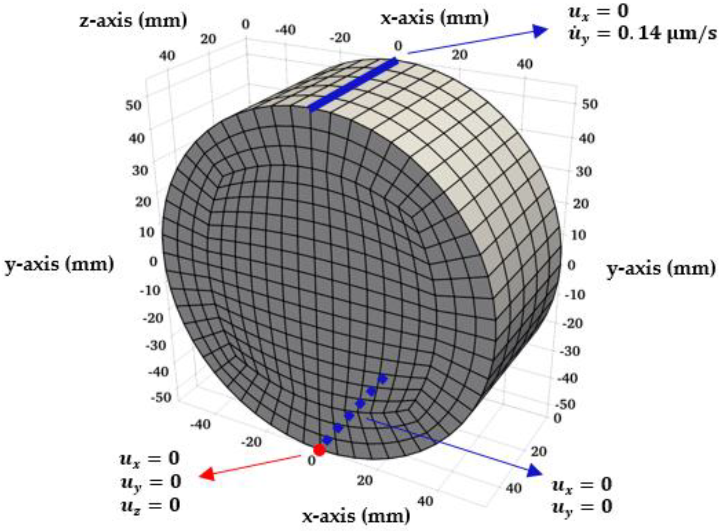
The numerical analysis presented here deals with the simulation of a tensile fracture in a splitting test conducted under fully saturated conditions. The coupled hydromechanical analysis is performed in 3D configuration and incorporates localization-induced permeability evolution. The finite element mesh contains trilinear isoparametric hexahedral elements for both the displacement and pressure fields (
Figure 1). The coupled FE formulation, which employs the embedded discontinuity approach, follows the framework outlined in Reference [
18]. The approach is enhanced by updating the permeability tensor in each loading step, cf. Equation (13), and incorporating a stabilization technique of Polynomial-Pressure-Projection (PPP) developed in Reference [
20]. The latter is required in the mixed
u–
p analysis of nearly incompressible (or a very low-permeability) porous media to avoid the loss of stability (cf. [
21]) when equal order interpolation functions are used for the field variables. The entire finite element code and the associated systems of linear algebraic equations were developed and solved in MATLAB R2020b.
In the analysis conducted here, the intact material is idealized as elastic-brittle. The onset of localization (tensile crack) is controlled by the maximum tensile strength (
) criterion, which stipulates that the macrocrack is perpendicular to the direction of the maximum tensile stress. In the post-localized regime, the strain-softening response along the discontinuity plane is described using a simple plasticity-based framework incorporating a degradation law for the tensile strength that is assumed to depend on the fracture energy (
). In particular, the yield function (
) in the localized region is taken in the form
where
is the effective traction vector. Following now the standard plasticity procedure, with
F described by Equation (20), the tangent stiffness operator
can be defined. The integration process employs the return-mapping scheme of Reference [
17], which is used for the stress update and the specification of the constitutive tensor (cf. Equation (6)) in the referential volume encompassing the localized region. The permeability tensor is then explicitly updated using representation (13).
The material properties, geometry, and boundary conditions are analogous to those in Reference [
22] and pertain to simulation of an axial splitting test conducted on saturated concrete specimen [
23]. The parameters used for the analysis are provided in
Table 1, where
,
,
, and
are Young’s modulus, Poisson’s ratio, tensile strength, and the fracture energy, respectively.
It should be noted that the test simulated here is not a standard Brazilian test. The experimental set-up and the testing protocol have been enhanced to examine the hydro-mechanical coupling and the evolution of permeability associated with the onset and propagation of localized damage [
23]. The cylindrical sample tested has a diameter of 110 mm and a thickness of 50 mm and is placed between upper and lower bearing plates. The lateral surface of the cylinder is assumed to be impermeable (i.e., no-flux boundary condition). The analysis has been conducted in two stages. In the first stage, a prescribed fluid pressure drop of 0.09 MPa is applied between the two faces of the cylinder. This pressure difference is maintained long enough until a steady-state condition is attained. Then, a prescribed displacement rate in the vertical y-direction is applied at the top of the cylinder (cf.
Figure 1).
The main results of the analysis are presented in
Figure 2,
Figure 3,
Figure 4,
Figure 5 and
Figure 6.
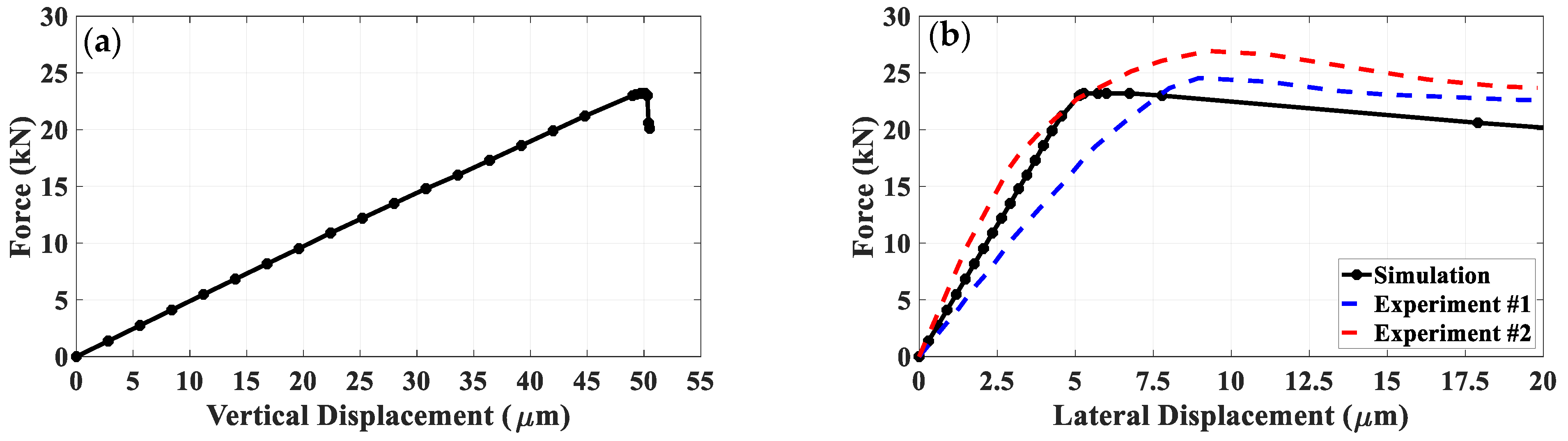
Figure 2a shows the variation of the resultant force with the applied vertical displacement. The ultimate load of
is reached at the vertical displacement of
, after which the predicted response is very brittle.
Figure 2b shows the corresponding evolution of lateral displacements, which was recorded experimentally. Note that two sets of data are provided here (after [
23]), which correspond to the same geometry and material type so that the difference indicates the actual scatter of the results. It is seen that both the predicted ultimate load, as well as the progressive increase in lateral displacements in the softening regime, are fairly consistent with the experimental data.
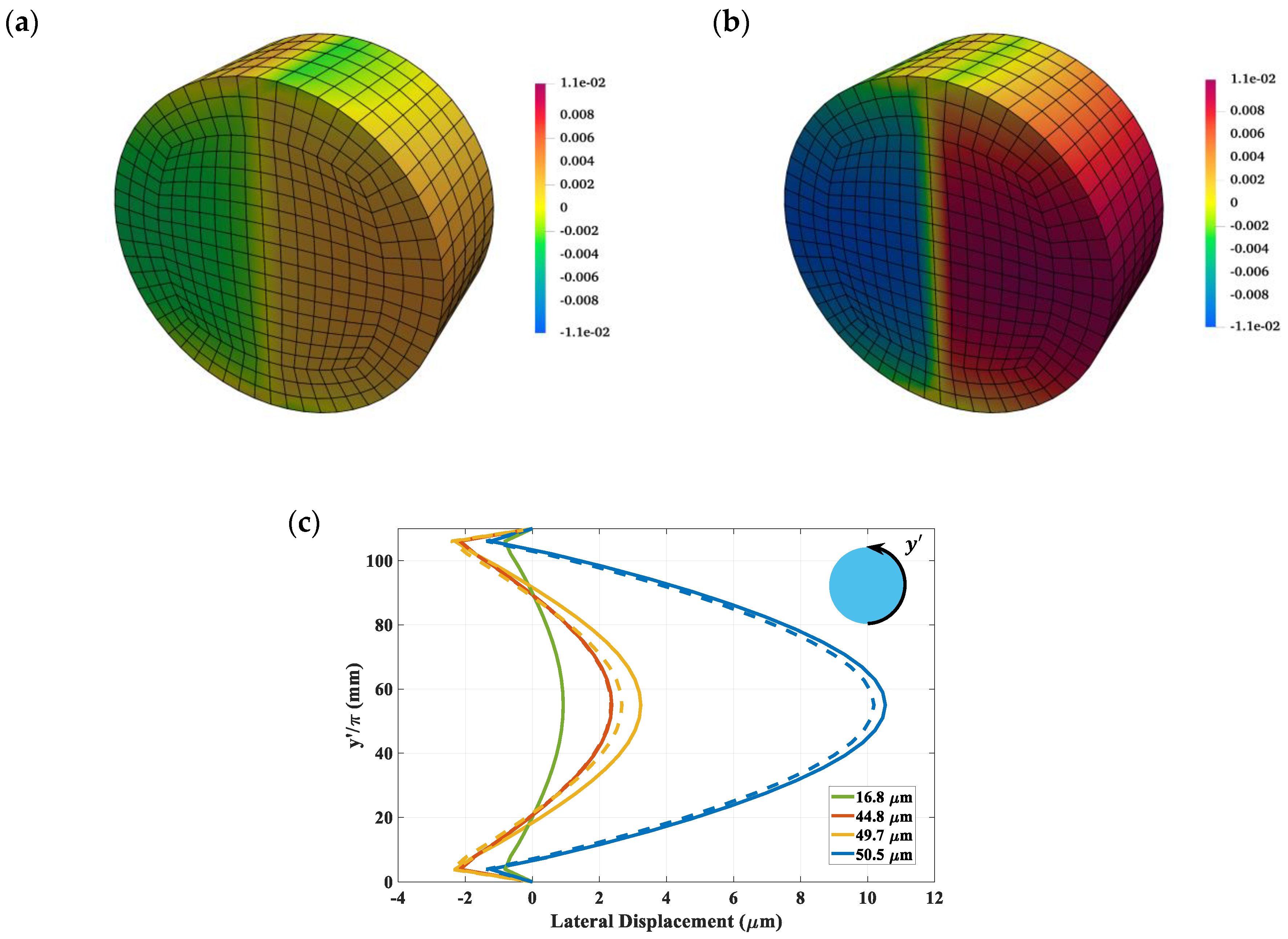
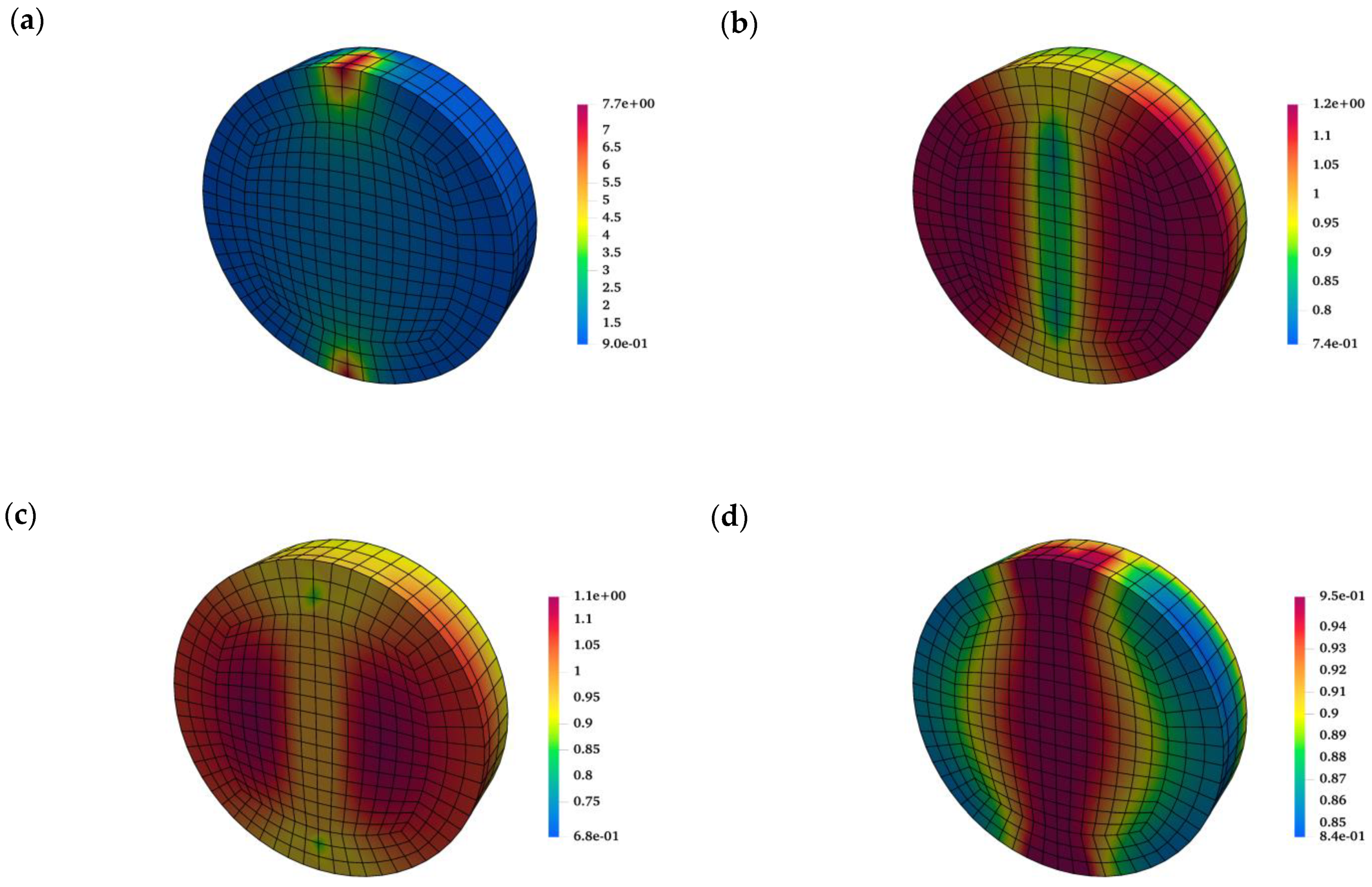
Figure 3a,b depicts the evolution of the horizontal displacement field at different load steps. It is evident here that at the advanced stages of loading the specimen tends to split into two halves, which is triggered by the localized nature of deformation. The results for the displacement field are supplemented by the lateral displacement profiles along the circumferential boundary of the specimen (
Figure 3c). It should be noted that these values are indicative of the crack opening, as the letter is the primary mechanism of deformation.
It should be mentioned that the analysis conducted here traced the crack propagation in a ‘smeared’ rather than discrete way (cf. [
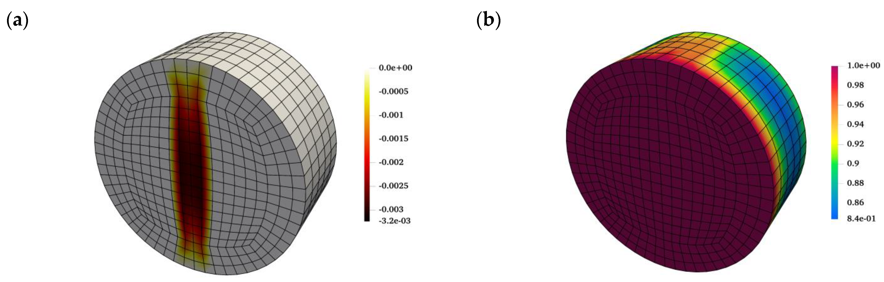
8]). For the given boundary conditions (i.e., concentrated load), the damage initiated in the region adjacent to load application and the tensile damaged zone was fully developed in the final stages of the analysis. The formation of this tensile crack, penetrating the entire sample, affects the permeability of the specimen, as the latter depends on the crack opening. This is evidenced in
Figure 4a, which depicts the distribution of the outflow flux. Clearly, the flow is contained to the fractured region and that through the intact domain is negligible. The outflow flux reaches a maximum value of
in the middle of the specimen, and progressively decreases along the height of the crack due to reduction of the aperture. The corresponding distribution of the pore-fluid pressure at the end of the analysis is shown in
Figure 4b.
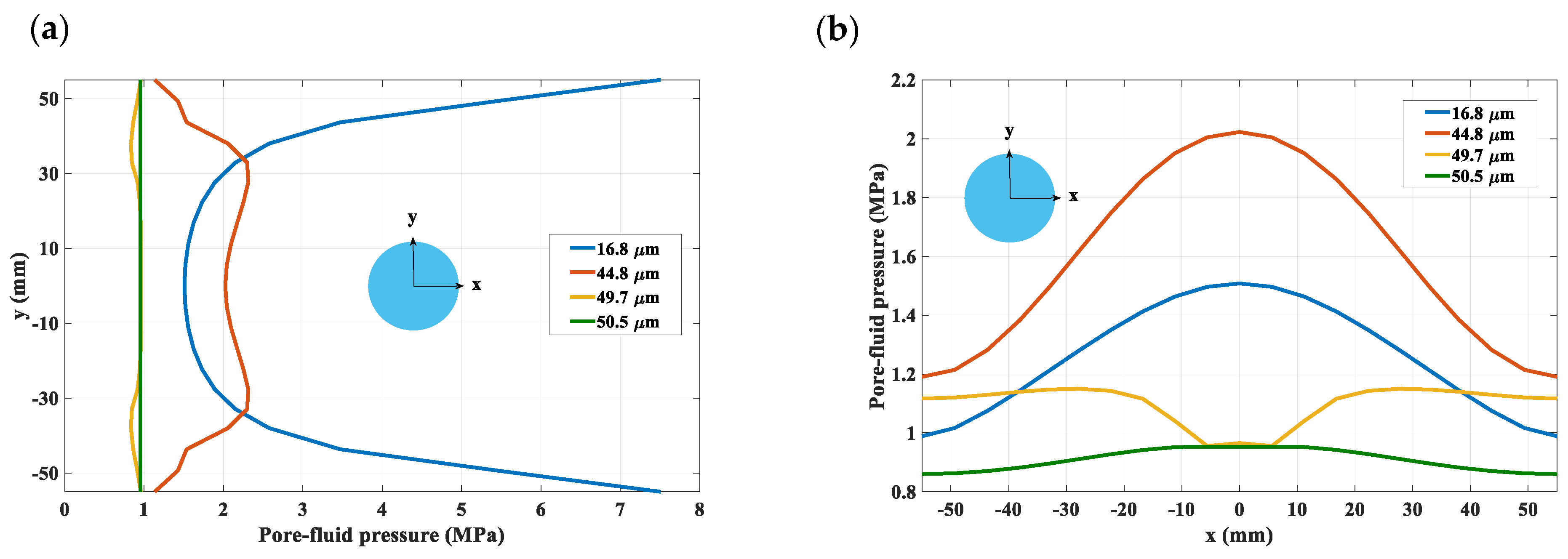
Finally,
Figure 5 and
Figure 6 present the evolution of the fluid pressure field in the vertical cut through the middle of the specimen. The contours in
Figure 5 depict the pore pressure distribution at different stages of loading and are supplemented by the profiles showing the variation along the center lines (
Figure 6). A non-monotonic rise in fluid pressure with time (i.e., the Mandel–Cryer effect) is captured here in the early stages of analysis, which is due to a very low permeability in the intact region (
Figure 5a). As the deformation progresses and the tensile cracks develop, the pore-fluid pressure decreases in the fractured regions due to the volume expansion (
Figure 5b–d). Moreover, in the softening regime, the dissipation of pore-fluid pressure is accelerated since the permeability in the cracked regions increases with the increase in the crack opening (cf.
Figure 5d and
Figure 6).
4. Discussion
Many types of rocks, especially crystalline rocks, are brittle and have very low permeability. Thus, prior to the onset of localized damage, their behavior, in fully saturated conditions, may be perceived as undrained. In the course of deformation, the microcracks develop and progressively increase in density, ultimately coalescing and leading to formation of macrocracks at the continuum level. These fractures create a preferred pathway for the transport of fluid. The propagation of macrocracks within the rock mass is associated with a strong coupling between the hydraulic and mechanical properties in both intact and fractured zones. The present paper is focused on describing this hydromechanical interaction using a volume averaging in the referential domain adjacent to the fracture. Such an approach for dealing with discontinuities is of considerable interest since it is computationally very efficient as compared to other commonly used techniques, like XFEM. Within the proposed framework, the equivalent permeability as well as the tangential stiffness operators both incorporate an internal length scale parameter. This ensures that the solution does not display a pathological sensitivity to FE discretization.
Hydromechanical analysis involving the propagation of localized damage in saturated porous media is a challenging task. In this case, the equivalent permeability operator depends on the aperture (opening) of the fracture and, at the same time, the crack opening evolves during the continuing deformation. In the research reported here, an evolution law was derived governing the variation of equivalent permeability with the macroscopic strain rates. The fully coupled formulation has been implemented in a finite element code developed in MATLAB R2020b and an illustrative example was provided involving a 3D simulation of an axial splitting test carried out on a saturated cylindrical sample. The results show that the load-vertical displacement characteristic displays an abrupt transition to brittle response after reaching the ultimate load, which is accompanied by the development of excessive lateral deformation. In the softening regime, an intense outflow flux is captured in the proximity of the localized regions triggered by the increase in permeability. Moreover, in the softening range, the pore-fluid pressure is rapidly dissipated because of the volume expansion of the solid matrix along with the evolving permeability in the cracked regions. The results, in terms of assessment of ultimate load, the fracture pattern and the fluid transmissivity are in fair agreement with the experimental data, thus providing a proof of concept in terms of the feasibility of the proposed approach. It should be noted that in the numerical simulations presented here, no special algorithm for the crack tracing was employed and, as a result, the cracks appear as smeared over a narrow region. While this has no visible impact on the predicted ultimate load [
24], it does not give a very accurate representation of the crack pattern. The discrete tracing can be incorporated into the present framework using a numerical scheme described in Reference [
8]. The latter, however, has only been employed for 2D applications so far and would need to be extended for a 3D geometry.


