
Separation and Stabilization of Arsenic from Lead Slime by the Combination of Acid Leaching and Forming Scorodite

Abstract
:1. Introduction
2. Experimental
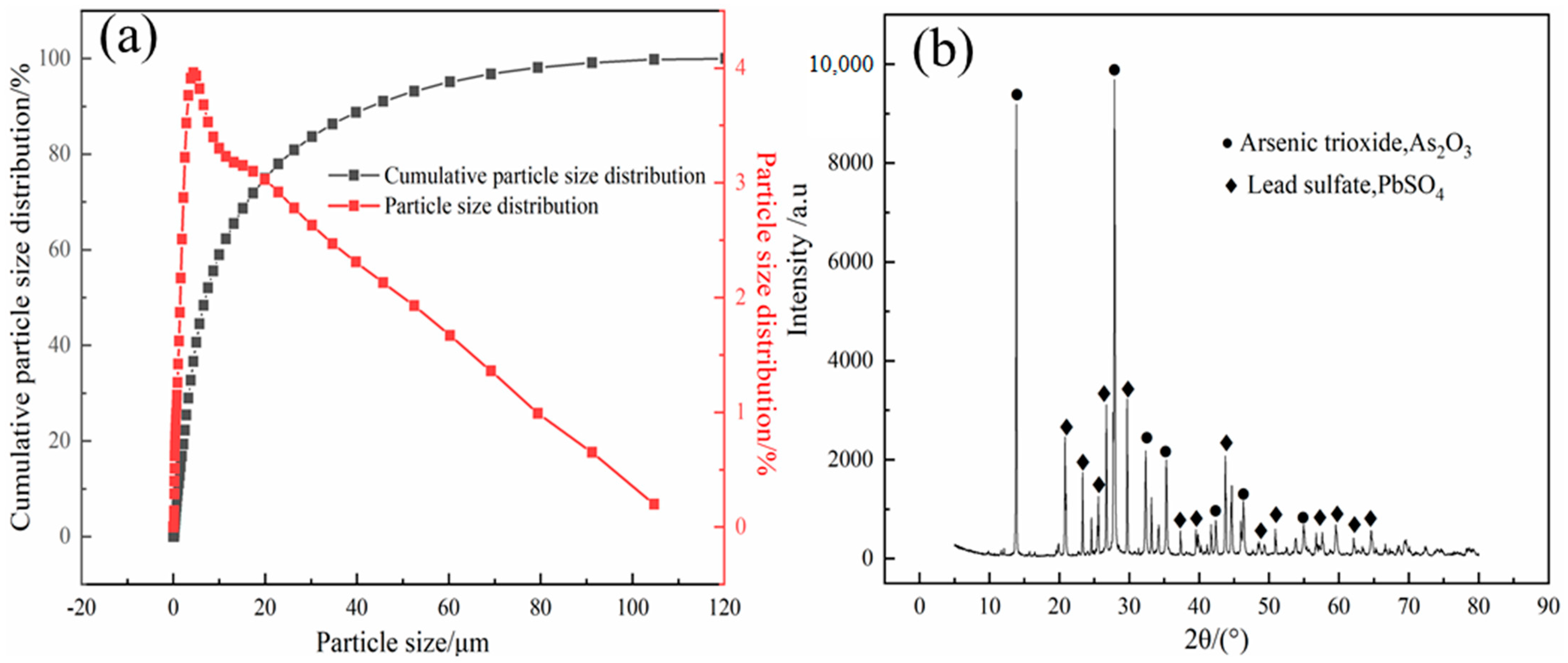
2.1. Materials
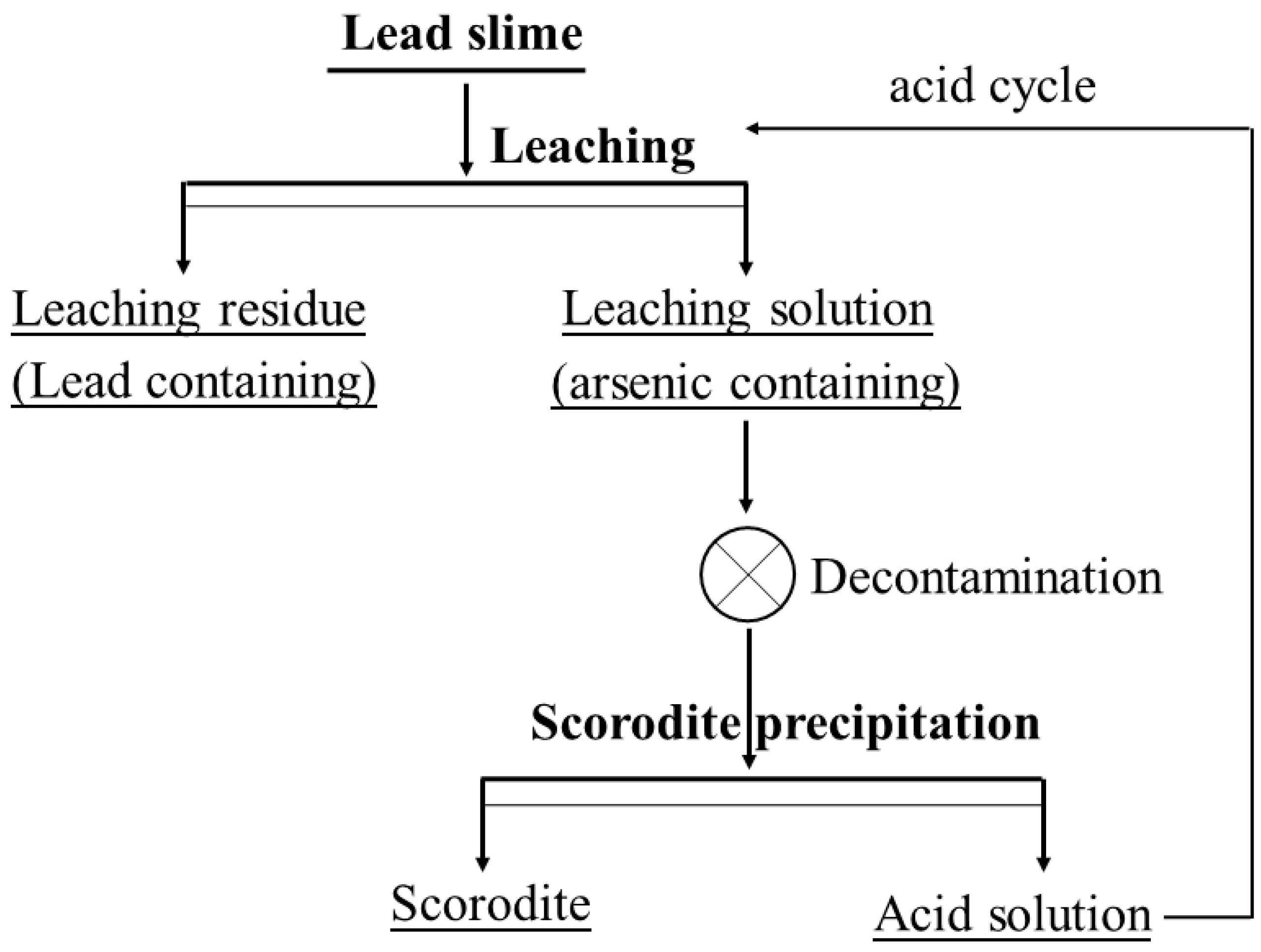
2.2. Experimental Procedure
3. Results and Discussion
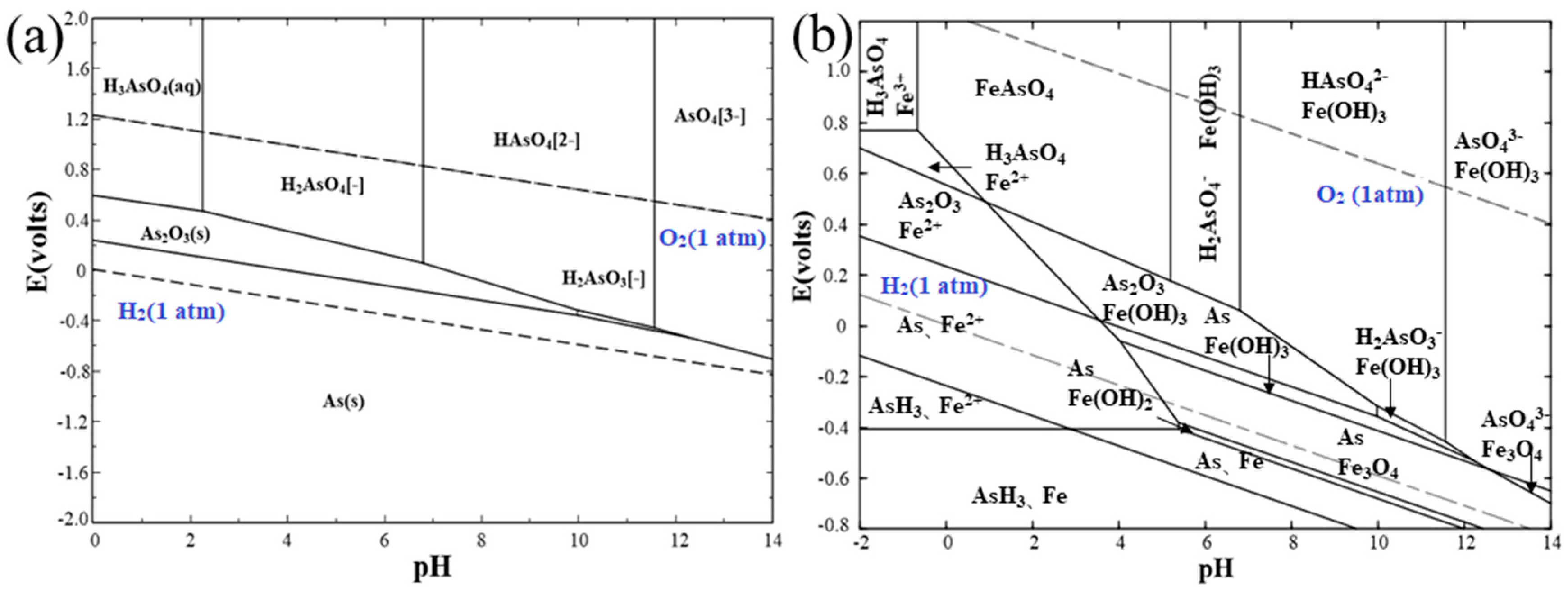
3.1. Thermodynamic Calculation
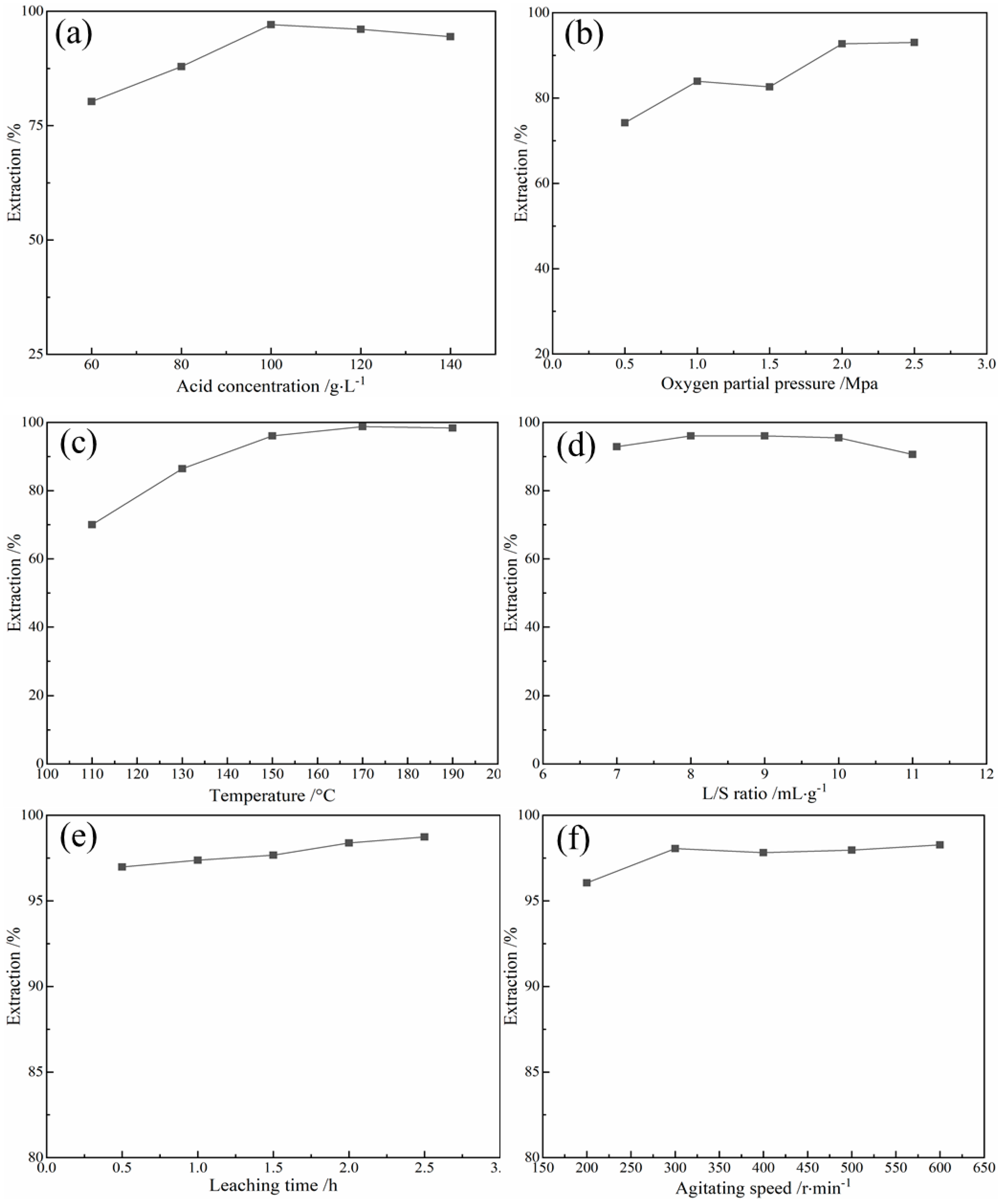
3.2. Acid Pressure Oxidation Leaching
3.3. Scorodite Precipitation
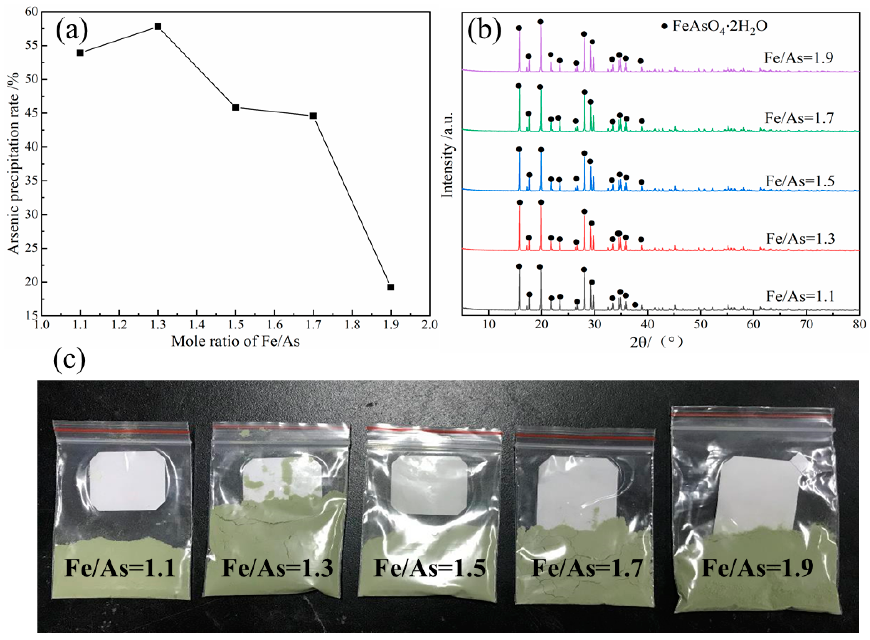
3.3.1. Effect of Initial Fe/As Ratio
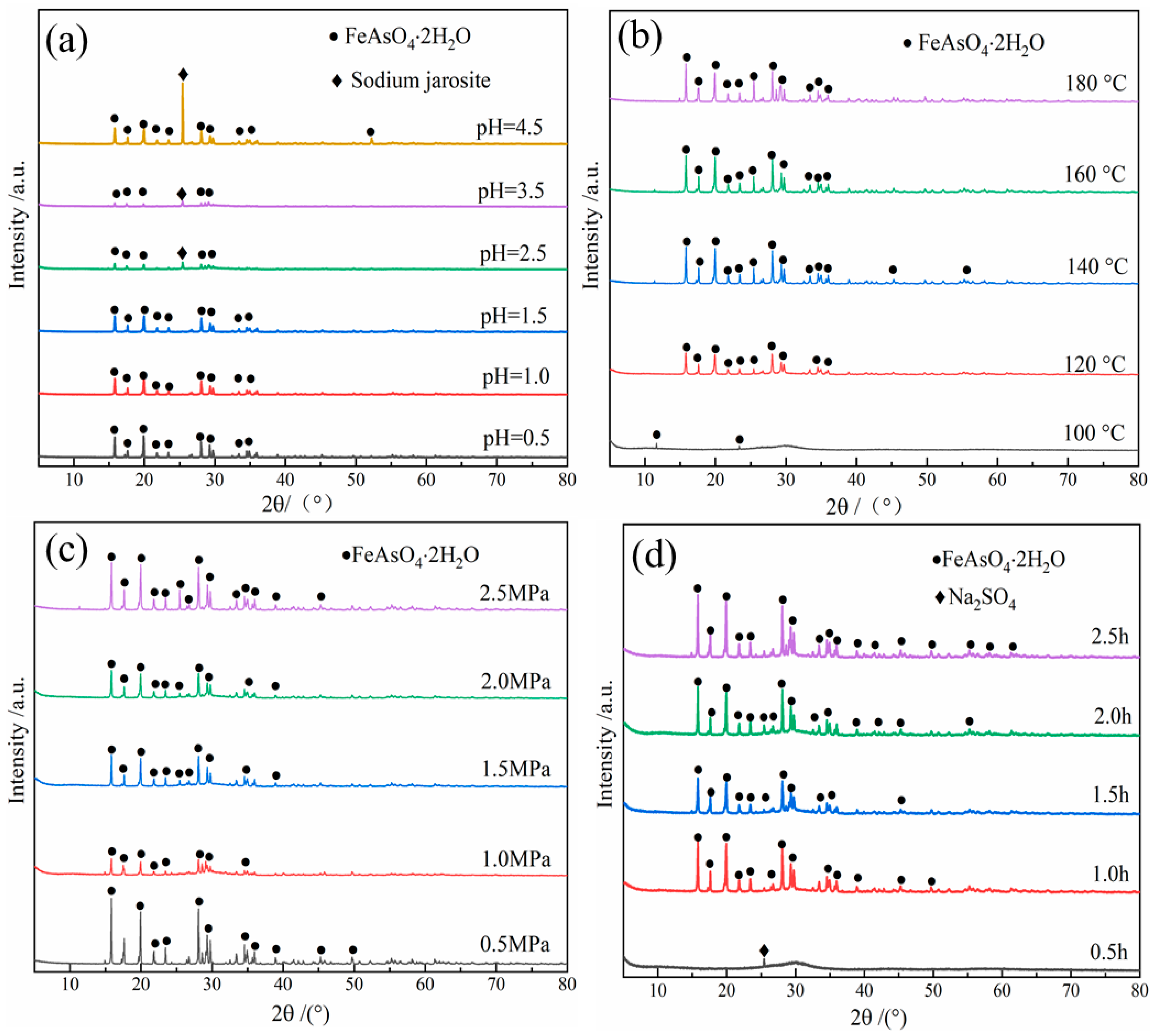
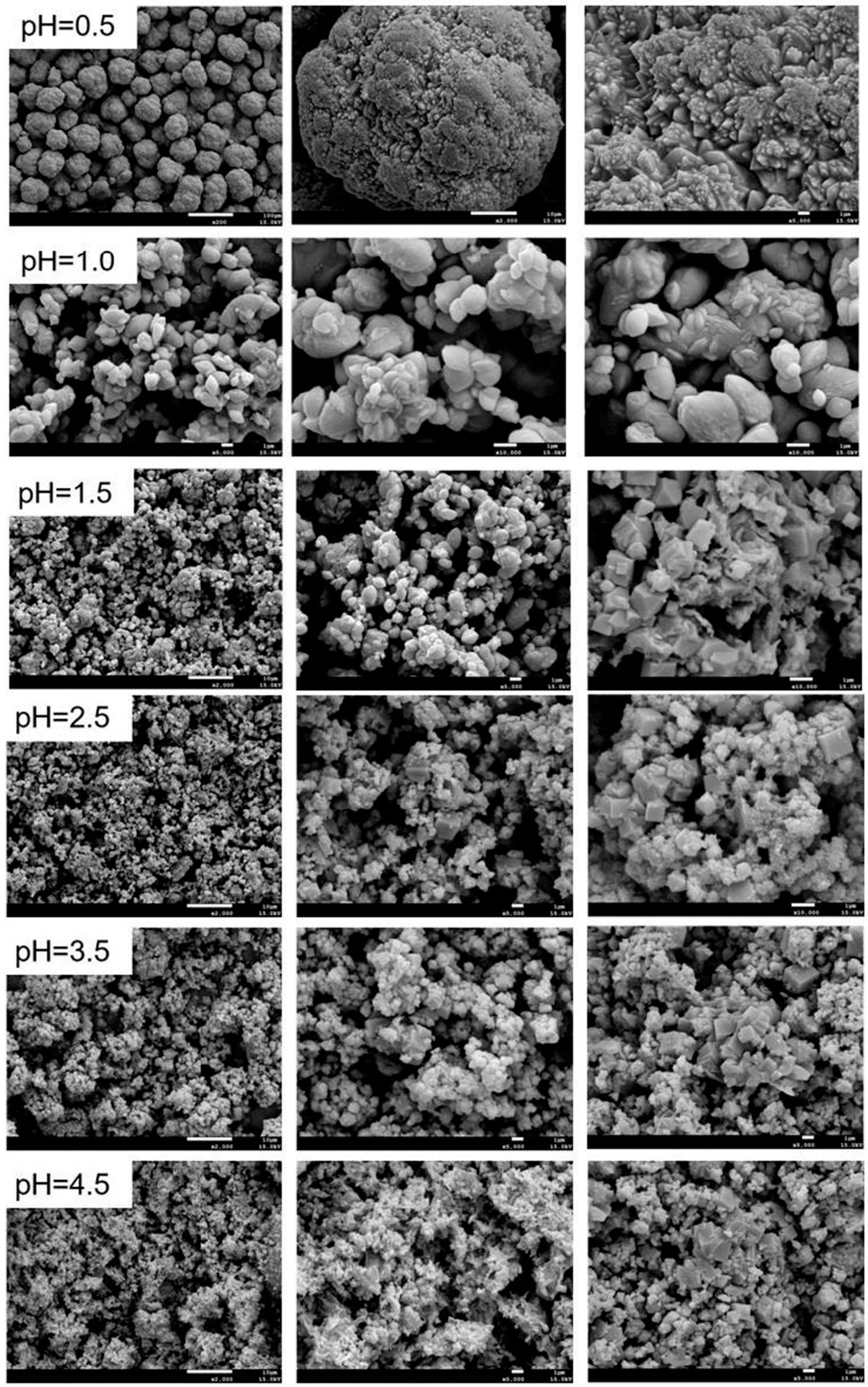
3.3.2. Effect of Initial pH Value
3.3.3. Effect of Temperature
3.3.4. Effect of Oxygen Partial Pressure
3.3.5. Effect of Precipitation Time
4. Conclusions
- (1)
- Under the optimum conditions, namely, leaching temperature of 170 °C, acid concentration of 100 g/L, L/S of 10 mL/g, leaching time of 2.5 h, pO2 of 2.0 MPa and agitating speed of 300 r/min, the leaching rate of arsenic from lead slime was more than 99.10% and the arsenic content of the leaching residue was about 0.80%.
- (2)
- The arsenic in the leaching solution (37.18 g/L) was stabilized in the form of scorodite (FeAsO4·2H2O), while the optimum conditions were established as: Fe/As ratio of 1.3, initial pH value of 1.0, pO2 of 2.5 MPa, temperature of 160 °C and precipitation time of 2.0 h.
- (3)
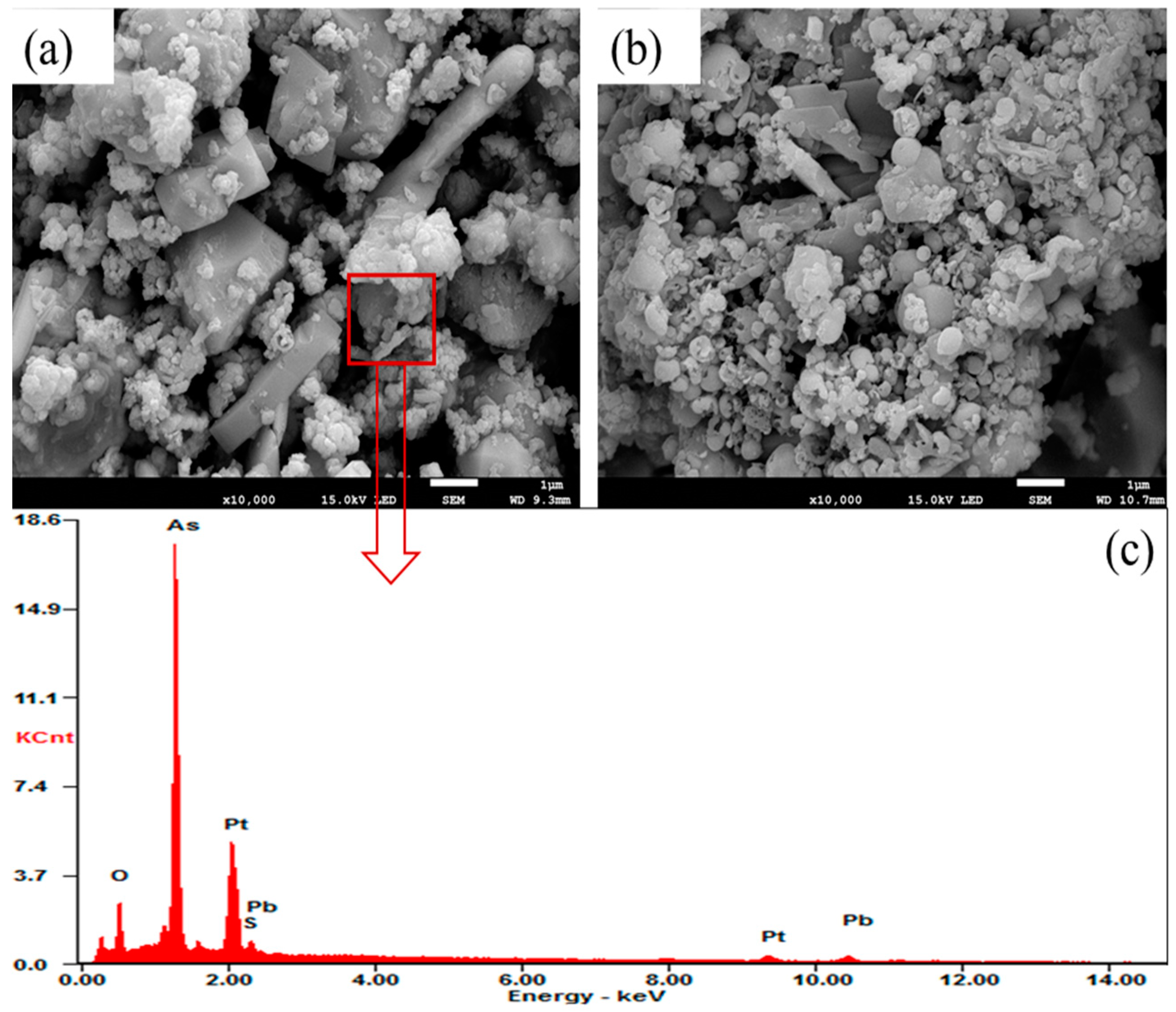
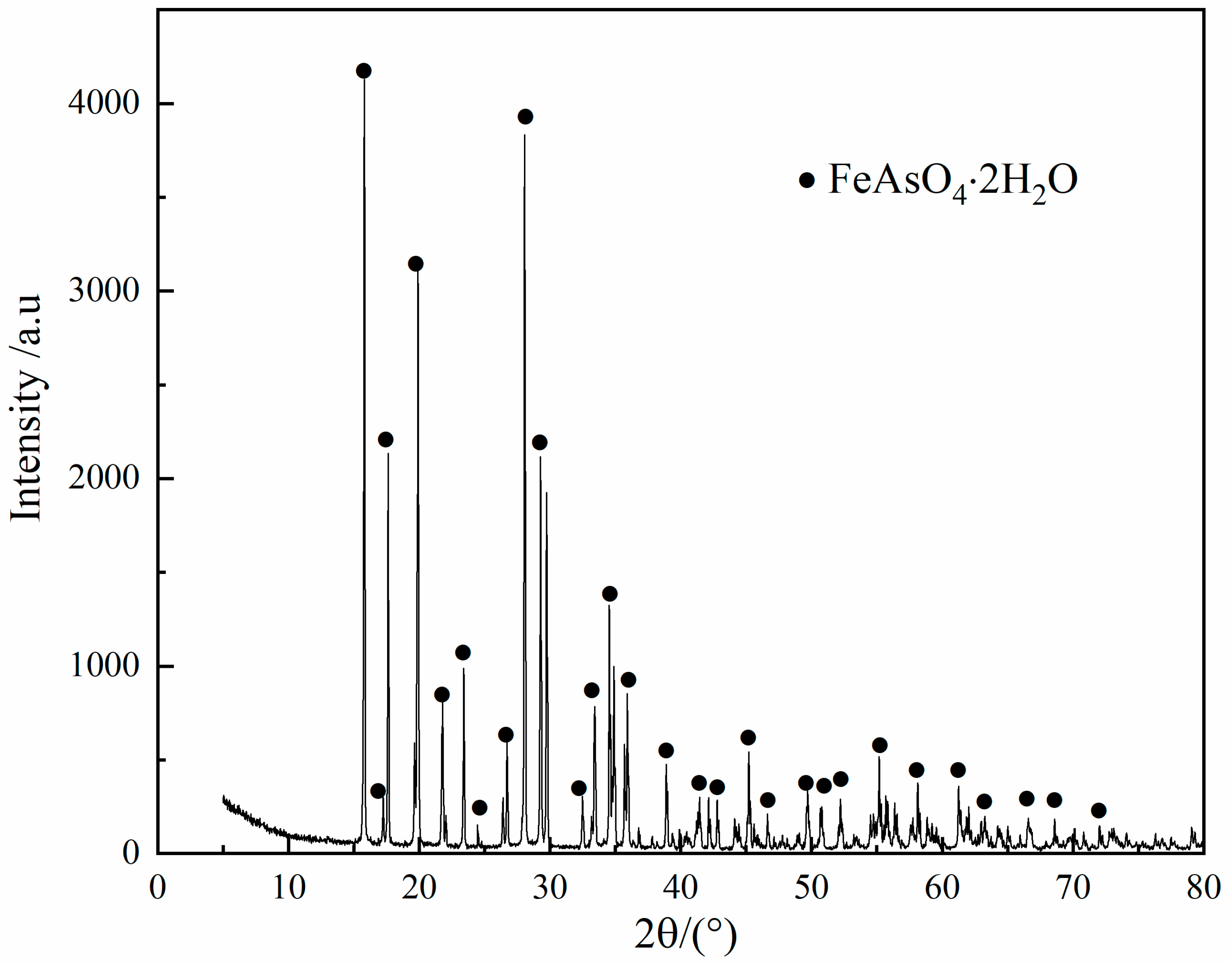
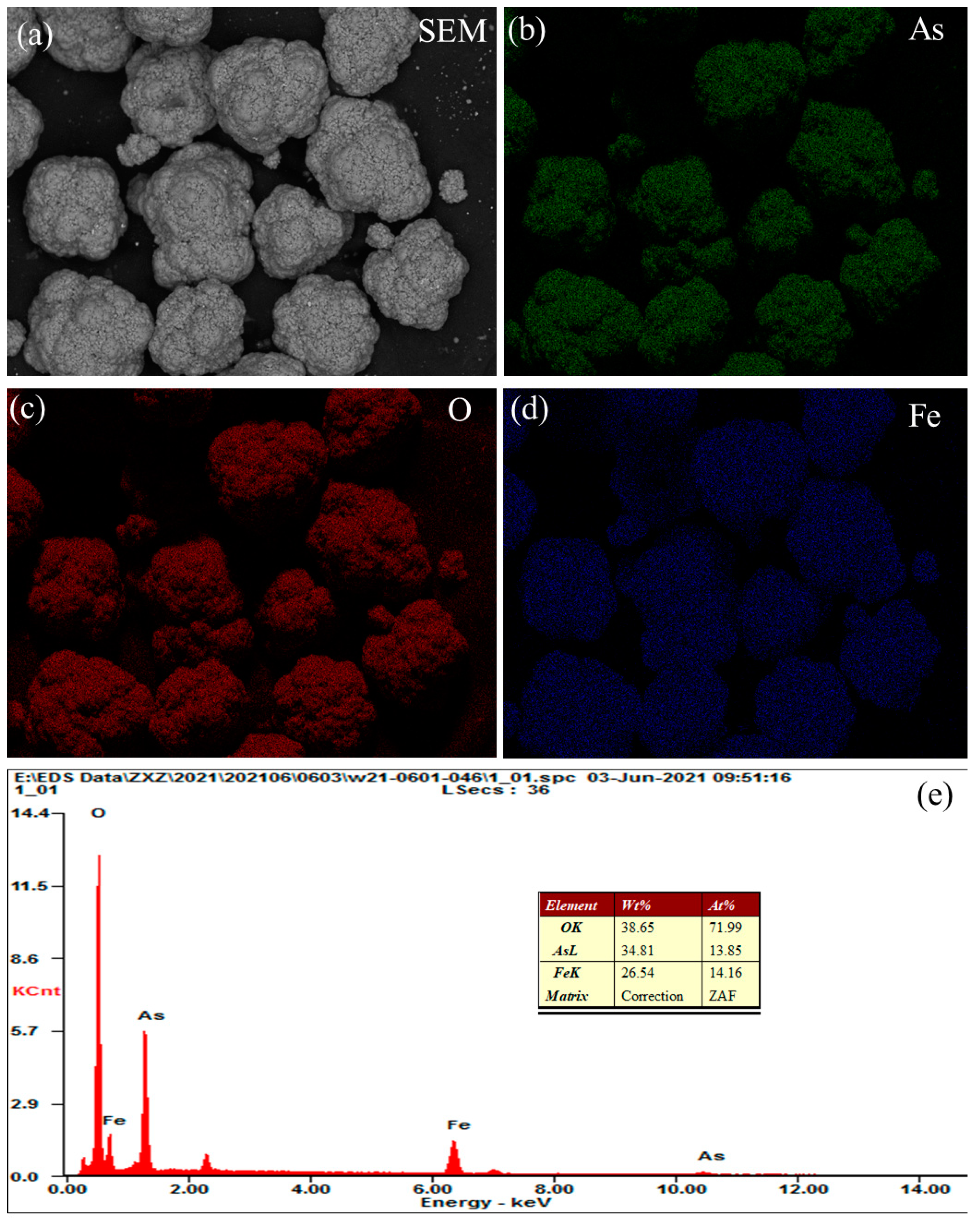
- Scorodite (FeAsO4·2H2O) with high purity was obtained by the proposed process, and the arsenic content in the resulting product reached as high as 98.50%.
Author Contributions
Funding
Acknowledgments
Conflicts of Interest
References
- Deonarine, A.; Kolker, A.; Doughten, M.W.; Holland, J.T.; Bailoo, J.D. Mobilization of arsenic from coal fly ash in the presence of dissolved organic matter. Appl. Geochem. 2021, 128, 11. [Google Scholar] [CrossRef]
- Liu, F.S.; Xu, Q.J.; Liang, H.Z.; Wang, H.Y.; Zhong, C.; Min, X.B.; Zhang, L.Y. Stabilization mechanism of arsenic-sulfide slag by density functional theory calculation of arsenic-sulfide clusters. J. Hazard. Mater. 2021, 410, 8. [Google Scholar] [CrossRef] [PubMed]
- Luo, Z.Q.; Mu, W.H.; Zhou, X.T.; Chen, Z. Removal and immobilization of arsenic from wastewater via arsenonatroalunite formation. Environ. Technol. 2021, 10, 1–10. [Google Scholar] [CrossRef] [PubMed]
- Zheng, G.Y.; Xia, J.P.; Liu, H.L.; Chen, Z.J. Arsenic removal from acid extraction solutions of copper smelting flue dust. J. Clean. Prod. 2021, 283, 12. [Google Scholar] [CrossRef]
- Liu, W.; Huang, C.; Han, J.W.; Qin, W.Q. Removal and reuse of arsenic from arsenic-bearing purified residue by alkaline pressure oxidative leaching and reduction of As (V). Hydrometallurgy 2021, 199, 9. [Google Scholar] [CrossRef]
- Zeng, T.; Deng, Z.G.; Zhang, F.; Fan, G.; Wei, C.; Li, X.B.; Li, M.T.; Liu, H.Y. Removal of arsenic from “Dirty acid” wastewater via Waelz slag and the recovery of valuable metals. Hydrometallurgy 2021, 200, 10. [Google Scholar] [CrossRef]
- Han, J.; Liu, W.; Xue, K.; Qin, W.; Jiao, F.; Zhu, L. Influence of NH4HF2 activation on leaching of low-grade complex copper ore in NH3-NH4Cl solution. Sep. Purif. Technol. 2017, 181, 29–36. [Google Scholar] [CrossRef]
- Han, J.; Liang, C.; Liu, W.; Qin, W.; Jiao, F.; Li, W. Pretreatment of tin anode slime using alkaline pressure oxidative leaching. Sep. Purif. Technol. 2017, 174, 389–395. [Google Scholar] [CrossRef]
- Li, J.-S.; Chen, L.; Zhan, B.; Wang, L.; Poon, C.S.; Tsang, D.C.W. Sustainable stabilization/solidification of arsenic-containing soil by blast slag and cement blends. Chemosphere 2021, 271, 129868. [Google Scholar] [CrossRef]
- Wang, Y.; Liu, X.; Yan, J.; Ye, S. Selective extraction of arsenic and antimony from gold-bearing sludge using two-stage alkaline leaching. Resour. Conserv. Recycl. 2021, 167, 105388. [Google Scholar] [CrossRef]
- Wang, Q.W.; Lin, Q.H.; Li, Q.Z.; Li, K.Z.; Wu, L.Y.; Li, S.M.; Liu, H. As(III) removal from wastewater and direct stabilization by in-situ formation of Zn-Fe layered double hydroxides. J. Hazard. Mater. 2021, 403, 11. [Google Scholar] [CrossRef] [PubMed]
- Alvarez-Ayuso, E.; Murciego, A. Stabilization methods for the treatment of weathered arsenopyrite mine wastes: Arsenic immobilization under selective leaching conditions. J. Clean. Prod. 2021, 283, 18. [Google Scholar] [CrossRef]
- Kang, J.; Chen, Z.; Zhu, X.; Zhou, S.; Zhou, L.; Wang, Z.; Wang, J.; Khater, G.A.; Yue, Y. Effect of replacement of Na2O by Fe2O3 on the crystallization behavior and acid resistance of MgO–Al2O3–SiO2 glass-ceramics. J. Non-Cryst. Solids 2019, 503–504, 1–6. [Google Scholar] [CrossRef]
- Ma, X.; Yuan, Z.; Zhang, G.; Zhang, J.; Wang, X.; Wang, S.; Jia, Y. Alternative Method for the Treatment of Hydrometallurgical Arsenic-Calcium Residues: The Immobilization of Arsenic as Scorodite. ACS Omega 2020, 5, 12979–12988. [Google Scholar] [CrossRef] [PubMed]
- Zhao, Z.; Song, Y.; Min, X.; Liang, Y.; Chai, L.; Shi, M. XPS and FTIR studies of sodium arsenate vitrification by cullet. J. Non-Cryst. Solids 2016, 452, 238–244. [Google Scholar] [CrossRef]
- Zhao, Z.W.; Chai, L.Y.; Peng, B.; Liang, Y.J.; He, Y.H.; Yan, Z.H. Arsenic vitrification by copper slag based glass: Mechanism and stability studies. J. Non-Cryst. Solids 2017, 466, 21–28. [Google Scholar] [CrossRef]
- Zhao, Z.; Wang, Z.; Xu, W.; Qin, W.; Lei, J.; Dong, Z.; Liang, Y. Arsenic removal from copper slag matrix by high temperature sulfide-reduction-volatilization. J. Hazard. Mater. 2021, 415, 125642. [Google Scholar] [CrossRef] [PubMed]
- Zhang, W.-L.; Zhao, L.-Y.; Yuan, Z.-J.; Li, D.-Q.; Morrison, L. Assessment of the long-term leaching characteristics of cement-slag stabilized/solidified contaminated sediment. Chemosphere 2021, 267, 128926. [Google Scholar] [CrossRef]
- Zhao, Z.; Chai, L.; Liang, Y.; Min, X.; Fei, J.; Ma, J. The vitrification of arsenic-rich residue using iron phosphate glass. Phys. Chem. Glasses B 2017, 58, 109–114. [Google Scholar] [CrossRef]
- Van, L.-N.; Sjoberg, V.; Ngoc Phuoc, D.; Duong Huu, H.; Karlsson, S. Removal mechanism of arsenic (V) by stainless steel slags obtained from scrap metal recycling. J. Environ. Chem. Eng. 2020, 8, 103833. [Google Scholar]
- Mirazimi, M.; Liu, W.Y. Aqueous arsenic and sulfur speciation analysis and solid phase characterization in the dissolution of arsenic trisulfide. Hydrometallurgy 2021, 199, 105545. [Google Scholar] [CrossRef]
- Boboev, I.R.; Tabarov, F.S. Removal of scorodite arsenic from gold ore in the form of As2S3 and As4S4. Hydrometallurgy 2021, 199, 105530. [Google Scholar] [CrossRef]
- Kalra, S.; Vyas, S.; Tiwari, M.; Ismail, Y.; Yupapin, P.; Ali, J.; Singh, G. Investigation of As2S3-borosilicate chalcogenide glass-based dispersion-engineered photonic crystal fibre for broadband supercontinuum generation in the mid-IR region. J. Mod. Opt. 2020, 67, 920–926. [Google Scholar] [CrossRef]
- Caplan, M.; Trouba, J.; Anderson, C.; Wang, S.J. Hydrometallurgical Leaching of Copper Flash Furnace Electrostatic Precipitator Dust for the Separation of Copper from Bismuth and Arsenic. Metals 2021, 11, 371. [Google Scholar] [CrossRef]
- Gu, K.; Li, W.; Han, J.; Liu, W.; Qin, W.; Cai, L. Arsenic removal from lead-zinc smelter ash by NaOH-H2O2 leaching. Sep. Purif. Technol. 2019, 209, 128–135. [Google Scholar] [CrossRef]
- Pozo, G.; van Houtven, D.; Fransaer, J.; Dominguez-Benetton, X. Arsenic immobilization as crystalline scorodite by gas-diffusion electrocrystallization. React. Chem. Eng. 2020, 5, 1118–1128. [Google Scholar] [CrossRef]
- Zhang, H.; Wang, Y.; He, Y.; Xu, S.; Hu, B.; Cao, H.; Zhou, J.; Zheng, G. Efficient and safe disposition of arsenic by incorporation in smelting slag through copper flash smelting process. Miner. Eng. 2021, 160, 105562. [Google Scholar] [CrossRef]
- Fei, J.; Ma, J.; Yang, J.; Liang, Y.; Ke, Y.; Yao, L.; Li, Y.; Liu, D.; Min, X. Effect of simulated acid rain on stability of arsenic calcium residue in residue field. Environ. Geochem. Health 2020, 42, 769–780. [Google Scholar] [CrossRef] [PubMed]
- Tian, L.; Huang, L.Q.; Xu, J.C.; Yu, X.Q.; Xu, Z.F. Study on the solvent extraction of thioarsenite in alkaline solutions with transformed quaternary ammonium salt. Hydrometallurgy 2021, 199, 12. [Google Scholar] [CrossRef]
- Du, M.; Liu, H.; Hu, D.; Huang, J.; Liu, Z.; Fang, Y. The leaching mechanism of heavy metals (Ni, Cd, As) in a gasification slag during acidification. Waste Manag. 2020, 114, 17–24. [Google Scholar] [CrossRef] [PubMed]
- Guo, L.; Hu, Z.; Du, Y.; Zhang, T.C.; Du, D. Mechanochemical activation on selective leaching of arsenic from copper smelting flue dusts. J. Hazard. Mater. 2021, 414, 125436–125446. [Google Scholar] [CrossRef] [PubMed]
- Shi, M.-Q.; Min, X.-B.; Shen, C.; Chai, L.-Y.; Ke, Y.; Yan, X.; Liang, Y.-J. Separation and recovery of copper in Cu-As-bearing copper electrorefining black slime by oxidation acid leaching and sulfide precipitation. Trans. Nonferrous Met. Soc. China 2021, 31, 1103–1112. [Google Scholar] [CrossRef]
- Han, J.; Liu, W.; Wang, D.; Jiao, F.; Qin, W. Selective Sulfidation of Lead Smelter Slag with Sulfur. Metall. Mater. Trans. B-Proc. Metall. Mater. Proc. Sci. 2016, 47, 344–354. [Google Scholar] [CrossRef]
- Jiao, F.; Li, W.; Xue, K.; Yang, C.; Qin, W. Recovery of chromium and magnesium from spent magnesia-chrome refractories by acid leaching combined with alkali precipitation and evaporation. Sep. Purif. Technol. 2019, 227, 115705. [Google Scholar] [CrossRef]
- Zhang, W.; Lu, H.; Liu, F.; Wang, C.; Zhang, Z.; Zhang, J. Hydrothermal treatment of arsenic sulfide slag to immobilize arsenic into scorodite and recycle sulfur. J. Hazard. Mater. 2021, 406, 124735. [Google Scholar] [CrossRef]
- Li, X.; Cai, G.; Li, Y.; Zhu, X.; Qi, X.; Zhang, X.; Shu, B.; Li, K.; Wei, Y.; Wang, H. Limonite as a source of solid iron in the crystallization of scorodite aiming at arsenic removal from smelting wastewater. J. Clean. Prod. 2021, 278, 123552. [Google Scholar] [CrossRef]
- Li, Y.; Zhu, X.; Qi, X.; Shu, B.; Zhang, X.; Li, K.; Wei, Y.; Hao, F.; Wang, H. Efficient removal of arsenic from copper smelting wastewater in form of scorodite using copper slag. J. Clean. Prod. 2020, 270, 122428. [Google Scholar] [CrossRef]
- Nazari, A.M.; Radzinski, R.; Ghahreman, A. Review of arsenic metallurgy: Treatment of arsenical minerals and the immobilization of arsenic. Hydrometallurgy 2017, 174, 258–281. [Google Scholar] [CrossRef]
- Sun, Y.; Yao, Q.; Zhang, X.; Yang, H.; Li, N.; Zhang, Z.; Hao, Z. Insight into mineralizer modified and tailored scorodite crystal characteristics and leachability for arsenic-rich smelter wastewater stabilization. RSC Adv. 2018, 8, 19560–19569. [Google Scholar] [CrossRef] [Green Version]
- Fujita, T.; Taguchi, R.; Abumiya, M.; Matsumoto, M.; Shibata, E.; Nakamura, T. Effect of pH on atmospheric scorodite synthesis by oxidation of ferrous ions: Physical properties and stability of the scorodite. Hydrometallurgy 2009, 96, 189–198. [Google Scholar] [CrossRef]
- Fujita, T.; Fujieda, S.; Shinoda, K.; Suzuki, S. Environmental leaching characteristics of scorodite synthesized with Fe(II) ions. Hydrometallurgy 2012, 111, 87–102. [Google Scholar] [CrossRef]
- Li, W.; Han, J.; Liu, W.; Jiao, F.; Wang, H.; Qin, W. Separation of arsenic from lead smelter ash by acid leaching combined with pressure oxidation. Sep. Purif. Technol. 2021, 273, 118988. [Google Scholar] [CrossRef]
- Min, X.-B.; Liao, Y.-P.; Chai, L.-Y.; Yang, Z.-H.; Xiong, S.; Liu, L.; Li, Q.-Z. Removal and stabilization of arsenic from anode slime by forming crystal scorodite. Trans. Nonferrous Met. Soc. China 2015, 25, 1298–1306. [Google Scholar] [CrossRef]
- Alka, S.; Shahir, S.; Ibrahim, N.; Ndejiko, M.J.; Vo, D.-V.N.; Manan, F.A. Arsenic removal technologies and future trends: A mini review. J. Clean. Prod. 2021, 278, 123805. [Google Scholar] [CrossRef]
- Liu, W.; Li, W.; Han, J.; Wu, D.; Li, Z.; Gu, K.; Qin, W. Preparation of calcium stannate from lead refining slag by alkaline leaching-purification-causticization process. Sep. Purif. Technol. 2019, 212, 119–125. [Google Scholar] [CrossRef]
- Gomez, M.A.; Becze, L.; Cutler, J.N.; Demopoulos, G.P. Hydrothermal reaction chemistry and characterization of ferric arsenate phases precipitated from Fe2(SO4)3-As2O5-H2SO4 solutions. Hydrometallurgy 2011, 107, 74–90. [Google Scholar] [CrossRef]
- Mambote, R.C.M.; Krijgsman, P.; Reuter, M.A. Hydrothermal precipitation of arsenic compounds in the ferric-arsenic (III)-sulfate system: Thermodynamic modeling. Miner. Eng. 2003, 16, 429–440. [Google Scholar] [CrossRef]
- Chen, Y.; Liu, N.; Ye, L.; Xiong, S.; Yang, S. A cleaning process for the removal and stabilisation of arsenic from arsenic-rich lead anode slime. J. Clean. Prod. 2018, 176, 26–35. [Google Scholar] [CrossRef]
- Verma, P. Arsenic removal from water through adsorption—A Review. Recent Res. Sci. Technol. 2014, 6, 219–226. [Google Scholar]
- Song, K.Z.; Ke, P.C.; Liu, Z.Y.; Liu, Z.H. Co-oxidation of arsenic(III) and iron(II) ions by pressurized oxygen in acidic solutions. Int. J. Miner. Metall. Mater. 2020, 27, 181–189. [Google Scholar] [CrossRef]
- Debekaussen, R.; Droppert, D.; Demopoulos, G.P. Ambient pressure hydrometallurgical conversion of arsenic trioxide to crystalline scorodite. Cim. Bull. 2001, 94, 116–122. [Google Scholar]
- Paktunc, D.; Dutrizac, J.; Gertsman, V. Synthesis and phase transformations involving scorodite, ferric arsenate and arsenical ferrihydrite: Implications for arsenic mobility. Geochim. Cosmochim. Acta 2008, 72, 2649–2672. [Google Scholar] [CrossRef]


| Elements | Pb | Cd | Sb | In | Zn | As | Sn |
|---|---|---|---|---|---|---|---|
| Content | 15.10 | 1.44 | 0.04 | 0.04 | 0.25 | 33.47 | 2.50 |
| No. | Solution | Residue | Leaching Rate /% | ||
|---|---|---|---|---|---|
| Volume /mL | As Concentrationg /L | Mass /g | As Content /% | ||
| I | 550 | 36.17 | 24.43 | 0.77 | 99.06 |
| II | 540 | 36.88 | 23.52 | 0.71 | 99.17 |
| No. | Precipitation Rate/% | Residue Content/% | |
|---|---|---|---|
| As | Fe | ||
| I | 99.12 | 30.12 | 22.81 |
| II | 97.88 | 30.89 | 21.76 |
| Mean | 98.50 | 30.51 | 22.29 |
Publisher’s Note: MDPI stays neutral with regard to jurisdictional claims in published maps and institutional affiliations. |
© 2021 by the authors. Licensee MDPI, Basel, Switzerland. This article is an open access article distributed under the terms and conditions of the Creative Commons Attribution (CC BY) license (https://creativecommons.org/licenses/by/4.0/).
Share and Cite
Li, W.; Liu, W.; Liu, H.; Wang, H.; Qin, W. Separation and Stabilization of Arsenic from Lead Slime by the Combination of Acid Leaching and Forming Scorodite. Minerals 2021, 11, 1319. https://doi.org/10.3390/min11121319
Li W, Liu W, Liu H, Wang H, Qin W. Separation and Stabilization of Arsenic from Lead Slime by the Combination of Acid Leaching and Forming Scorodite. Minerals. 2021; 11(12):1319. https://doi.org/10.3390/min11121319
Chicago/Turabian StyleLi, Wenhua, Wei Liu, Hongwei Liu, Huanlong Wang, and Wenqing Qin. 2021. "Separation and Stabilization of Arsenic from Lead Slime by the Combination of Acid Leaching and Forming Scorodite" Minerals 11, no. 12: 1319. https://doi.org/10.3390/min11121319
APA StyleLi, W., Liu, W., Liu, H., Wang, H., & Qin, W. (2021). Separation and Stabilization of Arsenic from Lead Slime by the Combination of Acid Leaching and Forming Scorodite. Minerals, 11(12), 1319. https://doi.org/10.3390/min11121319