Article

Optimization of Airflow Field for Pneumatic Drum Magnetic Separator to Improve the Separation Efficiency

School of Minerals Processing and Bioengineering, Central South University, Changsha 410083, China
*
Authors to whom correspondence should be addressed.
Minerals 2021, 11(11), 1228; https://doi.org/10.3390/min11111228
Submission received: 13 August 2021 / Revised: 1 November 2021 / Accepted: 2 November 2021 / Published: 5 November 2021
(This article belongs to the Topic Advances in Separation and Purification Techniques)

Abstract

:
Traditional dry magnetic separation has poor separation efficiency for fine-grained materials, and combining airflow and a magnetic field may be one of the most effective means to improve it. Based on the pneumatic drum magnetic separator developed by our team, an improved pneumatic magnetic separator with a segmented flow field is proposed, which pushes materials to move along the separation surface. Analysis of flow field in the separation zone and the forces on particles show that the improved pneumatic magnetic separator makes it easier to collect fine magnetic particles, while nonmagnetic particles are more easily removed by airflow. Separation test results also show that the iron grade and the recovery of concentrate improved from 37.89% and 74.75% to 51.76% and 91.79%, respectively. The separation efficiency of the pneumatic drum magnetic separator has been remarkably improved by optimizing airflow field in the separation zone.

1. Introduction

Magnetic separation is a technology to separate magnetic components from nonmagnetic materials in a nonuniform magnetic field, based on their magnetic differences [1,2]. In recent years, due to the rising costs associated with environmental protection and the increasing demand for iron in polar regions (extremely cold and hot regions), dry magnetic separation highlights its greater application advantages [3]; however, for fine-grained iron ores, the separation efficiency of dry magnetic separation is lower than that of wet magnetic separation. This is mainly because the mechanical inclusion caused by magnetic agglomeration and the nonspecific adhesion between fine particles in dry magnetic separation are more severe than that in wet magnetic separation [4,5,6].
Although there are many factors affecting nonspecific adhesion between particles, few effective measures can be taken to improve particle dispersion in magnetic separation and mechanical dispersion is the easiest and an effective compulsory dispersion method. To improve the efficiency of dry magnetic separation for fine-grained materials, it is usually necessary to introduce other mechanical forces to destroy particle clusters formed by magnetic and nonmagnetic particles (or by rich and poor coenobium) [5,7,8,9,10,11]. Mechanical force is caused by the impact of high-speed moving machinery, or the strong turbulence of airflow generated by jet entrainment and the direct impact of high-speed airflow. The needed condition of mechanical dispersion is that mechanical force (usually refers to the shear force and pressure difference force of fluid) should be greater than the adhesion force between particles [1]. Additionally, introduction of mechanical force is essential for strengthening the turbulence intensity of flow field in separation zone. However, the separation efficiency of industrial dry magnetic separation has been improved, mostly by removing ultrafine particles in advance [12,13], which is similar to the separation of fine weak magnetic materials in wet magnetic separation, where the ultrafine magnetic particles will be lost with water [14].
It is worth noting that combing high-speed airflow and traditional dry magnetic separation is an effective way to improve efficiency in dry magnetic separation. In recent years, new dry magnetic separation equipment has emerged. The effects of airflow can be summarized into three categories: (1) removing fine materials [15]; (2) promoting fluidization of materials [16,17,18,19,20,21,22]; and (3) impacting materials to remove inclusions [23].
A new pneumatic magnetic separator [24], recently proposed by our research group, can efficiently lessen inclusions by fluidizing materials, realizing the efficient separation of strong magnetic materials. However, the undifferentiated airflow field in the original equipment will result in a lower concentrate recovery. Based on the original drum pneumatic magnetic separator, this paper puts forward a segmented airflow field type pneumatic magnetic separator. The advanced nature of the equipment is illustrated by airflow field simulations and particle force analyses. Experimental tests on artificial mixtures of magnetite and quartz revealed a good separation performance for the new separator. The main significance of this paper is to explain the key role of airflow field regulation in the separation zone for improving separation efficiency of a pneumatic drum magnetic separator.

2. Experimental Section

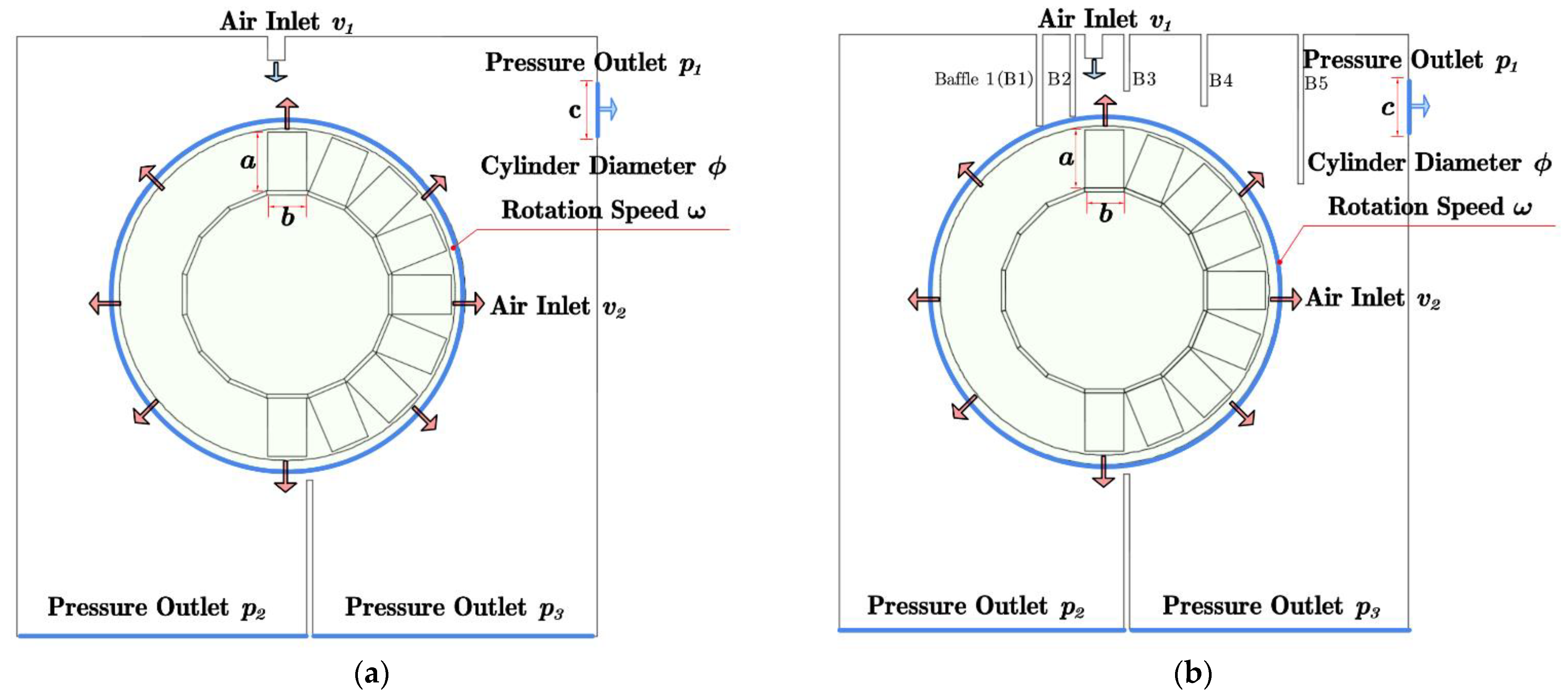
2.1. Configuration Improvement of Pneumatic Drum Magnetic Separator

The basic configurations of the original and improved pneumatic drum magnetic separators are, respectively, shown in Figure 1a,b [24]. Concentrate with a high grade and low recovery is usually obtained using the original equipment. The reason for this lies in the openness of the external airflow field of the equipment. Many fine magnetic materials are blown away from the separation surface by the airflow and enter the tailings side. To solve this problem, several baffles were set in the separation zone of the new separator. On the one hand, the airflow field is blocked and the material must pass through a certain distance the drum surface alone, avoiding that the magnetic material is blown into the tailings side without separation. On the other hand, the airflow field distribution is optimized and the movement direction of particles is regulated.

2.2. Materials

Magnetite was purified by weak magnetic separation from a high-grade magnetic concentration, sampled from the mine of Daye in Hubei Province, China. Bulk quartz was supplied by Xinjiang Koktokay Rare Metal Mine, China. The quartz was crushed with a hammer and handpicked to remove impure minerals and then ground in a porcelain mill with agate balls. The magnetite and quartz samples were then sieved individually to get the size fraction of −0.038 + 0.023 mm. The assayed total iron grade of magnetite was 71.04% and the assayed SiO2 content of quartz was 99.60%. Artificial mixtures of 5 g magnetite and 15 g quartz were used as feed on account of the capacity of the separator for each test.

2.3. Experimental and Evaluation Methods

Magnetic field intensity of the drum surface was set at about 900Gs (measured using a Gauss meter). The airflow velocity and drum rotation speed were adjusted to specified values (0–0.64 m/s). Then, the artificial mixture was fed at a constant speed from the material inlet. When the mixture enters the separation zone, it was first fluidized. With the action of a large magnetic force and a low air drag force, magnetite particles will stay on the separation surface and move forward with the drum, and then finally they are dropped into the concentrate hopper. In contrast, the quartz particles move away from the separation plane because of the large air drag force and enter the tailing hopper. The concentrate and tailings are weighed and assayed for iron grade to calculate the iron recovery.
Iron grade and recovery of the concentrate and separation efficiency were adopted to evaluate the separation performance under different test conditions. Based on the assayed iron grade, the iron recovery of the concentrate (ε) and separation efficiency of the test (E) were calculated using the following formulas:
ε = β ( α θ ) α ( β θ ) × 100 %
E = ε ( β α ) ( β max α ) × 100 %
Here, α, β, and θ represent the iron grade of the feed, concentrate, and tailings; βmax is the theoretical iron grade of magnetite (71.04%).

2.4. Simulation Method and Conditions

A two-dimensional model built by COMSOL 5.3a (COMSOL. Inc., Burlington, MA, USA) was adopted to simulate the airflow field of the magnetic separator. Geometric models of the original and improved pneumatic drum magnetic separators are shown in Figure 2. The magnetic field was solved based on the scalar magnetic potential Laplace equation. The transient Reynolds averaged NS equation (RANS) was used to solve the airflow field using a realizable model as the turbulence model. A free triangle grid in Cartesian coordinates was used after the optimization of the boundary layer grid. The number of grids of the original and improved platforms are 68,160 and 77,621, respectively, and the maximum and minimum grid size are 3 mm and 0.005 mm. A stable turbulent airflow field was selected as representative of the results. Specific parameters used in the simulation are shown in Table 1.
Based on the calculated physical field data, the different forces on particles can be obtained as follows:
Gravity of magnetite and quartz can be given by:
G m = ρ m g π d 3 6
G q = ρ q g π d 3 6
where g is gravitational acceleration, d is diameter of particle, ρ m and ρ q are density of magnetite and quartz.
The magnetic force on magnetite can be given by [25]:
F m = ρ m μ 0 χ π d 3 6 H H
where μ 0 is the permeability of vacuum, χ is the susceptibility of magnetite, and H is the external magnetic field intensity.
Air drag force F D on particles can be given by the Schiller–Naumann model [26,27].
F D = 1 𝝉 p m p ( u f u p )
τ p = 4 ρ p d 2 3 μ C D R e
C D = 24 R e ( 1 + 0.15 R e 0.687 )
R e = ρ | u f u p | d μ
where m p is the mass of the particle, τ p is the particle velocity response time, u f and u p are, respectively, velocity of airflow and particle, μ is the viscosity coefficient of air, C D is the resistance coefficient, and R e is the Reynolds number of particles.

3. Results and Discussions

3.1. Airflow Field Simulation and Analysis

The equipment has different airflow field distributions under different drum rotation speeds or radial airflow incident velocities, and the airflow field of the improved one is the same as that of the original one near the separation surface (5–10 mm). However, at a certain distance (>10 mm) from the separation surface, the airflow fields are different. In this paper, only the airflow conditions of ω = 120 rpm and v2 = 0.64 m/s were taken as the representative airflow field distribution of the two magnetic separators, and is shown in Figure 3.
It can be seen from Figure 3 that the airflow field of the original pneumatic magnetic separator is simple. After entering the separation zone from the air inlet, the material will collide with the radial airflow on the separation surface (i.e., the drum surface), resulting in strong turbulence of airflow and the fluidization of materials. However, some fine magnetic particles will not be effectively attracted by the magnetic system and will enter the tailings side directly due to the airflow or the dust collector, as there is no baffle. Meanwhile, some nonmagnetic particles may directly enter the concentrate from the left side. This will reduce the recovery and separation accuracy of magnetic materials. The baffles can prevent particles from entering the concentrate from the left side, as shown by B1 and B2 in Figure 2. The material inlet airflow and the radial airflow on the drum surface collide and is mixed between baffles B2 and B3, which further enhances the shearing effect of the airflow on the loose particles. Fine materials are pushed to pass through the effective action range of the magnetic system by baffle B3, which greatly improves the recovery of fine magnetic materials. Baffles B4 and B5 can further hinder magnetic particles carried in the airflow and prevent them from directly entering the tailings side or the dust collector.

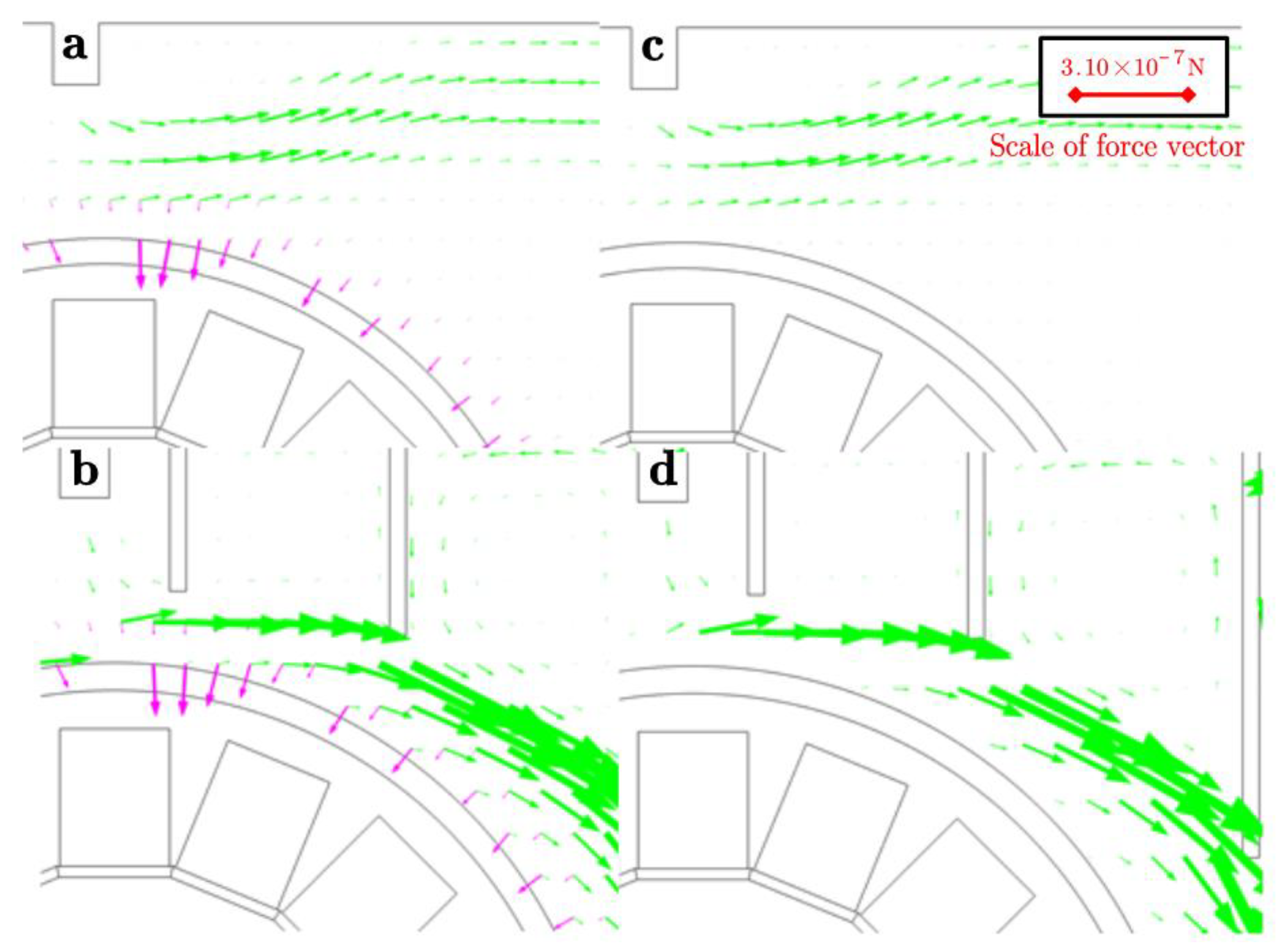
3.2. Particle Force Analysis in Separation Zone

The magnetic force, fluid drag force, and gravity acting on magnetite and quartz particles with a size of 23 μm, at different positions in the separation zone, were calculated and analyzed, as shown in Figure 4.
For 23 μm particles, compared with the magnetic force and the fluid drag force in the separation zone, the gravity of particles in Figure 4 is too small to show. For the original pneumatic magnetic separator (see Figure 4a,c), the airflow drag force on particles is rather small. The reason is that no baffle prevents particles from moving away from the separation surface with the airflow. The farther the particles are away from the separation surface, the smaller the magnetic force and drag force acting on the particles. For the improved pneumatic magnetic separator (see Figure 4b,d), particles were pushed to pass through the area near the separation surface by baffles, so the magnetic and airflow drag forces on particles are much larger than those of the original one. As a result, fine magnetic particles are easily collected by the magnetic system. At the same time, the high turbulence of the airflow, not only promotes immediate discharge of quartz from the separation system, but also provides a stronger shear effect to lessen particle magnetic agglomeration.

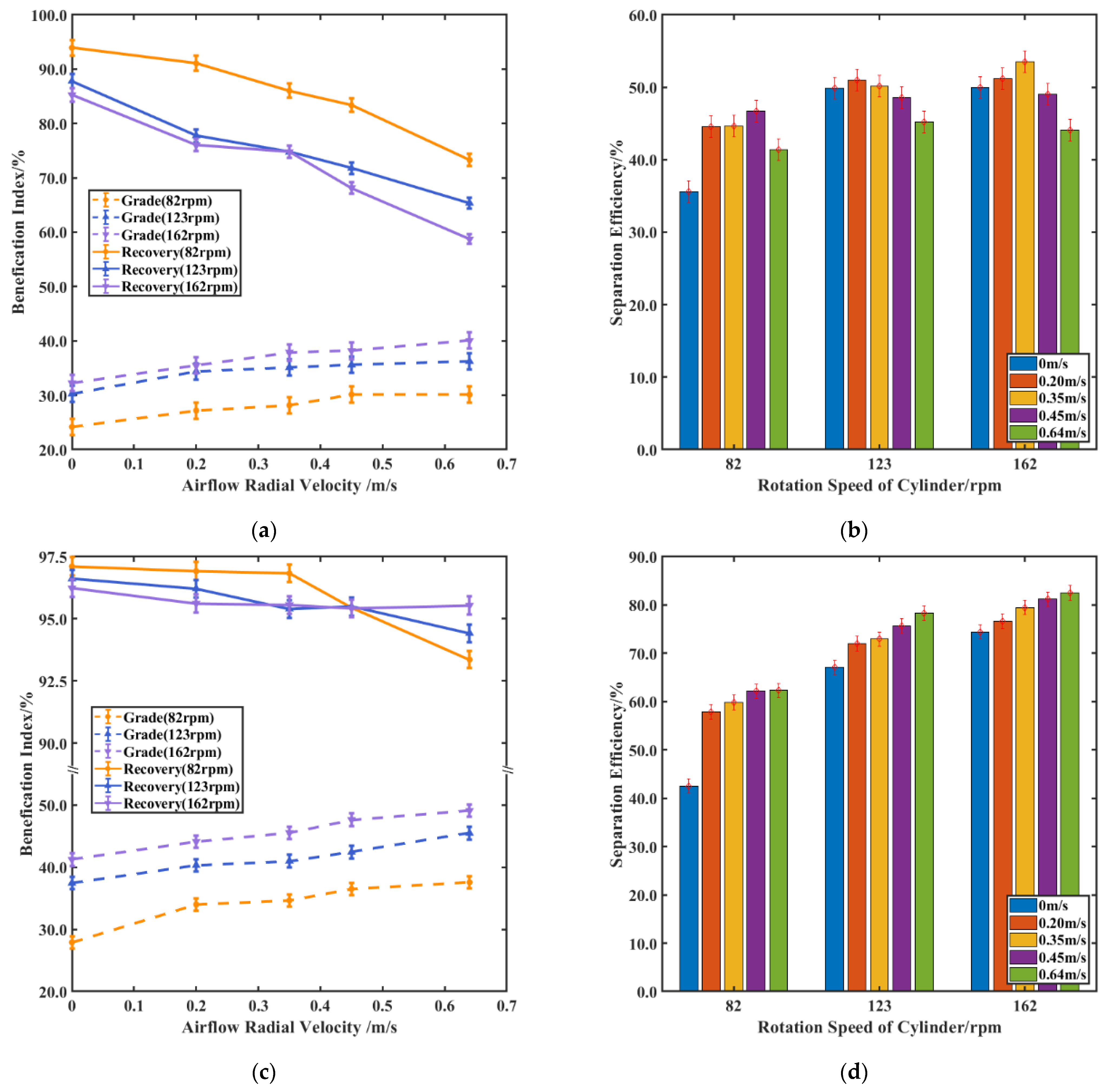
3.3. Experimental Verification

A series of separation tests were carried out with artificial mixtures of magnetite and quartz in the size fraction of −0.038 + 0.023 mm using the original and improved pneumatic magnetic separators. Under a magnetic field intensity of 900 Gs, the test results obtained at different rotation speeds and airflow velocities are shown in Figure 5.
It can be seen from Figure 5a,b that, with the increase in airflow velocity, the iron grade of the concentrate increased continuously while the iron recovery decreased more. Similarly, with the increase in the rotational speed of the drum, the iron grade of the concentrate increased and the iron recovery decreased gradually. This indicates that the drag effect of radial air flow on particles and the centrifugal effect of the drum rotation on particles coincide to a great extent, which belong to the reverse competitiveness of magnetic field force exerted on magnetic particles, and both can enlarge the force difference between magnetic particles and nonmagnetic particles. However, the unique role of radial airflow is that the strong shear action of fluid can weaken nonspecific adhesion among particles. The separation efficiency will be improved under a certain airflow intensity, but excess airflow will reduce the separation efficiency. Under the conditions of a rotation speed of 162 rpm and a radial airflow velocity of 0.35 m/s, the iron grade and recovery of concentrate, respectively, reached 37.89% and 74.75%, which was the optimal separation index.
It can be seen from Figure 5c,d that iron grade of concentrate is continuously improved with the increase of airflow velocity. Although the iron recovery gradually decreased with the increase in airflow velocity, the reduction was far lower than that of the original one in Figure 5a,b. Under the conditions of a rotation speed 162 rpm and a radial airflow velocity of 0.64 m/s, the iron grade and recovery of concentrate reached 51.76% and 91.79%, respectively, and the separation efficiency significantly increased from 75.31% to 82.68%. In addition, high-speed airflow can further improve separation efficiency at a high rotating speed for the improved pneumatic magnetic separator, but this cannot be realized in the original one. Hence, reasonable regulation of the external airflow field is the key way to improve separation efficiency of the pneumatic magnetic separator.

4. Conclusions

For a pneumatic drum magnetic separator, airflow field characteristics have a significant effect on the separation efficiency. Adding baffles near the material inlet can effectively improve the airflow field distribution in the separation zone and push the materials along the separation surface. Flow field analyses show that airflow velocity increases significantly and turbulence becomes stronger. Force analyses show that the magnetic force and airflow drag force on particles increased markedly. Fine magnetic particles are easily collected by the magnetic system and nonmagnetic particles are easily removed from the feed by the airflow. The recovery of magnetic materials (especially the fine magnetic particles), and the grade of the magnetic concentrate were improved. Separation test results showed that the iron grade and recovery of concentrate reached 51.76% and 91.79% from 37.89% and 74.75%, respectively. Obviously, the separation index was improved remarkably by optimizing the airflow field layout in the separation zone. Undoubtedly, coupling and optimization of the flow field and magnetic field will be the key research content of dry magnetic separation in the future.

Author Contributions

Conceptualization, X.L. and Y.W.; methodology, Y.W.; software, X.L. and X.Z.; validation, X.L. and D.L.; formal analysis, X.L.; investigation, X.L. and X.G.; resources, X.L. and X.G.; data curation, X.L.; writing—original draft preparation, X.L.; writing—review and editing, Y.W., X.Z. and D.L.; visualization, X.L.; supervision, Y.W.; project administration, X.L.; funding acquisition, Y.W. and D.L. All authors have read and agreed to the published version of the manuscript.

Funding

This work was supported by the National Natural Science Foundation of China (Grant No. 51674290; No. 51804341; No. 51974366), the Natural Science Foundation of Hunan Province (Grant No. 2016JJ3150 and No. 2019JJ50833), the Fundamental Research Funds for the Central Universities of Central South University (No. 2017zzts193).

Conflicts of Interest

The authors declare no conflict of interest. The funders had no role in the design of the study; in the collection, analyses, or interpretation of data; in the writing of the manuscript, or in the decision to publish the results.

References

  1. Oberteuffer, J. Magnetic Separation: A Review of Principles, Devices, and Applications. IEEE Trans. Magn. 1974, 10, 223–238. [Google Scholar] [CrossRef]
  2. Parker, M.R. The Physics of Magnetic Separation. Contemp. Phys. 1977, 18, 279–306. [Google Scholar] [CrossRef]
  3. Tripathy, S.K.; Banerjee, P.K.; Suresh, N.; Murthy, Y.R.; Singh, V. Dry High-Intensity Magnetic Separation in Mineral Industry—A Review of Present Status and Future Prospects. Miner. Process. Extr. Metall. Rev. 2017, 38, 339–365. [Google Scholar] [CrossRef]
  4. Verkhoturov, M.V.; Emel’yashin, Y.M.; Tarasenko, V.P. Moisture of Air and Efficiency of Dry Magnetic Separation. Sov. Min. Sci. 1986, 22, 508–511. [Google Scholar] [CrossRef]
  5. Nakai, Y.; Senkawa, K.; Mishima, F.; Akiyama, Y.; Nishijima, S. Study on Interparticle Interaction for Dry HGMS System Using Pneumatic Conveyance. Phys. C Supercond. Its Appl. 2011, 471, 1533–1537. [Google Scholar] [CrossRef]
  6. Senkawa, K.; Nakai, Y.; Mishima, F.; Akiyama, Y.; Nishijima, S. Research on High Gradient Magnetic Separation of Pneumatic Conveyed Powder Products: Investigation from the Viewpoint of Interparticle Interactions. Phys. C Supercond. 2013, 484, 329–332. [Google Scholar] [CrossRef]
  7. Peng, Y.; Shuyi, L.; Jin, C. The Separation Performance of the Pulsating High–Gradient Magnetic Separator. Magn. Electr. Sep. 1993, 4, 211–221. [Google Scholar] [CrossRef]
  8. Chen, Z.; Li, B.; Zhao, R.; Zhang, B. An experimental probe on high gradient magnetic separation assisted by ultrasonic wave vibration. J. Inn. Mong. Univ. Sci. Technol. 2010, 29, 14–18. [Google Scholar]
  9. Demidov, I.V.; Vaisberg, L.A.; Blekhman, I.I. Vibrational Dynamics of Paramagnetic Particles and Processes of Separation of Granular Materials. Int. J. Eng. Sci. 2019, 141, 141–156. [Google Scholar] [CrossRef]
  10. Huang, Z.; Lin, M.; Qiu, R.; Zhu, J.; Ruan, J.; Qiu, R. A Novel Technology of Recovering Magnetic Micro Particles from Spent Lithium-Ion Batteries by Ultrasonic Dispersion and Waterflow-Magnetic Separation. Resour. Conserv. Recycl. 2021, 164, 105172. [Google Scholar] [CrossRef]
  11. Xu, J.; Chen, J.; Ren, X.; Xiong, T.; Liu, K.; Song, S. A Novel Dry Vibrating HGMS Separator for Purification of Potash Feldspar Ore. Sep. Sci. Technol. 2021, 56, 1–8. [Google Scholar] [CrossRef]
  12. Read, A.D.; Whitehead, A.; Grainger-Allen, T.J.N. Pre-Treatment of Feed for Dry Magnetic Separation of Fine Materials. Int. J. Miner. Process. 1976, 3, 343–355. [Google Scholar] [CrossRef]
  13. Dobbins, M.; Dunn, P.; Sherrell, I. Recent Advances in Magnetic Separator Designs and Applications. In Proceedings of the 7th International Heavy Minerals Conference ‘What Next’, Drakensberg, South Africa, 20–23 September 2009; pp. 63–70. [Google Scholar]
  14. Xiong, D.; Lu, L.; Holmes, R.J. 9–Developments in the Physical Separation of Iron Ore: Magnetic Separation; Iron, O., Lu, L., Eds.; Woodhead Publishing: Cambridge, UK, 2015; pp. 283–307. ISBN 978-1-78242-156-6. [Google Scholar]
  15. Brandner, E.D.; Jamison, R.E. VacuMag Magnetic Separator and Process. U.S. Patent US20,100,661,478, 18 March 2010. [Google Scholar]
  16. Rosensweig, R.E.; Lee, W.K.; Siegell, J.H. Magnetically Stabilized Fluidized Beds for Solids Separation by Density. Sep. Sci. Technol. 1987, 22, 25–45. [Google Scholar] [CrossRef]
  17. Mishima, F.; Yamazaki, S.; Yoshida, K.; Nakane, H.; Yoshizawa, S.; Takeda, S.; Izumi, Y.; Nishijima, S. A Study on the Development of an Open-Gradient Magnetic Separator under Dry Condition. IEEE Trans. Appl. Supercond. 2004, 14, 1561–1564. [Google Scholar] [CrossRef]
  18. Siadaty, M.; Kheradmand, S.; Ghadiri, F. Improvement of the Cyclone Separation Efficiency with a Magnetic Field. J. Aerosol Sci. 2017, 114, 219–232. [Google Scholar] [CrossRef]
  19. Song, S.; Zhang, G.; Luo, Z.; Lv, B. Development of a Fluidized Dry Magnetic Separator and Its Separation Performance Tests. Miner. Process. Extr. Metall. Rev. 2019, 40, 307–313. [Google Scholar] [CrossRef]
  20. Safikhani, H.; Allahdadi, S. The Effect of Magnetic Field on the Performance of New Design Cyclone Separators. Adv. Powder Technol. 2020, 31, 2541–2554. [Google Scholar] [CrossRef]
  21. Tang, D.; Wang, F.; Dai, H. Dynamic Behavior of Fine Particles in Dry Medium-Intensity Magnetic Separator Based on k–ε Turbulence Model and Low Reynolds Number k–ε Turbulence Model. Sep. Sci. Technol. 2020, 56, 1383–1396. [Google Scholar] [CrossRef]
  22. Baawuah, E.; Kelsey, C.; Addai-Mensah, J.; Skinner, W. Assessing the Performance of a Novel Pneumatic Magnetic Separator for the Beneficiation of Magnetite Ore. Miner. Eng. 2020, 156, 106483. [Google Scholar] [CrossRef]
  23. Kozlova, E.V.; Skrypnikov, A.V.; Kozlov, V.G. Air Magnetic Separator for the Preparation of Forestry Seed Material and Its Theoretical Justification. Mater. Sci. Eng. 2019, 560, 012070. [Google Scholar] [CrossRef]
  24. Lu, D.; Liu, J.; Cheng, Z.; Li, X.; Xue, Z.; Li, S.; Zheng, X.; Wang, Y. Development of an Open-Gradient Magnetic Separator in the Aerodynamic Field. Physicochem. Probl. Miner. Process. 2020, 56, 325–337. [Google Scholar]
  25. Svoboda, J. Magnetic Techniques for the Treatment of Materials; Kluwer Academic Publishers: Dordrecht, The Netherlands, 2004; ISBN 978-1-4020-2038-4. [Google Scholar]
  26. Bagchi, P.; Balachandar, S. Inertial and Viscous Forces on a Rigid Sphere in Straining Flows at Moderate Reynolds Numbers. J. Fluid Mech. 2003, 481, 105–148. [Google Scholar] [CrossRef]
  27. Guan, X.; Li, X.; Yang, N.; Liu, M. CFD Simulation of Gas-Liquid Flow in Stirred Tanks: Effect of Drag Models. Chem. Eng. J. 2020, 386, 121554. [Google Scholar] [CrossRef]
Figure 1. Original (a) and improved (b) pneumatic drum magnetic separator.
Minerals 11 01228 g001
Figure 2. Two-dimensional simulation geometric models of original (a) and improved (b) pneumatic drum magnetic separator.
Minerals 11 01228 g002
Figure 3. Airflow velocity field distribution of the original (a) and improved (b) pneumatic drum magnetic separator.
Minerals 11 01228 g003
Figure 4. Force analysis of magnetite and quartz particles with a size of 23 μm (airflow inlet velocity of drum surface = 1 m/s; rotating linear velocity of drum surface = 1 m/s). (Arrow: purple stands magnetic force, green for drag force and black for gravity (too small to show); original platform: (a) magnetite, (c) quartz; improved platform: (b) magnetite, (d) quartz).
Minerals 11 01228 g004
Figure 5. Separation test results. Original pneumatic magnetic separator: (a) iron grade and recovery, (b) separation efficiency; improved pneumatic magnetic separator: (c) iron grade and recovery, (d) separation efficiency.
Minerals 11 01228 g005
Table 1. Parameters used in the simulation.
ParametersOriginalImproved
a25 mm25 mm
b20 mm20 mm
c25 mm25 mm
φ180 mm180 mm
ωvariablevariable
Air Inlet v12.8 m/s2.8 m/s
Air Inlet v2variablevariable
Pressure Outlet p1020 kpa
Pressure Outlet p200
Pressure Outlet p300
Publisher’s Note: MDPI stays neutral with regard to jurisdictional claims in published maps and institutional affiliations.

