
Effect of Doped Glass Fibers on Tensile and Shear Strengths and Microstructure of the Modified Shotcrete Material: An Experimental Study and a Simplified 2D Model


Abstract
:1. Introduction
2. Materials and Methods
2.1. Test Materials
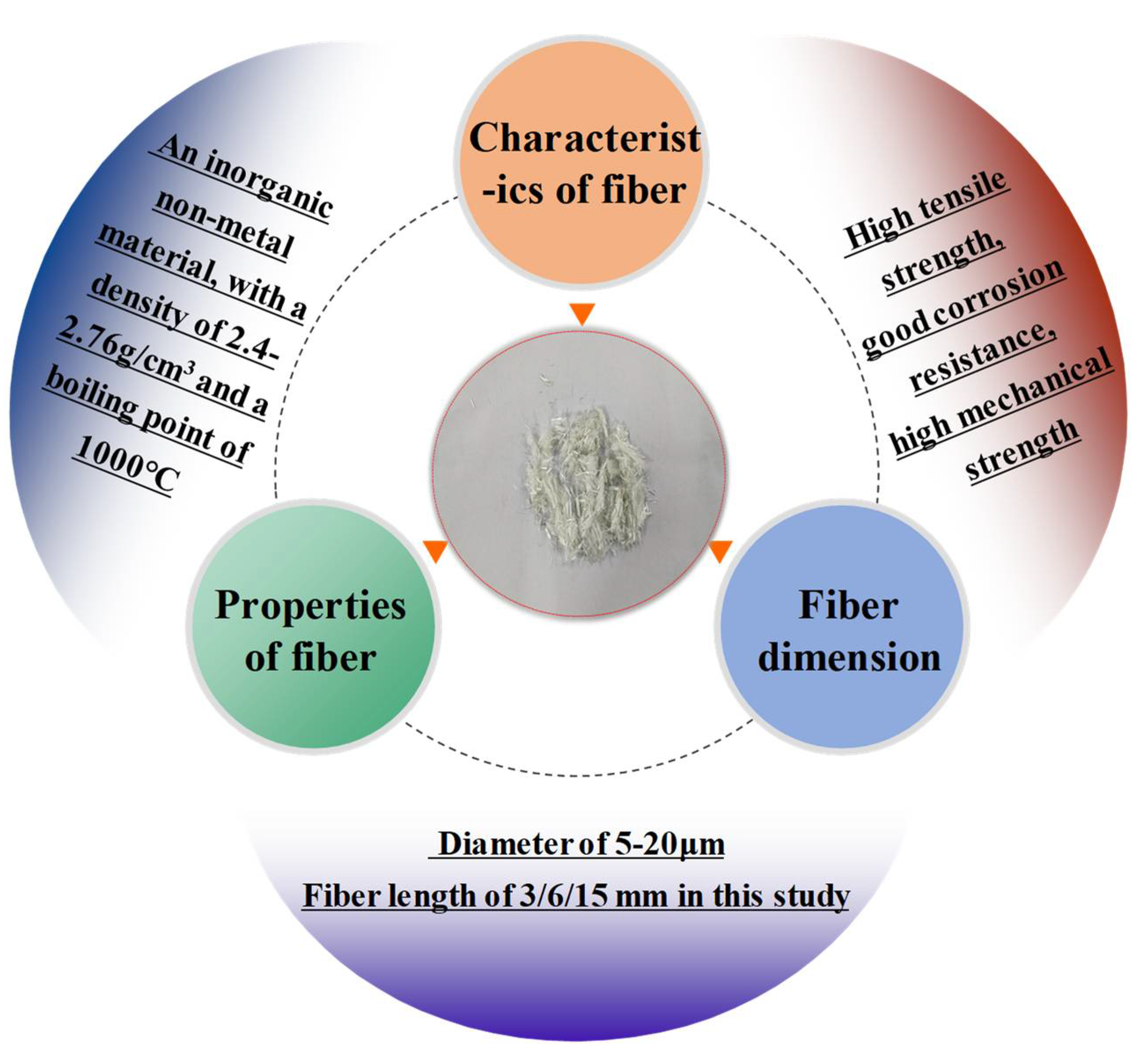
2.1.1. Glass Fibers
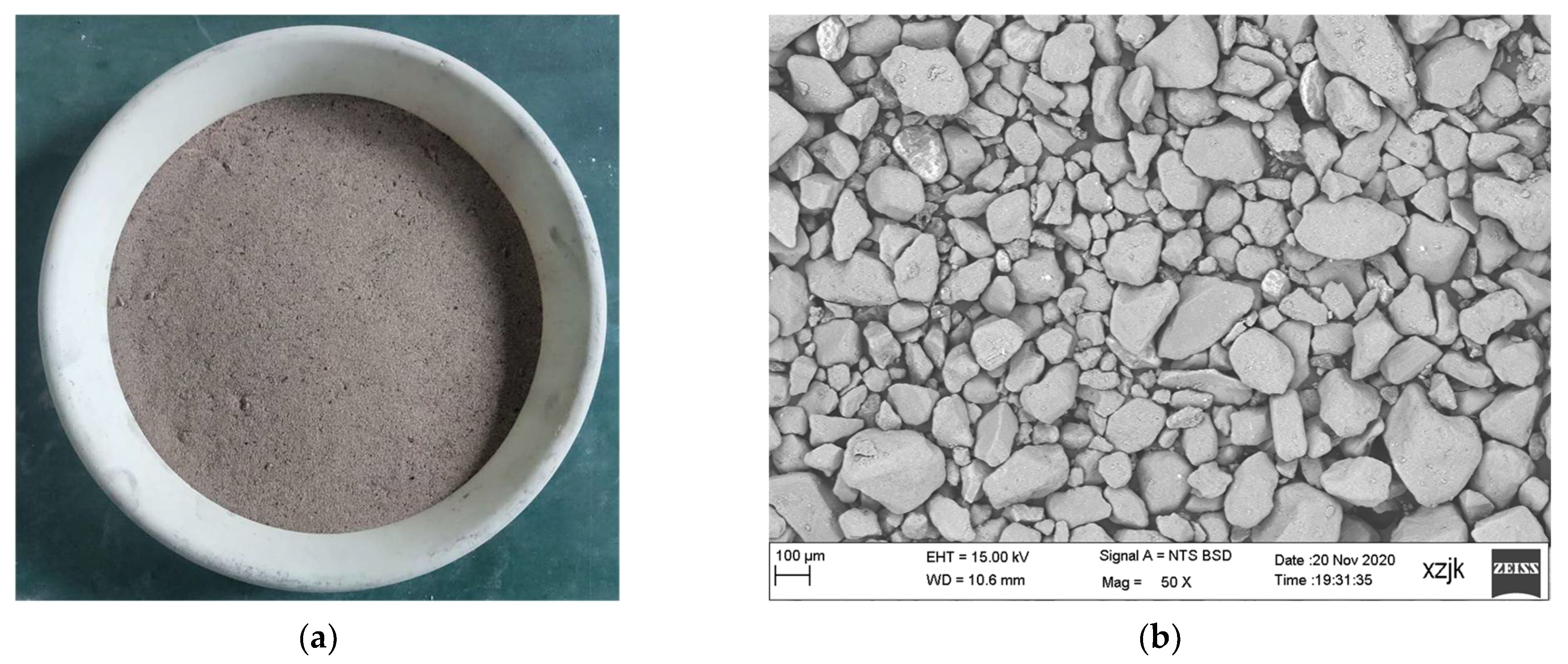
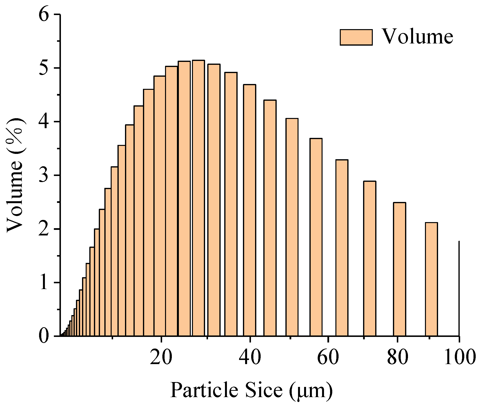
2.1.2. Aeolian Sand
2.1.3. Cement
2.1.4. Fly Ash
2.2. Mix Ratios
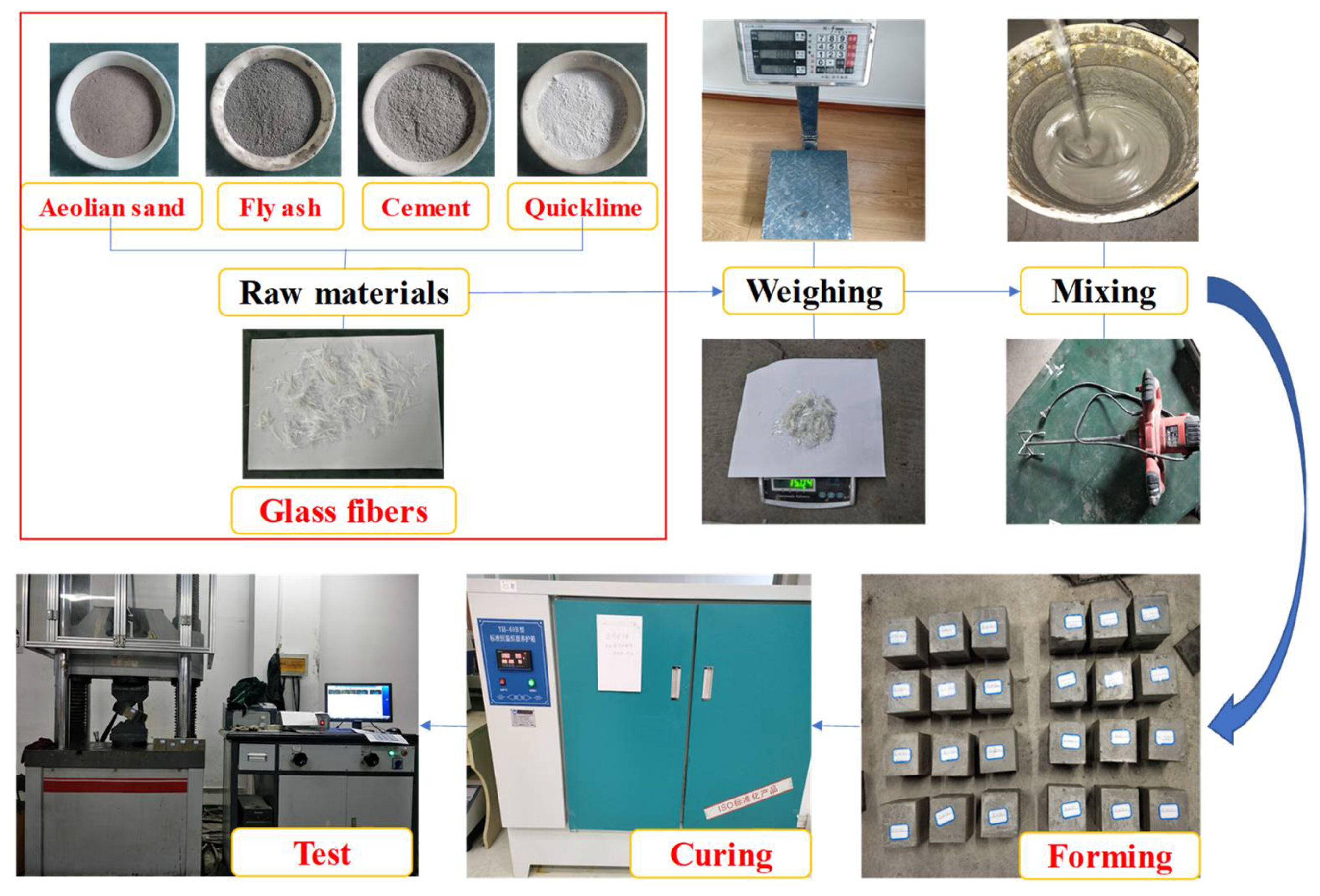
2.3. Preparation of Specimens
2.4. Experimental Method
- (1)
- Mechanical Performance Testing
- (2)
- Microstructural Observations
3. Experimental Results
3.1. Macroscopic Performance Testing
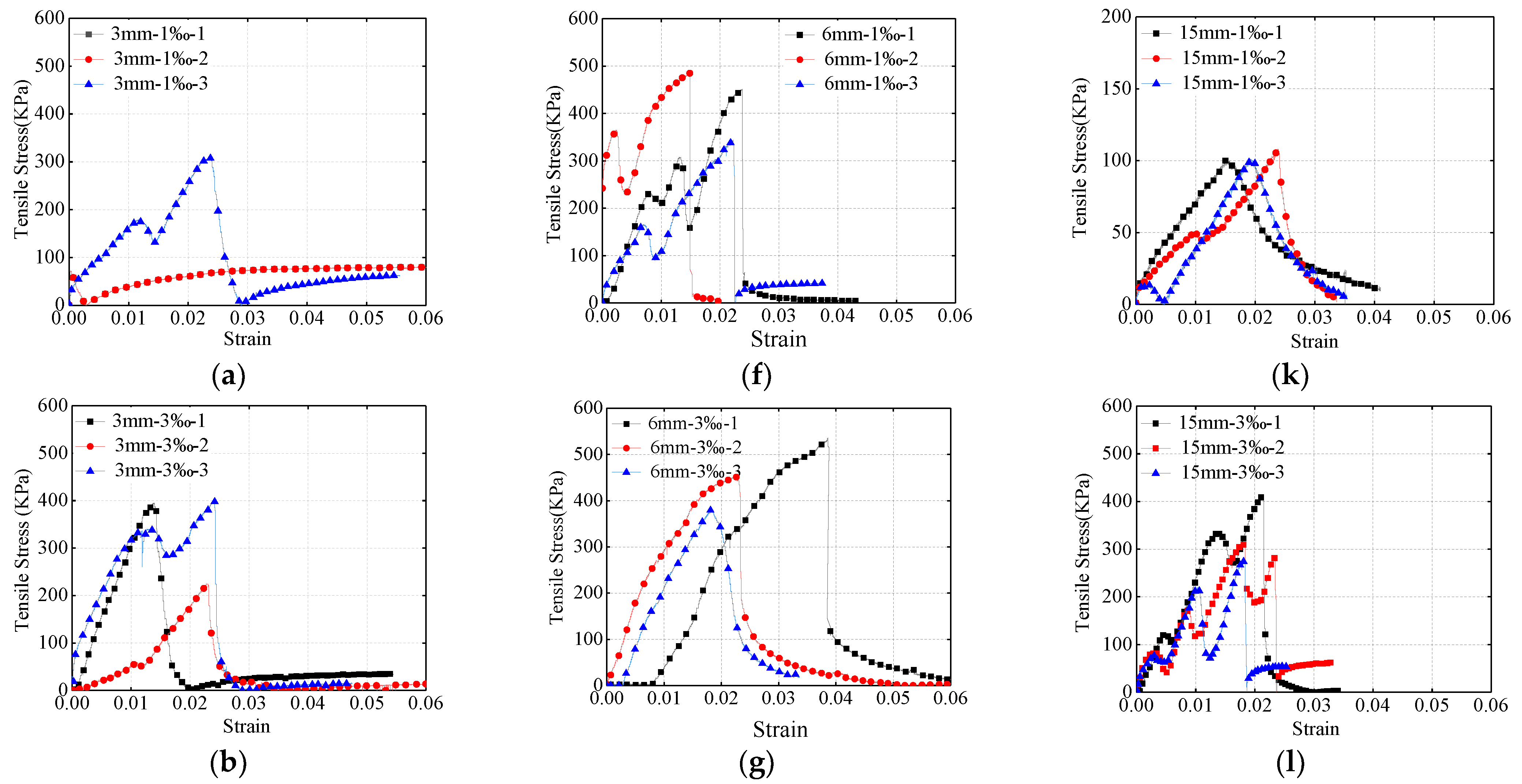
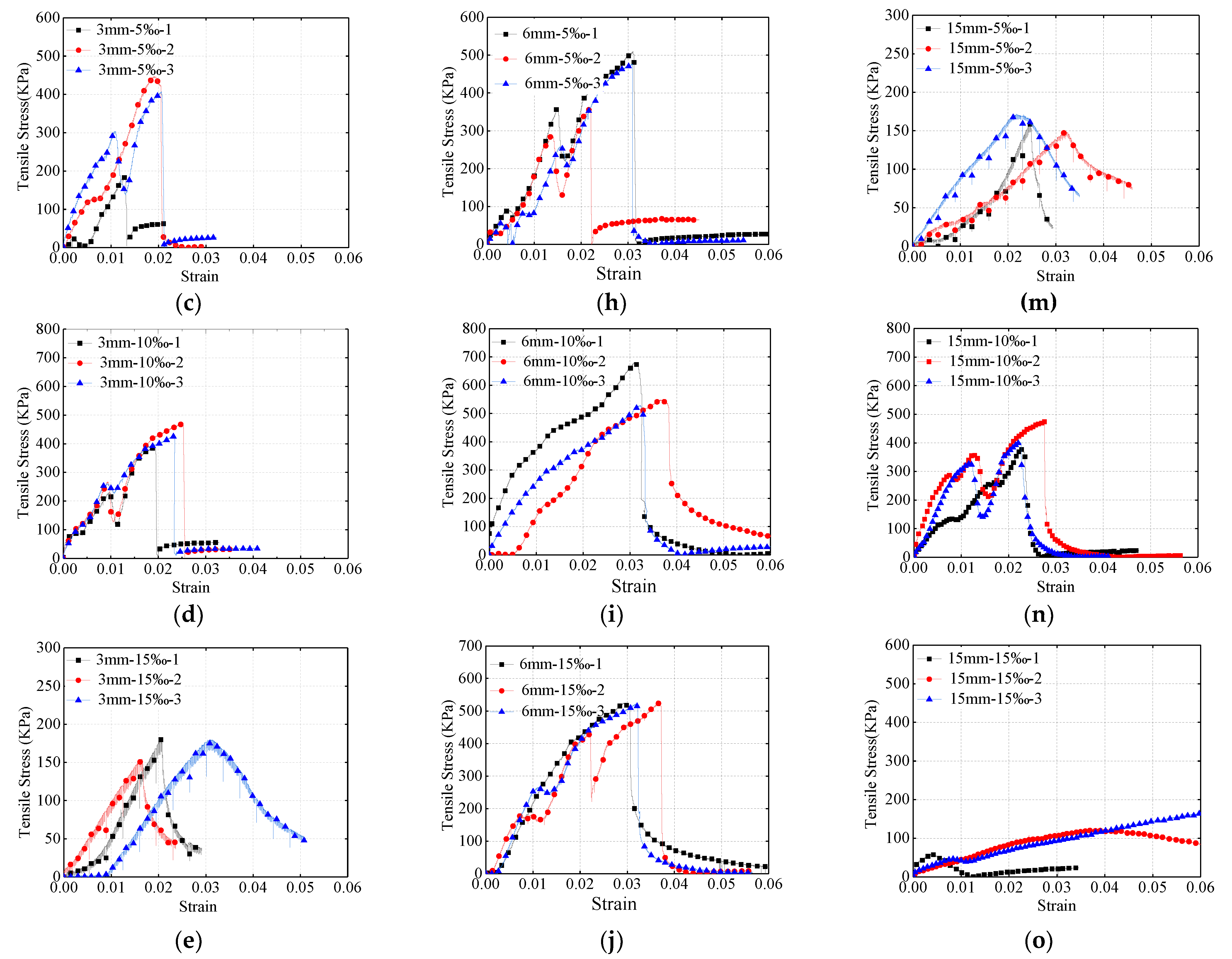
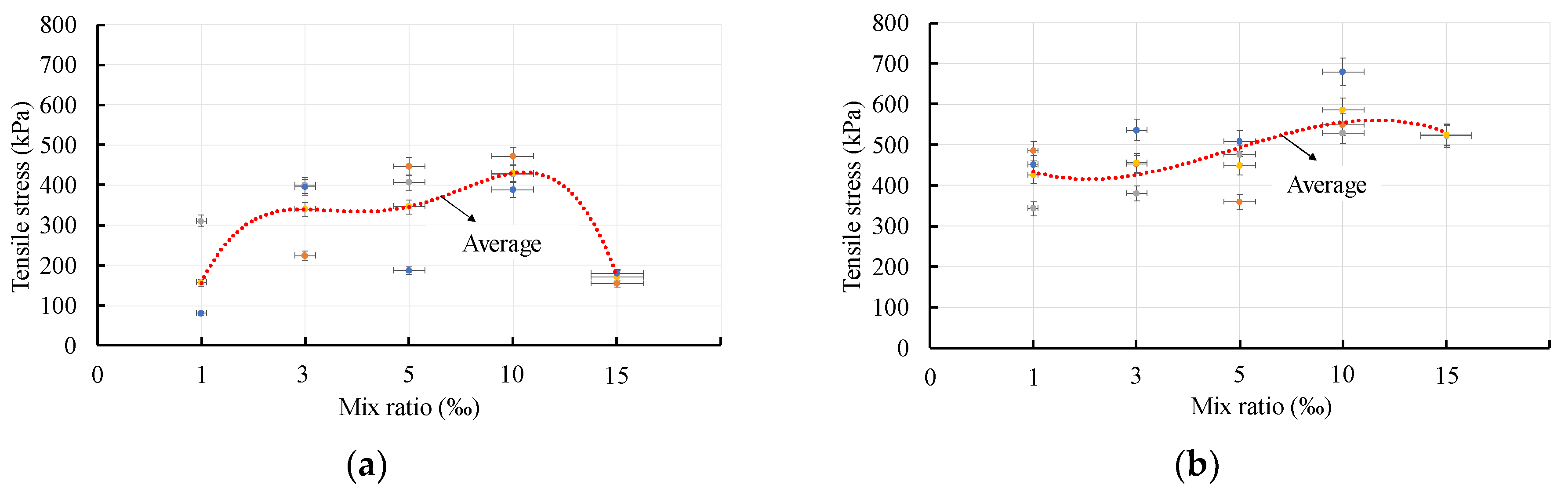
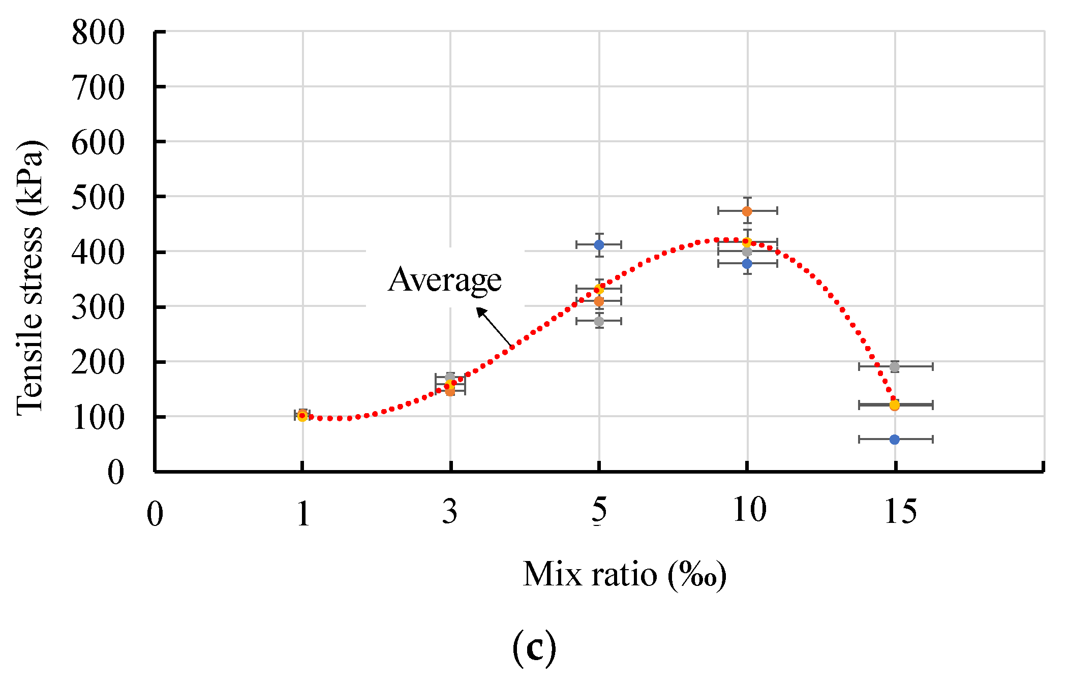
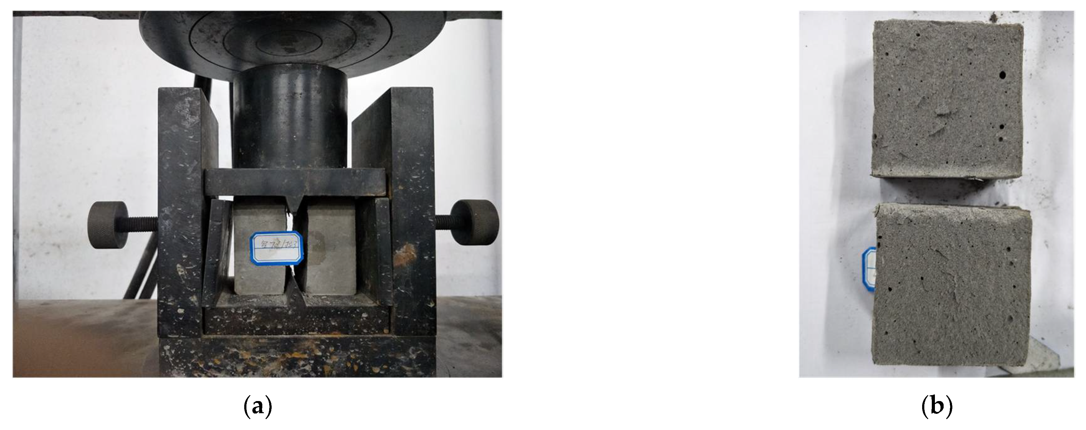
3.1.1. Tensile Strength
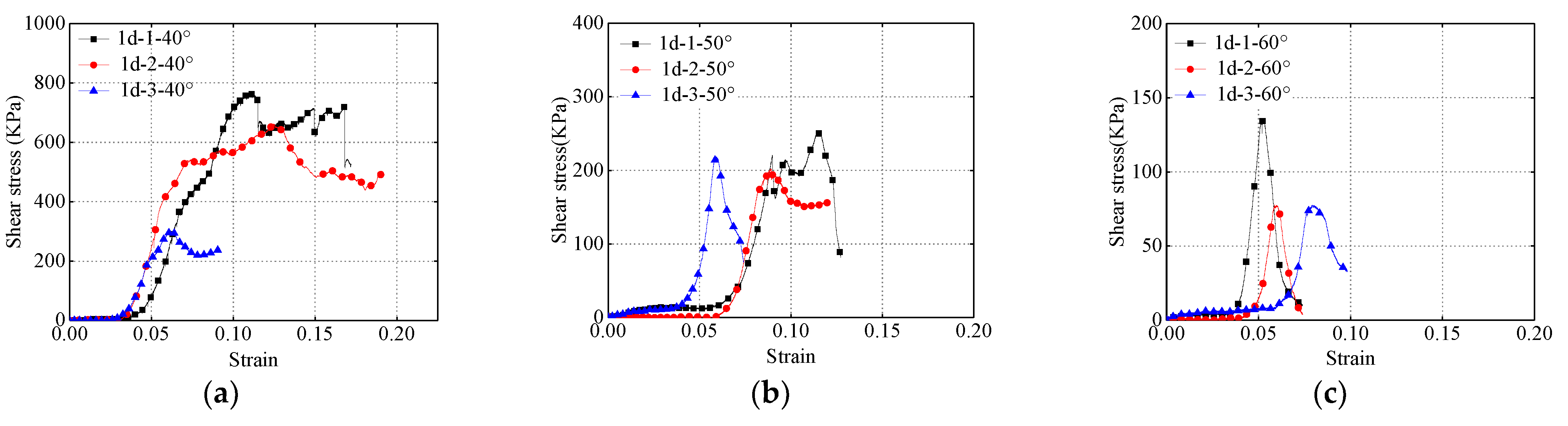
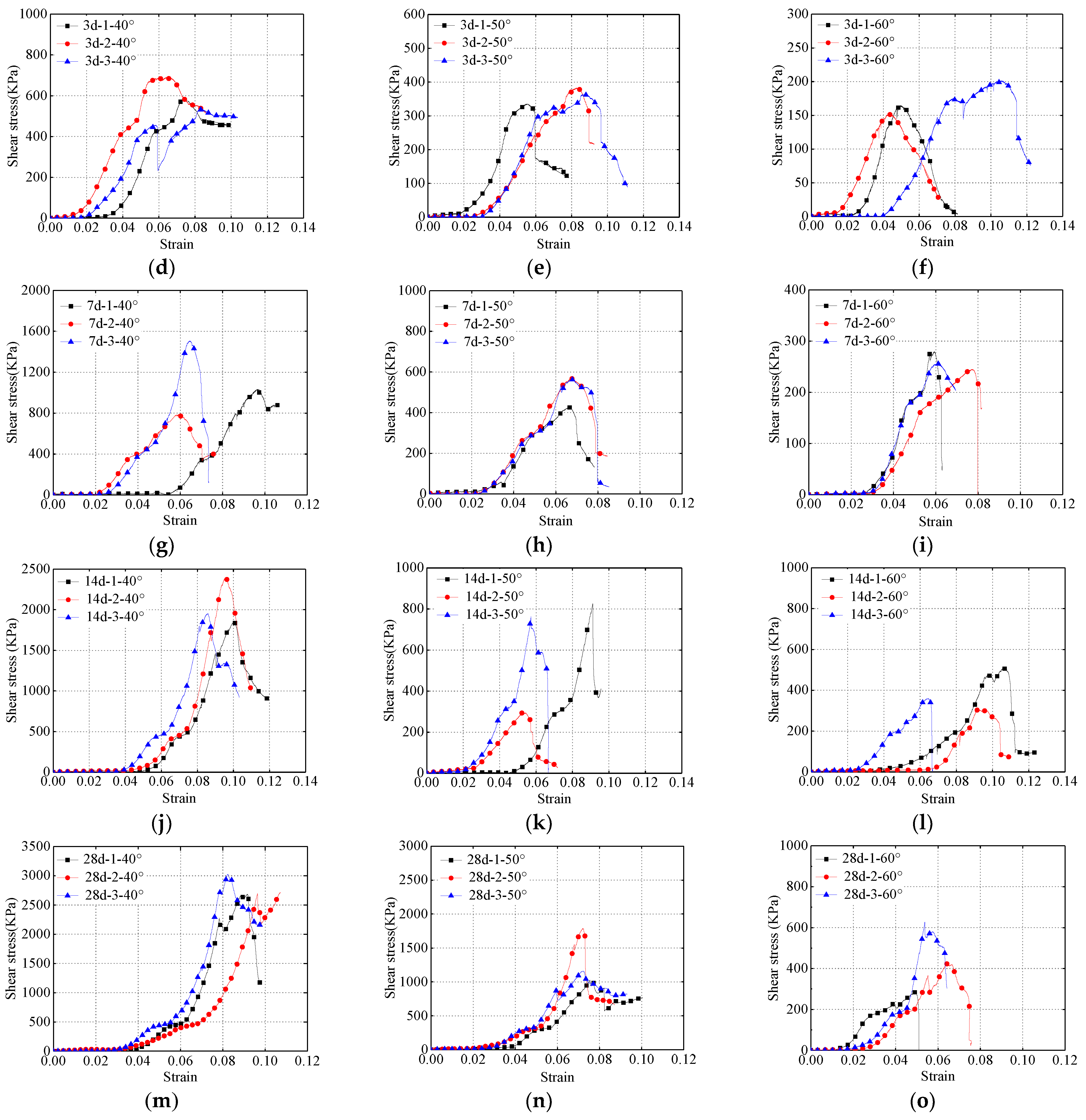
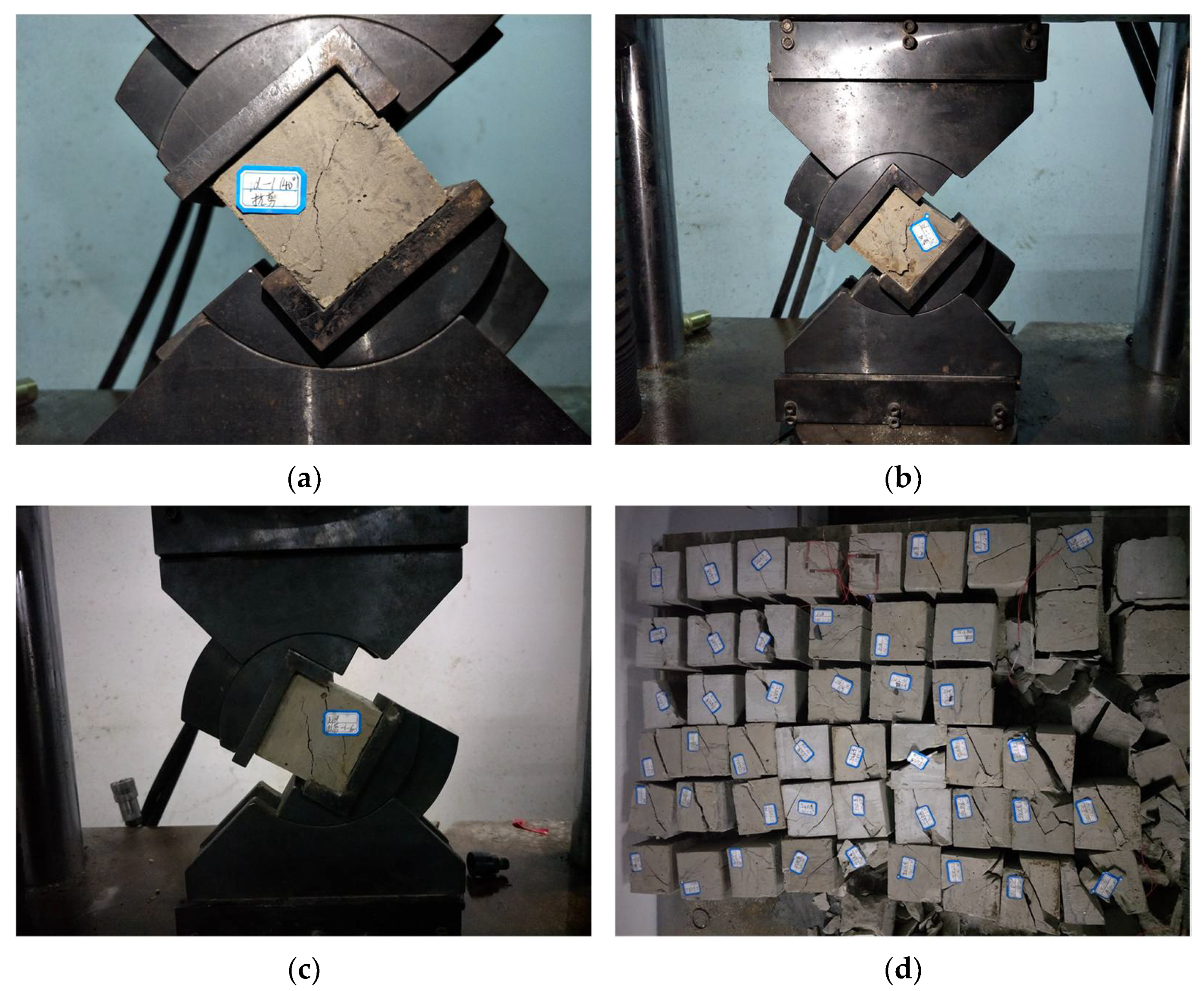
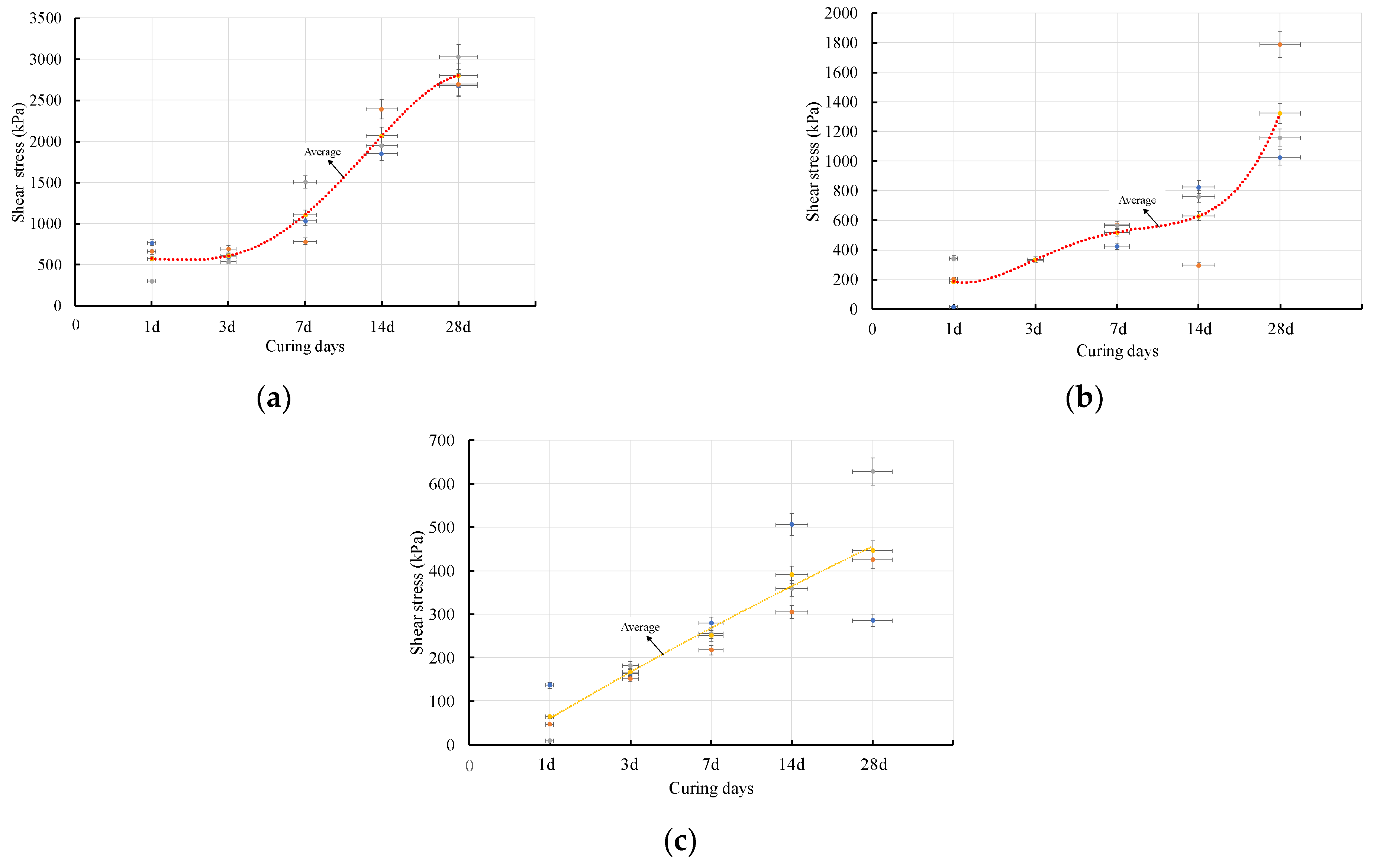
3.1.2. Shear Strength
3.2. Microstructural Characteristics
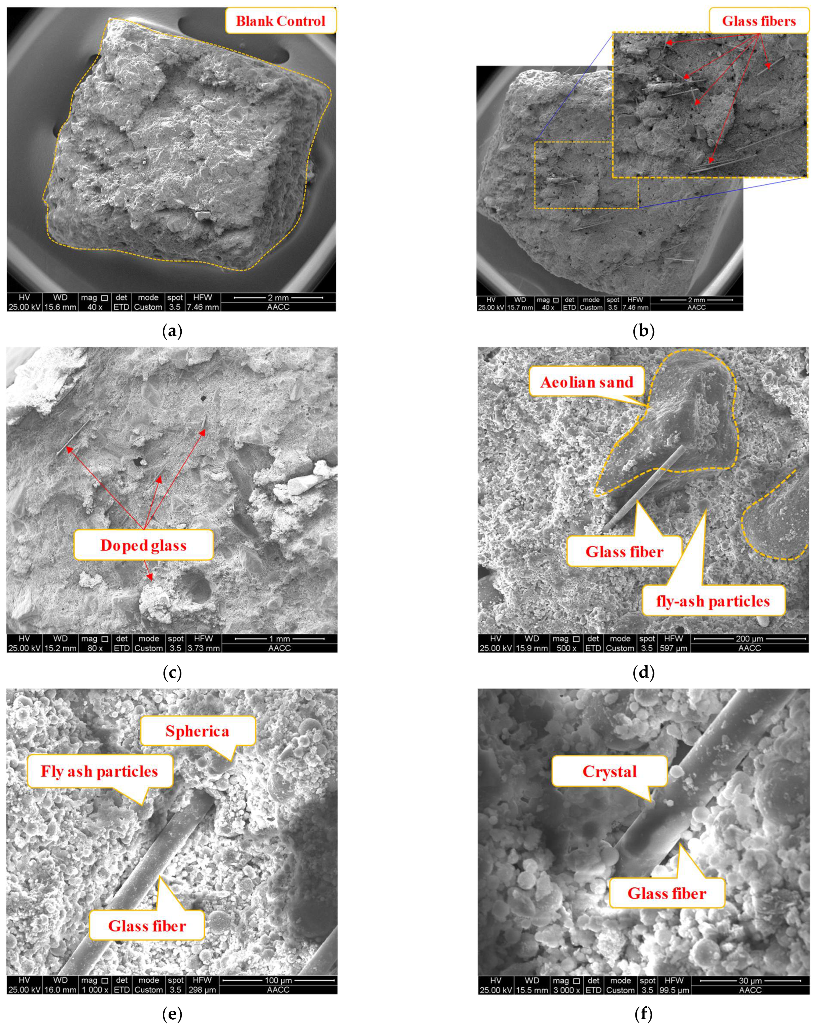
3.2.1. Microscopic Characteristics of Tensile Strength
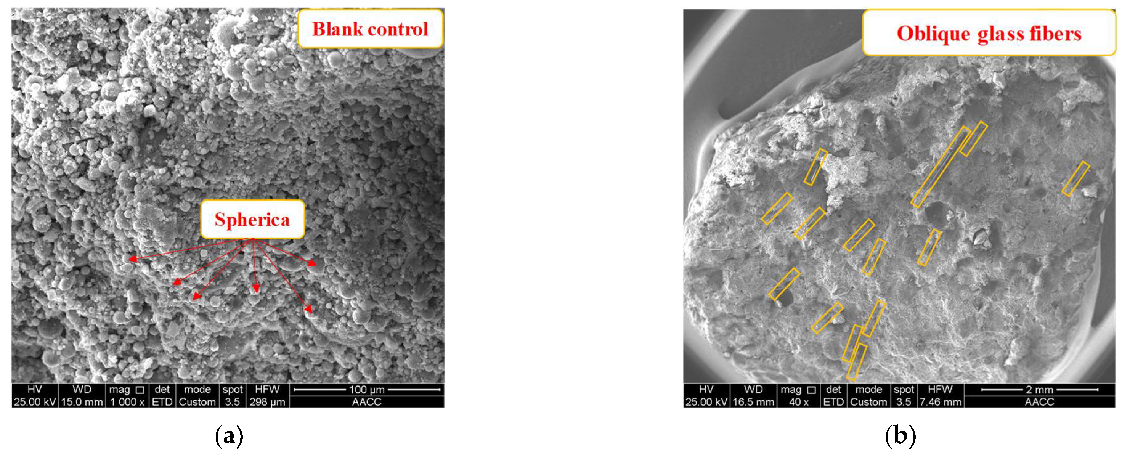
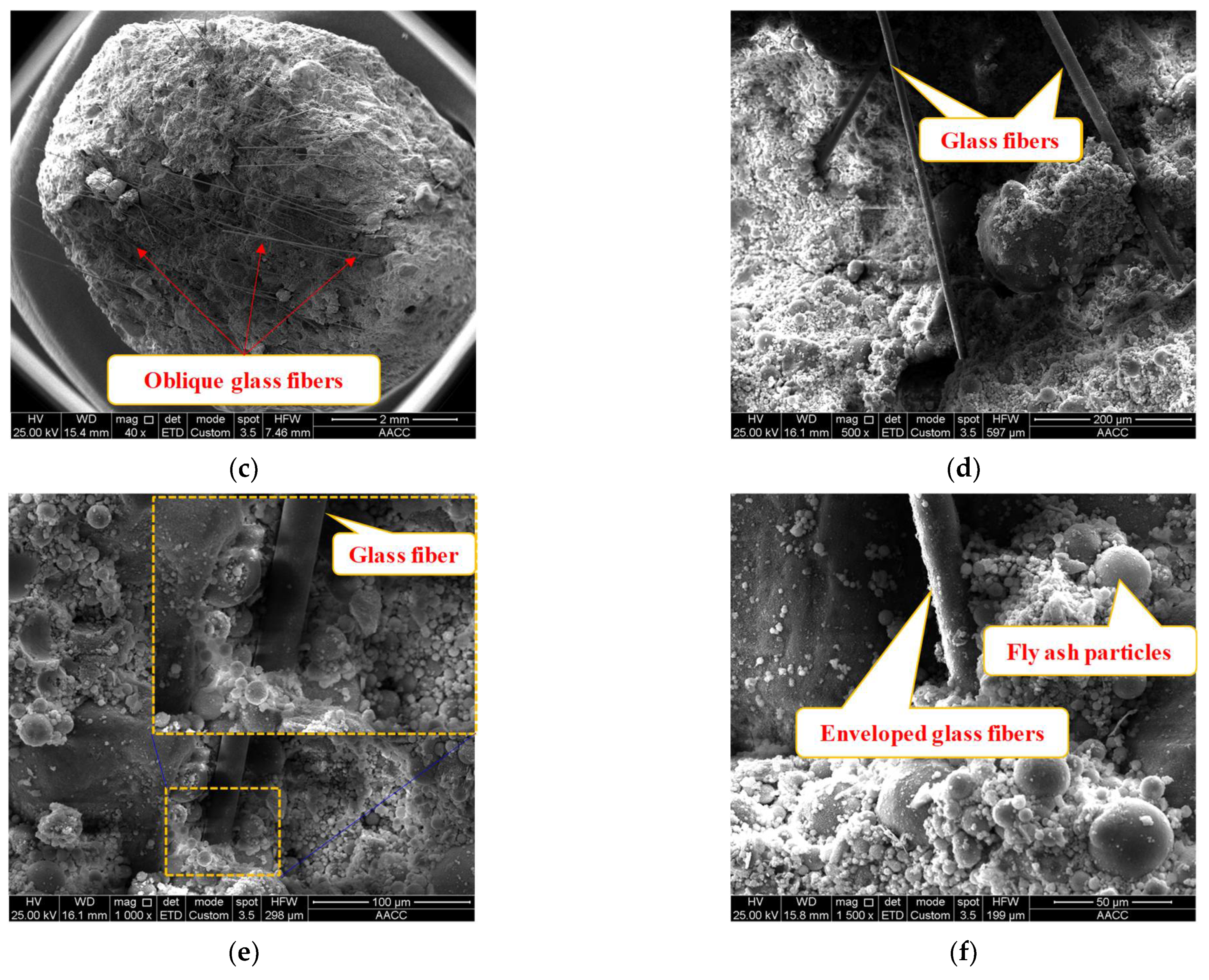
3.2.2. Microscopic Characteristics of Shear Strength
4. Discussion
4.1. Elaboration of a Mechanical Model of Glass Fibers’ Effect
4.2. Mechanism of Doped Glass Fibers’ Effect on the Mechanical Performance of Shotcrete Specimens
5. Conclusions
- (1)
- The physical properties of the glass fiber-doped shotcrete material were tested, including the particle size and EDS analyses of aeolian sand and fly ash raw materials. The main chemical compositions of cement and fly ash were determined.
- (2)
- The tensile and shear strengths of the shotcrete materials varied significantly after their doping by glass fibers with different lengths and different mix ratios. At the doped glass fibers’ length of 3 mm, the highest tensile strength of 429 kPa was reached at a mix ratio of 10‰, exceeding that of a 1‰ mix ratio by 175%. Similarly, at the doped glass fibers’ lengths of 6 and 15 mm, the peak tensile strengths of the shotcrete material were 585 and 417 kPa, respectively. These were higher than the lowest peak tensile strengths of the undoped shotcrete specimens by 37.3% and 309.8%, respectively. Moreover, at a shear angle of 50°, the mechanical performance of the fiber-doped shotcrete material increased continuously as the curing age increased. The shear strength increased most dramatically as the curing age increased from 14 to 28 d.
- (3)
- The microstructure of the doped shotcrete specimens was observed by SEM. It was found that the doped glass fibers in the shotcrete specimens were intertwined with each other. The fly ash particles were embedded into the aeolian sand particles, partially filling the pores in shotcrete specimens. This microstructure was conducive to stress transfer within the specimens, improving the shotcrete specimens’ mechanical strength. The glass fibers were tightly enveloped by the shotcrete material particles, connecting the particles of different components into a whole, thus improving the mechanical strength of the shotcrete material.
- (4)
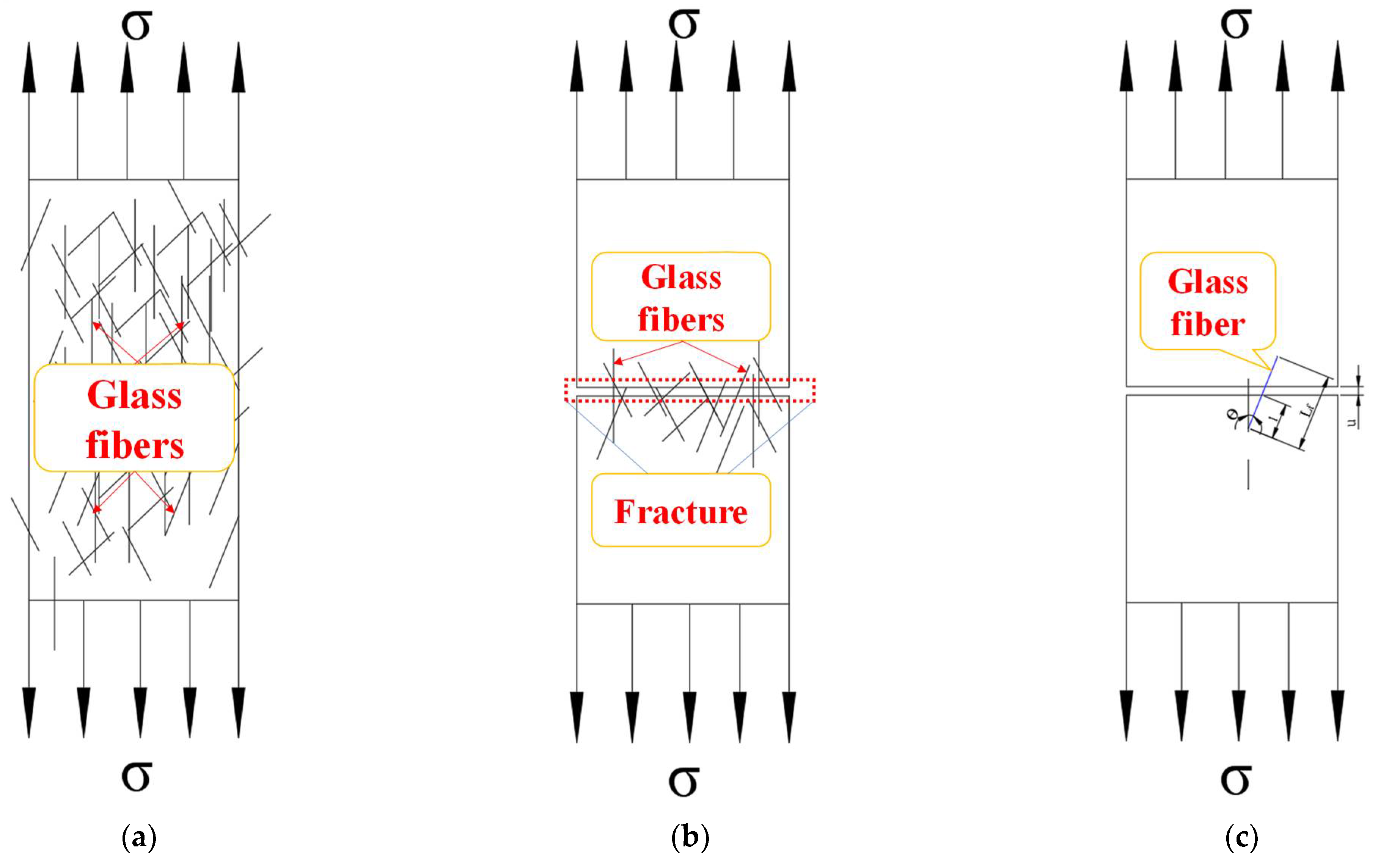
- A 2D simplified mechanical model was constructed for the glass fibers distributed within the shotcrete material. The compound stress of the shotcrete material was the sum of stresses borne by the shotcrete material itself and the bridging stresses exerted by the glass fibers. We also established the relationships of the compound stress in the doped shotcrete material versus fiber embedment length, embedment angle, and cross-sectional area. The functional relationships thus derived lay the basis for a quantitative assessment of the doped glass fibers’ effect on the mechanical performance of shotcrete materials.
Author Contributions
Funding
Data Availability Statement
Acknowledgments
Conflicts of Interest
References
- Bai, X.; Ding, H.; Lian, J.; Ma, D.; Yang, X.; Sun, N.; Xue, W.; Chang, Y. Coal production in China: Past, present, and future projections. Int. Geol. Rev. 2017, 60, 535–547. [Google Scholar] [CrossRef]
- Lin, B.-Q.; Liu, J.-H. Estimating coal production peak and trends of coal imports in China. Energy Policy 2010, 38, 512–519. [Google Scholar] [CrossRef]
- Yu, B.; Tai, Y.; Gao, R.; Yao, Q.L.; Li, Z.; Xia, H.C. The sustainable development of coal mines by new cutting roof technology. R. Soc. Open Sci. 2020, 7, 191913. [Google Scholar] [CrossRef] [PubMed]
- Miao, X.X.; Zhang, J.X.; Guo, G.L. Study on waste-filling method and technology in fully-mechanized coal mining. J. China Coal Soc. 2010, 35, 1–6. [Google Scholar]
- Li, M.; Zhang, J.; Zhou, N.; Huang, Y. Effect of Particle Size on the Energy Evolution of Crushed Waste Rock in Coal Mines. Rock Mech. Rock Eng. 2017, 50, 1347–1354. [Google Scholar] [CrossRef]
- Sirdesai, N.; Singh, T.N.; Ranjith, P.; Singh, R. Effect of Varied Durations of Thermal Treatment on the Tensile Strength of Red Sandstone. Rock Mech. Rock Eng. 2016, 50, 205–213. [Google Scholar] [CrossRef]
- Li, B.; Zhou, N.; Qi, W.; Li, A.; Cui, Z. Surface Subsidence Control during Deep Backfill Coal Mining: A Case Study. Adv. Civ. Eng. 2020, 2020, 1–12. [Google Scholar] [CrossRef]
- Meng, G.; Li, M.; Wu, Z.; Ma, H.; Wang, Y. The effects of high temperature on the compaction behaviour of waste rock backfill materials in deep coal mines. Bull. Int. Assoc. Eng. Geol. 2019, 79, 845–855. [Google Scholar] [CrossRef]
- He, M.C.; Xie, H.P.; Peng, S.P.; Jiang, Y.D. Study on rock mechanics in deep mining engineering. Chin. J. Rock Mech. Eng. 2005, 24, 2803–2813. [Google Scholar]
- Zhu, C.L.; Zhang, J.X.; Zhou, N.; Li, M.; He, Z.W. Effects of Doping Glass Fibers on the Early Strength of Sand-Based Ce-mented Paste Backfill for Solid Wastes Disposal in a Coal Mine. Adv. Civ. Eng. 2021, 2021, 5554941. [Google Scholar]
- Zhou, N.; Han, X.; Zhang, J.; Li, M. Compressive deformation and energy dissipation of crushed coal gangue. Powder Technol. 2016, 297, 220–228. [Google Scholar] [CrossRef]
- Xuan, D.; Xu, J. Longwall surface subsidence control by technology of isolated overburden grout injection. Int. J. Min. Sci. Technol. 2017, 27, 813–818. [Google Scholar] [CrossRef]
- Lei, K.; Pan, H.; Lin, C. A landscape approach towards ecological restoration and sustainable development of mining areas. Ecol. Eng. 2016, 90, 320–325. [Google Scholar] [CrossRef]
- Yu, Y.; Zhang, L.; Lu, J.; Chen, D.; Zhao, X.; Liu, L. Research on the Evolution Characteristics of Floor Stress and Reasonable Layout of Roadways in Deep Coal Mining. Geofluids 2021, 2021, 6631444. [Google Scholar] [CrossRef]
- Xie, H.P.; Gao, F.; Ju, Y.; Gao, M.; Zhang, Z.R.; Gao, Y.N. Quantitative definition and investigation of deep mining. J. China Coal Soc. 2015, 40, 1–10. [Google Scholar]
- Guo, G.-L.; Zhu, X.-J.; Zha, J.-F.; Wang, Q. Subsidence prediction method based on equivalent mining height theory for solid backfilling mining. Trans. Nonferrous Met. Soc. China 2014, 24, 3302–3308. [Google Scholar] [CrossRef]
- Zhu, C.; Zhang, J.; Zhou, N.; Li, M.; Guo, Y. Permeability of Sand-Based Cemented Backfill under Different Stress Conditions: Effects of Confining and Axial Pressures. Geofluids 2021, 2021, 6657662. [Google Scholar] [CrossRef]
- Salesa, A.; Perez-Benedicto, J.A.; Colorado-Aranguren, D.; Lopez-Julian, P.L.; Esteban, L.M.; Sanz-Balduz, L.J.; Saez-Hostaled, J.L.; Ramis, J. Olivares Physico—Mechanical properties of multi—Recycled concrete from precast concrete industry. J. Clean. Prod. 2017, 141, 248–255. [Google Scholar] [CrossRef]
- Meng, X.; Jiang, X.; Li, Z.; Wang, J.; Cooper, K.M.; Xie, Z. Responses of macroinvertebrates and local environment to short-term commercial sand dredging practices in a flood-plain lake. Sci. Total Environ. 2018, 631–632, 1350–1359. [Google Scholar] [CrossRef]
- Li, X.; Zhang, Q.; Xu, C.-Y.; Ye, X. The changing patterns of floods in Poyang Lake, China: Characteristics and explanations. Nat. Hazards 2014, 76, 651–666. [Google Scholar] [CrossRef]
- Xiao, M.; Ju, F.; He, Z.-Q. Research on shotcrete in mine using non-activated waste coal gangue aggregate. J. Clean. Prod. 2020, 259, 120810. [Google Scholar] [CrossRef]
- Yan, H.; Zhang, J.X.; Zhou, N.; Li, M. Triaxial compression behaviour of gangue solid wastes under effects of particle size and confining pressure. Sci. Total Environ. 2020, 711, 135029. [Google Scholar] [CrossRef]
- Yan, H.; Zhang, J.; Zhou, N.; Li, M. Application of hybrid artificial intelligence model to predict coal strength alteration during CO2 geological sequestration in coal seams. Sci. Total Environ. 2020, 711, 135029. [Google Scholar] [CrossRef]
- Zhou, N.; Zhang, J.; Ouyang, S.; Deng, X.; Dong, C.; Du, E. Feasibility study and performance optimization of sand-based cemented paste backfill materials. J. Clean. Prod. 2020, 259, 120798. [Google Scholar] [CrossRef]
- Zhou, N.; Ma, H.; Ouyang, S.; Germain, D.; Hou, T. Influential Factors in Transportation and Mechanical Properties of Aeolian Sand-Based Cemented Filling Material. Minerals 2019, 9, 116. [Google Scholar] [CrossRef] [Green Version]
- Ouyang, X.W.; Ye, G.; van Breugel, K. Experimental and numerical evaluation of mechanical properties of interface be-tween filler and hydration products. Constr. Build. Mater. 2017, 135, 538–549. [Google Scholar] [CrossRef]
- Deng, X.J.; Klein, B.; Hallbom, D.J.; de Wit, B.; Zhang, J.X. Influence of Particle Size on the Basic and Time-Dependent Rheo-logical Behaviors of Cemented Paste Backfill. J. Mater. Eng. Perform. 2018, 27, 3478–3487. [Google Scholar] [CrossRef]
- Sucharda, O.; Konečný, P.; Kubosek, J.; Ponikiewski, T.; Doné, P. Finite Element Modelling and Identification of the Material Properties of Fibre Concrete. Procedia Eng. 2015, 109, 234–239. [Google Scholar] [CrossRef] [Green Version]
- Liang, N.H.; Ren, L.X.; Tian, S.; Liu, X.R.; Zhong, Z.L.; Deng, Z.Y.; Yan, R. Study on the Fracture Toughness of Polypropyl-ene-Basalt Fiber-Reinforced Concrete. Int. J. Concr. Struct. Mater. 2021, 15, 35. [Google Scholar] [CrossRef]
- Saini, D.; Oppong, K.; Shafei, B. Investigation of Concrete Constitutive Models for Ultra-High Performance Fi-ber-Reinforced Concrete under Low-Velocity Impact. Int. J. Impact Eng. 2021, 157, 103969. [Google Scholar] [CrossRef]
- Ranjbar, N.; Mehrali, M.; Behnia, A.; Pordsari, A.J.; Mehrali, M.; Alengaram, U.J.; Jumaat, M.Z. A Comprehensive Study of the Polypropylene Fiber Reinforced Fly Ash Based Geopolymer. PLoS ONE 2016, 11, e0147546. [Google Scholar] [CrossRef] [Green Version]
- Ayazian, R.; Abdolhosseini, M.; Firouzi, A.; Li, C.Q. Reliability-based optimization of external wrapping of CFRP on rein-forced concrete columns considering decayed diffusion. Eng. Fail. Anal. 2021, 128, 105592. [Google Scholar] [CrossRef]


| Diameter | Elongation at Break | Young Modulus | Density | Tensile Strength |
|---|---|---|---|---|
| 0.3–0.4 mm | 3.3–3.6% | 7300–8600 MPa | 2.4–2.76 g/cm3 | 3100–4650 MPa |
| Element | Weight Percent, wt% | Atomic Percent, at% |
|---|---|---|
| O | 46.61 | 61.04 |
| Si | 20.59 | 15.36 |
| Al | <10 | 11.65 |
| Fe | 11.46 | <10 |
| Other elements | <10 | <10 |
| Element | Weight Percent, wt% | Atomic Percent, at% |
|---|---|---|
| O | 43.36 | 45.77 |
| C | 27.18 | 38.22 |
| Si | 11.99 | 7.21 |
| Other elements | <10 | <10 |
| Sample Designation | Mix Ratio, ‰ | Tensile Strength, kPa | Average Tensile Strength, kPa | Variance | Standard Deviation, % |
|---|---|---|---|---|---|
| Fiber length of 3 mm | |||||
| A1 | 1 | 80 | 156 | 11,756 | 108 |
| A2 | 80 | ||||
| A3 | 310 | ||||
| B1 | 3 | 395 | 339 | 6653 | 81 |
| B2 | 224 | ||||
| B3 | 399 | ||||
| C1 | 5 | 186 | 346 | 13,066 | 114 |
| C2 | 446 | ||||
| C3 | 406 | ||||
| D1 | 10 | 389 | 429 | 1122 | 33 |
| D2 | 471 | ||||
| D3 | 427 | ||||
| E1 | 15 | 179 | 171 | 3626 | 60 |
| E2 | 154 | ||||
| E3 | 180 | ||||
| Fiber length of 6 mm | |||||
| F1 | 1 | 451 | 426 | 3626 | 60 |
| F2 | 484 | ||||
| F3 | 343 | ||||
| G1 | 3 | 536 | 456 | 4046 | 63 |
| G2 | 452 | ||||
| G3 | 380 | ||||
| H1 | 5 | 509 | 448 | 4142 | 64 |
| H2 | 359 | ||||
| H3 | 476 | ||||
| I1 | 10 | 680 | 585 | 4509 | 67 |
| I2 | 548 | ||||
| I3 | 529 | ||||
| J1 | 15 | 524 | 523 | 2.8 | 1.6 |
| J2 | 525 | ||||
| J3 | 521 | ||||
| Fiber length of 15 mm | |||||
| K1 | 1 | 100 | 102 | 9.5 | 3 |
| K2 | 107 | ||||
| K3 | 101 | ||||
| L1 | 3 | 159 | 159 | 96 | 9.7 |
| L2 | 147 | ||||
| L3 | 171 | ||||
| M1 | 5 | 413 | 333 | 3416 | 58 |
| M2 | 311 | ||||
| M3 | 275 | ||||
| N1 | 10 | 378 | 418 | 1712 | 41 |
| N2 | 475 | ||||
| N3 | 401 | ||||
| P1 | 15 | 58.9 | 123 | 2957 | 54 |
| P2 | 121 | ||||
| P3 | 192 | ||||
| Specimen Designation | Curing Age, Days | Shear Angle, Degrees | Shear Strength, kPa | Average Shear Strength, kPa | Standard Deviation, % |
|---|---|---|---|---|---|
| A1 | 1 | 40 | 766 | 575 | 200 |
| A2 | 661 | ||||
| A3 | 299 | ||||
| A4 | 50 | 14 | 186 | 134 | |
| A5 | 202 | ||||
| A6 | 342 | ||||
| A7 | 60 | 136 | 64 | 53 | |
| A8 | 47 | ||||
| A9 | 8.5 | ||||
| B1 | 3 | 40 | 596 | 608 | 63 |
| B2 | 691 | ||||
| B3 | 537 | ||||
| B4 | 50 | 335 | 333 | 2.9 | |
| B5 | 334 | ||||
| B6 | 328 | ||||
| B7 | 60 | 164 | 166 | 12.7 | |
| B8 | 151 | ||||
| B9 | 182 | ||||
| C1 | 7 | 40 | 1032 | 1108 | 299 |
| C2 | 784 | ||||
| C3 | 1507 | ||||
| C4 | 50 | 425 | 519 | 66 | |
| C5 | 568 | ||||
| C6 | 565 | ||||
| C7 | 60 | 279 | 250 | 25 | |
| C8 | 217 | ||||
| C9 | 256 | ||||
| D1 | 14 | 40 | 1854 | 2066 | 234 |
| D2 | 2393 | ||||
| D3 | 1950 | ||||
| D4 | 50° | 825 | 628 | 235 | |
| D5 | 297 | ||||
| D6 | 762 | ||||
| D7 | 60 | 506 | 390 | 85 | |
| D8 | 305 | ||||
| D9 | 359 | ||||
| E1 | 28 | 40° | 2683 | 2802 | 158 |
| E2 | 2696 | ||||
| E3 | 3026 | ||||
| E4 | 50 | 1025 | 1323 | 332 | |
| E5 | 1787 | ||||
| E6 | 1158 | ||||
| E7 | 60 | 286 | 446 | 140 | |
| E8 | 425 | ||||
| E9 | 627 |
Publisher’s Note: MDPI stays neutral with regard to jurisdictional claims in published maps and institutional affiliations. |
© 2021 by the authors. Licensee MDPI, Basel, Switzerland. This article is an open access article distributed under the terms and conditions of the Creative Commons Attribution (CC BY) license (https://creativecommons.org/licenses/by/4.0/).
Share and Cite
Zhu, C.; Zhou, N.; Guo, Y.; Li, M.; Cheng, Q. Effect of Doped Glass Fibers on Tensile and Shear Strengths and Microstructure of the Modified Shotcrete Material: An Experimental Study and a Simplified 2D Model. Minerals 2021, 11, 1053. https://doi.org/10.3390/min11101053
Zhu C, Zhou N, Guo Y, Li M, Cheng Q. Effect of Doped Glass Fibers on Tensile and Shear Strengths and Microstructure of the Modified Shotcrete Material: An Experimental Study and a Simplified 2D Model. Minerals. 2021; 11(10):1053. https://doi.org/10.3390/min11101053
Chicago/Turabian StyleZhu, Cunli, Nan Zhou, Yaben Guo, Meng Li, and Qiangqiang Cheng. 2021. "Effect of Doped Glass Fibers on Tensile and Shear Strengths and Microstructure of the Modified Shotcrete Material: An Experimental Study and a Simplified 2D Model" Minerals 11, no. 10: 1053. https://doi.org/10.3390/min11101053
APA StyleZhu, C., Zhou, N., Guo, Y., Li, M., & Cheng, Q. (2021). Effect of Doped Glass Fibers on Tensile and Shear Strengths and Microstructure of the Modified Shotcrete Material: An Experimental Study and a Simplified 2D Model. Minerals, 11(10), 1053. https://doi.org/10.3390/min11101053