Article

Embankment Displacement PLAXIS Simulation and Microstructural Behavior of Treated-Coal Gangue

1
College of Energy and Transportation Engineering, Inner Mongolia Agricultural University, Hohhot 010018, China
2
Department of Civil & Environmental Engineering, University of Waterloo, Waterloo, ON N2L 3G1, Canada
3
Waterloo Collegiate Institute, Waterloo, ON N2L 3P2, Canada
*
Author to whom correspondence should be addressed.
Minerals 2020, 10(3), 218; https://doi.org/10.3390/min10030218
Submission received: 11 January 2020 / Revised: 24 February 2020 / Accepted: 26 February 2020 / Published: 28 February 2020

Abstract

:
The purpose of this study is to investigate the displacement of coal gangue filling material in road construction and microstructural behavior of treated coal gangue by considering the environmental factors of aqueous solutions with different acidity. The displacement analysis of the coal gangue embankment model has been done by means of the finite element method PLAXIS. Furthermore, using the scanning electron microscope, the energy dispersive system, and the Raman spectrometer to analyze the microscopic mechanism in the view of microstructure, elements, the integrity of carbon structure and the stability of chemical bonds of coal gangue. The results show that the larger displacement of the treated coal gangue subgrade is within 4.0 m below the top of the subgrade, and the maximum displacement value is about 7 mm, which is less than the displacement of untreated coal gangue sample. While the treated A-CG and T-CG grain size, surface area and internal friction angle increase, the unstable carbon structure is destroyed, so its shear strength, compression performance, and consolidation effect are improved. S-CG particles are coated with Na-Si-Al gel, which enhances the density, viscosity and shear strength, thus ensuring the stability of the coal gangue subgrade. The treated coal gangue subgrade slope foot displacement, boundary shear stress and safety factor are all meet the specification requirements.

1. Introduction

Coal gangue (CG), a mine tailing discharged during the process of coal mining and washing, is a kind of black-gray rock with low carbon content and it is harder than coal in the formation of the coal. Piled-up waste CG consumes land resources, seriously pollutes vegetation, soil, and water bodies [1,2,3,4,5]. In order to enhance the utilization rate of CG, many scholars have studied the properties of CG and found the performance of CG is reliable when using it directly or combined with other road materials [6,7,8,9,10,11]. The main factors affecting the subgrade stability are the components of the coal gangue, the additive materials, the optimum water contents, the subgrade structures, the construction compaction, loads, etc. For the purpose of improving its stability, a huge number of studies start from physical methods, by controlling the filling height, impact and strong compaction, or incorporation additives, such as lime, cement, fly ash, red mud, or asphalt [12,13,14,15,16]. However, coal gangue with a large amount of organic matter can be easily affected by different acidity solutions. Thus, its chemical reactions and unstable properties usually lead to damage to the engineering structure [17,18,19,20,21,22]. Some scholars using X-ray diffraction (XRD), X-ray fluorescence (XRF), Fourie transform infrared (FTIR), Scanning Electron Microscope (SEM), Energy Dispersive Spectrometer (EDS), and other micro-research methods to study the influences of different acid and alkali materials, pH, concentration, temperatures, treatment time, etc., and also study the chemical composition, contents, micro-morphia structure, strength and other changes [20,23,24]. The researchers found that the coal gangue backfilling materials were filled, and the surface was rough and irregular with coarse texture by Scanning Electron Microscope [25,26]. Most of them only focused on the characteristics of coal gangue and did not analyze and explore engineering performance when coal gangue is used as subgrade material. The stability and settlement of embankments over soft soil have been investigated by numerical simulations [27,28,29,30] with the advantages of low cost and easy observation. PLAXIS can be effectively used in the observation of soil settlement and assessment of the stability [31,32]. According to the different filling heights of CG, the impact of settlement and stress change of the embankment model in the construction stage were analyzed by the finite element model [33].
The purpose of this study is to determine the final displacement of road embankment considering filling materials treated in different acidity solutions and evaluate the effect of an aqueous environment. The subgrade displacements, slope foot displacement, interface shear stress, excess pore water pressure, and safety factor during filling stages and consolidation thereafter have been observed by the finite element method using PLAXIS. Morphological and compositional aspects were analyzed by SEM, combined with EDS. The integrity of the carbon structure and the consistency of chemical bonds in the specimen were analyzed by a laser microscope Raman spectrometer. Based on the observation of SEM micro-morphology, EDS energy spectrum, and Raman spectra analysis of the corresponding elements, the internal mechanism of the displacement change of coal gangue roadbed under the influence of different acidity solution environment was explored. It provides theoretical support for the application of coal gangue in subgrade engineering. In addition, the reuse of the present stone waste will contribute to eliminating environmental degradation promoted by numerous waste-dumps in mining areas.

2. Materials and Methods

2.1. Preparation for Samples

The coal gangue used in this study was obtained from the Jinyang Coal Mine in Ordos, China. The main chemical composition (presented in Table 1) of coal gangue was determined by an X-ray fluorescence spectrometer (Axios Pw4400, PANalytical B.V, Almelo, Netherlands) according to ASTM: E 1621-05 [34].
As seen in Table 1, two main oxides SiO2 and Al2O3 account for 78.6%. The CG was crushed, screened, and selected as samples with sizes between 9.5 and 16 mm [35]. Coal gangue contains a large number of oxides, which can react with acid-based solution at a normal temperature to occur exchange ions with each other and produce hardening effect, so commonly used treatment solutions are hydrochloric acid, sulfuric acid, nitric acid, acetic acid, sodium hydroxide, potassium hydroxide, and calcium hydroxide [23]. Therefore, acetic acid (A), tap water (T) and sodium hydroxide (S) with pH 4.5, pH 7.2 and pH 8.5, respectively, were chosen to treat coal gangue samples [36]. CG and solutions were mixed at the mass ratio of 1:1, then the mixture was sealed. Stirred the mixture every other day. The pH value of the soaking solution and the mass loss rate of coal gangue did not change for 15 days according to the previous research [37]. Therefore, in order to allow the specimen to react completely with the solutions, coal gangue was soaked in acetic acid (A-CG), tap water (T-CG) and sodium hydroxide (S-CG) for 15 days. CG without solution treatment was used as a control for the test.

2.2. Test Methods

Acetic acid, tap water, and sodium hydroxide solutions were prepared to simulate the acidity change conditions of the external environment. The coal gangue samples were immersed in acidic, neutral and alkaline solutions for 15 days. The differences between composition and structure on the CG surface of the original sample and the sample after leaching were measured through a scanning electron microscope (ZEISS SUPRATM 55, Carl Zeiss Co., Ltd., Jena, Germany) with an energy dispersive spectrometer which was operated under an acceleration voltage of 30 kV. The element distribution was analyzed via an X–Max energy spectrometer (X–Max80, Oxford Instruments, Oxford, England) with 80 mm2 detector crystal, 2000 times amplification factor, and 129 eV resolution was selected to further verify the authenticity of the composition. The changes in the carbon structure and chemical bonds in different coal gangue samples and the resulting in changes in the generation and properties of new substances were observed by the laser microscope Raman spectrometer (Renishaw in Via, Renishaw, England).

2.3. Mohr-Coulomb Model

PLAXIS software is a general geotechnical finite element computing software that was introduced by PLAXIS B.V. (Delft, Netherland), now widely used in the finite element analysis of various complex geotechnical projects. Its computational function is powerful and has a wide range of applications, and can be used in plastic analysis of foundation, excavation, support, loading, etc., the solidification analysis of the problems involving the growth and dissipation of super-porous pressure, the calculation of seepage and the full-flow coupling analysis of the problems involving water level changes can be carried out by the safety analysis of the issues involved stability. The purpose of this article is to simulate the process of subgrade construction on a clay foundation by means of PLAXIS. The Mohr Coulomb model requires only five parameters, including resilient modulus (E0), Poisson’s ratio (ν), the angle of internal friction (φ), cohesion (c), and dilatancy angle (ψ), which is less than other models [31], so, Mohr Coulomb model was chosen in PLAXIS. Those parameters can be obtained from basic tests according to the test procedure [38] (shown in Table 2). Unsaturated weight and E0 were measured by the density test and the rebound modulus test, respectively. φ and c were measured by the triaxial test. ν and ψ were formed as empirical values. Parameters used in the PLAXIS model are shown in Table 2.
The numerical modeling of the full-scale embankment was performed using a finite element software. The model is based on the construction of a subgrade with a top width of 16m on a soft soil foundation [39]. In order to ensure the stability of the coal gangue subgrade, when the filling height is 8 m, the slope rate should not be steeper than 1:1.5 [24]. Thus, the subgrade model selects the height of 6m and the slope rate of 1:2, and a layer of clay with a depth of 6 m distributed underneath. In this paper, due to the symmetry of the geometric model, the right half is intercepted for analysis. Since it is assumed that the deep compact sand layer will not deform according to the code [40], when the bottom of the clay layer is a dense sand layer, the settlement deformation can be calculated to the top surface of the sand layer. Therefore, a fixed boundary is used instead of the sand layer below the clay layer. At the time of the construction of the subgrade, there are three interfaces, namely, the first and second layers of coal gangue subgrade boundary (A Interface), the coal gangue subgrade and the lower clay boundary (B Interface) and the clay layer and the dense sand layer boundary. The three interface virtual thickness factors are 0.1. Since the strength of the interface is lower than that of the adjacent soil layer, the strength of the interface material should be reduced on the surrounding soil layer. According to the PLAXIS manual, it can be assumed that the strength reduction factor Rinter is 2/3, so 0.67 is selected as Rinter in this paper. The definition of boundary conditions is accomplished by a standard fixed boundary in PLAXIS software. The layered construction scheme is adopted in the construction, the single-layer thickness is 25–35 cm, the compaction degree is 90%. The model selects 15 node units. Medium encryption was selected for mesh generation, where the total number of units, nodes, and stresses were 277, 2457, and 3324, respectively. The average unit size was 1.32 m. The initial stress of the soil layer under the subgrade is calculated and the initial stress field is generated before the simulation calculation of the subgrade. The numerical example is an embankment model which is shown in Figure 1.

3. Results and Discussions

3.1. Displacement Cloud Model

During the construction stage undrained analysis was used to simulate the layer-by-layer construction. The backfill which was divided into 10 layers, as in the field, was paved on the clay layer by layer. It is necessary to compact the previous layer before the next layer was added. After the completion of the full height of the embankment, the drained analysis was used to imitate the consolidation process. The embankment model construction procedure consists of four stages, the first layer filling with a height of 3 m coal gangue and completing in five days (Stage 1), the subsequent consolidation period of 200 days (Stage 2), followed by filling the remaining 3 m coal gangue for five days (Stage 3) and afterward, a long-term consolidation (Stage 4, the criterion is that the minimum pore water pressure is less than 1 kN/m2), is based on the actual embankment construction process. The vertical displacement cloud model of each construction process of Raw-CG, A-CG, T-CG and S-CG subgrade are shown in Figure 2.
It can be seen from Figure 2 that the larger vertical displacement is concentrated in the area between the foundation surface and 4.0 m below the base surface and decreases as the depth increases. Consolidation promotes vertical displacement. Particularly, the vertical displacement of the embankment has been greatly increased after long-term consolidation. The order of the area and depth of the final settlement is Raw-CG > S-CG > T-CG > A-CG. The maximum vertical displacement values in the stages are listed in Table 3.
All the treated samples at each stage in Table 3 have a smaller vertical displacement value than the untreated Raw-CG. The vertical displacement values of the A-CG and T-CG close to each other and are smaller than those of S-CG. After the long-term consolidation, the displacement of A-CG, T-CG and S-CG are about 7 mm, while Raw-CG reaches 8.6 mm, but all meet the requirements of highway subgrade design specifications.

3.2. Interface Shear Stress

Due to the coal gangue subgrade is laid on the viscous soil layer and the first and second coal gangue layers are constructed in two stages. The interfaces between the layers are easily damaged due to the weak bonding force at the two-layered interfaces. Since the dense sand has been replaced by fixed boundary, the shear stress at the interface of the clay layer and the dense sand layer is not considered, so only the shear stress at the interface of A with a length of 14 m, and B with a length of 20 m are calculated. The Mohr-Coulomb model is selected for the interface model. The maximum shear stress at different stages of the A and B interface are shown in Table 4.
Table 4 shows that the maximum shear stress at the A and B Interface in all models increases with the progress of the engineering stage, and their values are less than the shear strength of coal gangue. In the A Interface, the shear stress at the boundary of the treated coal gangue subgrade boundary is greater than that of the untreated coal gangue, and the shear stress in S-CG is the largest. In stage 1, the maximum shear stress of the treated coal gangue is smaller than that of Raw-CG, while in the consolidation phase, it is larger than Raw-CG at the B interface.

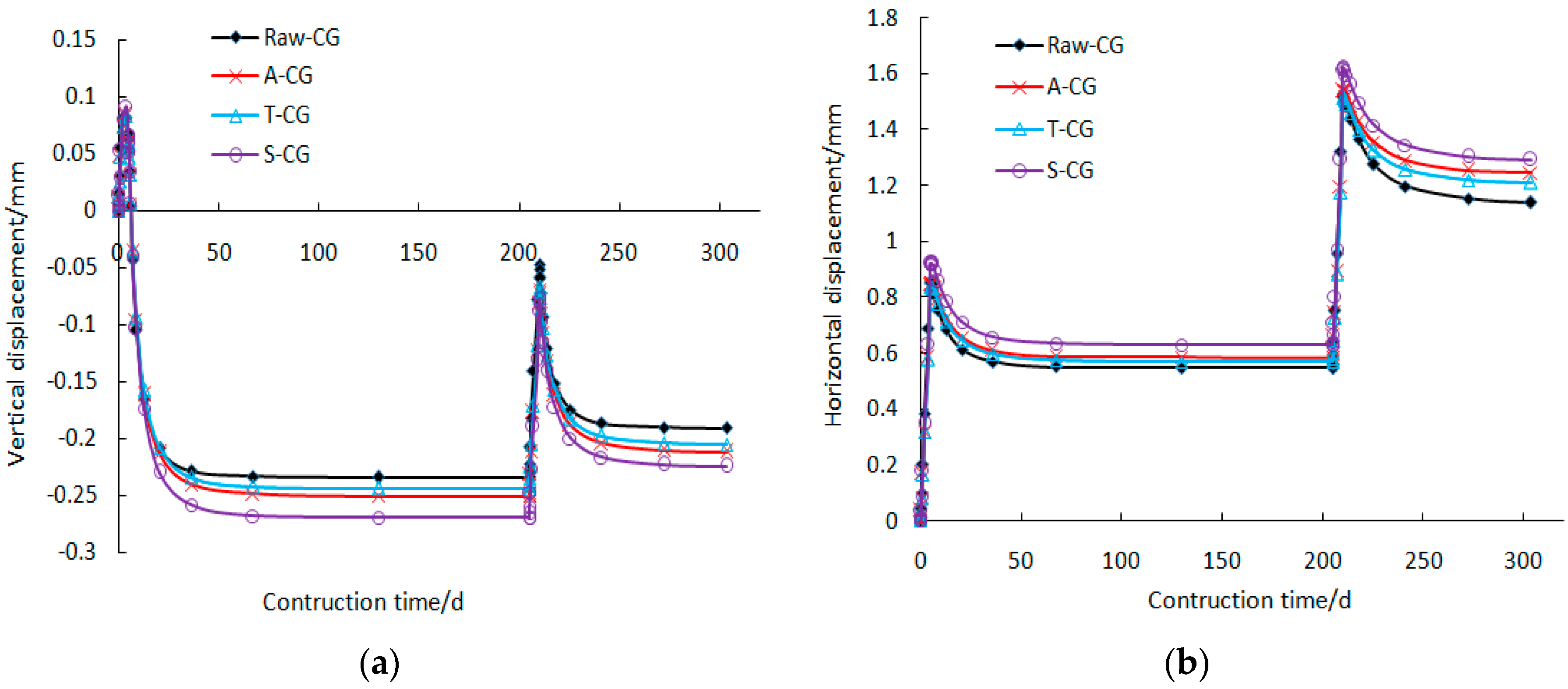
3.3. Displacement of Slope Toe

The change of subgrade slope toe displacement is the macroscopic performance of subgrade stability. In order to further analyze the stability of the filled embankment, the relationship curve of displacement at the slope toe with construction time is shown in Figure 3.
It can be seen from Figure 3 that the displacements of the subgrade slopes filled by four samples are in descending order of S-CG, A-CG, T-CG, and Raw-CG. The maximum horizontal and vertical displacement values of the subgrade slopes filled by S-CG are 1.62 mm and 0.27 mm, respectively, which are less than the standard slope toe displacement rate of not more than 5 mm per day [41]. It indicates that the slope of the embankment slope is stable both horizontally and vertically.

3.4. Factor of Safety

In the view of safety analysis, not only the final stability, but also the stability during the construction period should be considered, so it is necessary to calculate the safety coefficient at each stage. The finite element strength reduction method in PLAXIS software is used to analyze and verify the stability of the coal gangue subgrade. The factor of safety of the four samples in different stages are shown in Table 5.
Table 5 shows that the safety coefficient of the four kinds of coal gangue roadbed are all larger than 1, which proves that the stability of the gangue roadbed is good. The stability of A-CG and S-CG is better than that of Raw-CG during stages 1 to 3, and the stability of S-CG is better than that of Raw-CG in the stage of final consolidation. The other three samples have a similar factor of safety.

3.5. Excess Pore Water Pressure

The total pore water pressure is composed of static pore water pressure and excess pore water pressure which is caused by rapid loading and shearing. Since the short filling time in the simulation can be regarded as the process of rapid lying external load in the soil, the excess pore water pressure is dominated. Excess pore water pressure is the pore water pressure in the soil that exceeds the static water pressure, it occurs with the change of soil load, dissipates with the drainage solidification, so the subgrade stability can be studied through observing the change of super static water pressure [42,43]. The excess pore water pressure changes of each specimen in different stages are shown in Figure 4, and the maximum excess pore water pressure of each stage are shown in Table 6.
As can be seen from Figure 4 and Table 6, during the first phase of construction, the excess pore water pressure is mainly concentrated in the cohesive soil base, and in the order of the value of the excess water pressure of each sample from large to small is S-CG, A-CG, Raw-CG, and T-CG. With the consolidation of the second stage, the pressure distribution spreads to the subgrade, however, the pressure value decreases gradually. In the third stage, with the addition of the second floor of the subgrade, the excess water pressure increases, and the larger pressure value is distributed in the cohesive soil base near the subgrade, and the S-CG specimen pressure value is still the maximum. In the fourth stage, with long-term solidification, the excess water pressure in the Raw-CG specimen is distributed in the lower subgrade and near the clay, and its value is greater than the other three specimens. The above analysis shows that the samples are easier to solidify and stabilize after treatment, the excess water pressure value in the S-CG specimen is the maximum.

4. Microstructure Experiments and Analysis

4.1. SEM and EDS Spectrum

In order to further understand how the material composition, element composition, micromorphology and structure of the coal gangue sample change after soaking in solutions, the sample powders soaked for 15 days were scanned by electron microscopy and determined by EDS. The microstructure spectrum and the elemental patterns of the corresponding points were observed, EDS scanned five points in the corresponding region, and their microscopic morphology and energy spectrum are shown in Figure 5, Figure 6, Figure 7 and Figure 8.
The study of powder samples by SEM illustrates the morphology of the grains in Figure 5, Figure 6, Figure 7 and Figure 8. Many grainy matters of individual clusters and different particle sizes were produced, the gap between particles increased after acidic solution treating, by comparison with Raw-CG. However, the sample particles’ sizes of water treatment are smaller than the untreated coal gangue samples, and the form is relatively loose. The surface of the S-CG grains covered with cotton floc gel, resulting in a dense structure and low porosity [44,45,46,47,48]. After soaked in acetic acid solution, the CG sample contacts with an acid solution to produce a chemical reaction, and the original mineral chemical bonds are broken, decomposed and dispersed, forming more and larger voids. The acid substances escaped from the T-CG sample after being immersed in water, which provided the acidic environment for the CG sample, but their reaction is less intense than being soaked directly in the acid situation. The average contents of each element were obtained by scanning five points in each region, as shown in Table 7.
From the comparative analysis in Table 7, for A-CG and T-CG, a large number of C, Al, Fe, Ca, Mg, K, S and other metal cations escape, the original mineral chemical bond break, decomposition and discrete so that the coal gangue produced gaps, newly formed SiO2 and silicon aluminum compounds are clustered separately. The content of Si in coal gangue after treatment with acid, neutral and alkaline solution increases by 52.2%, 8.8%, and 81.8%, respectively. Therefore, since there is not enough silica gel to supple the lack of bonding material between the particles, more interspaces formed in the A-CG and T-CG. Moreover, the alkali solution is easier to enter the inside of the coal gangue glass body, and OH can break the surface Al-O, Si-O network [46], the Si element of S-CG is 1.8 times that of Raw-CG, and there is Na to provide enough supply for the formation of Na-Si-Al gel wrapped around the coal gangue particles, which agrees well with the SEM results.

4.2. Raman Spectrum

Through the Raman test, the Raman peaks of the samples were obtained. The main types and structural integrity of the material can be judged by the Raman peak, and the half-height width of the Raman peak is used to judge the change of microstructure symmetry of the material. The smaller half-width height of Raman peak, the more regular, the crystal structure and the more consistent the chemical bonds, the performance of the material is more uniform [49]. The Raman spectrogram and the half-height and width charts of the Raman peak (FWHM) are shown in Figure 9 and Figure 10.
As can be seen from Figure 9, the four specimens have two typical carbon materials Raman peaks with D-band between 1356 cm−1 and 1366 cm−1 and G-band from 1591 cm−1 to 1607 cm−1. IG/ID strength ratio of Raw-CG, A-CG, T-CG, S-CG are1.24, 1.20, 1.16, 1.25, respectively, indicating that the sample after being soaked in distilled water and acid solution, the carbon structure in the coal gangue is not complete and has many defects. According to the FWHM information of Raman peaks shown in Figure 10, the D-band and G-band of the acid-alkali treated coal gangue are smaller than those of the untreated coal gangue, indicating that its crystal structure is relatively regular, the chemical bond is consistent, the material tends to be regulated, and the performance is relatively uniform.

4.3. Microstructural Mechanics

In the subgrade simulation, the stability of the coal gangue subgrade is evaluated from three aspects: displacement, safety coefficient, and excess pore water pressure. The microscopic mechanism of the macroscopic effect is analyzed from the microscopic angle.
The displacement of treated coal gangue subgrade is less than that of the untreated coal gangue subgrade. The displacement of A-CG and T-CG is close to each other and smaller than those of S-CG. The slope foot displacement and stability coefficient meet the specification requirements. In terms of excess pore water, after long-term consolidation, the subgrade paved by treated coal gangue samples is more easily consolidated. According to SEM and EDS, A-CG and T-CG particles become smaller and their surface area and internal friction angle increase, which increases their shear strength and compression performance, so they are easy to consolidate. However, the S-CG sample is due to the production of a large amount of Na-Si-Al gel, which increases the cohesion of the sample, improves the density, shear strength and compressive performance, and the consolidation effect is good. Through the Raman test, it can be known that the unstable carbon structure of A-CG and T-CG has been destroyed, resulting in relatively well-structured grains with the crystal structure, which improves the stability of its subgrade. However, S-CG is attached to the surface of coal gangue particles by colloidal coating, which makes the whole material neat and uniform, and ensures the stability of the subgrade. In order to learn the relationship between macro displacement change and micro-influence factors, the final subgrade displacement and Si/Al, IG/ID, D-band FWHM are selected for analysis, and the contrasting diagram is shown in Figure 11.
Figure 11 shows that the increase in Si/Al value in the coal gangue sample, the decrease of IG/ID and D-band FWHM are beneficial to improve the subgrade anti-sinking capacity. In summary, the stability of the coal gangue subgrade can be improved by washing the coal gangue or using alkali solution to stimulate the activity of the coal gangue to produce gel substances.

5. Conclusions

The displacement of the coal gangue subgrade is obtained by PLAXIS numerical simulation method. The influence of different acidity solutions on the displacement of the coal gangue subgrade is analyzed via SEM, EDS and Raman spectra from the view of microscopic. The main conclusions are obtained from the follows:
(1) The displacement settlement of the coal gangue subgrade is gradually reduced from the top of the roadbed to the underside of the clay. The larger displacement is concentrated in the area from the surface of the subgrade to 4.0 m below the surface of the subgrade. After the long-term consolidation, the displacement of the coal gangue subgrade meets the requirements of subgrade design specifications. Its order from large to small is Raw-CG, S-CG, T-CG, A-CG.
(2) The slope foot displacement, the boundary interface shear stress and the safety coefficient value all meet the specification requirements. During the construction of the subgrade, the maximum pressure of excess pore water is gradually moved from the clay below the subgrade to the bottom of the subgrade. Over time, the pore water pressure gradually decreases and eventually reaches stability. A-CG sample solidification is the best, T-CG medium, S-CG least, but they are all better than untreated coal gangue samples in terms of long-term consolidation.
(3) A-CG and T-CG have small grain, enlarged surface area, and internal friction angle, unstable carbon structure destruction, material regulation, and uniform performance, thus improving the shear strength, pressure strength and solidification effect of the subgrade. However, after alkali treatment of coal gangue, Na-Si-Al gel is generated, which increases the density, viscosity and shear strength of the gangue. Its material overall regulation, uniform performance, thus ensuring the stability of the subgrade and good solidification.
(4) The activity of coal gangue is treated by acid, neutral solution or stimulated alkali, increases the Si/Al of coal gangue, reduces IG/ID and D-band FWHM, and forms gel substances, which can improve the stability of the subgrade.

Author Contributions

Conceptualization, X.Y. and Y.Z.; Experiments, X.Y.; Data Curation, X.Y. and Y.Z.; Writing—Original Draft Preparation, Y.Z.; Writing—Review and Editing, Y.Z. and Z.L. All authors have read and agreed to the published version of the manuscript.

Funding

This research was funded by the National Natural Science Foundation of China, grant number 51669025 and China Scholarship Council.

Conflicts of Interest

The authors declare no conflict of interest.

References

  1. Tang, Z.; Li, W.; Ke, G.; Zhou, J.; Tam, V. Sulfate attack resistance of sustainable concrete incorporating various industrial solid wastes. J. Clean. Prod. 2019, 218, 810–822. [Google Scholar] [CrossRef]
  2. Humsa, T.; Srivastava, R. Impact of rare earth mining and processing on soil and water environment at Chavara, Kollam, Kerala: A case study. Prog. Earth Planet. Sci. 2015, 11, 566–581. [Google Scholar] [CrossRef] [Green Version]
  3. Jiang, L.; Liang, B.; Xue, Q.; Yin, C. Characterization of phosphorus leaching from phosphate waste rock in the Xiangxi River watershed, Three Gorges Reservoir, China. Chemosphere 2016, 150, 130–138. [Google Scholar] [CrossRef] [PubMed]
  4. Zhang, J.; Sun, C.; Dong, H.; Cao, Y.; Zhou, S.; Guo, Z.; Fan, W. Exploration of comprehensive utilization of coal gangue resource in Daqing Mountain. Multipurp. Util. Miner. Resour. 2017, 2, 8–11. [Google Scholar] [CrossRef]
  5. Xia, B.; Wang, X.; Zhang, Y. Synthesis of zeolite adsorbents by coal gangue in Erdos. Bull. Chin. Ceram. Soc. 2018, 37, 1462–1466. [Google Scholar]
  6. Yao, Y.; Li, Y.; Liu, X.; Jiang, S.; Feng, C.; Rafanan, E. Characterization on a cementitious material composed of red mud and coal industry byproducts. Constr. Build. Mater. 2013, 47, 496–501. [Google Scholar] [CrossRef]
  7. Salguero, F.; Grande, J.; Valente, T.; Garrido, R.; Torre, M.; Fortes, J.; Sanchez, A. Recycling of manganese gangue materials from waste–dumps in the Iberian pyrite belt-application as filler for concrete production. Constr. Build. Mater. 2014, 54, 363–368. [Google Scholar] [CrossRef]
  8. Amir, M.; Morteza, R. Application of coal waste powder as filler in hot mix asphalt. Constr. Build. Mater. 2014, 66, 476–483. [Google Scholar] [CrossRef]
  9. Duan, X.; Xia, J.; Yang, J. Influence of coal gangue fine aggregate on microstructure of cement mortar and its action mechanism. J. Build. Mater. 2014, 17, 700–705. [Google Scholar] [CrossRef]
  10. Dong, Z.; Xia, J.; Fan, C.; Cao, J. Activity of calcined coal gangue fine aggregate and its effect on the mechanical behavior of cement mortar. Constr. Build. Mater. 2015, 100, 63–69. [Google Scholar] [CrossRef] [Green Version]
  11. Wang, C.; Ni, W.; Zhang, S.; Wang, S.; Gai, G.; Wang, W. Preparation and properties of autoclaved aerated concrete using coal gangue and iron ore tailings. Constr. Build. Mater. 2016, 104, 109–115. [Google Scholar] [CrossRef]
  12. Zhang, H.; Zhao, Y. A study on anti-cracking performance of lime and fly–ash stabilized coal gangue roadbase materials. Appl. Mech. Mater. 2014, 638–640, 1113–1116. [Google Scholar] [CrossRef]
  13. Liu, X.; Tang, B.; Yin, H.; Emile, M. Durability and environmental performance of bayer red mud–coal gangue–based road base material. Chin. J. Eng. 2018, 40, 438–445. [Google Scholar] [CrossRef]
  14. Yang, Q.; Lü, M.; Luo, Y. Effects of surface-activated coal gangue aggregates on properties of cement–based materials. J. Wuhan Univ. Technol. (Mater. Sci. Ed.) 2013, 28, 1118–1121. [Google Scholar] [CrossRef]
  15. Zhang, N.; Liu, X.; Sun, H. Hydration characteristics of intermediate-calcium based cementitious materials from red mud and coal gangue. Chin. J. Mat. Res. 2014, 28, 325–332. [Google Scholar] [CrossRef]
  16. Yang, X.; Xiong, R.; Yang, F.; Yin, H.; Yang, T. Laboratory investigation of the high temperature rheological property of activated coal gangue modified asphalt binder. Appl. Mech. Mater. 2015, 744–746, 1261–1265. [Google Scholar] [CrossRef]
  17. Lin, H.; Li, G.; Dong, Y.; Li, J. Effect of pH on the release of heavy metals from stone coal waste rocks. Int. J. Miner. Process. 2017, 165, 1–7. [Google Scholar] [CrossRef]
  18. Peng, B.; Li, X.; Zhao, W.; Yang, L. Study on the release characteristics of chlorine in coal gangue under leaching conditions of different pH values. Fuel 2018, 217, 427–433. [Google Scholar] [CrossRef]
  19. Xue, Q.; Lu, H.; Zhao, Y.; Liu, L. The metal ions release and microstructure of coal gangue corroded by acid-based chemical solution. Environ. Earth Sci. 2014, 71, 3235–3244. [Google Scholar] [CrossRef]
  20. Ma, H.; Yi, C.; Chen, H.; Shi, J. Property and cementation mechanism of alkali–activated coal gangue–slag cementitious materials. Chin. J. Mater. Res. 2018, 32, 898–904. [Google Scholar] [CrossRef]
  21. Dong, L.; Liang, X.; Song, Q.; Gao, G.; Song, L.; Shu, Y.; Shu, X. Study on Al2O3 extraction from activated coal gangue under different calcination atmospheres. J. Therm. Sci. 2017, 26, 570–576. [Google Scholar] [CrossRef]
  22. Luo, J.; Li, G.; Jiang, T.; Peng, Z.; Rao, M.; Zhang, Y. Conversion of coal gangue into alumina, tobermorite and TiO2–rich material. J. Cent. South Univ. 2016, 23, 1883–1889. [Google Scholar] [CrossRef]
  23. Zhang, C. Coal Gangue Resource Recycling Technology; Chemical Industry Press: Beijing, China, 2017. [Google Scholar]
  24. Shi, C.; Sha, A.; Yan, Q.; Tan, Y.; Han, J. Research and Application for Road Construction Technology of Coal Gangue; China Communications Press Co., Ltd.: Beijing, China, 2016. [Google Scholar]
  25. Zhang, J.; Li, M.; Taheri, A.; Zhang, W.; Wu, Z.; Song, W. Properties and application of backfill materials in coal mines in China. Minerals 2019, 9, 53. [Google Scholar] [CrossRef] [Green Version]
  26. Li, J.; Huang, Y.; Chen, Z.; Li, M.; Qiao, M.; Kizil, M. Particle-crushing characteristics and acoustic-emission patterns of crushing gangue backfilling materials under cyclic loading. Minerals 2018, 8, 244. [Google Scholar] [CrossRef] [Green Version]
  27. Chaiyaput, S.; Bergado, D.; Artidteang, S. Measured and simulated results of a kenaf limited life geosynthetics (LLGs) reinforced test embankment on soft clay. Geotext. Geomembr. 2014, 42, 39–47. [Google Scholar] [CrossRef]
  28. Rowe, R.; Taechakumthorn, C. Design of reinforced embankments on soft clay deposits considering the viscosity of both foundation and reinforcement. Geotext. Geomembr. 2011, 29, 448–461. [Google Scholar] [CrossRef]
  29. Benmebarek, S.; Berrabah, F.; Benmebarek, N. Effect of geosynthetic reinforced embankment on locally weak zones by numerical approach. Comput. Geotech. 2015, 65, 115–125. [Google Scholar] [CrossRef]
  30. Horpibulsuk, S.; Chinkulkijniwat, A.; Cholphatsorn, A.; Suebsuk, J.; Liu, M. Consolidation behavior of soil–cement column improved ground. Comput. Geotech. 2012, 43, 37–50. [Google Scholar] [CrossRef] [Green Version]
  31. Sun, K.; Peng, L.; Du, Y.; Tang, Q.; Yang, G. Coal gangue embankment settlement and stress analysis based on FLAC3D and comparative study with field test results. Highw. Eng. 2014, 39, 83–87. [Google Scholar] [CrossRef]
  32. Bergado, D.; Voottipruex, P.; Tanchaisawat, T. 2D and 3D simulation of geogrid-reinforced geocomposite material embankment on soft Bangkok clay. Geosynth. Int. 2009, 16, 420–432. [Google Scholar] [CrossRef]
  33. Gündüz, B. Analysis of Settlements of Test Embankments during 50 Years–A Comparison between Field Measurements and Numerical Analysis. Master’s Thesis, Lund University, Lund, Sweden, 2008. [Google Scholar]
  34. ASTM E1621-13. Standard Guide for Elemental Analysis by Wavelength Dispersive X-Ray Fluorescence Spectrometry; ASTM International: West Conshohocken, PA, USA, 2013. [Google Scholar]
  35. Zhang, Y.; Meng, F.; Guo, L.; Zhang, X.; Li, Z. Influence of weathering property of coal gangue on highway performance. Coal Eng. 2011, 12, 94–96. [Google Scholar]
  36. Zheng, L. Analysis of leaching test of coal gangue. Opencast Min. Technol. 2008, 4, 51–52. [Google Scholar] [CrossRef]
  37. Yang, X. Effect of Static Leaching on Coal Gangue Subgrade Settlement. Master’s Thesis, Inner Mongolia Agricultural University, Hohhot, China, 2014. [Google Scholar]
  38. Ministry of Transport of the People’s Republic of China. Test Methods of Aggregate for Highway Engineering (JTG E42—2005); China Communication Publishing & Media Management Co., Ltd.: Beijing, China, 2005.
  39. Cai, L.; Wang, P. Analysis on settlement of high water level subgrade based on PLAXIS. Subgrade Eng. 2017, 6. [Google Scholar] [CrossRef]
  40. CCCC Highway Co. Ltd. Code for Design of Ground Base and Foundation of Highway Bridges and Culverts (JTG D63-2007); China Communications Press: Beijing, China, 2007. [Google Scholar]
  41. CCCC Second Highway Co. Ltd. Specifications for Design of Highway Subgrades (JTG D30-2015); China Communications Press: Beijing, China, 2015. [Google Scholar]
  42. Sun, Y.; Song, E. Dynamic simulation of “12·20” Shenzhen landslide. Chin. J. Geotech. Eng. 2018, 40, 441–448. [Google Scholar] [CrossRef]
  43. Li, Q.; Wu, Z.; Zhang, D. Soil compaction effect of bagged grouting piles in saturated soft clay subgrade. J. Southwest JiaoTong Univ. 2018, 53, 1026–1032, 1047. [Google Scholar] [CrossRef]
  44. Zhang, N.; Sun, H.; Liu, X.; Zhang, J. Early-age characteristics of red mud-coal gangue cementitious material. J. Hazard. Mater. 2009, 167, 927–932. [Google Scholar] [CrossRef]
  45. Zhang, N.; Liu, X.; Sun, H.; Li, L. Evaluation of blends bauxite-calcination-method red mud with other industrial wastes as a cementitious material: Properties and hydration characteristics. J. Hazard. Mater. 2011, 185, 329–335. [Google Scholar] [CrossRef]
  46. Liu, X.; Zhang, N.; Yao, Y.; Sun, H.; Feng, H. Micro-structural characterization of the hydration products of bauxite-calcination-method red mud-coal gangue based cementitious materials. J. Hazard. Mater. 2013, 262, 428–438. [Google Scholar] [CrossRef]
  47. Zhang, N.; Li, H.; Liu, X. Hydration mechanism and leaching behavior of bauxite-calcination-method red mud-coal gangue based cementitious materials. J. Hazard. Mater. 2016, 314, 172–180. [Google Scholar] [CrossRef]
  48. Zhang, C.; Xue, J.; Fang, L. Mechanical properties and microstructures of alkali activated burned coal gangue cementitious material. J. Chin. Ceram. Soc. 2004, 32, 1276–1280. [Google Scholar] [CrossRef]
  49. Feng, Y.; Shen, Y.; You, Y. Raman spectra testing of residual stress in the carbon fiber reinforced composites. Nondestruct. Test. 2019, 41, 20–23. [Google Scholar] [CrossRef]
Figure 1. Model of coal gangue subgrade.
Minerals 10 00218 g001
Figure 2. Displacement cloud model.
Minerals 10 00218 g002
Figure 3. Curve of slope toe. (a) Vertical displacement, (b) Horizontal displacement.
Minerals 10 00218 g003
Figure 4. Pore water pressure cloud model.
Minerals 10 00218 g004
Figure 5. SEM and EDS spectrum of Raw-CG. (a) SEM Spectrum of Raw-CG; (b) EDS Spectrum of Raw-CG. Spots Spectrum: scanning spots of EDS.
Minerals 10 00218 g005
Figure 6. SEM and EDS spectrum of A-CG. (a) SEM Spectrum of A-CG; (b) EDS Spectrum of A-CG.
Minerals 10 00218 g006
Figure 7. SEM and EDS spectrum of T-CG. (a) SEM Spectrum of T-CG; (b) EDS Spectrum of T-CG.
Minerals 10 00218 g007
Figure 8. SEM and EDS spectrum of S-CG. (a) SEM Spectrum of S-CG; (b) EDS Spectrum of S-CG.
Minerals 10 00218 g008
Figure 9. Raman spectrum of coal gangue sample.
Minerals 10 00218 g009
Figure 10. The half-height and width charts of the Raman peak (FWHM) of coal gangue.
Minerals 10 00218 g010
Figure 11. Comparison of final displacement and micro-influence factors.
Minerals 10 00218 g011
Table 1. Components of coal gangue /%.
CompositionSiO2Al2O3Fe2O3CaOMgOSO3K2OP2O5Na2OTiO2
Content45.832.84.51.17.70.64.10.21.22.0
Table 2. Material parameters used in the PLAXIS.
SampleUnsaturated Weight/kN·m−3E0/MPaνφ/°c/MPaψ/°
Raw-CG16.873.10.3030.315.10
A-CG17.0158.30.3032.020.80
T-CG16.7142.50.3030.49.70
S-CG18.4146.20.3012.171.30
Clay layer18.080.00.3320.020.00
Table 3. Maximum vertical displacement /mm.
SampleStage 1Stage 2Stage 3Stage 4
Raw-CG−2.68−3.46−7.05−8.60
A-CG−2.28−3.08−5.85−7.06
T-CG−2.28−3.07−5.88−7.10
S-CG−2.50−3.37−6.35−7.69
Table 4. Maximum shear stress at different stages/kN·m−2.
SampleA InterfaceB Interface
Stage 3Stage 4Stage 1Stage 2Stage 3Stage 4
Raw-CG3.665.594.505.228.858.74
A-CG3.846.394.195.1812.0710.18
T-CG3.746.164.065.1011.519.53
S-CG4.427.104.495.6212.2710.13
Table 5. Coefficient in different stages of coal gangue subgrade.
SampleStage 1Stage 2Stage 3Stage 4
Raw-CG3.9174.1042.5522.363
A-CG5.1835.4783.5962.181
T-CG3.8653.9932.4082.151
S-CG4.4034.6562.8293.105
Table 6. Maximum excess pore water pressure /kN m−2.
SampleStage 1Stage 2Stage 3Stage 4
Raw-CG−26.66−3.00 × 10⁻³−33.50−496.19 × 10⁻³
A-CG−27.05−2.95 × 10⁻³−32.88−330.75 × 10⁻³
T-CG−26.54−3.02 × 10⁻³−32.45−361.84 × 10⁻³
S-CG−29.25−3.53 × 10⁻³−35.72−385.17 × 10⁻³
Table 7. Average value of element relative content in five scanning points of CG samples /%.
SampleSiAlFeCaMgKSCONaOthers
Raw-CG15.912.03.00.21.31.50.327.438.2-0.2
A-CG24.210.02.8-1.00.40.111.250.2-0.1
T-CG17.39.72.30.11.10.60.29.559.1-0.1
S-CG28.93.81.00.10.50.3-8.056.90.40.1

