Article

New Candidate Ultralow-Velocity Zone Locations from Highly Anomalous SPdKS Waveforms

1
Department of Geology and Geophysics, University of Utah, Salt Lake City, UT 84112-0102, USA
2
Department of Earth Sciences, University of Oxford, Oxford OX1 3AN, UK
3
Department of Earth & Planetary Sciences, Johns Hopkins University, Homewood Campus, Baltimore, MD 21218, USA
*
Author to whom correspondence should be addressed.
Minerals 2020, 10(3), 211; https://doi.org/10.3390/min10030211
Submission received: 25 January 2020 / Revised: 21 February 2020 / Accepted: 24 February 2020 / Published: 26 February 2020

Abstract

:
Ultralow-velocity zones (ULVZs) at the core–mantle boundary (CMB) represent some of the most preternatural features in Earth’s mantle. These zones most likely contain partial melt, extremely high iron content ferropericlase, or combinations of both. We analyzed a new collection of 58,155 carefully processed and quality-controlled broadband recordings of the seismic phase SPdKS in the epicentral distance range from 106° to 115°. These data sample 56.9% of the CMB by surface area. From these recordings we searched for the most anomalous seismic waveforms that are indicative of ULVZ presence. We used a Bayesian approach to identify the regions of the CMB that have the highest probability of containing ULVZs, thereby identifying sixteen regions of interest. Of these regions, we corroborate well-known ULVZ existence beneath the South China Sea, southwest Pacific, the Samoa hotspot, the southwestern US/northern Mexico, and Iceland. We find good evidence for new ULVZs beneath North Africa, East Asia, and north of Papua New Guinea. We provide further evidence for ULVZs in regions where some evidence has been hinted at before beneath the Philippine Sea, the Pacific Northwest, and the Amazon Basin. Additional evidence is shown for potential ULVZs at the base of the Caroline, San Felix and Galapagos hotspots.

1. Introduction

Ultralow-velocity zones (ULVZs), first detected in the early 1990s [1,2], are thin zones of ultra-reduced seismic wave speeds sitting directly on top of the core–mantle boundary (CMB). Observations of ULVZs have been made with a wide variety of seismic probes [3] and have revealed that these zones may exhibit reductions in S-wave velocity as large as 50% [4]. The first postulated explanation for these features was a layer of partial melt [4,5,6,7], which has remained a popular explanation through the ensuing decades [8,9,10,11,12]. Although partial melt has remained a favorable candidate to explain ULVZ existence, it is not yet certain what gives rise to the seismic waveforms used to infer their presence. Other candidate scenarios, such as purely compositional differences on top of [13,14,15,16] or even below the CMB [17], are also likely possibilities. It is also possible that all things we collectively refer to as ULVZs are not manifestations of just one of these scenarios. Nonetheless, determination of where and what these ULVZ features are can provide important insights into the dynamics, composition, evolution, and formation of the Earth.
Although it has been nearly three decades since the discovery of ULVZs we still know relatively little about them. First, we know little about where they do and do not exist. According to a recent review paper by Yu and Garnero [3], less than 20% of the CMB has been explored for ULVZ presence. This has not dissuaded researchers from making correlations between ULVZ presence and other observables, such as the surface location of hotspot volcanoes [18] or the edges of Large Low Velocity Provinces (LLVPs) [3]. Indeed, some large ULVZs have been detected lying directly beneath hotspot volcanoes [5,19,20,21,22] and near the edges of LLVPs [10,23,24,25,26]. However, given that such a small area of the CMB has been explored and that, recently, large ULVZs have also been detected near the edges of possible subducted slab material [27], such correlations may be premature.
Second, we know relatively little about the elastic properties of ULVZs. Reports of P- and S-wave velocity reductions (δVP and δVS) inside ULVZs vary widely from δVP = 0% to −25% and δVS = −2% to −50% [3,28]. In part, this wide range of reported velocity reductions may be due to the non-uniqueness of ULVZ models that may explain a given set of seismic waveforms [29]. Most studies typically provide a solution for a best-fit or preferred ULVZ model, with little attention devoted to the other models that fit their observations equally well. It is also likely that not everything reported as a ULVZ is the same thing, and perhaps features such as partially molten ULVZs, compositional ULVZs and core rigidity zones (CRZs) all exist and manifest different elastic properties. To complicate matters even more, several of these features may even be co-located, such as ULVZs overlying CRZs.
ULVZs were first identified using the SPdKS seismic phase [1,2] which we utilize in this paper. SPdKS starts off as a down-going S-wave that strikes the CMB at the critical angle for P-wave core-diffraction generating legs of Pdiff (Pd) along the CMB near the source-side of the ray path. This Pd energy enters the core as a P-wave and converts back to an S-wave as it exits the core. The ray path for SPdKS is shown in Figure 1a. A complimentary phase SKPdS also exists (Figure 1b), in which the Pd segment of the ray occurs on the receiver-side of the path. In a 1-D Earth model, SPdKS and SKPdS arrive at a receiver at the same time and are indistinguishable from one another. In addition, an infinite number of SPdKS + SKPdS combinations also exist where the arrival has some amount of Pd energy on both the source- and receiver-sides of the ray path. In general, the term SPdKS is used to describe all these possible paths. Typically, SPdKS is referenced to the SKS arrival. As SPdKS primarily varies from the SKS ray path along the Pd segments on the CMB, we attribute abnormalities in the SPdKS timing or waveform characteristics as having occurred along the Pd-segment of the path. In order to represent this in map view we draw the location of the Pd-segments of the maximum Pd length on the source- and receiver-sides. For example, Figure 1c shows an example for a single event. Here, we have projected the maximum length Pd leg of SPdKS onto the CMB in blue. Similarly, we have projected the maximum length Pd leg of SKPdS onto the CMB with the orange lines. We assume that abnormalities in any of the individual recordings occur in the immediate vicinity of either of these Pd segments, but it may not be possible to distinguish from which side of the path (source- vs. receiver-side) a particular anomaly originates from a single seismic recording.
Highly anomalous SPdKS arrivals have been observed and linked to ULVZ presence in several previous studies [20,27,30,31]. Key features of these anomalous waveforms are the presence of more seismic arrivals than predicted from the Preliminary Reference Earth Model (PREM) [32] and an apparent SPdKS amplitude that is larger than the SKS arrival. An example of what anomalous types of waveforms may look like is presented in Figure 2. Figure 2a shows synthetic predictions for the PREM model. The synthetics are aligned in time to the onset of the SKS arrival. In these synthetics, we observe a single SKS arrival at a distance of 100°. Theoretically, the SPdKS phase first arrives at a distance near 104°. However, as SPdKS arrives nearly coincidentally with SKS, it is not distinguishable as a separate arrival. At 111°, we observe the broadening of the SKS arrival as the delay between SPdKS and SKS increases. At roughly 112° we see the emergence of SPdKS as distinct from SKS. As SPdKS emerges from the shoulder of SKS, it has a lower amplitude than SKS. Figure 2b shows synthetic seismograms for a model with a ULVZ placed in the path of SPdKS. Here, we highlight in red specific waveforms that we can readily identify as anomalous. First note that two distinct arrivals are present, whereas the PREM model only predicted a single arrival. Second, the second arrival has an amplitude on par with or greater than the amplitude of the SKS arrival. In this paper, we specifically search for such anomalous arrivals. Previous work has suggested that these kinds of arrivals can be found in the distance range from 106° to 115° [20,27], so we focus our search in this distance range, which is highlighted in Figure 2.
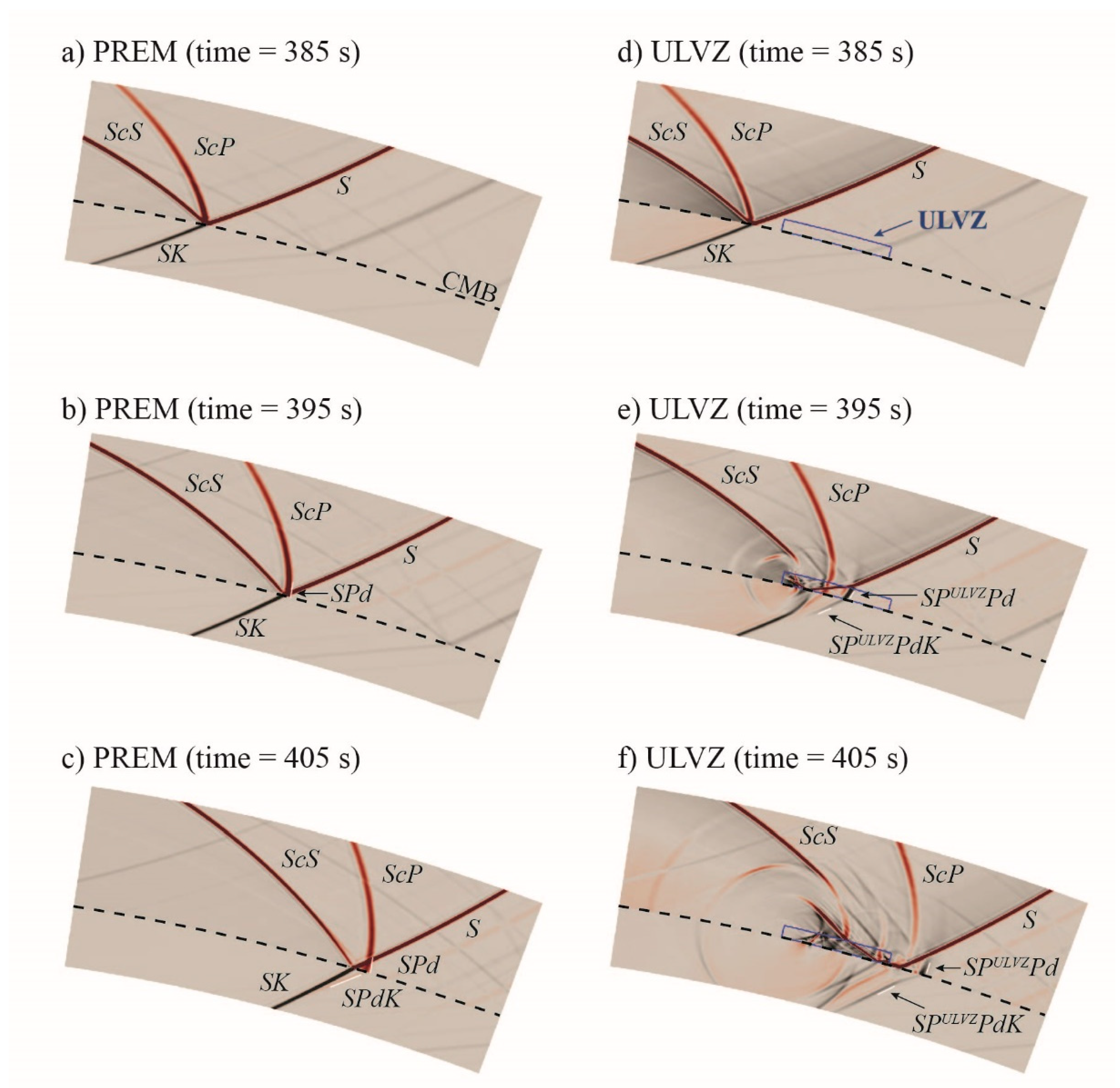
One way in which a ULVZ can generate such anomalous recordings is demonstrated in Figure 3. This figure shows snapshots of the displacement seismic wavefield at the CMB for both the PREM model and the same ULVZ model, as shown in Figure 2. Here, the seismic wavefield is computed with a dominant period of approximately 1 s using the AxiSEM3D technique [33,34]. Animations of these wavefield simulations are included as online supplements (Videos S1 and S2). Three snapshots for the PREM model are displayed along the left-hand column. In the first snapshot (Figure 3a,d) we can see S, ScS, ScP and the SK leg of SKS are identical for both the PREM and ULVZ model. In the PREM wavefield, we see the Pd portion of SPdKS first start to emerge at a time of roughly 395 s (Figure 3b), and by 405 s (Figure 3c) it is well developed and separated from the rest of the wavefield. Here, we can see the down-going energy exit into the core (SPdK). In the ULVZ model at 395 s (Figure 3e), we see that the down-going S-wave has interacted with the ULVZ. As the S-wave strikes the ULVZ, a converted P-wave is created (SPULVZ). This converted phase diffracts and by 405 s (Figure 3f) we can see the development of the associated Pd phase entering the core (SPULVZPdK). As the converted P-wave at the ULVZ travels faster than an S-wave in PREM, this new arrival, SPULVZPdKS, arrives earlier than SPdKS in the PREM model and shows up as an anomalous arrival (as in Figure 2b). This may not be the only means by which an anomalous arrival such as we observe gets generated, but this demonstrates one way by which a simple ULVZ model can produce such waveforms.
ULVZs are not necessarily the only structural feature that could explain anomalous SPdKS waveforms. Garnero and Jeanloz [35] showed that synthetic seismograms computed for a gradational boundary between the core and mantle may be quite similar to synthetics computed for some ULVZ models. This scenario is referred to as a core–mantle transition zone (CMTZ). Another scenario is referred to as a core rigidity zone (CRZ) [17]. In this scenario, light sediments collect on the underside of the mantle preferentially in topographic highs. Little attention has been paid to either of these scenarios in most ULVZ studies. One study has inferred the presence of possible CRZ material [36], and no studies have specifically singled out a CMTZ origin to anomalous waveforms; rather, the vast majority of studies have focused on ULVZ interpretations. As discussed in the previous paragraph, for the highly anomalous types of waveforms we present here, a simple ULVZ model seems adequate to explain the observations. However, previous work has demonstrated that anomalous waveforms as we discuss in this paper can be synthesized using a CRZ model [17]. CMTZ models have been largely untested and we do not know if these types of models can also produce such anomalies. In this paper, we refer to all features giving rise to anomalous waveforms as ULVZs, emphasizing that other explanations cannot currently be ruled out.
In this paper, we make no attempt to provide further constraints on ULVZ elastic parameters. Rather, we focus on locating some of the potentially most anomalous ULVZ regions. Here, we search for anomalies in the seismic phase SPdKS. We collect a new global data set of SPdKS waveforms focusing on recordings in the epicentral distance range from 106° to 115°. The most recent global survey of SPdKS waveforms was published in 2004 [37]. In that paper, data from 53 events were used with a total of 443 seismograms in the distance range from 105° to 125°. As discussed above, the anomalous waveforms we search for occur in a limited epicentral distance range. In this paper we were able to use recordings from over 1000 events and a total of 58,155 unique seismograms in the distance range 106° to 115°. We have obtained coverage of the CMB of approximately 50%. We implement a Bayesian inversion of these anomalous waveforms to invert for regions of the Earth’s CMB where ULVZ-like features most likely exist. The Bayesian approach combines prior knowledge with the data information to provide answers expressed in terms of the posterior probability density of unknown anomalous regions. These regions may contain partial melt; however, we are not able to constrain that scenario at this time. If partial melt does exist at the CMB, these would be the locations to search.

2. Materials and Methods

2.1. Seismic Data

We collected broadband seismic recordings from earthquakes occurring from 1990 through 2017. We collected data for all events with magnitudes MW ≥ 5.8, depths ≥ 75 km, and within the epicentral distance range: 90° ≤ Δ ≤ 130°. Data were collected from the Incorporated Research Institutions for Seismology (IRIS), the Caltech/USGS Southern California Earthquake Data Center (SCEDC), the Canadian National Seismograph Network (CNSN) [38], and the Observatories & Research Facilities for European Seismology (ORFEUS).
Data are initially processed as follows: (1) the mean and trend of the trace is removed, (2) instrument response is removed, (3) files are rotated to the great circle path and the radial component of the trace is retained, (4) traces with data gaps within ±200 s of the SKS arrival were removed, (5) seismograms retrieved from more than one data center were reduced such that only a single instance of a seismogram was retained. In order to assess data quality, we first constructed a two-layer neural network similar to that of Valentine and Woodhouse [39]. We classified 60,000 seismic traces by hand as either being high- or low-quality. Then, we trained five independent networks on 10,000 seismograms each, where the seismograms were drawn randomly but not repeating for each neural network. We compared the neural networks to the remaining 10,000 seismograms that were classified but not used in training the network. The networks each demonstrated roughly 90% agreement with our initial picks. We calculated a data quality score for all seismograms in our collection by taking the average score of the five neural networks. Next, we went through all seismograms, one event at a time, and manually inspected each trace, removing or reinserting traces that the neural network misclassified. The initial classification by the neural network significantly reduced the amount of time required to quality control the traces. All traces were classified as either high- or low-quality, yet we retained all traces for possible later re-analysis and for future efforts to improve artificial intelligence algorithms for data selection. The final data processing step was to resample all traces to the same sample rate (40 Hz) and unify the start time of all traces from the different data sources.
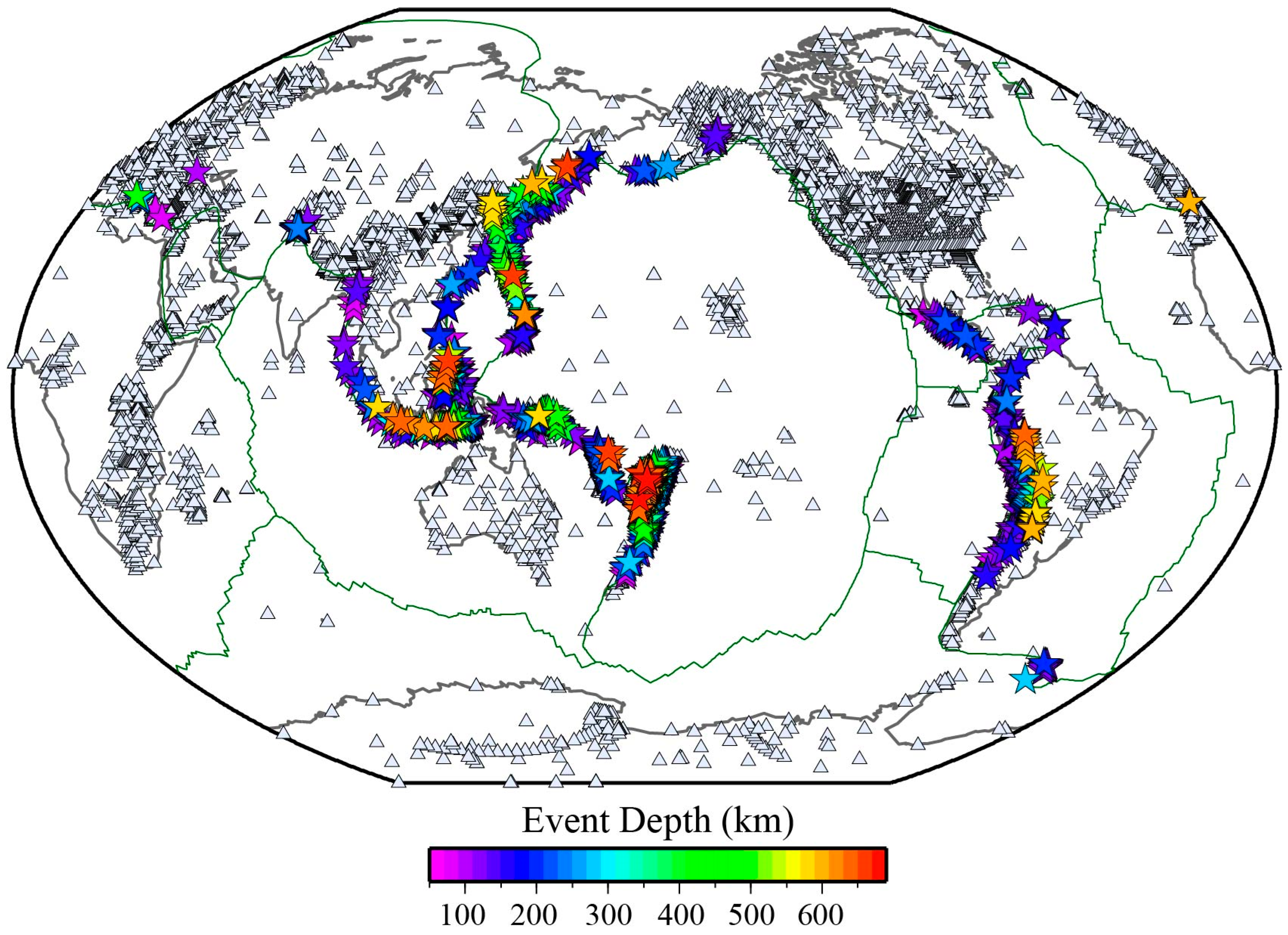
Once data were examined for quality, we created an empirical SKS wavelet. This was done similarly to Thorne and Garnero [37], in which SKS records in the distance range from 90° to 105° were aligned by multi-channel cross-correlation [40] and stacked to generate an average SKS waveform for the event. Each event was examined to ensure that this empirical SKS arrival was uncomplicated and impulsive. Events with complicated SKS wavelets were discarded. In addition, events with no records in the distance range between 105° and 130° were also discarded, as these events didn’t contain SPdKS energy. In total, we retained data for 1146 events (Figure 4).
From these events we collected a total of 606,770 seismograms in the distance range 90° to 130°. Of these records, we classified 271,602 (44.8%) as high quality. The useable traces consisted of 111,398 records in the distance range 105° to 130° where SPdKS may be observed, and 58,155 records in the distance range 106° to 115° that we focus on in this paper. The final data set of high-quality traces consisted of recordings from 13,156 unique broadband sensors (Figure 4).
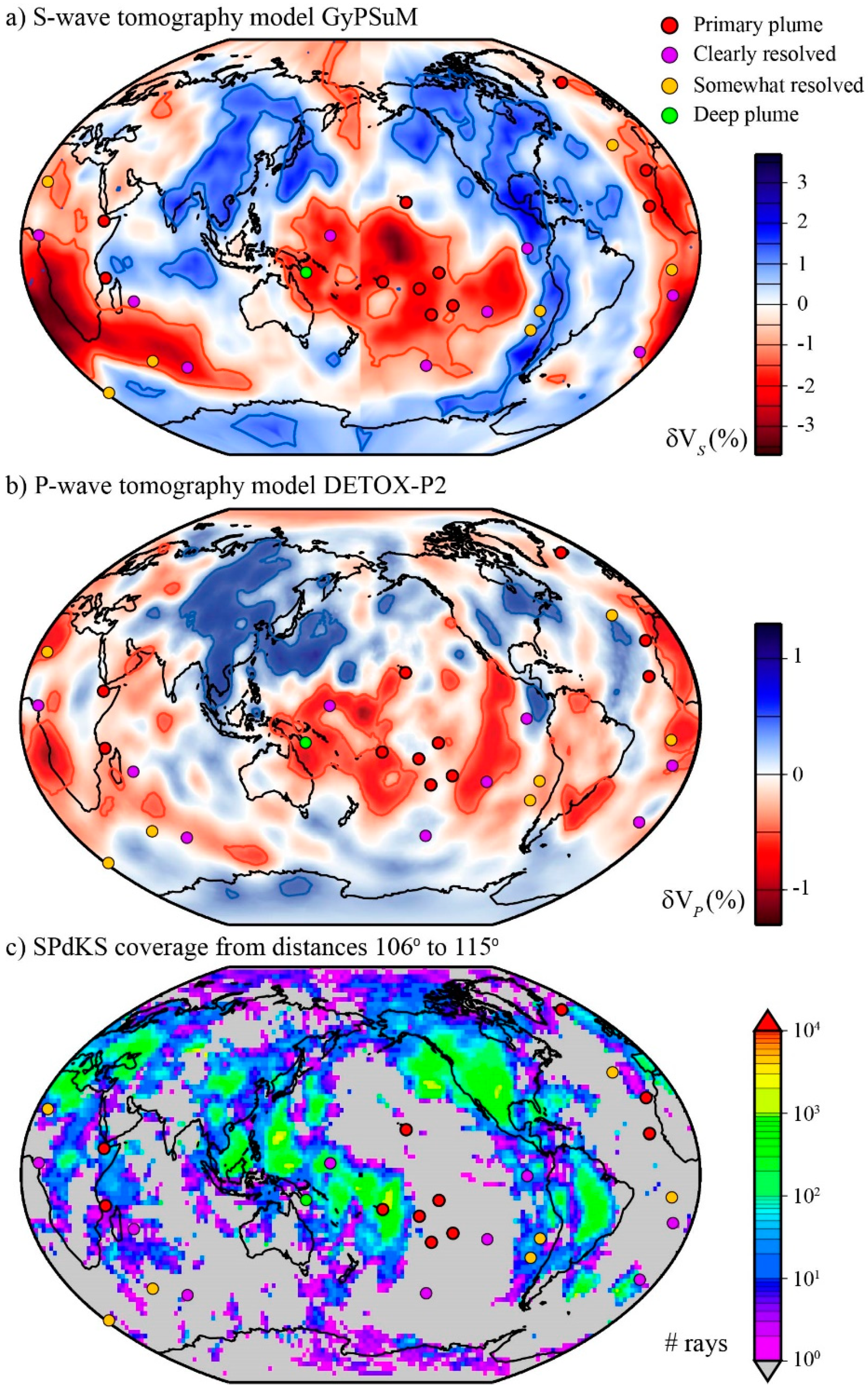
In this paper, we focus on recordings in the distance range from 106° to 130°. In order to quantify the data coverage for this subset of data, we projected the Pd segments of SPdKS and SKPdS on to the CMB and counted the number of Pd segments crossing within a 2° × 2° grid space. The resulting data coverage is shown in Figure 5 and consists of coverage of 56.9% of the CMB by surface area. As noted in the introduction, ULVZ locations have been linked to the base of whole mantle plumes giving rise to hotspots, the edges of LLVPs, and the edges of subducted slab remnant. In Figure 5, we have included the locations of plumes conduits that may extend to the CMB, as resolved by French and Romanowicz [41]. Of these possibly deep-seated plumes, our data coverage is best beneath the Afar, Cameroon, Canary, Cape Verde, Caroline, Comores, Galapagos, Hoggar, Iceland, Juan Fernandez, Reunion, Samoa, San Felix, and Tristan hotspots. Figure 5 also shows the lowermost mantle slice of S-wave tomography model GyPSum [42] and P-wave tomography model DETOX-P2 [43]. Approximate LLVP edge locations are represented in Figure 5a by the −1% contour (red lines, Figure 5a) of the tomographically derived S-wave velocities, and approximate slab debris locations are represented by the +1% contours (blue lines, Figure 5a). Similarly, LLVP and slab locations are contoured in the P-wave model (Figure 5b) at the ±0.4% P-wave velocities. We have excellent coverage along the western margin of the Pacific LLVP and some coverage along the northern and eastern boundaries of the African LLVP. Furthermore, we have good coverage near potential slab debris in the Americas and East Asia.

2.2. Anomaly Detection Method

As discussed in the introduction, several prior studies have noted anomalously shaped SPdKS waveforms in the distance range from 106° to 130°. In order to find these anomalous waveforms, we created an automated anomaly detector. Anomalous waveforms are characterized by two or three seismic arrivals, whereas the PREM model predicts only one or two arrivals [20,27]. In addition, the second arrival typically has an amplitude similar to or larger than the first arrival.
We created an automated anomaly detector as follows: (1) We computed PREM synthetic seismograms for event depths from 75 to 675 km in 25 km increments using the PSVaxi code [20,44]. Synthetics were computed for epicentral distances from 90° to 130° in 0.5° increments. (2) The source-time function for each event has a different duration and waveform shape, as represented by the empirical SKS wavelet we previously computed. Hence, we determined the best triangle or truncated triangle function such that when it is convolved with the PREM synthetic seismograms it best matches the empirical SKS wavelet for the given event. As the SKS waveform shape and duration shows minimal variation in the distance range from 90° to 105° in the PREM model, we simply convolved the triangle functions with the synthetic at 100° in order to find the best fit. This process is demonstrated graphically in Figure 6 of Thorne and Garnero, 2004 [37]. (3) For each seismogram in our database (106° ≤ Δ ≤ 130°), we found the synthetic that was closest in depth and epicentral distance. The synthetic was then convolved with the appropriate triangle function for the event. (4) Data trace and synthetic seismogram were next bandpass filtered in a filter band with periods between 6 and 40 s. (5) The onset time of the SKS arrival in the synthetic and data trace were picked and both traces were cut in a 20 s window, starting on the SKS onset. In this way, the seismograms are aligned in time. The amplitudes of both traces were normalized to unity within this 20 s time window. (6) In order to account for varying noise levels in the data traces, we cut out a 200 s noise window of the data trace beginning 10 s before the onset of the SKS arrival. In the distance range examined, this 200 s noise trace should be devoid of other seismic arrivals on the radial component and be representative of the noise level at the station at the time of the recording. We picked 100 randomly selected windows of a 20 s duration from the noise trace. We added each of these noise estimates to the synthetic seismogram to create 100 realizations of the synthetic seismogram with noise. (7) Finally, we compared the data trace to the 100 noisy synthetic seismograms and classified the seismogram. We classified a seismogram as anomalous if it satisfied the following criteria: (a) Two or three peaks were found in the data trace when only one or two were found in the synthetic seismogram without noise added—that is, the data trace showed more potential arrivals than the PREM synthetic seismogram. (b) The second arriving peak in the data trace had an amplitude that was 80% or larger than the amplitude of the first arriving peak. (c) One of the extra arrivals had an amplitude that stood above 98% of the noisy synthetic realizations. Thus, each data trace was marked as either showing an anomaly or not showing an anomaly. In addition, we noted whether or not the anomalous arrival stood within the noise level (e.g., above 98% of the noisy traces, but not above 100%; or above 100% of the noisy traces).
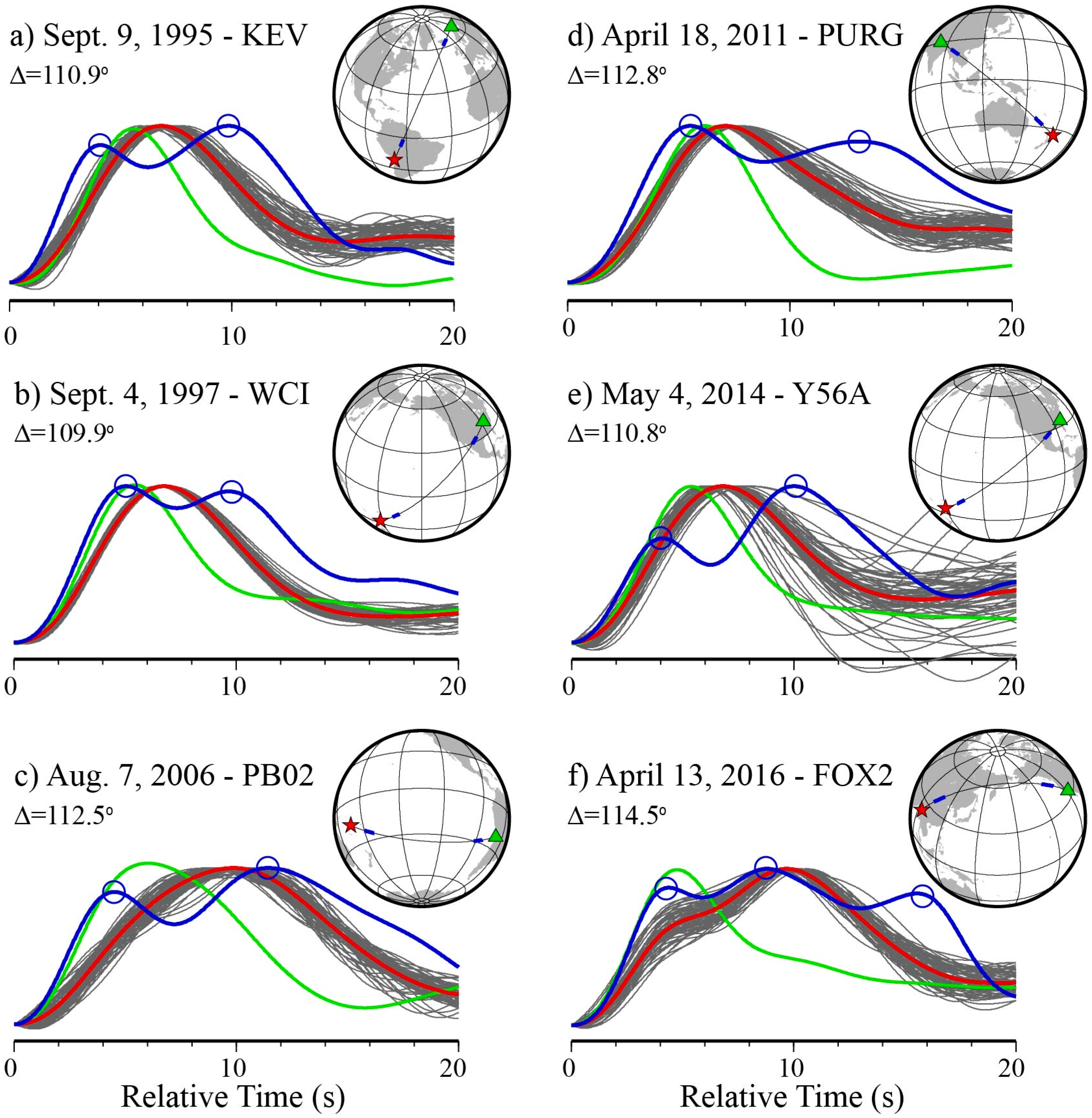
Examples of anomalous detections are shown in Figure 6. In this figure, the blue trace is the data trace and the detected waveform peaks are indicated by the open blue circles. The red trace is the PREM synthetic seismogram convolved with the appropriate triangle function for the event. The gray traces are the 100 realizations of the synthetic with noise added. The empirical SKS wavelet for the event (green trace) is also shown in this figure. We note that, at the distances shown in this figure, SPdKS is already starting to emerge from the SKS arrival in the PREM model, but has not yet emerged as a distinct arrival. Hence, the synthetic trace is broader than the empirical SKS wavelet because the synthetic trace contains both SKS and the imminent emergence of the SPdKS arrival. In all of these examples, the data trace shows more arrivals than the PREM prediction and one of these arrivals stands above the noise level. The examples shown in Figure 6 demonstrate the following points that we observe in these data. First, the anomalous waveform shape is reproducible. See, for example, Figure 6b,e. These records sample similar locations for two distinct events and show similar anomalous waveform behavior. Second, the anomalous waveforms are not restricted to events or stations in specific regions. This is demonstrated in Figure 6, where we have selected anomalous recordings from events in South America, the south Pacific, and southeast Asia and stations in Europe, North and South America, and Asia. Third, this type of anomalous waveform shape appears similar from one region to another. That is, with the exception of the anomaly shown in Figure 6f, all other waveforms appear similar in shape. This could indicate a common underlying origin to all of these anomalous waveforms.
It is important to note that just because an anomaly was detected in a trace sampling a particular location, not all traces sampling that location will necessarily also show an anomaly that our algorithm will detect. There are several reasons for this, that are summarized here. First, each seismogram displays different noise characteristics. Therefore, a trace may have a possible anomalous detection rejected because the arrival isn’t clearly distinguished from the noise. Second, we make a binary classification of anomalous versus non-anomalous on seismograms which display a continuum of behavior. For example, in one trace an anomaly may be detected because a second arrival was detected, but another similarly located waveform may not show a detection because the second arrival hasn’t quite emerged yet. Third, different events have different source-time function durations. Thus, in an event with a longer duration the bifurcation between SKS and SPdKS may occur at a larger epicentral distance, making possible anomalies undetectable at shorter epicentral distances. Fourth, the generation of anomalous waveforms may be highly sensitive to the point where Pd initiates on the CMB. For example, a difference of just 0.5° in Pd inception on the CMB may be enough to trigger or not trigger an anomaly that we can detect [20]. Thus, even though much of the Pd path on the CMB may overlap for two traces, one trace may show an anomaly and the other may not, due to a difference in ULVZ location with respect to where Pd initiates.

3. Results

3.1. Anomaly Detection Results

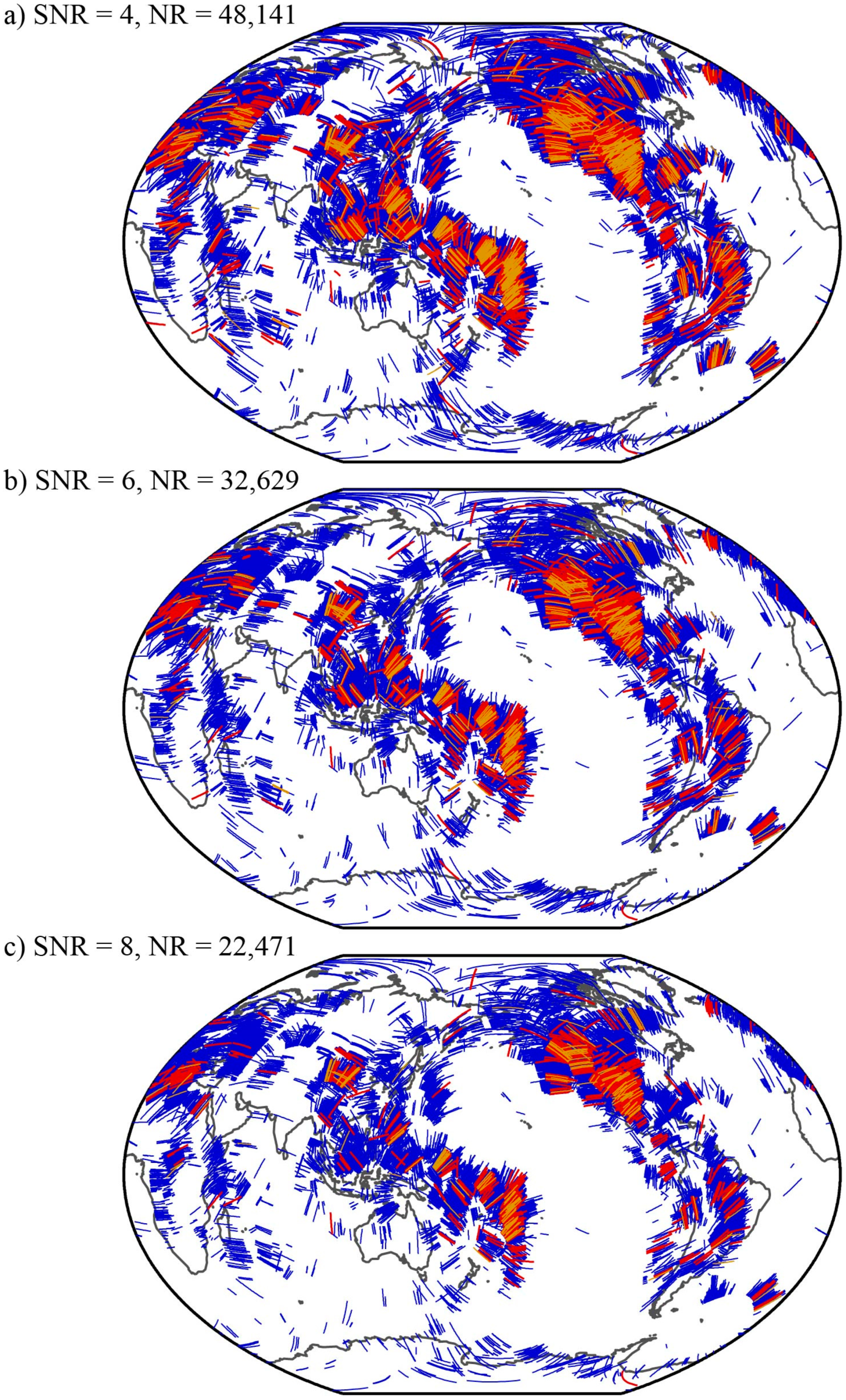
Figure 7 shows the results of running the anomaly detector described in the previous section through our data. This figure shows the Pd segments of SPdKS and SKPdS on the CMB for the traces in which no anomaly was detected (blue lines), an anomalous arrival was detected above the synthetic with added noise 100% of the time (red lines), and an anomalous arrival was detected above the synthetic with added noise 98% of the time (orange lines). The detections are shown for three cases where we only include data with signal-to-noise ratio (SNR) greater than or equal to 4 (Figure 7a), 6 (Figure 7b), or 8 (Figure 7c). It is important to include observations with SNRs on the order of four as the amplitude of SKS tends to decrease upon the emergence of SPdKS at distances around 110° to 112°. A theoretical study by Choy [45] shows that the amplitude spectrum of SKS has a pronounced low at distances around 112° and periods around 5–10 s due to the generation of SPdKS. Unfortunately, the distances and periods with the lowest theoretical amplitudes are exactly the distances and periods where we are searching for anomalies. In choosing what data to include we are thus balancing the tradeoff between (a) large SNR and high-quality data in which we have greater confidence that the anomalous arrival detection is robust, against (b) low SNR in which anomalous detections are more possibly contaminated by noise, but the inclusion of more data. Our desire is to use the highest quality data but not to discard large numbers of waveforms because the SNR typically decreases at these distances. In balancing these considerations, we prefer using a cutoff of SNR = 4 or 6. At an SNR of 4, we found a total of 2222 (out of 48,141 total records) anomalous recordings, and and a SNR of 6 we found a total of 1207 (out of 32,629) anomalous recordings.
It is important to note that, in looking at Figure 7, we plot an anomaly on the Pd-segment for both the source (SPdKS) and receiver (SKPdS) sides. Here, we make no assumptions about where the structure is that gives rise to the anomalous waveforms. One of the challenges in using the SPdKS seismic phase is in this source-/receiver-side ambiguity. We will discuss this further in the subsequent sections. We also note that there is overlap between detections and non-detections. There are multiple reasons for this, as discussed in Section 2. What is key in this figure is that there is geographic coherence in where detections and non-detections are concentrated. It is also apparent that the detections at the slightly lower noise cutoff (98%) primarily overlie the detections at the 100% cutoff, and thus (including the slightly lower noise cutoff) are also useful observations of possible anomalies. In the next section, we use these detections as the starting point for inverting for ULVZ locations.

3.2. Inversion Results

We apply a Bayesian inversion scheme to compute the probability of ULVZ existence from the given sampling of the CMB by SPdKS. In the Bayesian inversion, we treat the potential ULVZ locations as the model parameters. These parameters are treated as random variables expressed in terms of prior probabilities, independent from the data, that express our beliefs about parameters. Then, Bayes’ theorem is used to compute the posterior probability (i.e., the answer) by updating the prior probabilities with the data information, which is incorporated through the likelihood function
𝑝(𝒎|𝒅)=𝐾 𝑝(𝒎)𝑝(𝒅|𝒎),
where 𝑝(𝒎|𝒅) is the probability of model parameters given the data (𝒅) and represents the posterior probability, 𝑝(𝒎) is the prior probability of model parameters (𝒎), 𝑝(𝒅|𝒎) is the probability of the data given the model parameters and is known as the likelihood, and 𝐾 is the proportionality constant that normalizes the probability to 1.
We consider uniform prior between 0 and 1 for all the parameters (𝒎) which suggest that we have no information about the ULVZ locations before we know anything about the data. Therefore, the inversion results are fully driven by the observations. Here, the uniform prior is defined by Beta distribution as,
p ( m ) = B ( α , β ) =   ( α + β 1 ) ! ( α 1 ) ! ( β 1 ) ! m α 1 ( 1 m ) β 1
where 𝛼 and 𝛽 are shape parameters. For uniform prior, shape parameters of the Beta distribution are equal to one (i.e., 𝛼 = 𝛽 = 1).
The data considered here represent the complexity of the SPdKS waveforms defined earlier. We parameterize the CMB on a grid of 2° × 2° boxes. Then, for a randomly chosen box in the lowermost mantle, the likelihood of that box being sampled by anomalous SPdKS or SKPdS waves (y) among the total observation (n) is computed using the Binomial distribution as
p ( d | m ) = ( n y ) m y ( 1 m ) n y
Using Equations (2) and (3), the posterior probability in Equation (1) becomes
p ( m | d ) = K ( α + β 1 ) ! ( α 1 ) ! ( β 1 ) ! m α 1 ( 1 m ) β 1   ( n y ) m y ( 1 m ) n y
This gives a posterior proportional to the beta distribution a,
p ( m | d ) m ( y + α ) 1 ( 1 m ) ( n y + β ) 1   =   B ( y + α , n y + β )
Therefore, the posterior probability density can be expressed in terms of the beta function. In contrast to previous studies of Bayesian waveform inversion of ULVZ properties [46,47], we have an analytical form for the posterior (Equation (5)). An alternative method using a numerical sampling approach could be employed. For example, a Markov Chain Monte Carlo sampling using the Metropolis Hasting acceptance/rejection criterion to compute the posterior is another way to solve this problem. However, this computation would be relatively computationally intensive as we have on the order of 4000 unknowns. Finally, we compute the mean of the posterior probability density to interpret the inversion results.
The mean of the posterior probability density is plotted for each grid cell in Figure 8. Here, the probabilities have been normalized to a maximum of unity, but the large numbers of recordings in the central Pacific create a large spike in probability there, hence we clip the color palette around 0.15 in order to see detail in the other regions as well. In Figure 8 we show two cases for SNR’s of 4 and 6. The solution looks similar in both cases, but the SNR = 4 solution contains more recordings and a few more regions of high-probability ULVZs. This is primarily manifested by some regions that appear ULVZ-like in the SNR = 6 solution which may have more anomalous recordings in the SNR = 4 solution and thus an increased probability of finding a ULVZ. It is important to note that in the construction of this figure we make no assumptions about where a ULVZ may lie along a Pd segment of SPdKS or SKPdS. If a grid cell has an anomalous recording associated with it, regardless of source- or receiver-side Pd leg, then it contributes to an increased probability of ULVZ existing in this location. As such, regions with crossing coverage of Pd segments will have higher probabilities.
The actual size of ULVZs is likely not accurately reflected in Figure 8. Again, this is mainly because we assume perfect in-plane scattering and we make no assumptions of where along the Pd path the ULVZ occurs. In reality, a ULVZ may only exist along a portion of the Pd path and still give rise to anomalous waveforms [20]. Hence, the solutions presented in Figure 8 should not be interpreted as being actual ULVZ boundaries; rather, ULVZs quite possibly exist somewhere within these boundaries.
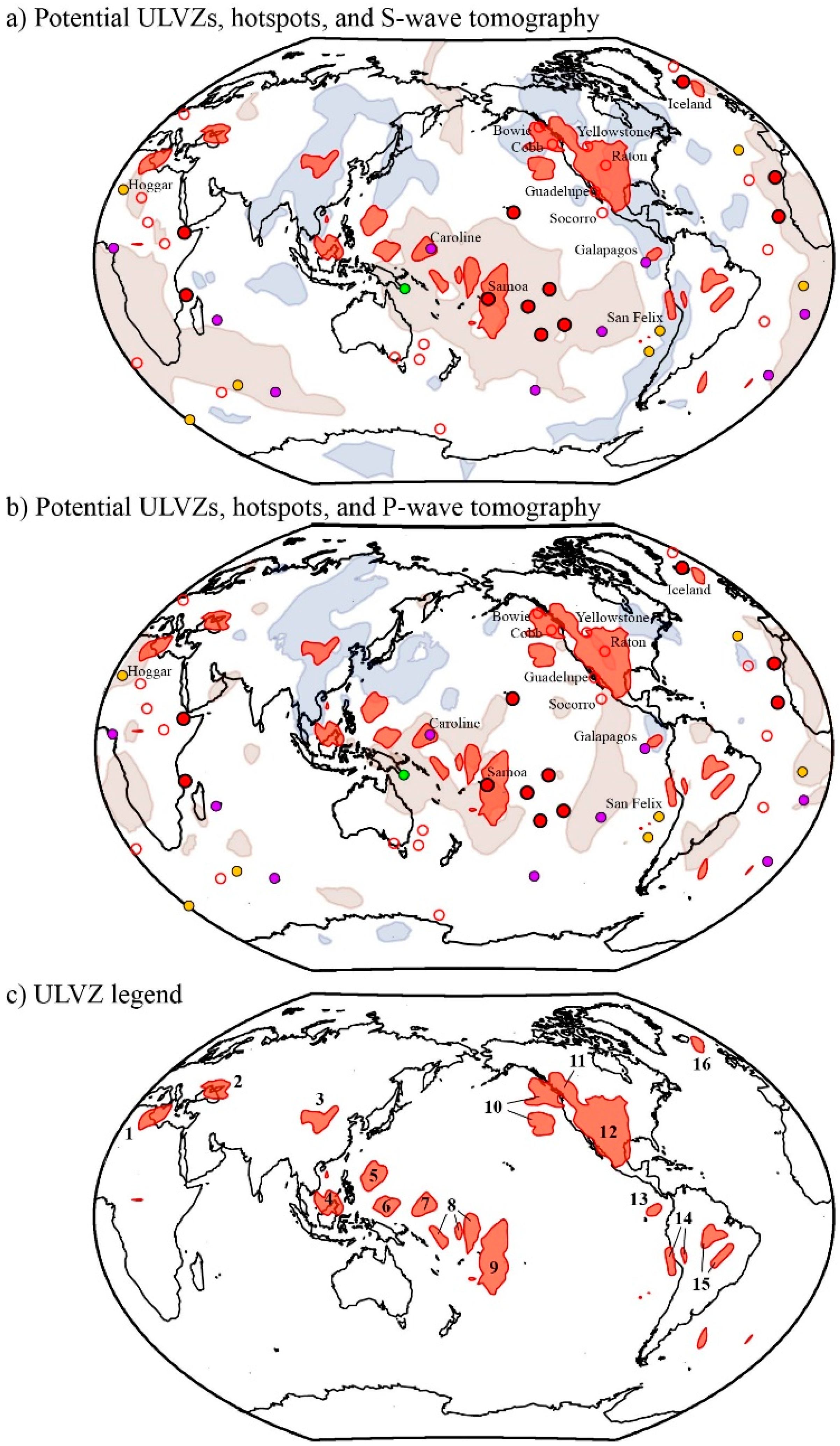
Several regions that have high ULVZ probability are highlighted in Figure 9a,b. We summarize the regions by taking a contour of the ULVZ probability map presented in Figure 8a, showing the regions with the highest probability as dark red regions. For reference, the surface locations of hotspots and contours around LLVP margins are shown. In the next section, we discuss each of the locations where we find the highest probabilities of ULVZ existence.

4. Discussion

We have identified several regions with a high probability of containing ULVZ-like features. In Figure 9c, we have labeled locations that we will discuss in further detail here. Each region identified in Figure 9 has a high concentration of anomalous Pd segments crossing the region. In considering ULVZ existence we will focus on both the presence and density of crossing coverage of Pd segments on the CMB. Such crossing coverage strengthens the argument for ULVZ existence in a given location.

4.1. Region 1—North Africa

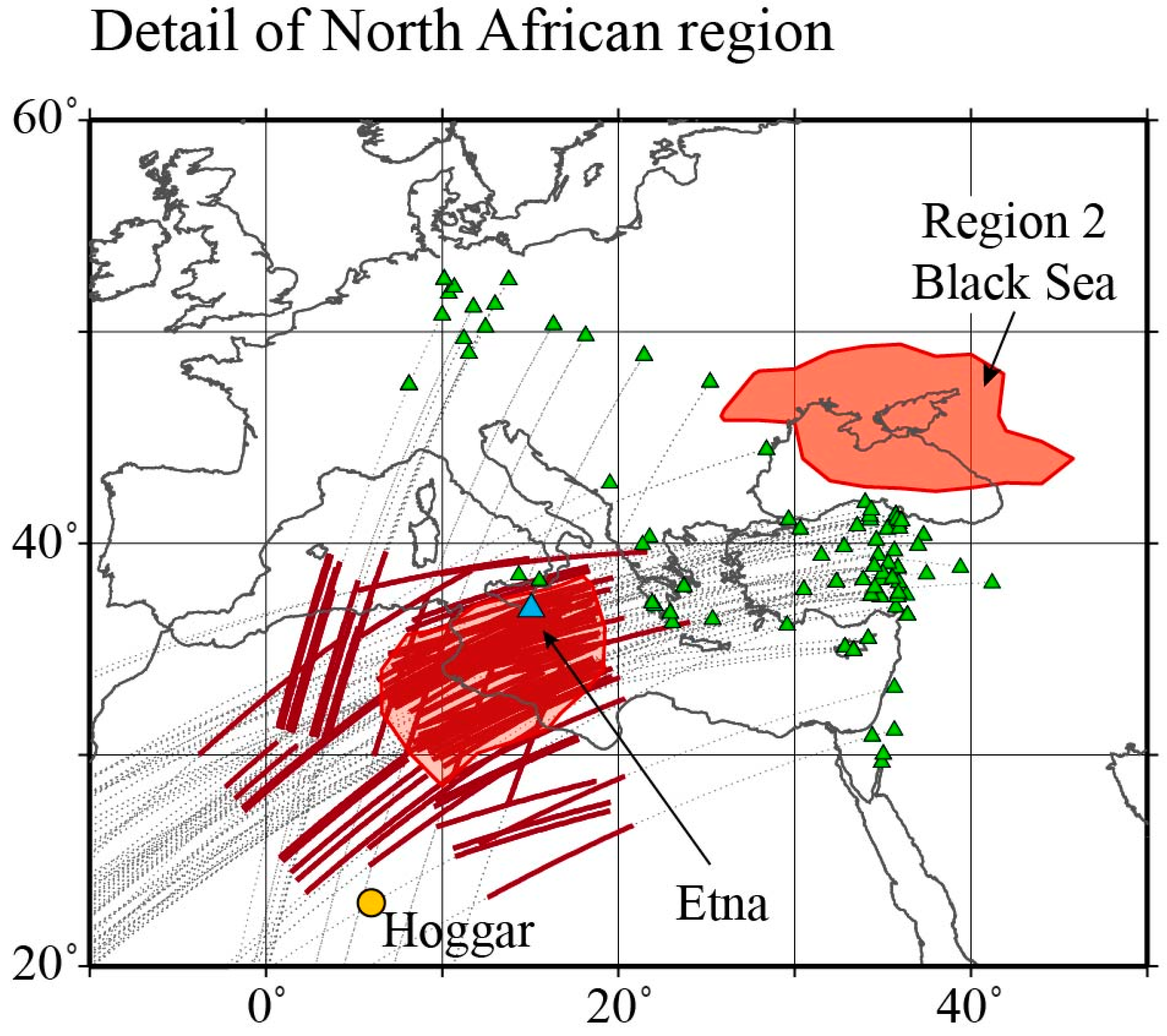
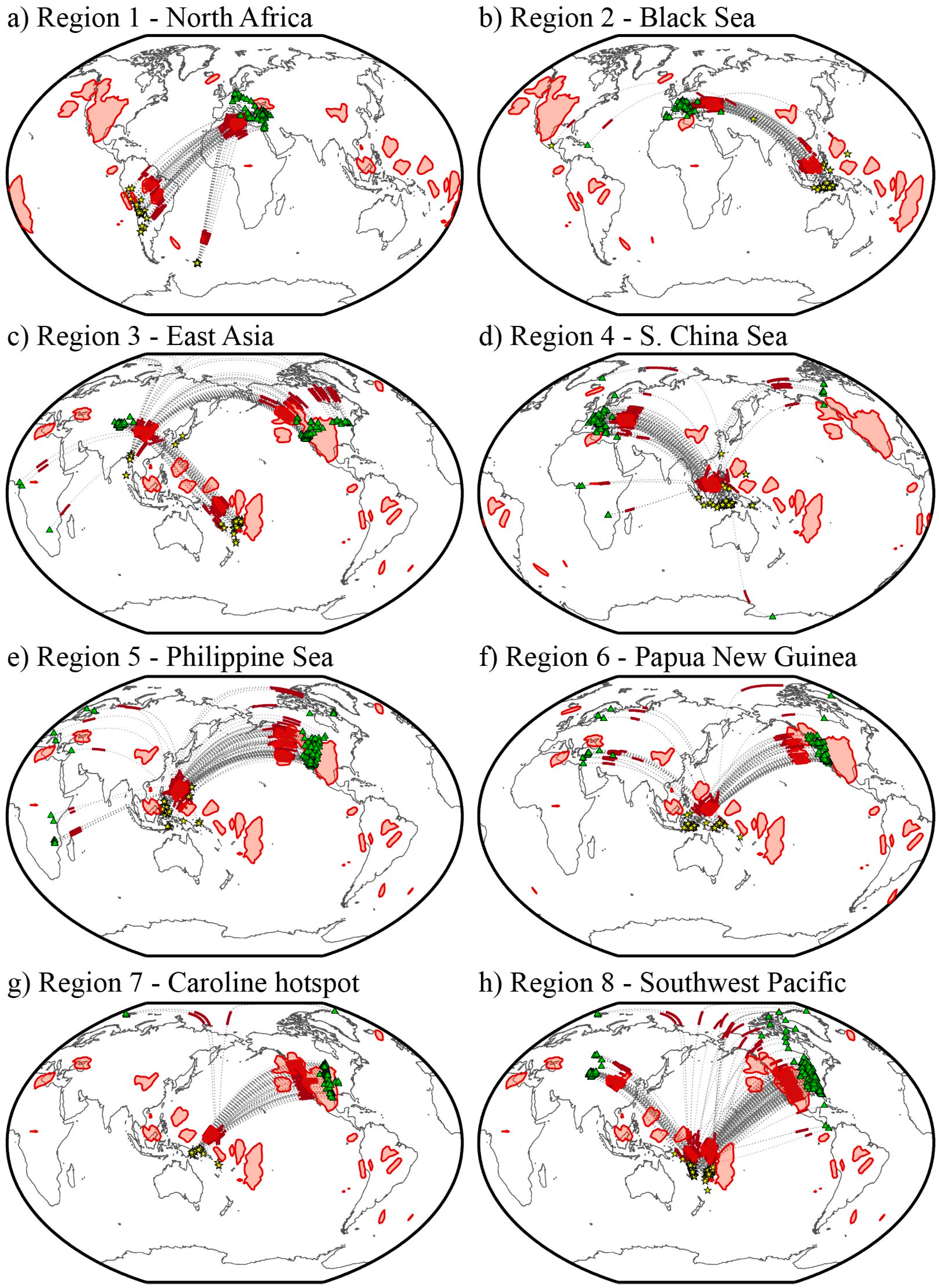
To our knowledge, no ULVZ has been detected in this region previously, with only a couple of seismograms being singled out by Thorne and Garnero [37] as possibly ULVZ-like. We show a detailed plot of the region in Figure 10. In Figure 10, we can see that the area outlined with the highest probability of ULVZ occurrence shows the densest sampling of Pd segments on the CMB. The anomalous waveforms associated with this potential ULVZ are recorded at a variety of stations across a wide range of azimuths. It is also useful to look at a global scale plot of the anomalies, as shown in Figure 11a. This figure shows that the anomalous waveforms are associated with events occurring across much of South America and in the South Sandwich Islands. The common feature of all of these anomalous recordings is the converging and crossing SKPdS coverage beneath Northern Africa, which provides strong evidence for a ULVZ being located here. French and Romanowicz [41] indicate that the Hoggar hotspot, which lies to the south of our most anomalous zone, has a “somewhat resolved” plume extending to the CMB. Their model suggests a plume root approximately 10° to the southwest of our highest probability region. Models of density-driven flow also suggest a possible plume root to the southwest of our highest probabilities for the Hoggar hotspot [48]. Montelli et al. [49] suggest that the Etna volcano shows a continuously resolved plume down to the mantle transition zone. Although Etna lies closer to our region, it has not typically been associated with a hotspot, and whether a potential ULVZ in this region is associated with any surface expression is, at this point, unclear.

4.2. Region 2—Black Sea

No previous evidence has been presented to support the location of a ULVZ in this region (Figure 11b). It is possible that these anomalies are associated with the “Perm” anomaly [50], but our highest probabilities are located at the far southern extent of the Perm anomaly. This region may, however, not contain any ULVZ. We note that all of the anomalous recordings sampling this region also sample the South China Sea region, which, as discussed in Section 4.4, shows highly anomalous recordings with crossing coverage and is supported by studies using other seismic phases. The lack of crossing coverage in the Black Sea region may indicate that this potential ULVZ may be an artefact.

4.3. Region 3—East Asia

This region has been relatively unexplored for ULVZ presence. Thorne and Garnero [37] provided the only previous evidence for an ULVZ located in this region. However, this region shows remarkable crossing coverage of Pd segments (Figure 11c). Anomalous records are found from crossing SKPdS rays from events in the Tonga/Fiji region, and from SPdKS rays from events in Southeast and Eastern Asia. The convergence of such a high concentration of crossing anomalous Pd segments in this region makes this area one of the most likely new ULVZs discovered in this study. It is interesting that the anomalous waveforms in this region look similar to those presented in Thorne et al., 2019 [27]. In that paper, Thorne et al. argued for the existence of large ULVZs at the perimeter of subducted slab material. This particular ULVZ in East Asia is also located in a region that has been associated with past deep subduction [51], and may have a similar origin.

4.4. Region 4—South China Sea

The South China Sea region (Figure 11d) displays a large amount of complexity, with ULVZs already having been inferred by multiple sources. ULVZs have been directly indicated using the seismic phases SPdKS [23] and ScP [52]. In addition, strong scattering from PKP precursors may also be associated with ULVZ presence here [53]. We observe a large number of anomalous waveforms in this region. The additional existence of crossing coverage of anomalous Pd segments adds strength to the argument for ULVZ existence here. Thus, we provide corroborating evidence to previous studies indicating ULVZ existence here. As multiple different seismic phases (e.g., SPdKS, ScP, PKP) all interact with ULVZs here, this may be an ideal region to jointly model multiple seismic phases in an effort to constrain ULVZ properties.

4.5. Region 5—Philippine Sea

The Philippine Sea region (Figure 11e) has shown evidence for ULVZs in previous studies of ScP precursors [47,52], although our region of highest probabilities lies further to the east than previously indicated. Our study shows crossing coverage of Pd segments that point to ULVZ existence. Additional ULVZ evidence exists in that this region displays strong PKP scattering [53].

4.6. Region 6—North of Papua New Guinea

The Papua New Guinea region (Figure 11f) has not previously been identified as containing ULVZs. We observe anomalous waveforms here with crossing coverage from events occurring across Indonesia, making this area interesting for further exploration and confirmation of ULVZ presence.

4.7. Region 7—Caroline Hotspot

The Caroline hotspot region (Figure 11g) also has not previously been implicated for ULVZ presence. In this study, we mostly observe anomalous arrivals from one source region recorded in North America. However, a handful of arrivals with crossing coverage also exist and so we cannot rule out a ULVZ here. French and Romanowicz [41] indicate a “clearly resolved” plume conduit from surface to CMB for the Caroline hotspot, and Montelli et al. [49] show a P-wave velocity anomaly extending from the surface to depths greater than 1000 km. Due to the limited amount of crossing coverage we are hesitant to declare ULVZ existence here, but the region is potentially ULVZ-like and should be explored further.

4.8. Region 8—Southwest Pacific

The Southwest Pacific region (Figure 11h) has been argued for ULVZ existence in several past studies using the seismic phases ScP [54,55], PKP precursors [6,56], and SPdKS [23,37]. Based on excellent crossing coverage, this region appears highly ULVZ-like in our present results. We note, however, that many anomalous recordings for this region also cross another highly anomalous zone in northern Mexico [27]. Thus, anomalies present here may result from ULVZs located on both source- and receiver-sides of the path.

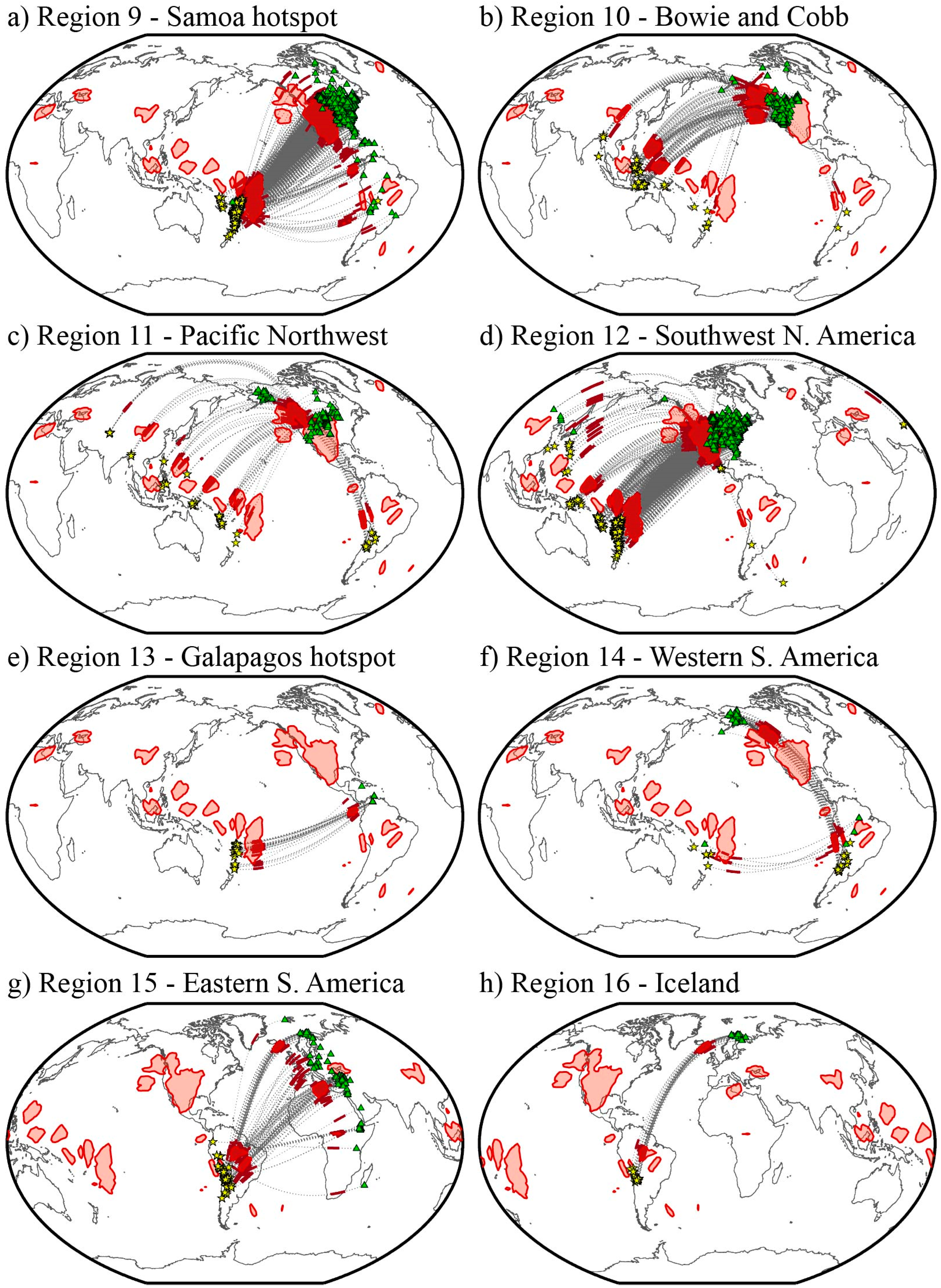
4.9. Region 9—Samoa Hotspot

A broad region of highly anomalous waveforms beneath the Samoa hotspot (Figure 12a) has also been detected in several previous SPdKS studies [20,31,37]. This study provides additional support for ULVZ presence here. We again note that some of these recordings also pass through a highly anomalous ULVZ in northern Mexico and may contain both source- and receiver-side ULVZ signatures.

4.10. Region 10—Bowie and Cobb Hotspots

We see a large convergence of anomalous Pd segments beneath the general area of the Bowie and Cobb hotspots. Previous studies investigating this region did not show any evidence for ULVZs here [57,58]. Our anomalous recordings all sample other regions with high concentrations of ULVZ-like signals, most of which have crossing coverage which argues for ULVZ sources on the source-sides as opposed to under this region. Hence, it may just be fortuitous that we see a high probability for ULVZs in this location.

4.11. Region 11—Pacific Northwest

The region beneath the Pacific Northwest has been implicated for ULVZ structure by one previous study investing SKS coda [59]. Here, we see good evidence that a ULVZ exists here with a large amount of crossing coverage from disparate source regions. From the crossing coverage we observe it may be more likely that a ULVZ exists in this location than in western South America, as discussed in Section 4.14.

4.12. Region 12—Southwestern North America

The southwestern portion of North America (Figure 12d) shows a vast convergence of anomalous waveforms. As our ULVZ probability map places possible ULVZ extent along the full length of the Pd segments, we see an artificially large ULVZ zone here. Nonetheless, it is likely that some ULVZ structure exists here. ULVZs have been detected in this region before. Havens and Revenaugh [9] used ScP arrivals to locate a ULVZ in northern Mexico. Thorne et al. [27] showed evidence for ULVZs beneath northern Mexico and Louisiana using a combination of SPdKS recordings from broadband seismic stations and Hi-net tiltmeter recordings. These Hi-net recordings, not used in this present study, used earthquakes occurring in Central America and recorded in Japan which provided source-side SPdKS evidence for a ULVZ here. Furthermore, recent evidence has been put forth from tomographic imaging that the source of the Yellowstone hotspot lies near the Mexico–California border [60]. Considering crossing coverage of Pd rays in this region, it is likely that ULVZs exist in this region, but the extent is likely smeared in our map.

4.13. Region 13—Galapagos Hotspot

We find a small concentration of anomalous waveforms located directly beneath the Galapagos hotspot (Figure 12e). However, these recordings show no crossing coverage, are primarily recorded at a single seismic station, and all interact with possible anomalous structure in the Samoa hotspot region. Thus, we find it difficult to conclude with certainty that a ULVZ lies in this particular region. However, one previous study using SKS and SKKS travel-times indicate a possible ULVZ rooted at this location [61] and a recent study of Sdiff coda also suggests a ULVZ located here [62]. Thus, we cannot simply rule out a ULVZ existing here. However, evidence from tomography suggests that the Galapagos hotspot has a deep plume root [41,49], yet this root appears to lie to the east of the surface expression of the hotspot. Thus, it is unclear if the concentration of anomalies we observe here are associated with a deep root to the Galapagos hotspot.

4.14. Region 14—Western South America

No ULVZ evidence has been presented in this location previously. These anomalous recordings are dominated by a handful of South American events recorded in Alaska (see also, Section 4.11). Both source- and receiver-side recordings show a narrow azimuthal range of anomalies with almost no crossing coverage on the source-side beneath South America. That highly anomalous paths exist along this corridor is not in question, but whether they are associated with ULVZs in South or North America is unclear. It is possible that some signal of the San Felix hotspot (see Figure 9) is being observed here. French and Romanowicz [41] show a continuous conduit from the CMB to the San Felix hotspot. Hence, it is possible that we are seeing ULVZ signature in this region.

4.15. Region 15—Eastern South America

Some previous evidence has been put forth for the existence of ULVZs in the eastern part of South America. Most notably, PKP waves sampling the Amazon Basin region show large post-cursor arrivals that may be associated with a ULVZ [12]. We observe several anomalous arrivals here with crossing coverage that may indicate ULVZ presence. Although some of these arrivals may be sampling the Iceland or North Africa regions, we see anomalous rays at a large range of azimuths, recorded at stations extending from Iceland to Madagascar, that cross each other beneath South America. If a ULVZ exists here, it may also lie near the boundary of deep subducted slab material.

4.16. Region 16—Iceland

Two previous studies have found evidence for a large ULVZ beneath Iceland in the same location we indicate here. One older study focused on a handful of SPdKS recordings [5] and a more recent study used a large set of Sdiff coda observations [19]. Our data show a high concentration of excellent quality SPdKS recordings with anomalous waveforms in the Iceland region (see e.g., Figure 6a), corroborating previous studies that suggest that a large ULVZ likely exists at the base of the Iceland hotspot.

5. Conclusions

In this paper we have searched for anomalous SPdKS waveforms in a new global set of seismic recordings. We used a machine learning algorithm to assist in assembling this new large data set and developed an automated routine to detect anomalies in the SPdKS wavefield. From these anomalous waveforms we have identified several regions as having a high probability of ULVZ existence by Bayesian inference. Several of these regions, such as beneath the South China Sea, Samoa, Iceland, the Southwest Pacific and Northern Mexico, have been previously described as ULVZ-like. Thus, we corroborate those findings here. We also identify several new regions as being ULVZ-like. In particular, we see excellent evidence for newly described ULVZs beneath Northern Africa, East Asia, and the Philippine Sea. We also provide additional evidence for ULVZ existence in other regions that weakly showed ULVZ evidence in previous studies, such as beneath the Pacific Northwest or Eastern South America. Intriguing evidence also exists for previously unidentified ULVZs beneath the Caroline, Galapagos, and San Felix hotspots, but cannot be securely confirmed in this study.
The results of this study highlight the regions that contain the most anomalous seismic waveforms used in studying ULVZs. Only two previous studies have extensively considered these types of anomalous waveforms [20,27] and demonstrated a high degree of reliability in this anomalous waveform shape, although it should be noted that such anomalous waveforms have been observed in other previous studies, even if not specifically singled out. Nevertheless, the primary regions in which these anomalies occur were previously limited to Samoa and Northern Mexico. In this paper we show that such anomalous recordings occur much more frequently, and can also be observed in regions where ULVZs have previously been inferred but such anomalous waveforms have not been identified. It is striking how similar in waveform shape the anomalous recordings appear (see e.g., Figure 6). This similarity in waveform shape may suggest a common origin to all of the features giving rise to these anomalies.
The potential ULVZ locations identified here should not be considered as the only places ULVZs exist within our covered area. First, we identified anomalies with a strict detector that limits positive identifications to those that clearly stand above the noise. Other anomalous recordings may exist within the noise that we rule out here. Second, we only searched for one type of anomaly. Previous efforts have observed data with this kind of anomaly, and therefore we searched for it. However, other kinds of waveform anomalies may also exist that we don’t yet know to look for. Further forward modeling may elucidate other novel types of waveform features. Third, the data processing utilized in this paper involved low pass filtering these seismograms with a corner period of 6 s. This low pass filter has the effect of smoothing the recordings, and as a result it was easier to implement our anomaly detector. However, this may have the undesired effect of smoothing over some of the more subtle anomalous recordings. In future efforts, we will consider these data with a higher frequency cutoff in the filtering stage. Such an effort may reveal even more anomalous regions.
It is also important to consider the regions where we don’t find ULVZ existence. In this work, we focus on the most anomalous recordings, which could be indicative of the most anomalous ULVZ-like regions. There are many areas in our study that do not show evidence for highly anomalous recordings (dark blue regions in Figure 8). For example, we find relatively little evidence for ULVZs in the vicinity of Africa. However, this does not necessarily suggest that ULVZs do not exist in these regions, as evidence for ULVZs may come from more subtle waveform anomalies than presented here. We also haven’t yet addressed the source-/receiver-side ambiguity. Addressing this ambiguity may have the effect of increasing the area of ULVZ non-existence. Furthermore, we note that it is generally easier to demonstrate the existence of a feature than non-existence, and refrain from making conclusions about ULVZ non-existence at this time.
We used a Bayesian method to invert for probability of ULVZ existence. This method worked well to identify the locations with the highest concentration of Pd rays. However, a significant challenge in using the SPdKS/SKPdS ensemble of arrivals is the ambiguity between source- and receiver-sides. In our discussion, we argued for ULVZ presence or non-presence primarily based on the density of Pd rays and whether or not crossing coverage of Pd rays existed. However, such constraints could be included in the inversion process itself. We are currently testing other inversion methods to find probable ULVZ locations. In particular, it may be useful to search for the most parsimonious ULVZ distribution—that is, to search for the minimum number of ULVZs that can explain our observations. In such a scenario, a single anomalous arrival is potentially explained by a ULVZ on only the source- or receiver-side. Areas with large crossing coverage will require a ULVZ, whereas areas with no crossing coverage may not require a ULVZ. Such an inversion procedure may generate a different ULVZ distribution map than presented in this paper. Furthermore, we assume nothing in this paper about where a ULVZ is located along a given Pd segment, assuming it just lies somewhere along the path. Future efforts should also include information on the sensitivity to ULVZ position with respect to generating these anomalous waveforms.
The ULVZ distribution we present here does not show an obvious correlation with hotspots or LLVP edges as inferred from S-wave tomography. Most of the ULVZs we observe in relation to the Pacific LLVP appear to lie in the center of the LLVP and not near its edges, however, we must note that we have limited coverage at its boundaries, and tomography models are naturally smoothed as well. We find almost no ULVZs in the vicinity of the African LLVP, but, again, we have limited coverage in this region. Relative to recent P-wave tomography, our ULVZ distribution appears to be much more similar to the Pacific LLVP distribution of low velocities. There does appear to be a connection between ULVZs and some hotspots, and we have uncovered more potential hotspots rooted with ULVZs. Nevertheless, in this study we only use a subset of the SPdKS data in our collection and only one method to identify possible ULVZ locations. Thus, we find it premature to draw correlations between ULVZs and other Earth features.

Supplementary Materials

The following are available online at https://www.mdpi.com/2075-163X/10/3/211/s1, Video S1: PREM wavefield, Video S2: ULVZ wavefield.

Author Contributions

Conceptualization, M.S.T. and T.N.-M.; methodology, M.S.T. and S.P.; software, M.S.T., S.P., and K.L.; validation, M.S.T. and S.P.; data curation, M.S.T.; writing—original draft preparation, M.S.T.; writing—review and editing, M.S.T., S.P., K.L., T.N.-M. And J.K.W.; visualization, M.S.T., S.P., and K.L.; funding acquisition, M.S.T., J.K.W., and T.N.-M. All authors have read and agreed to the published version of the manuscript.

Funding

M.S.T. and S.P. were partially supported by NSF grant EAR-1723081. K.L. and T.N.-M. were partially supported by NERC grant NE/R012199/1.

Acknowledgments

We thank two anonymous reviewers whose comments improved this ms. IRIS and SCEDC data were collected using the SOD utility [63]. We acknowledge the University of Utah Center for High Performance Computing for computer resources and support, as well as the UK’s supercomputing facility ARCHER, where some of the modeling was undertaken. Figures were drawn using the Generic Mapping Tools [64]. Data processing and analysis utilized SACTOOLS [65]. All data are freely available online from the IRIS, SCEDC, ORFEUS, and CNSN data centers.

Conflicts of Interest

The authors declare no conflict of interest.

References

  1. Garnero, E.J.; Grand, S.P.; Helmberger, D.V. Low P-wave velocity at the base of the mantle. Geophys. Res. Lett. 1993, 20, 1843–1846. [Google Scholar] [CrossRef]
  2. Garnero, E.J.; Helmberger, D.V. A very slow basal layer underlying large-scale low-velocity anomalies in the lower mantle beneath the Pacific: Evidence from core phases. Phys. Earth Planet. Inter. 1995, 91, 161–176. [Google Scholar] [CrossRef]
  3. Yu, S.; Garnero, E.J. Ultralow velocity zone locations: A global assessment. Gcubed 2018, 19, 1–19. [Google Scholar] [CrossRef]
  4. Revenaugh, J.; Meyer, R. Seismic Evidence of Partial Melt Within a Possibly Ubiquitous Low-Velocity Layer at the Base of the Mantle. Science 1997, 277, 670–673. [Google Scholar] [CrossRef]
  5. Helmberger, D.V.; Wen, L.; Ding, X. Seismic evidence that the source of the Iceland hotspot lies at the core-mantle boundary. Nature 1998, 396, 251–255. [Google Scholar] [CrossRef]
  6. Vidale, J.E.; Hedlin, M.A.H. Evidence for partial melt at the core-mantle boundary north of Tonga from the strong scattering of seismic waves. Nature 1998, 391, 682–685. [Google Scholar] [CrossRef]
  7. Williams, Q.; Garnero, E.J. Seismic Evidence for Partial Melt at the Base of Earth’s Mantle. Science 1996, 273, 1528–1530. [Google Scholar] [CrossRef] [Green Version]
  8. Reasoner, C.; Revenaugh, J. ScP constraints on ultralow-velocity zone density and gradient thickness beneath the Pacific. J. Geophys. Res. 2000, 105, 28173–28182. [Google Scholar] [CrossRef]
  9. Havens, E.; Revenaugh, J. A broadband seismic study of the lowermost mantle beneath Mexico: Constraints on ultralow velocity zone elasticity and density. J. Geophys. Res. 2001, 106, 30809–30820. [Google Scholar] [CrossRef]
  10. Simmons, N.A.; Grand, S.P. Partial melting in the deepest mantle. Geophys. Res. Lett. 2002, 29. [Google Scholar] [CrossRef]
  11. Rost, S.; Garnero, E.J.; Williams, Q.; Manga, M. Seismological constraints on a possible plume root at the core-mantle boundary. Nature 2005, 435, 666–669. [Google Scholar] [CrossRef] [PubMed]
  12. Zou, Z.; Leyton, F.; Koper, K.D. Partial melt in the lowermost mantle near the base of a plume. Geophys. J. Int. 2007, 168, 809–817. [Google Scholar] [CrossRef] [Green Version]
  13. Manga, M.; Jeanloz, R. Implications of a metal-bearing chemical boundary layer in D” for mantle dynamics. Geophys. Res. Lett. 1996, 23, 3091–3094. [Google Scholar] [CrossRef]
  14. Wicks, J.; Jackson, J.M.; Sturhahn, W.; Zhang, D. Sound velocity and density of magnesiowüstites: Implications for ultralow-velocity zone topography. Geophys. Res. Lett. 2017, 44, 2148–2158. [Google Scholar] [CrossRef]
  15. Wicks, J.K.; Jackson, J.M.; Sturhahn, W. Very low sound velocities in iron-rich (Mg,Fe)O: Implications for the core-mantle boundary region. Geophys. Res. Lett. 2010, 37. [Google Scholar] [CrossRef] [Green Version]
  16. Brown, S.P.; Thorne, M.S.; Miyagi, L.; Rost, S. A compositional origin to ultralow-velocity zones. Geophys. Res. Lett. 2015, 42, 1–7. [Google Scholar] [CrossRef]
  17. Buffett, B.A.; Garnero, E.J.; Jeanloz, R. Sediments at the Top of Earth’s Core. Science 2000, 290, 1338–1342. [Google Scholar] [CrossRef]
  18. Williams, Q.; Revenaugh, J.; Garnero, E.J. A Correlation Between Ultra-Low Basal Velocities in the Mantle and Hot Spots. Science 1998, 281, 546–549. [Google Scholar] [CrossRef]
  19. Yuan, K.; Romanowicz, B. Seismic evidence for partial melting at the root of major hot spot plumes. Science 2017, 357, 393–397. [Google Scholar] [CrossRef] [Green Version]
  20. Thorne, M.S.; Garnero, E.J.; Jahnke, G.; Igel, H.; McNamara, A.K. Mega Ultra Low Velocity Zone and Mantle Flow. Earth Planet. Sci. Lett. 2013, 364, 59–67. [Google Scholar] [CrossRef]
  21. Cottaar, S.; Romanowicz, B. An unusually large ULVZ at the base of the mantle near Hawaii. Earth Planet. Sci. Lett. 2012, 355–356, 213–222. [Google Scholar] [CrossRef]
  22. Helmberger, D.V.; Ni, S.; Wen, L.; Ritsema, J. Seismic evidence for ultralow-velocity zones beneath Africa and eastern Atlantic. J. Geophys. Res. 2000, 105, 23865–23878. [Google Scholar] [CrossRef]
  23. Jensen, K.J.; Thorne, M.S.; Rost, S. SPdKS analysis of ultralow-velocity zones beneath the western Pacific. Geophys. Res. Lett. 2013, 40, 1–5. [Google Scholar] [CrossRef] [Green Version]
  24. Ni, S.; Helmberger, D.V. Horizontal transition from fast to slow structures at the core-mantle boundary; South Atlantic. Earth Planet. Sci. Lett. 2001, 187, 301–310. [Google Scholar] [CrossRef]
  25. Vanacore, E.A.; Rost, S.; Thorne, M.S. Ultralow-velocity zone geometries resolved by multidimensional waveform modeling. Geophys. J. Int. 2016. [Google Scholar] [CrossRef] [Green Version]
  26. Sun, D.; Helmberger, D.V.; Lai, V.H.; Gurnis, M.; Jackson, J.M.; Yang, H.-Y. Slab control on the northeastern edge of the mid-Pacific LLSVP near Hawaii. Geophys. Res. Lett. 2019, 46, 3142–3152. [Google Scholar] [CrossRef]
  27. Thorne, M.S.; Takeuchi, N.; Shiomi, K. Melting at the edge of a slab in the deepest mantle. Geophys. Res. Lett. 2019, 46, 8000–8008. [Google Scholar] [CrossRef]
  28. Bower, D.J.; Wicks, J.K.; Gurnis, M.; Jackson, J.M. A geodynamic and mineral physics model of a solid-state ultralow-velocity zone. Earth Planet. Sci. Lett. 2011, 303, 193–202. [Google Scholar] [CrossRef] [Green Version]
  29. Garnero, E.J.; Helmberger, D.V. Further structural constraints and uncertainties of a thin laterally varying ultralow-velocity layer at the base of the mantle. J. Geophys. Res. 1998, 103, 12495–12509. [Google Scholar] [CrossRef] [Green Version]
  30. Ni, S.; Helmberger, D.V. Probing an Ultra-low velocity zone at the Core Mantle Boundary with P and S Waves. Geophys. Res. Lett. 2001, 28, 2345–2348. [Google Scholar] [CrossRef] [Green Version]
  31. Wen, L.; Helmberger, D.V. A two-dimensional P-SV hybrid method and its application to modeling localized structures near the core-mantle boundary. J. Geophys. Res. 1998, 103, 17901–17918. [Google Scholar] [CrossRef] [Green Version]
  32. Dziewonski, A.M.; Anderson, D.L. Preliminary reference Earth model. Phys. Earth Planet. Inter. 1981, 25, 297–356. [Google Scholar] [CrossRef]
  33. Leng, K.; Nissen-Meyer, T.; van Driel, M.; Al-Attar, D. AxiSEM3D: A new fast method for global wave propagation in 3-D Earth models with undulating discontinuities. In Abstract DI23A-2596 Presented at 2016 Fall Meeting; AGU: San Francisco, CA, USA, 2016. [Google Scholar]
  34. Leng, K.; Nissen-Meyer, T.; van Driel, M.; Hosseini, K.; Al-Attar, D. AxiSEM3D: Broad-band seismic wavefields in 3-D global earth models with undulating discontinuities. Geophys. J. Int. 2019, 217, 2125–2146. [Google Scholar] [CrossRef] [Green Version]
  35. Garnero, E.J.; Jeanloz, R. Fuzzy Patches on the Earth’s Core-Mantle Boundary? Geophys. Res. Lett. 2000, 27, 2777–2780. [Google Scholar] [CrossRef] [Green Version]
  36. Rost, S.; Revenaugh, J. Seismic Detection of Rigid Zones at the Top of the Core. Science 2001, 294, 1911–1914. [Google Scholar] [CrossRef] [Green Version]
  37. Thorne, M.S.; Garnero, E.J. Inferences on ultralow-velocity zone structure from a global analysis of SPdKS waves. J. Geophys. Res. 2004, 109. [Google Scholar] [CrossRef]
  38. Earthquakes Canada, N.R.C. Continuous Waveform Archive, [email protected]. Available online: https://earthquakescanada.nrcan.gc.ca/stndon/CNSN-RNSC/index-en.php (accessed on 31 December 2018).
  39. Valentine, A.P.; Woodhouse, J.H. Approaches to automated data selection for global seismic tomography. Geophys. J. Int. 2010, 182, 1001–1012. [Google Scholar] [CrossRef] [Green Version]
  40. VanDecar, J.C.; Crosson, R.S. Determination of teleseismic relative phase arrival times using multi-channel cross-correlation and least squares. Bull. Seismol. Soc. Am. 1990, 80, 150–169. [Google Scholar]
  41. French, S.W.; Romanowicz, B. Broad plumes rooted at the base of the Earth’s mantle beneath major hotspots. Nature 2015, 525, 95–99. [Google Scholar] [CrossRef]
  42. Simmons, N.A.; Forte, A.M.; Boschi, L.; Grand, S.P. GyPSuM: A joint tomographic model of mantle density and seismic wave speeds. J. Geophys. Res. Solid Earth 2010, 115, 1–24. [Google Scholar] [CrossRef]
  43. Hosseini, K.; Sigloch, K.; Tsekhmistrenko, M.; Zaheri, A.; Nissen-Meyer, T.; Igel, H. Global mantle structure from multifrequency tomography using P, PP and P-diffracted waves. Geophys. J. Int. 2020, 220, 96–141. [Google Scholar] [CrossRef]
  44. Jahnke, G. Methods for Seismic Wave Propagation on Local and Global Scales with Finite Differences; Ludwig-Maximilians-Universität: München, Germany, 2009. [Google Scholar]
  45. Choy, G.L. Theoretical seismograms of core phases calculated by frequency-dependent full wave theory, and their interpretation. Geophys. J. R. Astron. Soc. 1977, 51, 275–312. [Google Scholar] [CrossRef] [Green Version]
  46. Pachhai, S.; Tkalčić, H.; Dettmer, J. Bayesian inference for ultralow velocity zones in the Earth’s lowermost mantle: Complex ULVZ beneath the east of the Philippines. J. Geophys. Res. Solid Earth 2014, 119, 8346–8365. [Google Scholar] [CrossRef]
  47. Pachhai, S.; Dettmer, J.; Tkalčić, H. Ultra-low velocity zones beneath the Philippine and Tasman Seas revealed by a trans-dimensional Bayesian waveform inversion. Geophys. J. Int. 2015, 203, 1302–1318. [Google Scholar] [CrossRef]
  48. Steinberger, B. Plumes in a convecting mantle: Models and observations for individual hotspots. J. Geophys. Res. 2000, 105, 11,127–111,152. [Google Scholar] [CrossRef]
  49. Montelli, R.; Nolet, G.; Dahlen, F.A.; Masters, G. A catalogue of deep mantle plumes: New results from finite frequency tomography. Geochem. Geophys. Geosyst. 2006, 7. [Google Scholar] [CrossRef]
  50. Lekic, V.; Cottaar, S.; Dziewonski, A.M.; Romanowicz, B. Cluster analysis of global lower mantle tomography: A new class of structure and implications for chemical heterogeneity. Earth Planet. Sci. Lett. 2012, 357–358, 68–77. [Google Scholar] [CrossRef]
  51. Grand, S.P. Mantle shear-wave tomography and the fate of subducted slabs. Philos. Trans. R. Soc. Lond. A 2002, 360, 2475–2491. [Google Scholar] [CrossRef]
  52. Idehara, K.; Yamada, A.; Zhao, D. Seismological constraints on the ultralow velocity zones in the lowermost mantle from core-reflected waves. Phys. Earth Planet. Inter. 2007, 165, 25–46. [Google Scholar] [CrossRef]
  53. Yao, J.; Wen, L. Seismic structure and ultra-low velocity zones at the base of the Earth’s mantle beneath Southeast Asia. Phys. Earth Planet. Inter. 2014, 233, 103–111. [Google Scholar] [CrossRef]
  54. Rost, S.; Garnero, E.J.; Stefan, W. Thin and intermittent ultralow-velocity zones. J. Geophys. Res. 2010, 115. [Google Scholar] [CrossRef] [Green Version]
  55. Garnero, E.J.; Vidale, J.E. ScP; a probe of ultralow velocity zones at the base of the mantle. Geophys. Res. Lett. 1999, 26, 377–380. [Google Scholar] [CrossRef] [Green Version]
  56. Wen, L.; Helmberger, D.V. Ultra-Low Velocity Zones Near the Core-Mantle Boundary from Broadband PKP Precursors. Science 1998, 279, 1701–1703. [Google Scholar] [CrossRef] [PubMed] [Green Version]
  57. Persh, S.E.; Vidale, J.E.; Earle, P.S. Absence of short-period ULVZ precursors to PcP and ScP from two regions of the CMB. Geophys. Res. Lett. 2001, 28, 387–390. [Google Scholar] [CrossRef] [Green Version]
  58. Castle, J.C.; van der Hilst, R.D. The core-mantle boundary under the Gulf of Alaska: No ULVZ for shear waves. Earth Planet. Sci. Lett. 2000, 176, 311–321. [Google Scholar] [CrossRef]
  59. Rondenay, S.; Fischer, K.M. Constraints on localized core-mantle boundary structure from multichannel, broadband SKS coda analysis. J. Geophys. Res. 2003, 108. [Google Scholar] [CrossRef] [Green Version]
  60. Nelson, P.L.; Grand, S.P. Lower-mantle plume beneath the Yellowstone hotspot revealed by core waves. Nat. Geosci. 2018, 11, 280–284. [Google Scholar] [CrossRef]
  61. Vanacore, E.; Niu, F. Characterization of the D” beneath the Galapagos Islands using SKKS and SKS waveforms. Earthq. Sci. 2011, 24, 87–99. [Google Scholar] [CrossRef] [Green Version]
  62. Cottaar, S.; Li, Z. An ultra-low velocity zone beneath the Galapagos hotspot. In American Geophysical Union Fall Meeting 2019; abstract DI53A-0043; AGU: San Francisco, CA, USA, 2019. [Google Scholar]
  63. Owens, T.J.; Crotwell, H.P.; Groves, C.; Oliver-Paul, P. SOD: Standing Order for Data. Seismol. Res. Lett. 2004, 75, 515–520. [Google Scholar] [CrossRef]
  64. Wessel, P.; Smith, W.H.F. New, Improved Version of Generic Mapping Tools Released. Eos Trans. Am. Geophys. Union 1998, 79, 579. [Google Scholar] [CrossRef]
  65. Thorne, M.S. SACTOOLS v1.0.0. Available online: https://zenodo.org/record/1314738#.XlXgtEoRXIU (accessed on 18 July 2018). [CrossRef]
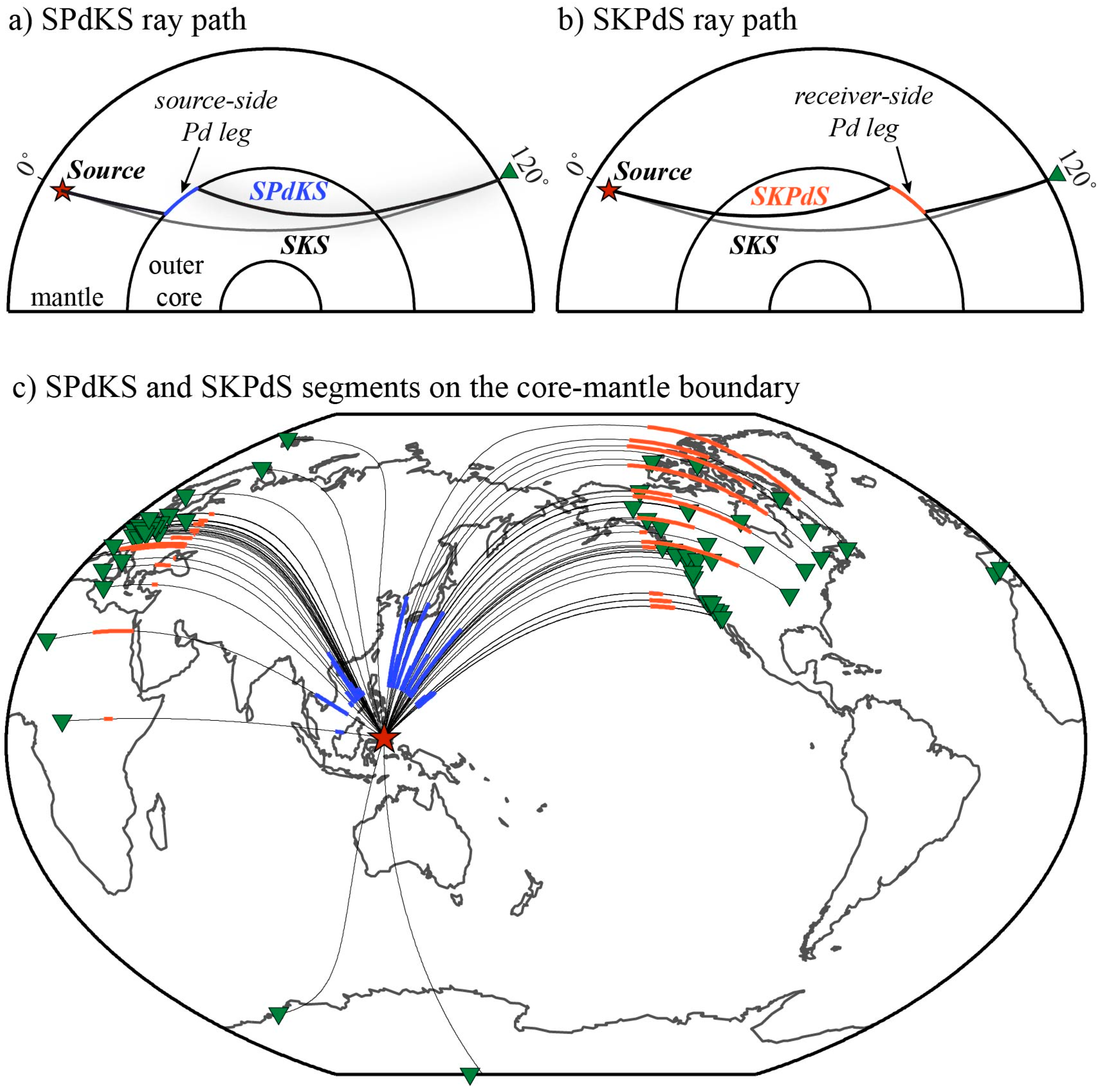
Figure 1. (a) Ray path for SKS (black) and SPdKS (blue) for a receiver located at an epicentral distance of 120°. (b) Ray path for SKS (black) and SKPdS (orange). In (a) and (b), the Pd portion of the ray path is indicated. (c) Example Pd legs projected onto the core–mantle boundary (CMB) are shown for an event occurring on 28 February 1996. The source-side (SPdKS) Pd legs are drawn in blue and the receiver-side (SKPdS) Pd legs are drawn in orange. The great circle path connecting source and receiver is drawn with solid black lines. In all panels the earthquake source is drawn with a red star and the receiver locations are shown with inverted green triangles.
Minerals 10 00211 g001
Figure 2. (a) Synthetic seismograms for the PREM model. (b) Synthetic seismograms for a ultra-low-velocity zone (ULVZ) model with a thickness = 20 km, S-wave velocity reduction of 45%, P-wave velocity reduction of 15%, length in the great circle arc direction of 3°. The ULVZ boundary begins 13° away from the source in the angular direction. ULVZ synthetics that are characteristically anomalous in waveform shape are highlighted in red. All traces are radial component, displacement seismograms. Traces are aligned in time on the SKS onset and normalized to the maximum amplitude in the trace.
Minerals 10 00211 g002
Figure 3. Snapshots of wave propagation in the PREM model (panels a–c) and a ULVZ model (panels d–f) at three times (385, 395, and 405 s) after the event origin. Snapshots are shown for a 500 km deep event. The wavefield is centered on a window between −100 km and +200 km relative to the CMB and in an angular distance from 10° to 22° relative to the event. The CMB location is shown with the dashed black line. In each panel, the displacement wavefield is shown and individual seismic arrivals are labeled. The position of the ULVZ (panels d–f) is drawn with a blue box.
Minerals 10 00211 g003
Figure 4. Events and stations used in this study. Events used in this study are shaded by earthquake depth. In total data from 1146 events with depths ≥ 75 km were used in this study. All unique broadband seismic stations for which we collected data and the data-passed quality control steps are shown with grey triangles. In total, data from 13,156 unique stations were used.
Minerals 10 00211 g004
Figure 5. (a) S-wave tomography model GyPSuM [42] at the core-mantle boundary. Contours are drawn for reference at the −1% (red) and +1% (blue) S-wave velocity levels. In all panels, the locations of possible deep mantle plumes from French and Romanowicz [41] are indicated as per their ability to resolve a plume conduit from surface to CMB. The resolvability is in the order: (1) primary plume—red circle, (2) clearly resolved—purple circle, and (3) somewhat resolved—yellow circle. The final classification of deep plume indicates a possible deeply seated plume with no hotspot surface expression. (b) P-wave tomography model DETOX-P2 [43]. Contours are drawn at the −0.4% (red) and +0.4% (blue) P-wave velocity levels. (c) Coverage of SPdKS + SKPdS rays on the CMB in the epicentral distance range 106° ≥ Δ ≥ 115° and Signal to Noise Ratio (SNR) ≥ 4.0. Coverage with at least one single seismic ray in 2° × 2° grid on the CMB. Total coverage is 56.9% of the surface of the CMB.
Minerals 10 00211 g005
Figure 6. Each panel shows an example waveform that was classified as anomalous. In each panel, the blue trace is the seismic observation and the individual peaks are indicated with open circles. The green trace shows the source-time function estimate for the event. The red trace shows the synthetic prediction for the PREM model convolved with the source-time function. Gray traces are 100 realizations of noise added to the synthetic, where the noise was randomly taken from the data trace. In each panel, the source (red star) and receiver (green triangle) and Pd-segments on the CMB (heavy blue lines) are shown in the map inset. Recordings are shown at stations (a) KEV—Kevo, Finland, (b) WCI—Wyandotte Cave Indiana, USA, (c) PB02—Salar Grande, Chile, (d) PURG—Purang, Tibet, (e) Transportable Array station Y56A, and (f) FOX2—Fox Airport, California, USA.
Minerals 10 00211 g006
Figure 7. Locations of anomalous waveforms. The Pd segments of SPdKS and SKPdS are drawn for data analyzed in this study. Blue Pd segments indicate no anomaly was detected, orange Pd segments indicate an anomaly was detected above 98% of the noise, and red Pd segments indicate an anomaly was detected above 100% of the noise. Each panel corresponds to a minimum signal-to-noise (SNR) ratio of data. (a) SNR minimum = 4, with a total of 48,141 waveforms examined. Similarly, (b) SNR minimum = 6 and 32,629 waveforms, and (c) SNR minimum = 8 and 22,471 waveforms.
Minerals 10 00211 g007
Figure 8. For each 2° × 2° grid cell, we plot the mean of the posterior probability density for ULVZ existence. Two cases are shown for signal-to-noise (SNR) ratios of (a) SNR = 4, and (b) SNR = 6. As an approximate guide to where the highest probabilities exist, we have drawn a contour around the 0.04 probability. The lightest purple color in the plot shows regions where we have no data coverage.
Minerals 10 00211 g008
Figure 9. (a) We show the locations of the most probable ULVZs as solid red-filled regions. These are compared to the locations of the lowest (pink-filled regions) and highest (light-blue-filled regions) S-wave velocities from tomography model GyPSum [42], as contoured in Figure 5. Possible hotspots associated with deep plumes from the study of French and Romanowicz are also shown [41], and additional hotspot locations not considered in that study [48]. Select hotspots that are discussed in the text are labeled. (b) Same as in panel (a), except with P-wave velocities from tomography model DETOX-P2 [43] (c) High-probability ULVZ locations are numbered for reference to discussion in the manuscript.
Minerals 10 00211 g009
Figure 10. Detail of anomalous detections in the North Africa region. Anomalous Pd segments are drawn with heavy red lines. The great circle path between events and receivers (green triangles) are drawn with dashed lines. The location of the highest probability ULVZs, as contoured at the 0.04 probability in Figure 8, are drawn as red-filled areas. Areas shown in this plot are the potential ULVZs associated with the Black Sea region (approximate location is lat: 45°, lon: 35°) and the N. Africa region (approximate location is lat: 35°, lon: 12°). Anomalous Pd segments are only drawn for those occurring in the immediate vicinity of the N. African region. For reference, the location of the Hoggar hotspot (orange circle) and Etna volcano (blue triangle) are shown.
Minerals 10 00211 g010
Figure 11. Global scale view of anomalous records associated with high probability ULVZ zones. (a) Region 1—North Africa; (b) Region 2—Black Sea; (c) Region 3—East Asia; (d) Region 4—South China Sea; (e) Region 5—Philippine Sea; (f) Region 6—Papua New Guinea; (g) Region 7—Caroline Hotspot; (h) Region 8—Southwest Pacific. In each panel, anomalous Pd segments are drawn that pass through the indicated region as thick red lines. The great circle path between events (yellow stars) and receivers (green triangles) is drawn with a dashed line. The location of the highest probability ULVZs, as contoured at the 0.04 probability in Figure 8, are drawn as red-filled areas. This plot shows Regions 1–8, as discussed in Section 4 of the text.
Minerals 10 00211 g011
Figure 12. Global scale view of anomalous records associated with high probability ULVZ zones. (a) Region 9—Samoa Hotspot; (b) Region 10—Bowie and Cobb Hotspots; (c) Region 11—Pacific Northwest; (d) Region 12—Southwestern North America; (e) Region 13—Galapagos Hotspot; (f) Region 14—Western South America; (g) Region 15—Eastern South America; (h) Region 16—Iceland. In each panel, anomalous Pd segments are drawn that pass through the indicated region as thick red lines. The great circle path between events (yellow stars) and receivers (green triangles) is drawn with a dashed line. The location of the highest probability ULVZs, as contoured at the 0.04 probability in Figure 8, are drawn as red-filled areas. This plot shows Regions 9–16, as discussed in Section 4 of the text.
Minerals 10 00211 g012