Article

Evaluation of Deformation Temperatures in Carbonate Mylonites at Low Temperature Thrust-Tectonic Settings via Micro-Raman Spectroscopy

1
Dipartimento di Scienze e Innovazione Tecnologica (DiSIT), Università degli Studi del Piemonte Orientale “Amedeo Avogadro”, Viale Teresa Michel, 11, 15121 Alessandria, Italy
2
Dipartimento di Scienze della Terra “Ardito Desio”, Università degli Studi di Milano, Via Mangiagalli, 34, 20133 Milano, Italy
3
Earth and Atmospheric Sciences Department, University of Houston, Science and Research Building 1, 3507 Cullen Blvd, Houston, TX 77204-5007, USA
*
Author to whom correspondence should be addressed.
Minerals 2020, 10(12), 1068; https://doi.org/10.3390/min10121068
Submission received: 3 November 2020 / Revised: 24 November 2020 / Accepted: 25 November 2020 / Published: 29 November 2020

Abstract

:
Carbonaceous materials (CMs) have been widely used to assess temperatures in sedimentary and metamorphic carbonate rocks. The use of Raman spectroscopy of carbonaceous material (RSCM) is largely devoted to the study of deformed rocks hosted in thrust-tectonic settings. Raman spectroscopy of carbonaceous material successfully allows the study of carbonate rocks at a temperature as high as 650 °C. In this study, a set of carbonate-mylonite rocks (Italian Alps) were investigated using micro-Raman spectroscopy, in order to infer the deformation conditions associated with the Alpine thrusts, expected to occur at T < 350 °C. Micro-Raman spectra were collected using two sources: green (532 nm) and red (632.8 nm) lasers. Several deconvolution procedures and parameters were tested to optimize the collected spectrum morphologies for the laser sources, also in accordance with the low temperature expected. The obtained temperatures highlight two clusters: one at 340–350 °C for the samples collected in the axial part of the Alpine chain, and the other at 200–240 °C for those collected in the external thrust-and-fold belt. These results agree with the independent geological and petrological constraints. Consistent results were obtained using 532 and 632.8 nm laser sources when the appropriate deconvolution approach was used.

1. Introduction

Micro-Raman spectroscopy has been proved to be a worthwhile technique for characterizing carbonaceous materials (CMs) in widely different rock types [1,2,3,4,5,6,7,8,9,10,11]. As it concerns the petrographic field, the degree of crystalline order of CMs in the sample has been proved to be dependent on the temperature conditions attained by the hosting rock during the metamorphic process [1,12,13,14]. However, the reliability and reproducibility of data attained from the CM crystalline order, deduced from Raman patterns, as a geothermometer, are strongly affected by the procedure used to perform spectral deconvolution [1,3,5,9,10,15,16,17,18,19,20]. For example, Beyssac and co-workers [1] studied 54 samples of regionally metamorphosed sediments from several outcrops by Raman spectroscopy. The authors proposed an empirical equation relating temperature to the parameter R2 = (D1/(G + D1 + D2))A, where D1 and D2 are the bands produced by the disordered CMs, G indicates the band of the ordered CMs, and subscript A indicates that the ratio is based on peak areas. This geothermometer is described by Beyssac et al., as reliable for temperatures in the range of 330–650 °C [1] as, at lower temperatures, the R2 parameter displays no significant variations. Since Beyssac et al.’s 2002 work, other parameters have been considered in spectral analysis. To extend the applicability of the geothermometer from 100 to 700 °C, Rahl et al. considered the R1 = (D1/G)H parameter, where the subscript H indicates that the ratio is based on the heights of the Raman signals [18]. Moreover, different authors investigated the best profile deconvolution approach with which to obtain quantitative parameters required to apply the Raman spectroscopy of carbonaceous material (RSCM) as a geothermometer [3,5,9,10,15,16,17,18,19,20]. Kouketsu et al. studied 19 samples from South-West Japan and metamorphosed at temperatures from 165 to 655 °C [5]. These authors considered not only the intensity of the bands related to ordered and non-ordered CMs, but also the full width at half maximum (FWHM) of the Raman bands, after fitting the experimental patterns. Based on this parameter, the authors proposed a flowchart classifying the CMs as low-grade, medium-grade, high-grade, and well-crystallized graphite [5].
Concerning the laser wavelength used as the excitation source for RSCM applications, green lasers (e.g., 514 and 532 nm) are generally selected to avoid fluorescence issues [20]. Nevertheless, it has been demonstrated that these wavelengths work well for CMs at temperatures > 300 °C, but in low-grade CMs, the excitation power of the green laser can affect the different parameters obtained after fitting and thus the estimated temperature values [3]. Red laser sources (632.8 nm) are certainly a less exciting source, but fluorescence may be an unwanted effect. In the literature, some authors studied the application of different laser wavelengths to CM spectrum morphologies. Henry et al. suggested that the higher fluorescence effect when using red lasers might affect the band parameters, especially when analyzing low-maturity CMs [3,15]. Nevertheless, Sadezky et al. observed similar FWHM values for the D1 bands [9] when applying three different laser wavelengths (514, 633, and 780 nm) to soot samples.
In this work, CMs from four geologically well-constrained rock samples are investigated by micro-Raman spectroscopy, using two laser sources—532 and 632.8 nm. The aim of this study is to extend the applicability of the CM-based geothermometer to lower temperatures and evaluate suitable deconvolution procedures using two different laser sources.

2. Materials and Methods

2.1. Rock Sample Description and Geological Constraints

We selected four samples of dolomitic limestone and limestone along shear zones from the Central Italian Alps (Figure 1). One of them was collected in the Austroalpine Domain (STE1), whereas the other three (EP1, EP4, and EP7) were obtained in the Southern Alps Domain.
The Austroalpine Domain represents a portion of the former African plate, composed of the cover and its basement involved in Alpine subduction and collision [21,22,23]. It generally experiences metamorphic temperatures that vary from as high as 300 to 600 °C.
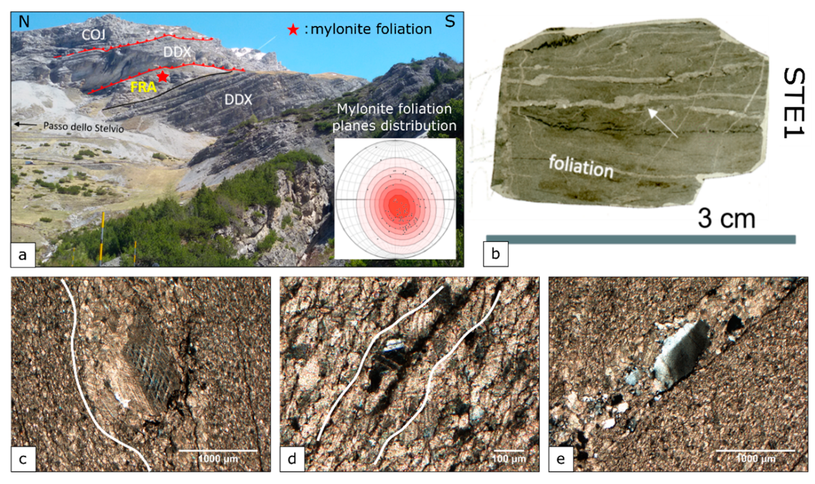
The sample from the Austroalpine Domain (STE1 sample) was collected along a thick shear horizon developed within the carbonatic cover on the Ortler-Quattervals Nappe—now exposed in the Braulio Valley (Bormio-SO)—displaying strong mylonite fabric (Figure 2) [24]. In this area, the nappe stack structuration, which is typical of the axial sector of the Alpine chain, is clearly visible (Figure 2a), with mylonites developed along the tectonic contacts within the dolomitic limestones of the Fraele Formation (FRA). Their thermal conditions have been estimated to be between 200 and 300 °C, either by the Thermal Alteration Index (TAI) of pollen and spores in the rocks [25] or using metamorphic minerals [26,27].
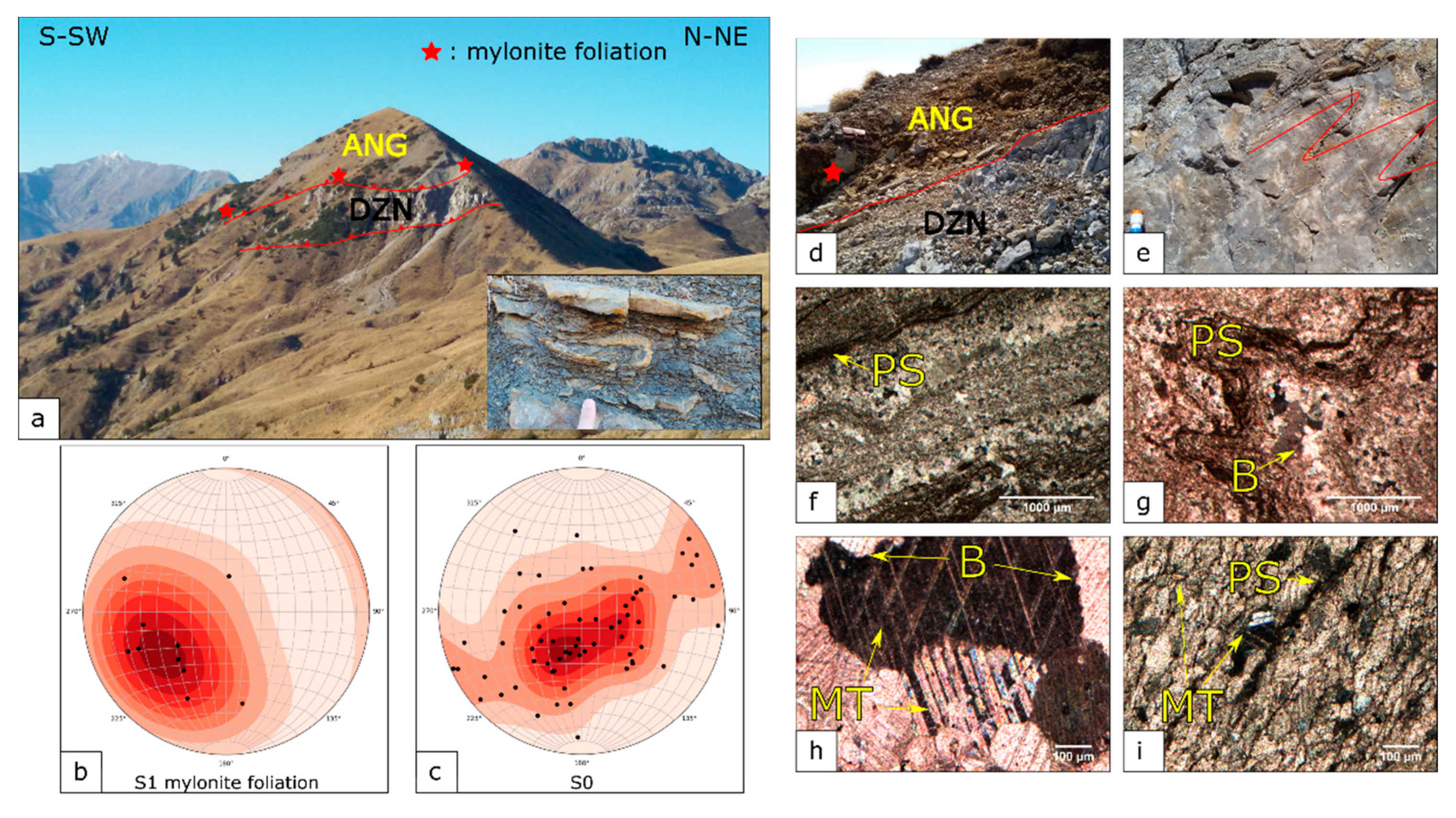
The Southern Alps Domain is characterized by thin- and thick-skinned tectonics that have produced km-scale thrust faults, mainly occurring within the shallow parts of the Permo-Mesozoic cover and its Paleozoic basement [28]. The three samples collected in the Southern Alps Domain (EP1, EP4, and EP7) were selected within one of the fault zones locally displaying a mylonite fabric [28] (Figure 3). In the Monte Sodadura area (Bergamo) (Figure 3), mylonite structures developed within the Calcare di Angolo Formation (ANG) and along the tectonic contacts with the underlying Dolomie Zonate Formation (DZN). They appear as strongly deformed portions in comparison with the surrounding rocks (Figure 3d,e). Based on geological observations [28,29], the temperatures can be constrained to 170–200 °C, at a depth not exceeding 10 km.
For the studied samples, further constraints of the deformation temperature were obtained using microstructural criteria that have previously been successfully tested in naturally deformed carbonatic rocks [30,31] (see Section 3.1).

2.2. Micro-Raman Spectroscopy

Micro-Raman spectroscopy was carried out using a Horiba LabRam HR Evolution spectrometer at the Dipartimento di Scienze della Terra “A. Desio” of the Università degli Studi di Milano (MI). The spectrometer was equipped with an Nd-Yag 532 nm/100 mW with Ultra Low Frequency (ULF) filters and a red laser source HeNe 633 nm/17 mW. Scattered light was collected by a 100× objective (NA aperture = 0.9) in backscattering geometry; a diffraction grating with 1800 L/mm and a hole of 200 μm were used. The spectrum was detected by a Peltier-cooled Charge Couple Detector. In order to avoid disordering induced by the laser source, the power was set at about 15 mW, as measured on the sample by a power-meter. To balance the signal and noise, two accumulations of 30 s were collected. Instrument calibration was performed before each round of analysis using the peak at 520.70 cm−1 of a silicon wafer. In the laboratory of Milan, most samples were collected using the 532 nm source. However, in order to test intra-laboratory and compare inter-laboratory results, a 632 nm source was also used to acquire, at the same acquisition conditions (1800 L/mm, hole of 200 μm, two accumulations for 60 s), the spectra of two samples: STE1 and EP7.
Analyses with a red laser source were carried out using a JobinYvon HR800 LabRam μ-spectrometer at room temperature, at the Department of Science and Technological Innovation (DiSIT) of the University of Eastern Piedmont (UPO). The instrument was equipped with an Olympus BX-41 Optical Microscope (OM), an HeNe 20 mW laser working at 632.8 nm, a grating of 1800 L/mm, and a charge-coupled device air-cooled detector. The hole was set at 200 μm. Before each analysis, the instrument calibration was verified by checking the position and intensity of the Si band at 520.65 ± 0.05 cm−1. To balance the signal against the noise, and at the same time to avoid changes in the structure of the carbon particles during the analysis, scans of at least four cycles of 30 s were performed, applying a D06 filter to the signal addressed to the sample.
All spectra were collected in the range of 900–1900 cm−1 in order to observe all the vibrational modes of the carbonaceous materials. Unpolished small blocks (about 4 × 2 cm and 0.5 cm thick) were obtained from the samples and 20 Raman spectra were collected from each of them from several different regions.
In addition to blocks, petrographic thin sections were prepared for both Optical Microscopy (OM) observations and micro-Raman spectroscopy. In particular, 10 Raman spectra were collected from each thin section.

2.3. Spectral Treatment

To evaluate the best baseline subtraction, different spectra fitting procedures and types of bands (i.e., Gaussian, Lorentzian, and Voigt) were applied. The most reliable parameters were obtained by performing a manual linear baseline subtraction and Lorentzian fitting [17]. Band fitting was performed by means of the Fityk software V. 0.9.8, as described in Lünsdorf et al. [17], using a script kindly granted by the author. To check the reliability of the automatic method using the Fityk software, band fitting was also performed in a manual way by means of OPUS software V. 5.5. In this study, based on the residual error calculated after different fitting procedures, five Lorentzian component bands, in agreement with the study of Kouketsu et al. [5], proved to be the best method and were therefore selected to analyze the experimentally recorded spectra. The fitted spectra were elaborated using ORIGIN software V. 6.0. The five obtained bands were labeled G, D1, D2, D3, and D4; their features will be discussed below.

3. Results

3.1. Microstructural Analysis and Related Temperature Estimates

3.1.1. STE1 Sample: Austroalpine Domain

STE1 is characterized by a highly strained carbonate grain aggregate that defines the matrix and few larger carbonate porphyroclasts, suggesting high strain conditions and temperatures (Figure 2). This is also supported by the twinning features [31,32,33] and the inferred deformation mechanisms [34]. Large porphyroclasts show twins characterized by tabular, curved, and lensoid shape patterns. The grain boundaries are highly irregular, and the porphyroclasts are characterized by sub-grain development. All of the above features strongly suggest active dynamic crystallization processes. The matrix aggregate exhibits a strong Shape Preferred Orientation (SPO) parallel to the foliation, and irregular to lobate grain boundaries. Grains in the matrix generally display a smaller density of twins when compared with the porphyroblasts (Figure 2), but signs of intracrystalline strain are visible, as undulose extinction and sub-grains (Table 1). According to the observed microstructures, a temperature of 300 °C can be inferred for the STE1 sample, in agreement with literature References [25,26,27].

3.1.2. EP1, EP4, and EP7 Samples: Southern Alps Domain

EP samples are characterized by a strong mm- to cm-thick layering, often folded at the meso-scale (Figure 3). At the microscopic scale, the layering is visible and generally marked by alternate coarse and fine grainsize layers (Figure 3f,g). Penetrative cleavage may also occur, most likely marked by opaque aggregates, often truncating large calcite grains (Figure 3f,g,i), and suggesting active pressure-solution processes (Table 1). Within calcite-rich layers, a bimodal distribution of grain-size is present: a matrix of small and equigranular carbonate grains, with little to no SPO and crystal-plastic microstructural features (Figure 3g,h and Table 1) wraps large grain-sized individuals. The latter are characterized by diffuse internal strain features as strain twinning (Figure 3h and Tables) with different thickness and patterns that range from thin twins to thick patchy, as described by Weber et al. [3]. These microstructural patterns can be used to infer strain states and temperatures of deformation [31,35]. Table 1 synthetically reports microstructures and deformation mechanisms recognized in the studied samples and the estimated temperatures. The resulting estimates fall in the range of 200–250 °C, in agreement with the available values in the literature, where a 175–250 °C interval is defined. These temperature estimates will be further discussed in comparison with micro-Raman data in the discussion paragraph.

3.2. Micro-Raman Spectroscopy on Carbonaceous Materials

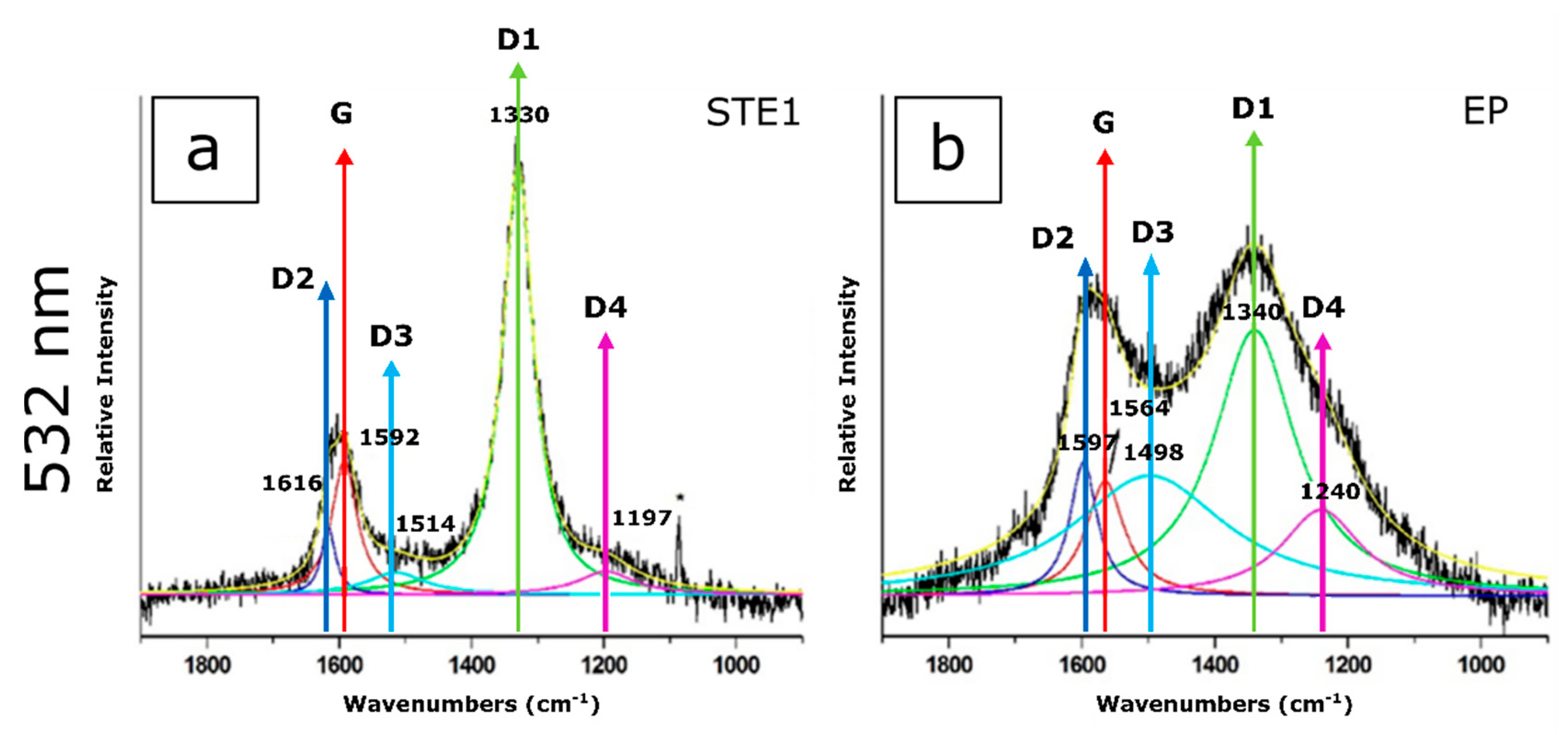
Figure 4 shows two representative Raman spectra of STE1 and EP samples collected with the 532 nm excitation source. The first order bands of carbonaceous materials are labeled as G (graphite-like), D1, D2, D3, and D4 (disorder) vibrational modes. The general behavior of EP CMs is similar in the three samples, so in the text, figures, and tables, their spectra will only be labeled as “EP”.
The G band, lying at around 1580 cm−1, is produced by doubly degenerated (LO and iTO) E2g phonons at the Brillouin zone center of the in-plane C-C stretching vibrations [5]. This band is the only one detectable on well-crystallized graphite, suggesting ordered CMs. The four bands (D1, D2, D3, and D4) are detected when the disorder in the carbonaceous material increases: The D1 band lies at about 1350 cm−1; D2 at about 1620 cm−1; D3 at about 1500 cm−1; and D4 at 1245 cm−1 [5]. The most representative patterns, obtained using both laser sources, are shown in Figure 5; the band frequencies obtained by Lorentzian deconvolution are reported in Table 2.
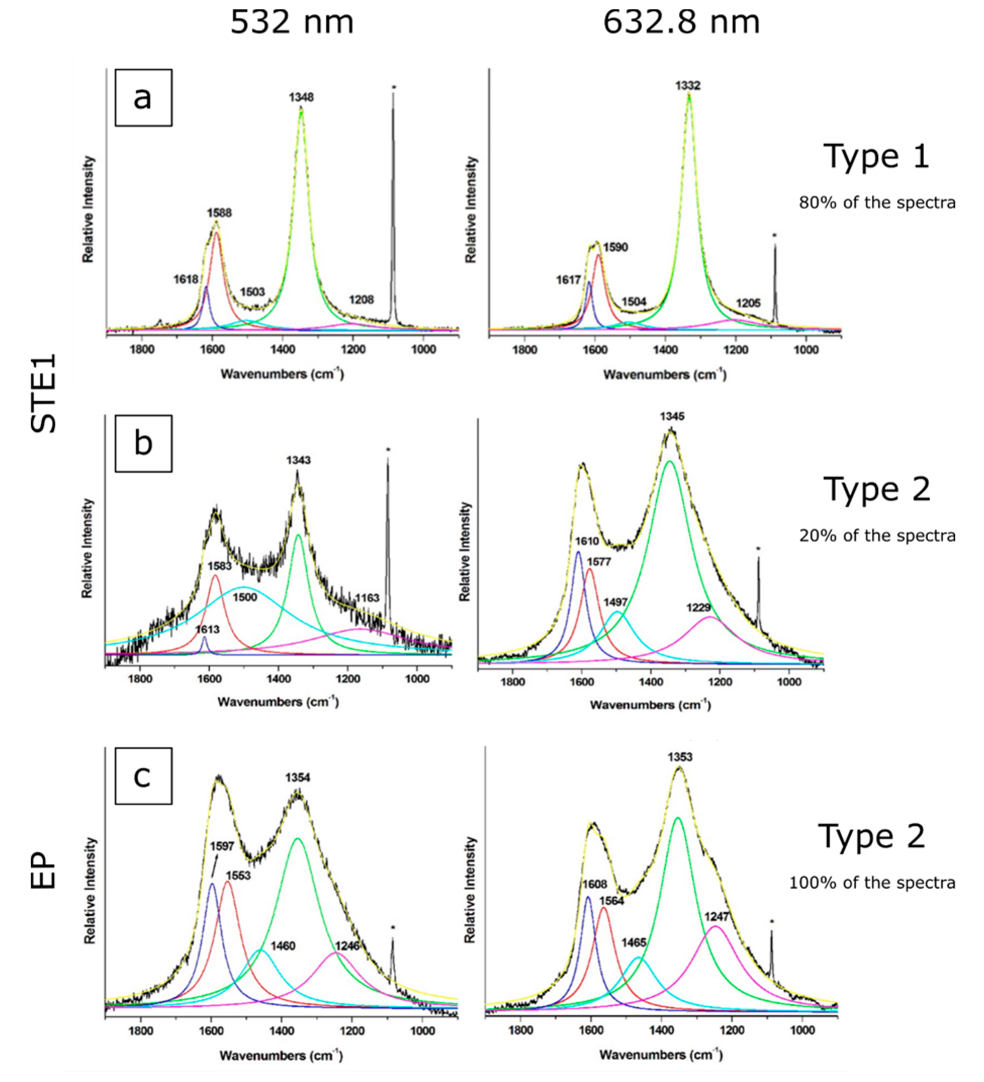
Although all samples show G, D1, D2, D3, and D4 bands in the 900–1900 cm−1 spectral region (Figure 5), two types of spectra have been recognized.
The STE1 sample generally shows Raman spectra with the D1 band being more intense than the G band (Type1, Figure 5a), with both 532 and 632.8 nm wavelengths. These spectra do not display fluorescence effects, and the D1 band at 1330–1350 cm−1 appears generally narrower and more intense with respect to the G band at ~1600 cm−1. STE1 shows, less frequently, a second type of pattern (Type 2, Figure 5b), characterized by less intense bands and a significant fluorescence effect. These features are more pronounced for the 632.8 nm laser source, but occur with both wavelengths (Figure 5b).
All of the EP samples, regardless of the laser source used, exhibit Type 2 patterns (Figure 5c) with a relevant fluorescence effect.
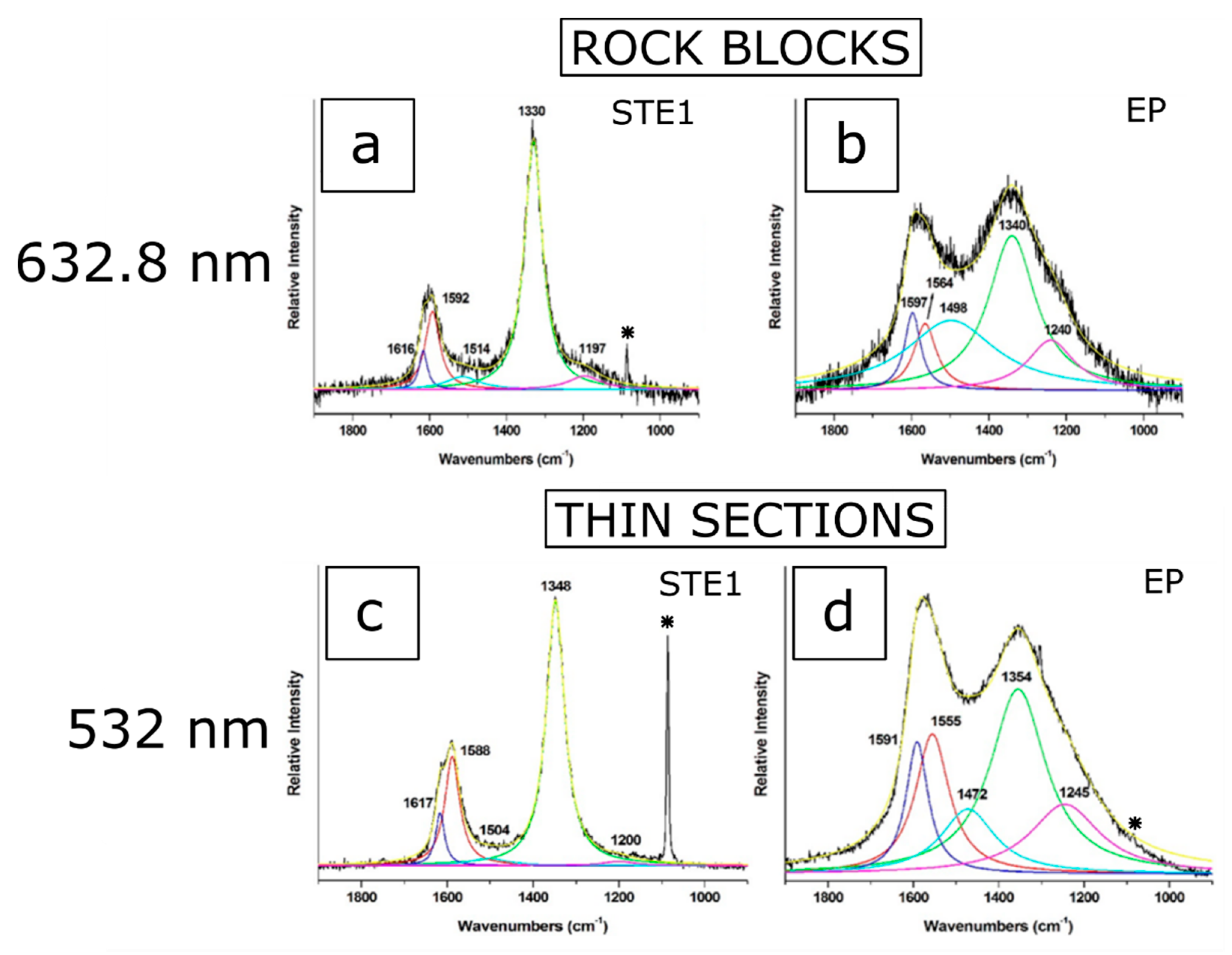
In order to rule out CM modifications, as a consequence of the cutting of the blocks and probably affecting the Raman signal, sets of analyses were performed on thin sections obtained from the same samples. In this case, CMs under translucent crystals were analyzed. The results are displayed in Figure 6.
The spectra in Figure 6 are reasonably close to those recorded for the rock blocks for both STE1 and EP samples and using both wavelengths as the excitation source. Consequently, an effect of the block preparation on the frequencies and intensities of the calculated bands is ruled out.

4. Discussion

4.1. Spectral Morphologies and Deconvolution

As expected from the theory of RSCM, the D1 band shows a shift, depending on the used excitation source: its wavenumber varies from 1348 to 1332 cm−1 when using the green and red laser, respectively. The other bands, detected by applying the fitting program, lie very close to both sources: the G band at about 1590 cm−1; D2 band at about 1620 cm−1; D3 band at about 1500 cm−1; and D4 band, which is less intense, at 1205 cm−1 (Figure 5a, Table 2). The difference between the spectra acquired with the two laser sources lies in the intensities of the D1 and D2 bands, which are more intense in the spectra acquired with the red source (Figure 5).
Following the flowchart of Kouketsu et al. [5] based on spectral morphologies, the Type 1 spectra suggest, regardless of the laser source, a medium-grade transitional carbonaceous material, with appraisal of temperature formation at 340 ± 25 °C. The same flowchart [5] applied to the Type 2 pattern of STE1 indicates a higher disorder degree and therefore a temperature of 301 ± 30 °C.
Considering the EP samples, Type 2 spectra are always recorded using both 532 and 632.8 nm wavelengths (see Figure 4b, Figure 5c, and Figure 6b), with the D1 band being more intense than the G one. Moreover, the D3 band appears more intense; the D4 band is always noticeable before fitting; and the D1 band, especially in the spectra obtained with the red laser source (632.8 nm wavelength), shifts to higher wavenumbers with respect to the values for the spectra obtained from the STE1 sample. In fact, shifting of the D1 band to higher wavenumbers is related to a lower metamorphic temperature [5]. All these data indicate a less ordered CM structure, and when applying the flowchart [5], the appraised temperature is 233 ± 30 °C.

4.2. Geothermometry

Several equations can be used to estimate the temperature from band parameters obtained by Raman spectroscopy. The main differences among the methods depend on the band parameters considered for temperature estimations. Ratios based on areas have been analyzed by Beyssac et al. and Sparkes et al.; band ratios based on intensities have been used by other researchers (e.g., Rahl et al.), and the FWHM of D1 or D2 bands, as in Kouketsu et al. [1,5,10,18].We will compare five different methods for defining the reliability of the used equations to obtain the data from the experimental setups used in this work:
  • The equation proposed by Beyssac et al. [1], where the R2 parameter (R2 = D1/(G + D1 + D2) band areas) is considered;
  • The procedure in Rahl et al. [18] (considering the same R1 and R2 parameters as in Beyssac et al. [1], and where R1 = D1/G peak intensities);
  • The parameters proposed by Sparkes et al. [10] (the RA2 parameter, where RA2 = (D1 + D4)/(G + D2 + D3 peak areas);
  • The approach described in Kouketsu et al. [5], where T (°C) = −6.78 × (FWHM − D2) + 535 (for 200 °C < T < 400 °C);
  • The other approach proposed by Kouketsu et al. [5], where T (°C) = −2.15 × (FWHM − D1) + 478 (for 150 °C < T < 200 °C).

4.2.1. STE1 Sample

As shown above, the two different laser sources produce comparable Raman signals. In this section, the results obtained by applying the different equations from the literature listed above will be discussed.
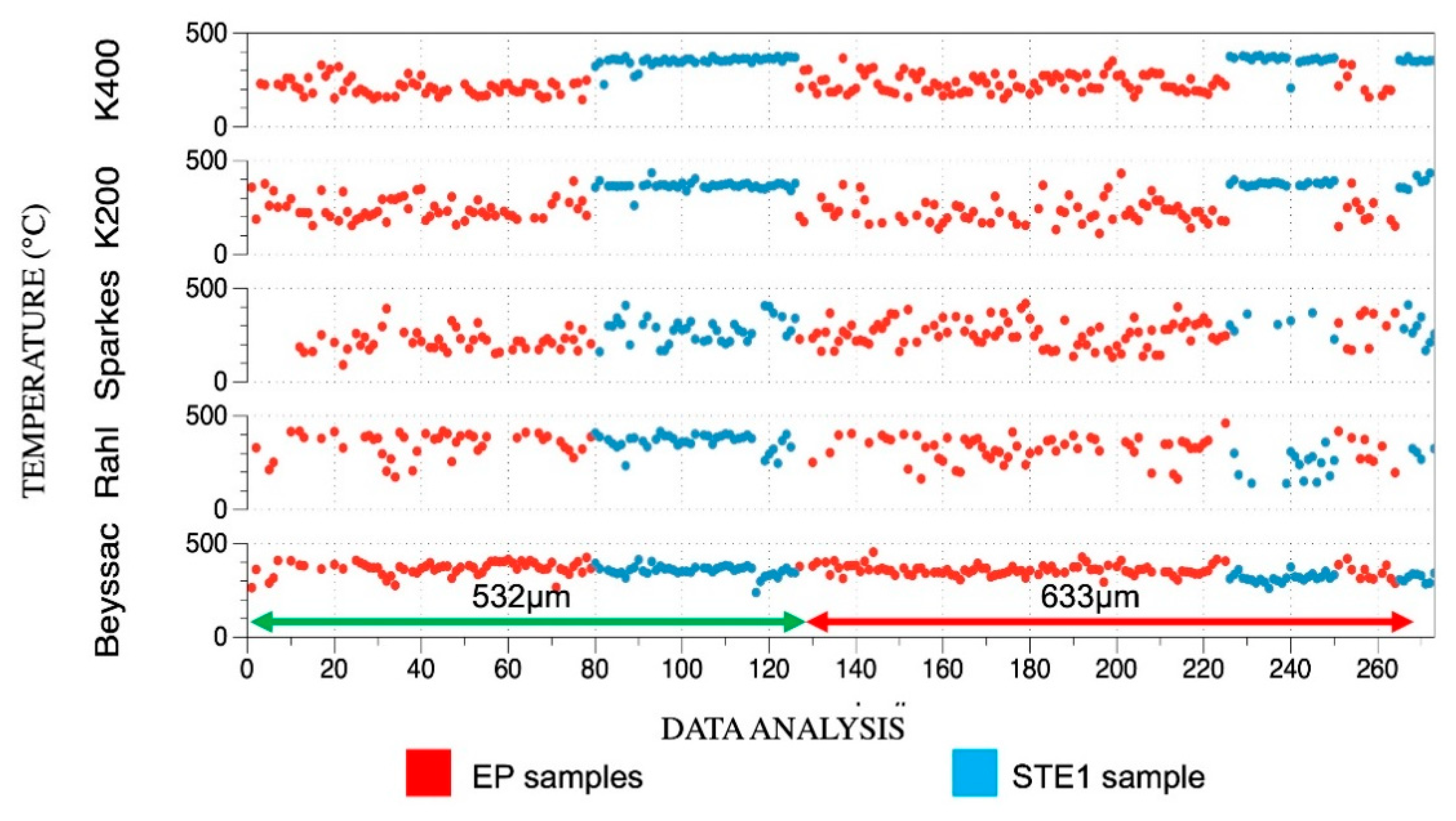
The temperatures obtained when applying the different equations are reported in Figure 7.
At first, the equation proposed by Beyssac et al. [1], where the R2 parameter (R2 = D1/(G + D1 + D2) band areas) is applied on the STE1 block sample, indicates a mean temperature of 362 ± 21 °C with a 532 nm laser source and 317 ± 24 °C with a 632.8 nm wavelength. It is worth noting that the data obtained from CMs included in translucent minerals, collected in a thin section using a 532 nm laser source, suggest 362 ± 10 °C—further indicating no modifications due to sample preparation.
The equations proposed by Rahl et al. and Sparkes et al. were tested [10,18], but the obtained temperature showed a high level of variability and the deduced temperatures, using both wavelengths, were not reliable (see Figure 7). These equations were proven not to be applicable.
Lastly, the equations proposed by Kouketsu et al. [5] were applied: Following the authors, the FWHM of D1 and D2 bands is independent on the experimental conditions (e.g., acquisition times, laser wavelength, and laser power on the sample). Applying the equation proposed for 200 °C < T < 400 °C
T (°C) = −2.15 × (FWHM − D1) + 478,
temperature formation for the STE1 sample revealed values of 339 ± 33 °C and 348 ± 56 °C when using 532 and 632.8 nm wavelengths respectively.
From the calculated temperatures, the CM grains in STE1 may be classified as medium-grade, confirming the first calculation from the flowchart. In fact, Kouketsu et al. on the basis of spectral features, proposed low-grade CMs from 165 to 301 °C, medium-grade CMs from 301 to 443 °C, high-grade CMs from 443 to 655 °C, and finally well-crystallized graphite for temperatures > 655 °C [5]. When applying the equation proposed by Kouketsu et al. [5], the temperatures using the two laser sources were reasonably similar.

4.2.2. EP Samples

Equation (1) was also applied to EP samples, and following the flowchart from Kouketsu et al. [5], a temperature of 233 ± 30 °C was suggested. It must be considered that for temperatures lower than 330 °C, the R2 ratio results are nearly constant at around 0.7–0.8. The applicability of the equation proposed by Beyssac et al. is therefore inappropriate for temperature estimations. For this reason, this geo-thermometer cannot be applied for the spectra from EP samples, where the low-grade CM order indicates temperatures lower than 330 °C [1].
Spectra from low-grade CMs were characterized by high fluorescence effects (Figure 4, Figure 5b,c, and Figure 6), affecting the band parameters used in the equations and resulting in very variable temperature appraisals [1,10,16,18], both using 532 and 632.8 nm laser wavelengths.
When applying the equation proposed by Kouketsu et al. [5] to EP samples, the temperature values, from treatment of the data obtained with the green laser source, resulted in values of 220 ± 65 °C for EP1, 189 ± 48 °C for EP4, and 195 ± 28 °C for EP7. When using a 632.8 nm wavelength as the excitation source, the obtained temperatures were 236 ± 56 °C for EP1, 217 ± 46 °C for EP4, and 238 ± 44 °C for EP7. With the two lasers, the obtained values always indicated low-grade CMs.
In addition, data from thin sections suggested a similar value (187 ± 48 °C) for the EP7 sample when using a 532 nm wavelength. The temperature data obtained by applying the different equations are schematically reported in Figure 7 and Table 3.
In sum, in medium-grade CMs, such as those in sample STE1, the fitting process of the Raman bands ascribed to CMs allowed an estimation of all the parameters, including the intensities, areas, and FWHM, confirming the temperatures obtained by petrographic analyses (temperatures > 200–250 °C, consistent with the temperatures obtained by the Raman geothermometer). In this case, it was possible to obtain reliable temperatures using both the equations from Beyssac et al. and Kouketsu et al. [1,5], considering Raman patterns from both 532 and 632.8 nm laser wavelengths.
In less ordered CMs, such as those characterizing EP samples, the situation appeared more complicated. In fact, fluorescence caused miscalculation in parameters, particularly in band areas and their intensities. For this reason, the results obtained from the application of the equations proposed by Beyssac et al., Rahl et al., and Sparkes et al., were characterized by a high level of variability and therefore prevented an estimation of the deformation temperatures [1,10,18] using both 532 and 632.8 nm laser wavelengths. In particular, the equation from Beyssac et al. overestimated the CM temperature (Figure 7) due to the incorrect band area evaluations after baseline subtraction.
In these cases, considering the FWHM of the D1 band, as proposed by Kouketsu et al. [5], the temperature estimations agree with both those obtained by petrographic analyses and the CM band morphologies considered in the flowchart. The results are comparable when using both green and red laser sources, and for EP samples, the peak temperatures resulted in a range of low-grade CMs. For these last samples, fluorescence effects may affect the geometries of the bands, since the curvature of the spectra modifies, after the application of the baseline, the ratios between intensities and areas of the components.
In Table 4, the means of R1, R2, and RA2 ratios and of FWHM-D1 and FWHM-D2 values and their standard deviations are reported.

4.2.3. Comparison of RSCM Temperatures with Microstructural Analyses

The microstructural analyses carried out on the same samples allowed us to obtain additional qualitative temperature estimations, on the basis of the deformation mechanisms active in the rocks. In fact, the contemporary presence of mechanical twinning lamellae in calcite grains [31,32,33] (Figure 2c and Figure 3h) and evidence of Grain Boundary Migration [35] (Figure 3g,h) made it possible to establish temperatures that were sufficiently high to cause plastic deformation of these rocks, and which were probably higher than 200–250 °C for all of the considered samples. This evidence is in agreement with the results obtained by micro-Raman spectroscopy and is also in agreement with the geological constraints.

4.2.4. Procedure

Considering the band elaboration procedure proposed by Lünsdorf et al. [17] and the flowchart and calculations by Kouketsu et al. [5]:
  • It has been demonstrated that reliable temperatures were obtained from the spectra recorded using the two sources of 532 and 632.8 nm;
  • It must be highlighted that it is necessary to understand the best acquisition conditions (i.e., laser power, recording time, and instrumental settings) to obtain data not affected by sample modifications or spectra not suitable for band fitting, giving incorrect parameters and, as a consequence, T estimations;
  • Baseline mode selection (e.g., linear and polynomial) is another step that can easily affect fitted band parameters, such as the FWHM, when the spectra display high fluorescence effects. All the spectra of this work were corrected through a linear baseline in the spectral range of 1000–1750 cm−1, in order to avoid, as much as possible, the subjectivity in this step of the elaboration [5,17].
In the fitted spectra of this work, FWHM-D1 appeared the most reliable parameter, whereas band areas and intensities were more affected by acquisition conditions.

5. Conclusions

The aim of this work was to carry out CM analyses, using micro-Raman spectroscopy, for an evaluation of the peak temperature in carbonate rocks, where a temperature lower than 330 °C is expected. In this work, the CM order/disorder degree was determined through tests in different laboratories and using two different wavelength laser sources: 532 nm, as used in many of the literature works, and 632.8 nm, in order to compare the obtained results.
In sum, the deformation temperatures were in the range of 340–350 °C in the STE sample and in the range of 200–240 °C in EP samples, independent of the excitation source of 532 or 632.8 nm. With this last source, corresponding to a higher wavelength, the heat on the specimen was reduced and this might be very important for avoiding structural changes in the analyzed samples.

Author Contributions

Conceptualization, M.Z., C.R., and A.C.; methodology, A.C. and E.P.; software, A.C., E.P., and M.Z.; validation, C.R., M.Z., and P.F.; formal analysis, A.C. and E.P.; investigation, A.C. and E.P.; resources, C.R., M.Z., and P.F.; data curation, A.C., E.P., and M.Z.; writing—original draft preparation, A.C., M.Z., C.R., E.P., and P.F.; writing—review and editing, A.C., M.Z., C.R., E.P., and P.F.; visualization, A.C., M.Z., C.R., E.P., and P.F.; supervision, M.Z. and C.R.; project administration, M.Z. and C.R. All authors have read and agreed to the published version of the manuscript.

Funding

Italian Ministry of Education, Universities and Research (MIUR)—Excellent Departments Project.

Acknowledgments

The authors thank Lünsdorf for his kind assistance in spectra elaboration and for the script applied for band fitting with Fityk software used in this work. M.Z. and P.F. acknowledge the support of the Italian Ministry of Education (MIUR) through the projects of Dipartimenti di Eccellenza 2018–2022. Two anonymous reviewers are kindly thanked for their help in improving the final form of the manuscript.

Conflicts of Interest

The authors declare no conflict of interest.

References

  1. Beyssac, O.; Goffé, B.; Chopin, C.; Rouzaud, J.N. Raman spectra of carbonaceous material in metasediments: A new geothermometer. J. Metamorph. Geol. 2002, 20, 859–871. [Google Scholar] [CrossRef]
  2. Croce, A.; Arrais, A.; Rinaudo, C. Raman Micro-Spectroscopy Identifies Carbonaceous Particles Lying on the Surface of Crocidolite, Amosite, and Chrysotile Fibers. Minerals 2018, 8, 249. [Google Scholar] [CrossRef] [Green Version]
  3. Henry, D.G.; Jarvis, I.; Gillmore, G.; Stephenson, M.; Emmings, J.F. Assessing low-maturity organic matter in shales using Raman spectroscopy: Effects of sample preparation and operating procedure. Int. J. Coal Geol. 2018, 191, 135–151. [Google Scholar] [CrossRef]
  4. Jehlička, J.; Beny, C. First and second order Raman spectra of natural highly carbonified organic compounds from metamorphic rocks. J. Mol. Struct. 1999, 480, 541–545. [Google Scholar] [CrossRef]
  5. Kouketsu, Y.; Mizukami, T.; Mori, H.; Endo, S.; Aoya, M.; Hara, H.; Nakamura, D.; Wallis, S. A new approach to develop the Raman carbonaceous material geothermometer for low-grade metamorphism using peak width. Isl. Arc 2014, 23, 33–50. [Google Scholar] [CrossRef]
  6. Marshall, C.P.; Love, G.D.; Snape, C.E.; Hill, A.C.; Allwood, A.C.; Walter, M.R.; Van Kranendonk, M.J.; Bowden, S.A.; Sylva, S.P.; Summons, R.E. Structural characterization of kerogen in 3.4Ga Archaean cherts from the Pilbara Craton, Western Australia. Precambrian Res. 2007, 155, 1–23. [Google Scholar] [CrossRef]
  7. Mirasol-Robert, A.; Grotheer, H.; Bourdet, J.; Suvorova, A.; Grice, K.; McCuaig, T.C.; Greenwood, P.F. Evidence and origin of different types of sedimentary organic matter from a Paleoproterozoic orogenic Au deposit. Precambrian Res. 2017, 299, 319–338. [Google Scholar] [CrossRef] [Green Version]
  8. Rinaudo, C.; Croce, A. Micro-Raman Spectroscopy, a Powerful Technique Allowing Sure Identification and Complete Characterization of Asbestiform Minerals. Appl. Sci. 2019, 9, 3092. [Google Scholar] [CrossRef] [Green Version]
  9. Sadezky, A.; Muckenhuber, H.; Grothe, H.; Niessner, R.; Pöschl, U. Raman microspectroscopy of soot and related carbonaceous materials: Spectral analysis and structural information. Carbon 2005, 43, 1731–1742. [Google Scholar] [CrossRef]
  10. Sparkes, R.; Hovius, N.; Galy, A.; Kumar, R.V.; Liu, J.T. Automated Analysis of Carbon in Powdered Geological and Environmental Samples by Raman Spectroscopy. Appl. Spectrosc. 2013, 67, 779–788. [Google Scholar] [CrossRef] [Green Version]
  11. Tuinstra, F.; Koenig, J.L. Raman Spectrum of Graphite. J. Chem. Phys. 1970, 53, 1126–1130. [Google Scholar] [CrossRef] [Green Version]
  12. Molli, G.; Vitale Brovarone, A.; Beyssac, O.; Cinquini, I. RSCM thermometry in the Alpi Apuane (NW Tuscany, Italy): New constraints for the metamorphic and tectonic history of the inner northern Apennines. J. Struct. Geol. 2018, 113, 200–216. [Google Scholar] [CrossRef] [Green Version]
  13. Lagabrielle, Y.; Clerc, C.; Vauchez, A.; Lahfid, A.; Labaume, P.; Azambre, B.; Fourcade, S.; Dautria, J.-M. Very high geothermal gradient during mantle exhumation recorded in mylonitic marbles and carbonate breccias from a Mesozoic Pyrenean palaeomargin (Lherz area, North Pyrenean Zone, France). Comptes Rendus Geosci. 2016, 348, 290–300. [Google Scholar] [CrossRef] [Green Version]
  14. Manzotti, P.; Rubatto, D.; Darling, J.; Zucali, M.; Cenki-Tok, B.; Engi, M. From Permo-Triassic lithospheric thinning to Jurassic rifting at the Adriatic margin: Petrological and geochronological record in Valtournenche (Western Italian Alps). Lithos 2012, 146, 276–292. [Google Scholar] [CrossRef]
  15. Henry, D.G.; Jarvis, I.; Gillmore, G.; Stephenson, M. A rapid method for determining organic matter maturity using Raman spectroscopy: Application to Carboniferous organic-rich mudstones and coals. Int. J. Coal Geol. 2019, 203, 87–98. [Google Scholar] [CrossRef]
  16. Lahfid, A.; Beyssac, O.; Deville, E.; Negro, F.; Chopin, C.; Goffé, B. Evolution of the Raman spectrum of carbonaceous material in low-grade metasediments of the Glarus Alps (Switzerland). Terra Nova 2010, 22, 354–360. [Google Scholar] [CrossRef]
  17. Lünsdorf, N.K.; Dunkl, I.; Schmidt, B.C.; Rantitsch, G.; Eynatten, H. von Towards a Higher Comparability of Geothermometric Data obtained by Raman Spectroscopy of Carbonaceous Material. Part I: Evaluation of Biasing Factors. Geostand. Geoanalytical Res. 2014, 38, 73–94. [Google Scholar] [CrossRef]
  18. Rahl, J.M.; Anderson, K.M.; Brandon, M.T.; Fassoulas, C. Raman spectroscopic carbonaceous material thermometry of low-grade metamorphic rocks: Calibration and application to tectonic exhumation in Crete, Greece. Earth Planet. Sci. Lett. 2005, 240, 339–354. [Google Scholar] [CrossRef]
  19. Sauerer, B.; Craddock, P.R.; AlJohani, M.D.; Alsamadony, K.L.; Abdallah, W. Fast and accurate shale maturity determination by Raman spectroscopy measurement with minimal sample preparation. Int. J. Coal Geol. 2017, 173, 150–157. [Google Scholar] [CrossRef]
  20. Lünsdorf, N.K.; Dunkl, I.; Schmidt, B.C.; Rantitsch, G.; Eynatten, H. von Towards a Higher Comparability of Geothermometric Data Obtained by Raman Spectroscopy of Carbonaceous Material. Part 2: A Revised Geothermometer. Geostand. Geoanalytical Res. 2017, 41, 593–612. [Google Scholar] [CrossRef]
  21. Koeppel, V.; Guenthert, A.; Gruenenfelder, M. Patterns of U-Pb zircon and monazite ages in polymetamorphic units of the Swiss Central Alps. Schweiz. Mineral. Petrogr. Mitteilungen 1981, 61, 97–119. [Google Scholar]
  22. Bernoulli, D.; Heitzmann, P.; Zingg, A. Central and southern Alps in southern Switzerland: Tectonic evolution and first results of reflection seismics. Mémoires Société Géologique France 1990, 156, 289–302. [Google Scholar]
  23. Frisch, W.; Ménot, R.-P.; Neubauer, F.; von Raumer, J.F. Correlation and evolution of the Alpine basement. Schweiz. Mineral. Petrogr. Mitt. 1990, 70, 265–285. [Google Scholar]
  24. Montrasio, A.; Berra, F.; Ceriani, M.; Deichmann, N.; Gregnanin, A.; Guerra, S.; Gugliemin, M.; Jadoul, F.; Longhin, M.; Mair, V.; et al. Note illustrative della Carta Geologica d’Italia alla scala 1:50.000—Foglio 24 Bormio. In APAT- Servizio Geologico d’Italia; Land and Technology Service: Padova e Treviso, Italy, 2012; p. 152. [Google Scholar]
  25. Berra, F.; Cirilli, S. Preservation and thermal alteration of organic matter in the Ortles and Quattervals nappes (Upper Austroalpine, Nord-Eastern Lombardy, Italy): Preliminary results and implications for regional geology. Eclogae Geol. Helv. 1997, 90, 325–336. [Google Scholar]
  26. Conti, P.; Manatschal, G.; Pfister, M. Synrift sedimentation, Jurassic and Alpine tectonics in the central Ortler nappe (Eastern Alps, Italy). Eclogae Geol. Helv. 1994, 87, 63–90. [Google Scholar]
  27. Conti, P. La falda Austroalpina dell’Ortles e l’evoluzione tettonica delle Dolomiti dell’Engadina (Svizzera-Italia) (con 17 tavole). Mem. Descr. Carta Geol. d’It. 1997, 53, 104. [Google Scholar]
  28. Gaetani, M.; Sciunnach, D.; Bini, A.; Rossi, S. Note Illustrative della Carta Geologica d’Italia alla scala 1:50.000—Foglio 76 Lecco. In APAT- Servizio Geologico d’Italia; Land and Technology Service: Padova e Treviso, Italy, 2010; p. 216. [Google Scholar]
  29. Viganò, A.; Tumiati, S.; Recchia, S.; Martin, S.; Marelli, M.; Rigon, R. Carbonate pseudotachylytes: Evidence for seismic faulting along carbonate faults. Terra Nova 2011, 23, 187–194. [Google Scholar] [CrossRef]
  30. Weber, J.C.; Ferrill, D.A.; Roden-Tice, M.K. Calcite and quartz microstructural geothermometry of low-grade metasedimentary rocks, Northern Range, Trinidad. J. Struct. Geol. 2001, 23, 93–112. [Google Scholar] [CrossRef]
  31. Ferrill, D.A.; Morris, A.P.; Evans, M.A.; Burkhard, M.; Groshong, R.H.; Onasch, C.M. Calcite twin morphology: A low-temperature deformation geothermometer. J. Struct. Geol. 2004, 26, 1521–1529. [Google Scholar] [CrossRef] [Green Version]
  32. Burkhard, M. Calcite twins, their geometry, appearance and significance as stress-strain markers and indicators of tectonic regime: A review. J. Struct. Geol. 1993, 15, 351–368. [Google Scholar] [CrossRef] [Green Version]
  33. Rybacki, E.; Evans, B.; Janssen, C.; Wirth, R.; Dresen, G. Influence of stress, temperature, and strain on calcite twins constrained by deformation experiments. Tectonophysics 2013, 601, 20–36. [Google Scholar] [CrossRef]
  34. Zucali, M.; Chateigner, D.; Ouladdiaf, B. Crystallographic and Seismic Anisotropies of Calcite at Different Depths: A Study Using Quantitative Texture Analysis by Neutron Diffraction. Minerals 2020, 10, 26. [Google Scholar] [CrossRef] [Green Version]
  35. Passchier, C.; Trouw, R. Microtectonics; Springer: Berlin/Heidelberg, Germany, 2005. [Google Scholar] [CrossRef]
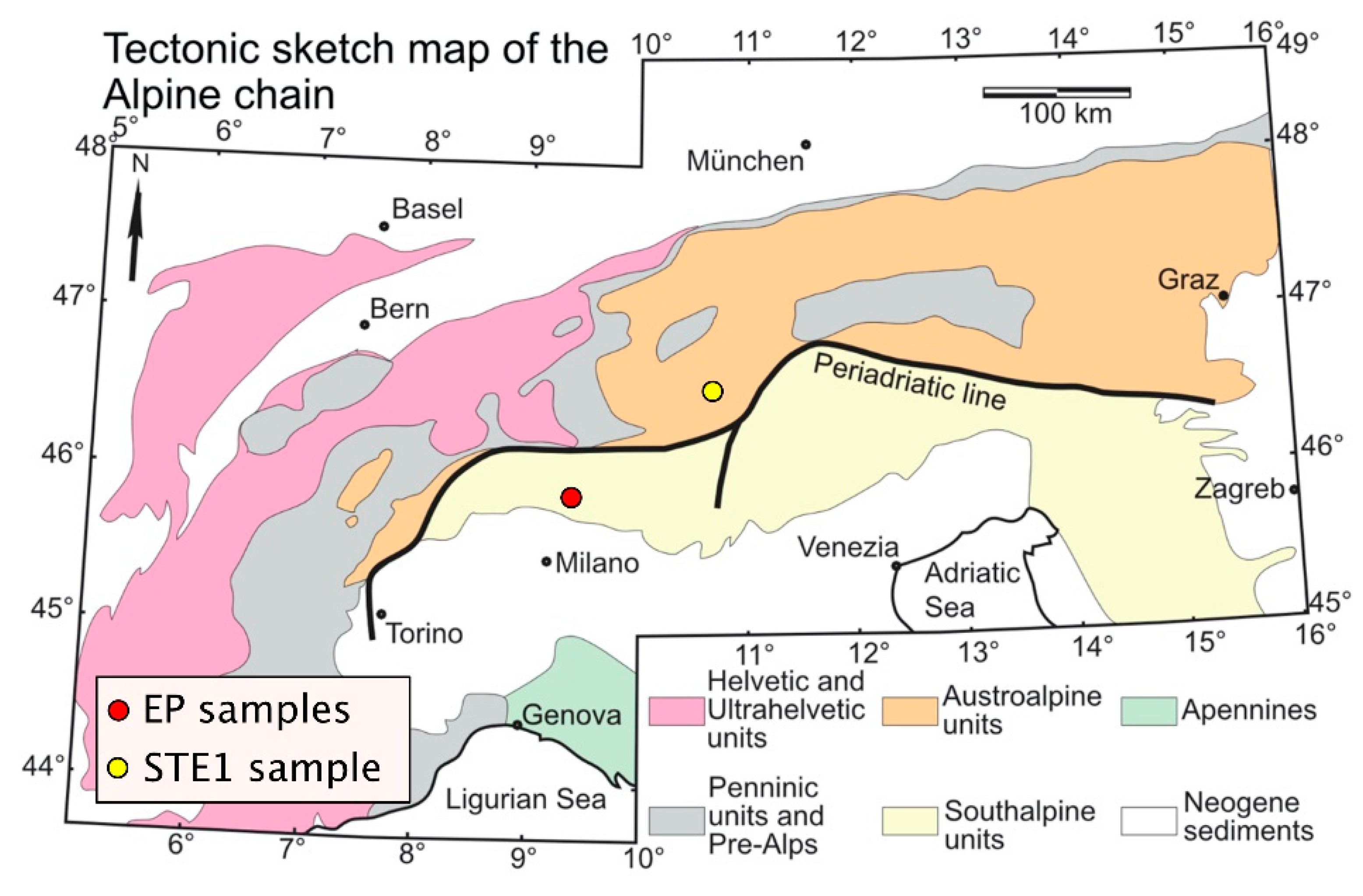
Figure 1. Tectonic map of the Alps showing the main geological domains and the locations where the analyzed samples were collected.
Minerals 10 01068 g001
Figure 2. Meso- and microstructural features of the Austroalpine cover in the Braulio Valley. (a) N–S geological section through the stratigraphic succession comprising orthogneisses (COJ), medium bedded dolomite (DDX), and mylonitic finely laminated dolomite (FRA). Samples were collected in the FRA interval, where a strong preferred orientation is shown by stereographic projections. (b) Hand specimen cut into thin sections clearly displays drag fold and strained layers (white parts). (ce) Microphotographs of the STE1 sample, showing the strong grain-size reduction that occurred during mylonite deformation. In c, large crystals are preserved within a fine-grained matrix that shows well-developed foliation.
Minerals 10 01068 g002
Figure 3. Meso- and microstructural features of the Southalpine Monte Sodadura carbonate mylonites. (a) NNE–SSW section of the Monte Sodadura showing the mylonitic horizons developed within the Calcare di Angolo Formation (ANG) where samples were collected. In the inset, an example of the plastic deformation that occurred within the carbonatic shales (ARS—Argillite di Riva di Solto Formation) underlying the tectonic contact with the Dolomie Zonate Formation (DZN) is shown. (b) Stereographic projections of the S1 mylonite foliation and (c) the S0 stratigraphic surfaces. (d,e) Mesoscopic feature of the mylonite horizon showing folds and syn-deformational foliation. (fi) Micro-scale images of the carbonate mylonite displaying different types of deformational microstructures and mechanisms (PS: pressure solution; B: bulging; and MT: mechanical twinning).
Minerals 10 01068 g003
Figure 4. Typical Raman fitting results obtained by the green laser source for (a) STE1 and (b) EP samples. The first order bands of carbonaceous materials are labeled as G (graphite-like), D1, D2, D3, and D4 (disorder) vibrational modes. The Raman band indicated by the * is ascribed to calcite (CaCO3), which is the main component of the rock.
Minerals 10 01068 g004
Figure 5. Typical spectrum types for STE1 and EP samples for 532 and 632.8 nm wavelength sources. Type 1 (a) vs. Type 2 (b,c). The D1 band lies at ~1340 cm−1, G at ~1580 cm−1, D2 at ~1605 cm−1, D3 at ~1460–1500 cm−1, and D4 at wavenumbers < 1250 cm−1. The Raman band indicated by the * is ascribed to calcite (CaCO3), which is the main component of the rock.
Minerals 10 01068 g005
Figure 6. 632 nm (a,b) vs. 532 nm (c,d) laser sources and rock block (a,b) vs. thin section (c,d). The Raman band indicated by the * is ascribed to calcite (CaCO3), which is the main component of the rock.
Minerals 10 01068 g006
Figure 7. Comparison of the temperature estimates for samples STE1 and EPs using the five equations applied in this work (K200 = from [5] for 150 °C < T < 200 °C, and K400 = from [5] for 200 °C < T < 400 °C).
Minerals 10 01068 g007
Table 1. Microstructural analysis results (Cc: calcite; Dol: dolomite; Qtz: quartz; Ox/H-Ox: oxi/hydroxides; cl: clay minerals; PS: pressure solution; B: bulging recrystallization; MT: mechanical twinning; and SGR: sub-grain rotation).
SampleLithologyFormationMineralsDeformation MechanismGrain DimensionMineral DistributionEstimated Temperatures
EP1LimestoneCalcare di Angolo (ANG)Cc, Ox/H-Ox, cl, ±DolPS, MT, B, SGRMin: 0.01 mm Max: 0.79 mmOx/H-Ox concentrated in levels; Cc max dimension in fold hinges and single grains within the fine-grained matrix>200 °C
EP4LimestoneCalcare di Angolo (ANG)Cc, Ox/H-Ox, cl, ±DolPS, MT, B, SGRMin: 0.01 mm Max: 0.68 mmOx/H-Ox concentrated in levels and dispersed; Cc max dimension concentrated in levels>200 °C
EP7LimestoneCalcare di Angolo (ANG)Cc, Ox/H-Ox, cl, ±DolPS, MT, B, SGRMin: 0.01 mm Max: 1.57 mmOx/H-Ox concentrated in levels; Cc max dimension in clusters within the fine-grained matrix>200 °C
STE1LimestoneFraele (FRA)Cc, Ox/H-Ox, cl, ±QtzPS, MT, B, SGRMin: 0.01 m Max: 1.25 mmOx/H-Ox concentrated in levels; Cc max dimension in clusters within the fine-grained matrix and in veins>200 °C
Table 2. Peak positions for STE1 and EP samples using 532 and 632.8 nm laser sources.
D4 (cm−1)D1 (cm−1)D3 (cm−1)G (cm−1)D2 (cm−1)Source (nm)SamplePattern
12081348150315881618532STE1Type1
12051332150415901617632.8STE1Type1
11631343150015831613532STE1Type2
12291345149715771610632.8STE1Type2
12461354146015631597532EPType2
12471353146515641608632.8EPType2
Table 3. Mean temperatures estimated with the five equations for STE1 and EP samples.
SampleMethodT (°C) Beyssac et al. [1]T (°C) Rahl et al. [18]T (°C) Sparkes et al. [10]T (°C) Kouketsu et al., 2014 [5]T (°C) Kouketsu et al., 2014 [5]
STE1532 nm block375395227339337
532 nm section348302361362367
632.8 nm block UPO317133463349358
633 nm block MI316195305354398
EP1532 nm block407408150199217
532 nm section397418176196218
632.8 nm block UPO391419240239152
EP4532 nm block358329234189257
632.8 nm block UPO359293284218157
EP7532 nm block387421184195174
532 nm section365361252187219
632.8 nm block UPO376341247239209
633 nm block MI334295254157150
Table 4. Mean values and standard deviations of the parameters used for temperature estimations by the five equations employed in this work.
R1 (D1/G Int)R2 (D1/(G + D1 + D2) Areas)RA2 ((D1 + D4)/(G + D2 + D3) Areas)FWHM-D1FWHM-D2
EP
532 nm
2.32 ± 0.870.60 ± 0.111.43 ± 0.48116 ± 2453 ± 17
EP
632.8 nm
1.58 ± 0.600.58 ± 0.101.17 ± 0.38135 ± 2450 ± 15
STE1
532 nm
3.13 ± 1.250.65 ± 0.131.98 ± 0.7667 ± 4427 ± 14
STE1
632.8 nm
2.04 ± 0.580.65 ± 0.061.53 ± 0.4160 ± 1526 ± 10
Publisher’s Note: MDPI stays neutral with regard to jurisdictional claims in published maps and institutional affiliations.