Assessing the Quality of Iron Ores for Bloomery Smelting: Laboratory Experiments


Abstract
:
1. Introduction
2. Materials and Methods
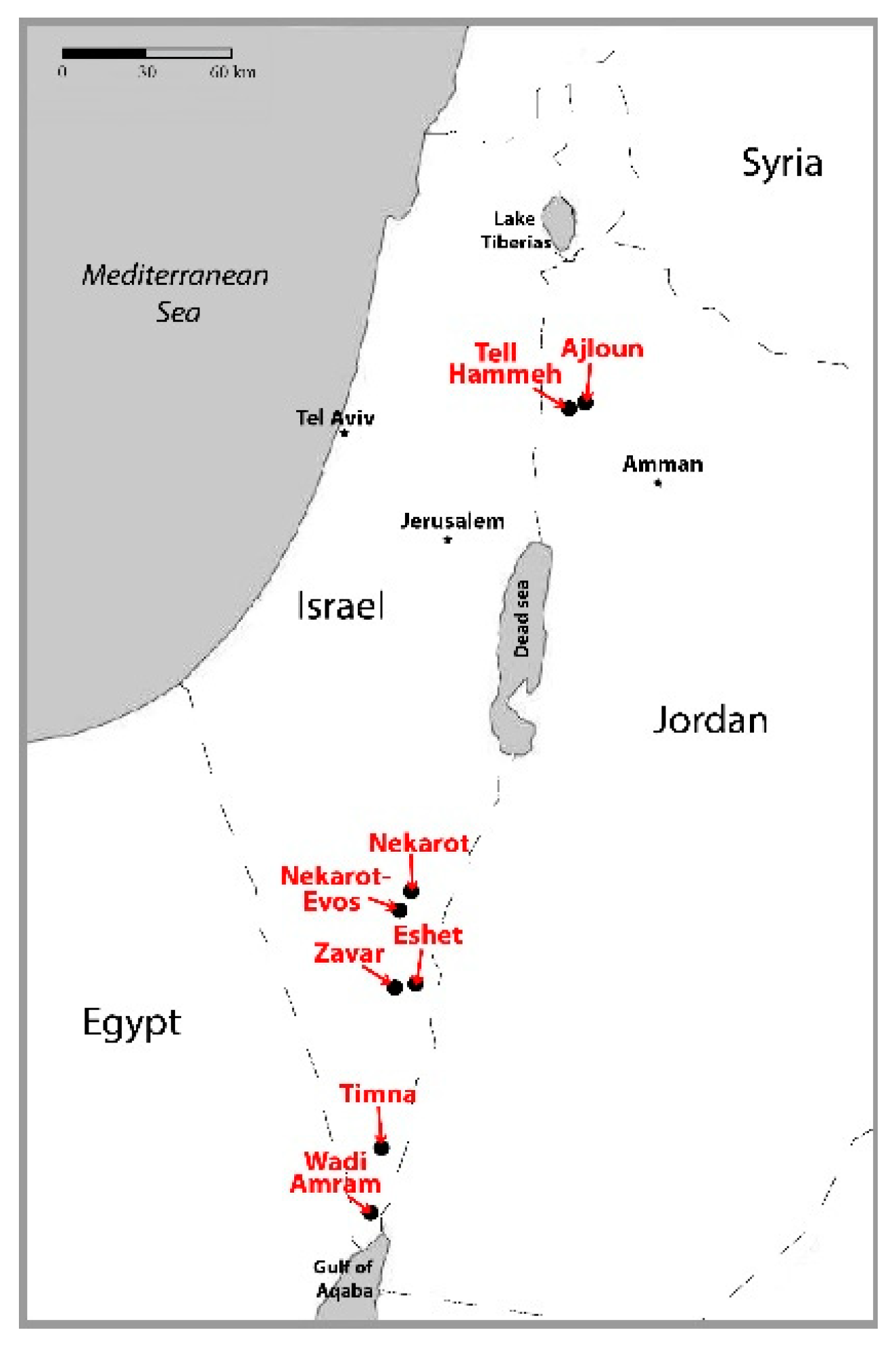
2.1. Iron Ores
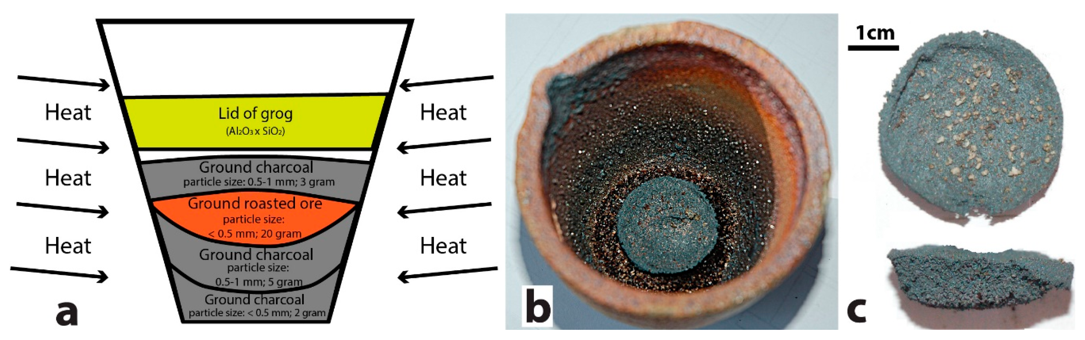
2.2. Assaying Setup
2.3. Characterization Methods
2.3.1. Portable X-Ray Fluorescence (pXRF)
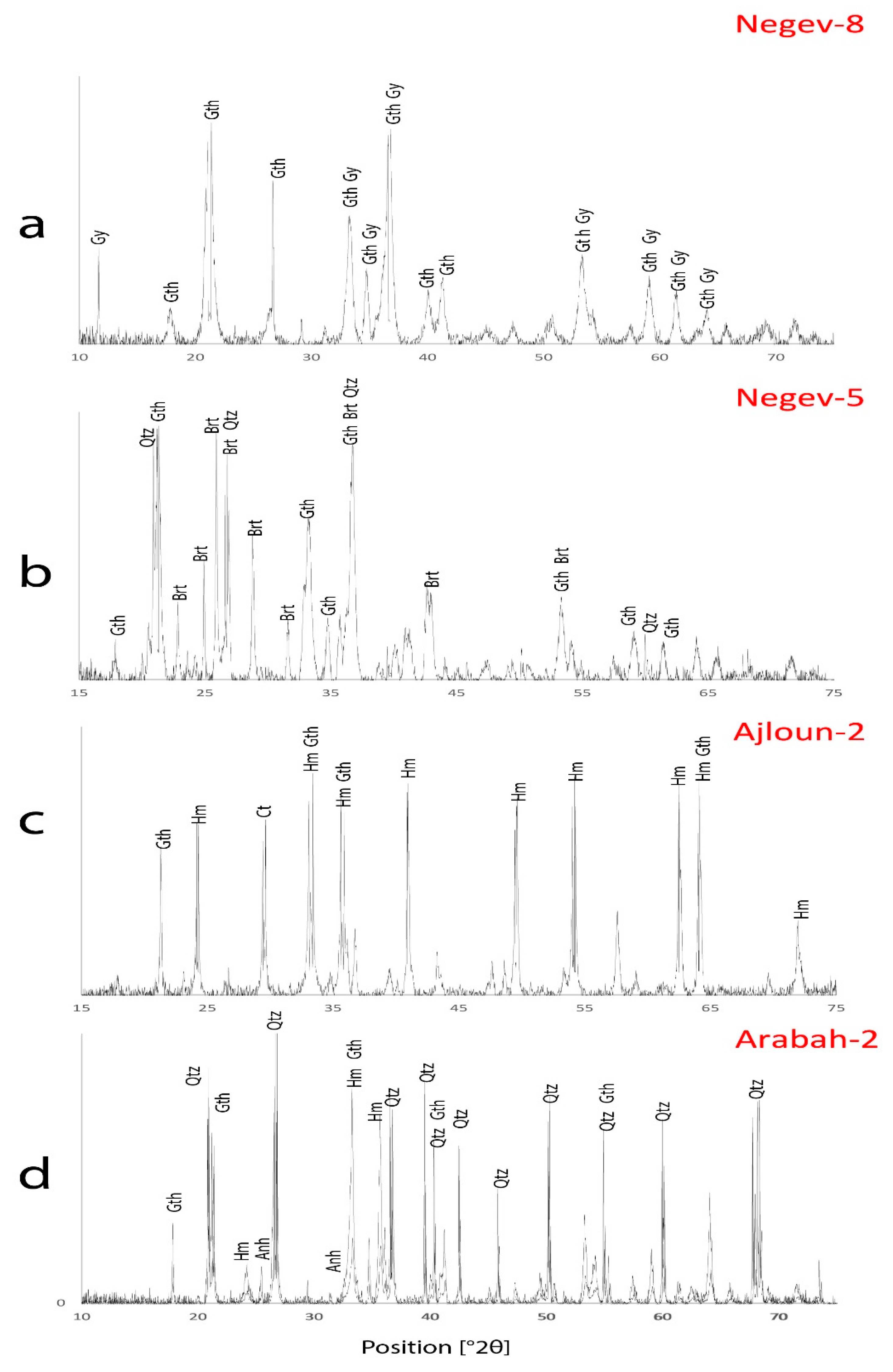
2.3.2. X-Ray Powder Diffraction (XRD)
2.3.3. Fourier Transforms Infrared Spectroscopy (FTIR)
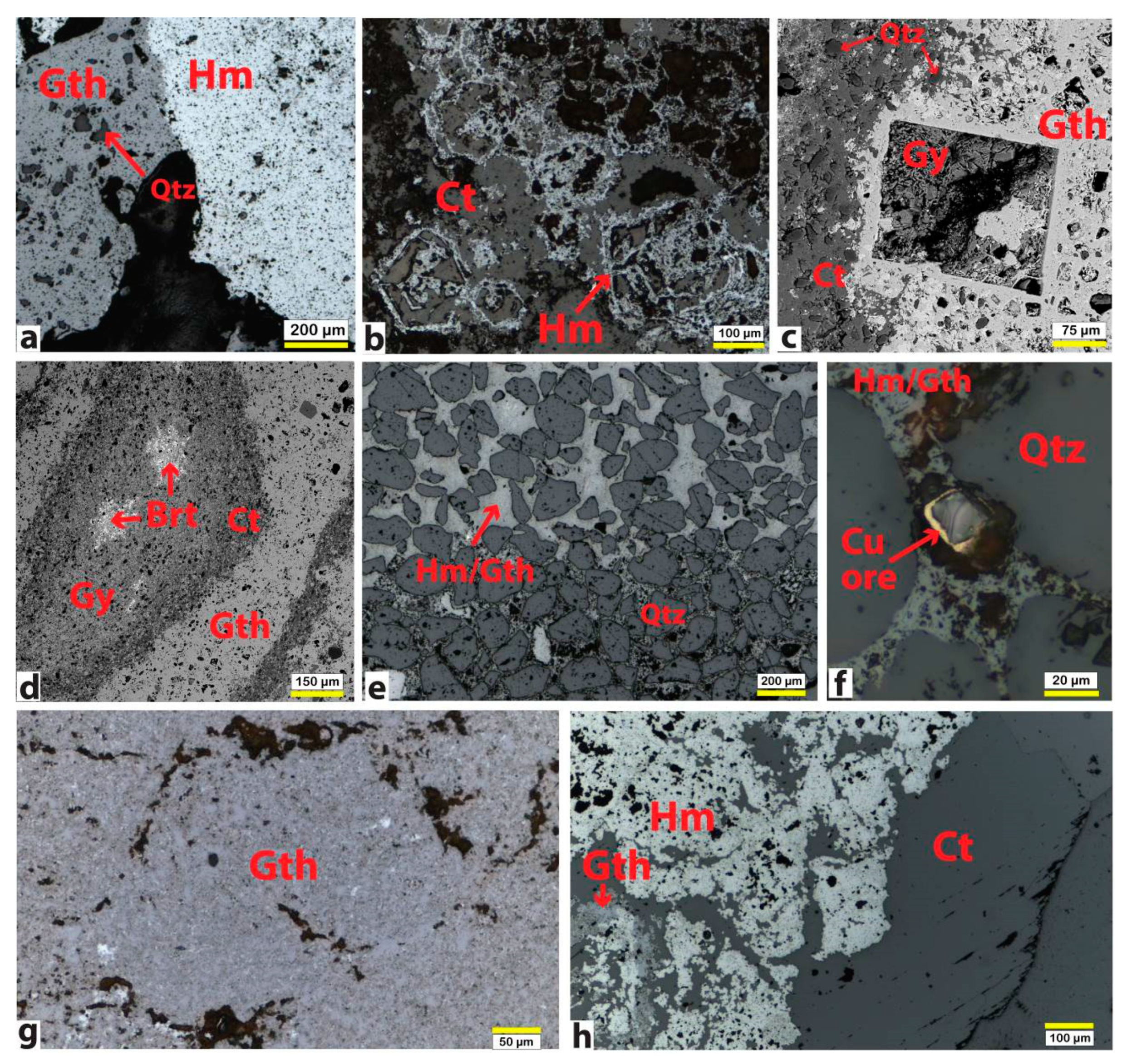
2.3.4. Optical and Electron Microscopy (OM and SEM-EDS)
3. Results
3.1. Characterization of Iron Ores
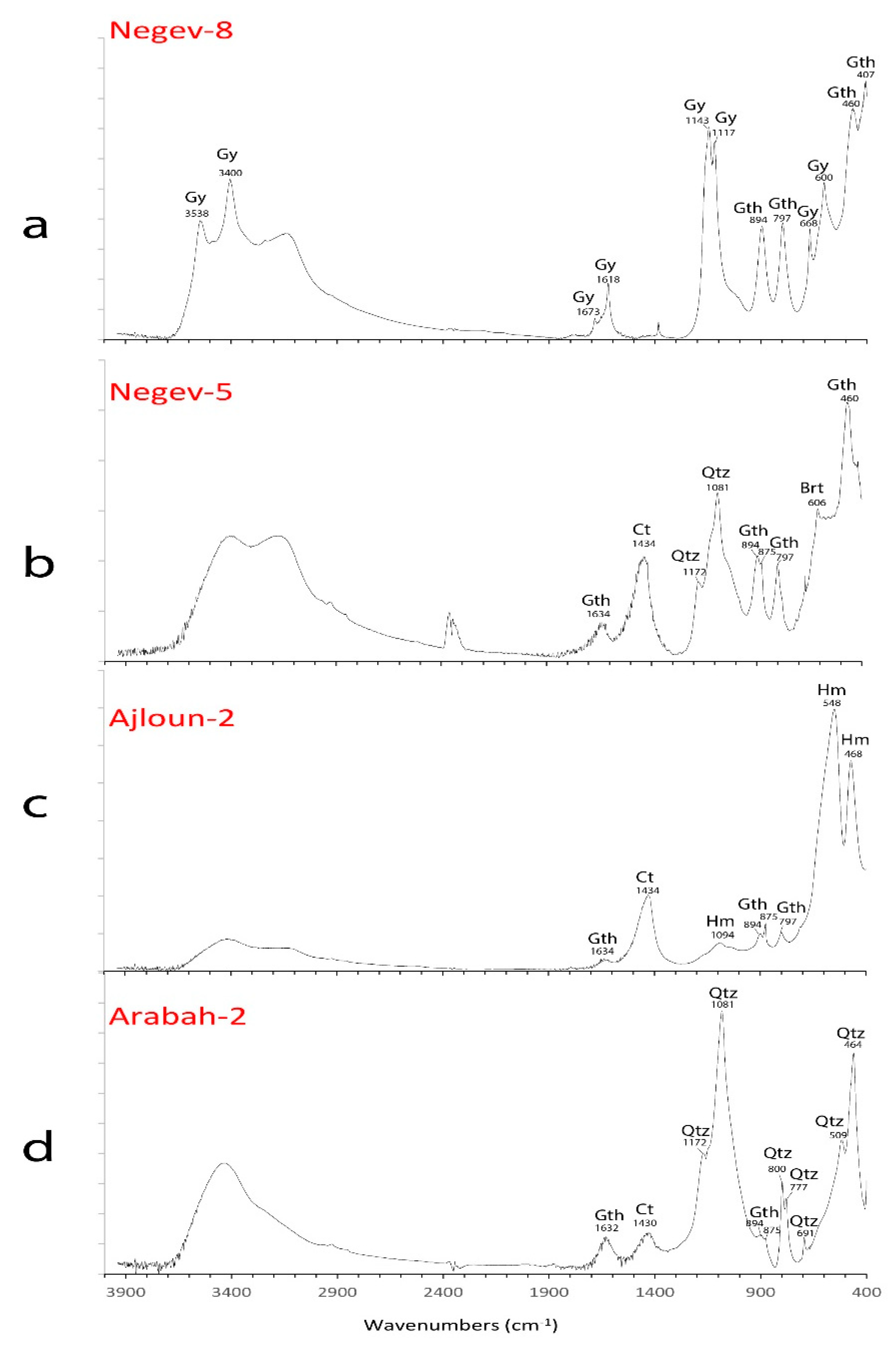
3.1.1. Negev Ores
3.1.2. Ajloun Ores
3.1.3. Arabah Ores
3.2. Characterization of Assaying Results
- Volume of reduced iron;
- Porosity of the bloom;
- Volume, composition, and mineralogy of the slag.
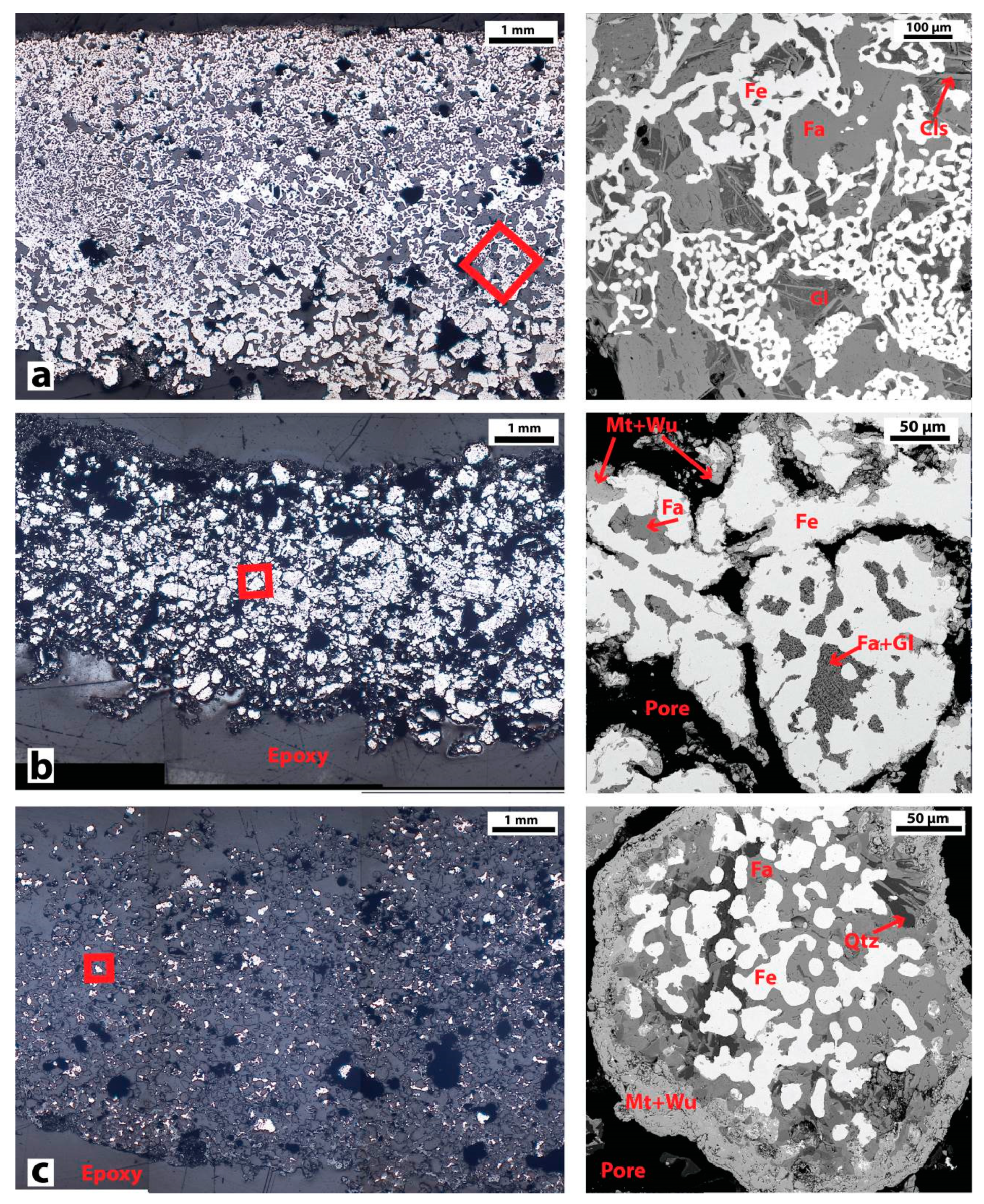
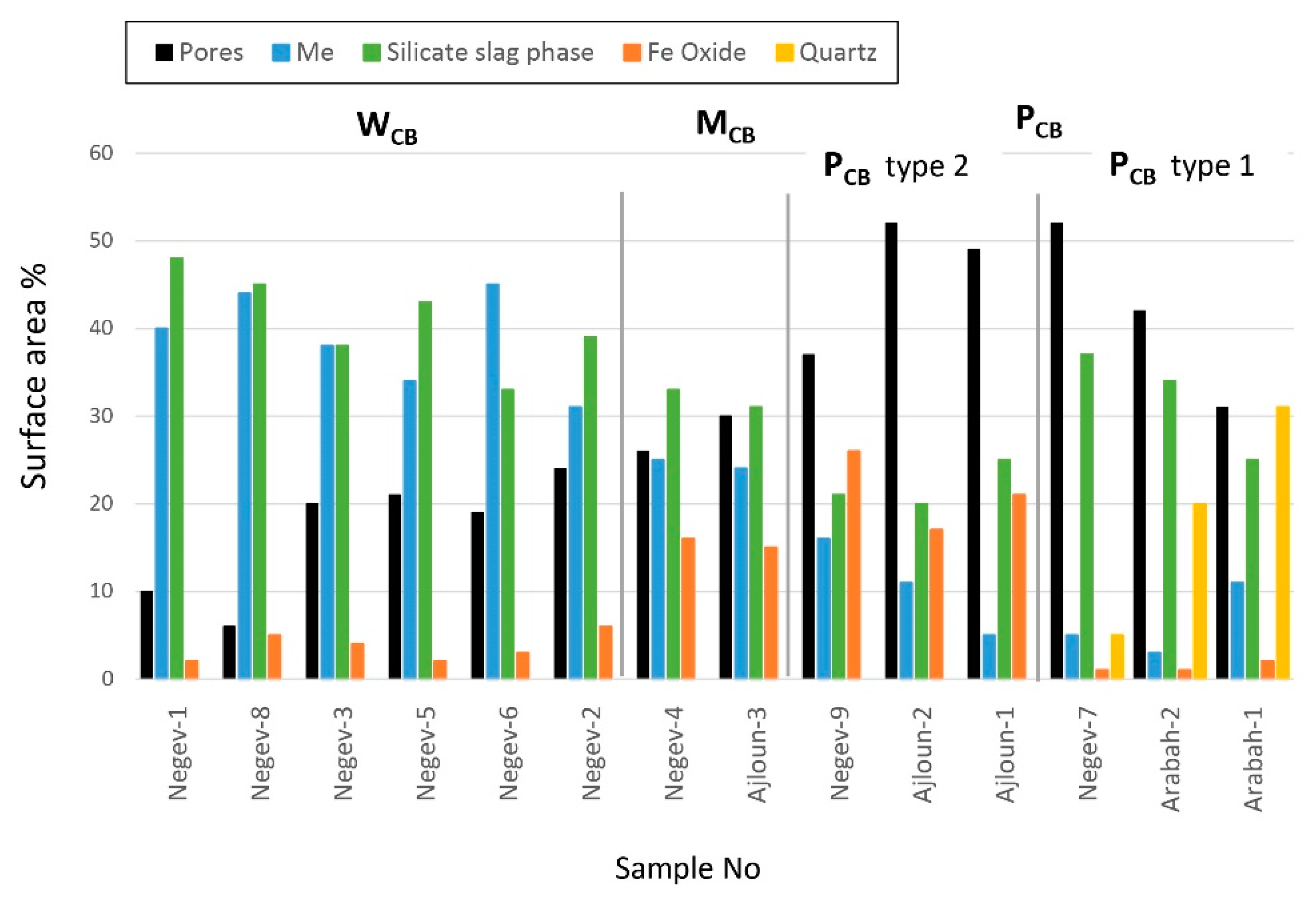
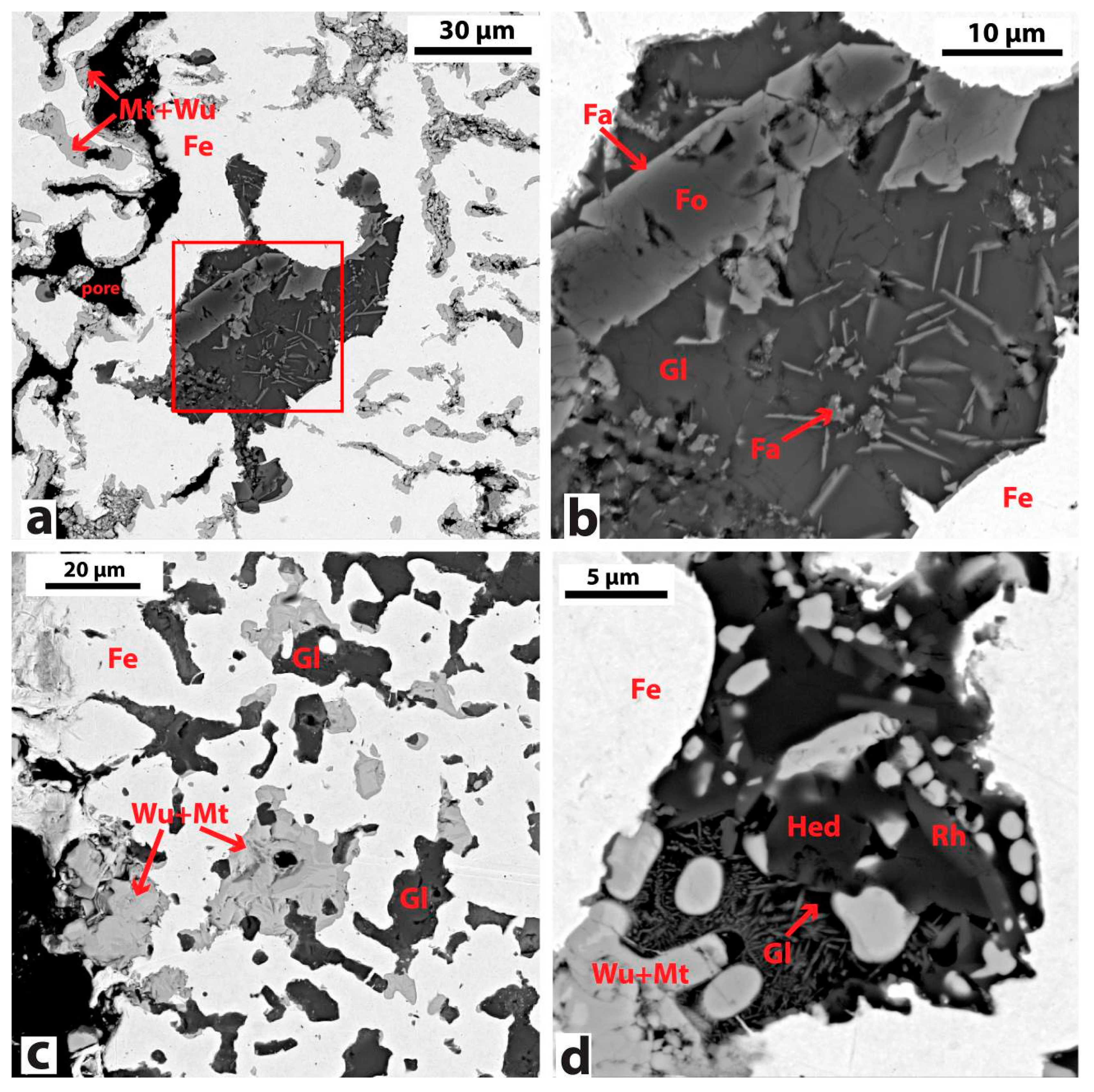
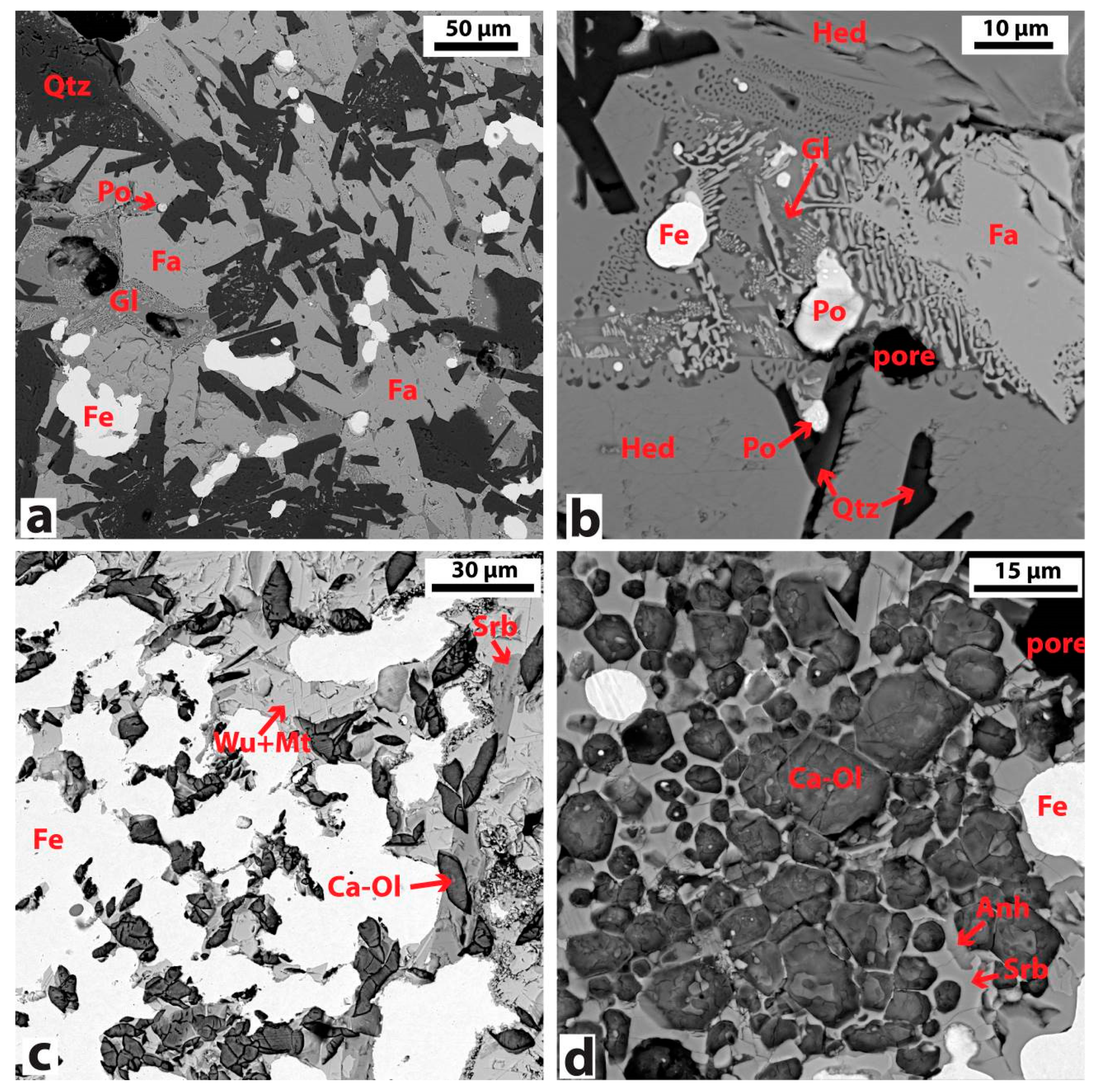
3.2.1. Bloom Consolidation
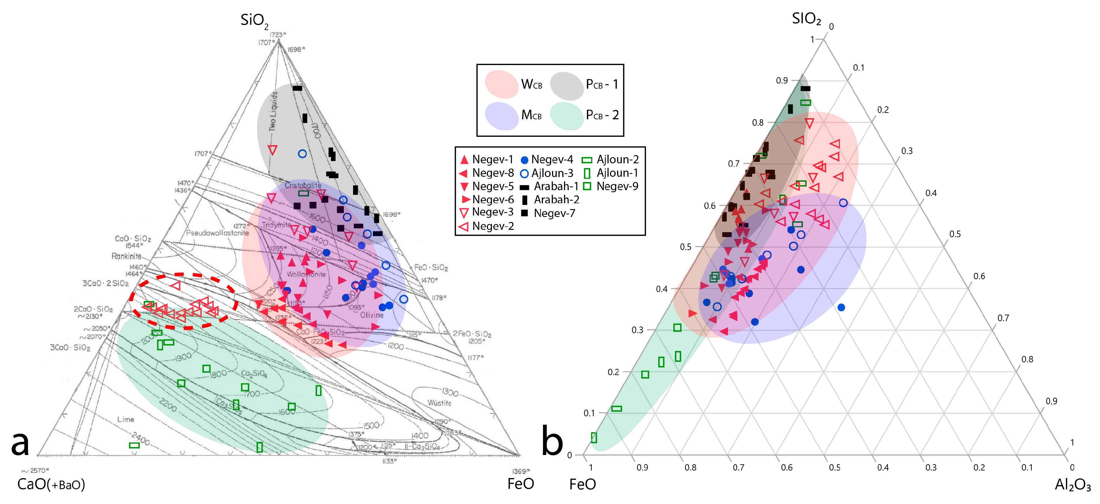
3.2.2. Chemical and Mineralogical Analysis of Slag
3.2.3. Effect of Sulphur and Copper on Iron
4. Discussion
5. Conclusions
Supplementary Materials
Author Contributions
Funding
Acknowledgments
Conflicts of Interest
References
- Eliyahu-Behar, A.; Yahalom-Mack, N.; Shilstein, S.; Zukerman, A.; Shafer-Elliott, C.; Maeir, A.M.; Boaretto, E.; Finkelstein, I.; Weiner, S. Iron and bronze production in Iron Age IIA Philistia: New evidence from Tell es-Safi/Gath, Israel. J. Archaeol. Sci. 2012, 39, 255–267. [Google Scholar] [CrossRef]
- Eliyahu-Behar, A.; Yahalom-Mack, N.; Gadot, Y.; Finkelstein, I. Iron smelting and smithing in major urban centers in Israel during the Iron Age. J. Archaeol. Sci. 2013, 40, 4319–4330. [Google Scholar] [CrossRef]
- Erb-Satullo, N.L.; Walton, J.T. Iron and copper production at Iron Age Ashkelon: Implications for the organization of Levantine metal production. J. Archaeol. Sci. Rep. 2017, 15, 8–19. [Google Scholar] [CrossRef]
- Erb-Satullo, N.L. The Innovation and Adoption of Iron in the Ancient Near East. J. Archaeol. Res. 2019, 27, 557–560. [Google Scholar] [CrossRef] [Green Version]
- Veldhuijzen, H.A.; Rehren, T. Slags and the city: Early iron production at Tell Hammeh, Jordan, and Tel Beth-Shemesh, Israel. In Metals and Mines: Studies in Archaeometallurgy; La Niece, S., Hook, D.R., Craddock, P., Eds.; Archetype, British Museum: London, UK, 2007; pp. 189–201. ISBN 9781904982197. [Google Scholar]
- Oliver, R.A.; Oliver, R.; Fagan, B.M. Africa in the Iron Age: C. 500 BC-1400 AD; Cambridge University Press: Cambridge, UK, 1975; ISBN 978-0521099004. [Google Scholar]
- Pleiner, R. Iron in Archaeology: The European Bloomery Smelters; Archeologický Ustav AV ČR: Prague, Czech Republic, 2000; ISBN 8086124266. [Google Scholar]
- Buchwald, V.F. Iron and Steel in Ancient Times; Kgl. Danske Videnskabernes Selskab: Copenhagen, Denmark, 2005; ISBN 978-8773043080. [Google Scholar]
- Rostoker, W.; Bronson, B. Pre-Industrial Iron: Its Technology and Ethnology; Archeomaterials: Filadelphia, PA, USA, 1990; ISBN 9780924171031. [Google Scholar]
- Rehren, T.; Charlton, M.; Chirikure, S.; Humphris, J.; Ige, A.; Veldhuijzen, H.A. Decisions set in slag: The human factor in African iron smelting. In Metals and Mines: Studies in Archaeometallurgy; La Niece, S., Hook, D.R., Craddock, P., Eds.; Archetype, British Museum: London, UK, 2007; pp. 211–218. ISBN 9781904982197. [Google Scholar]
- Iles, L.; Martinón-Torres, M. Pastoralist iron production on the Laikipia Plateau, Kenya: Wider implications for archaeometallurgical studies. J. Archaeol. Sci. 2009, 36, 2314–2326. [Google Scholar] [CrossRef]
- Killick, D.; Miller, D. Smelting of magnetite and magnetite–ilmenite iron ores in the northern Lowveld, South Africa, ca. 1000 CE to ca. 1880 CE. J. Archaeol. Sci. 2014, 43, 239–255. [Google Scholar] [CrossRef]
- Blakelock, E.; Martinon-Torres, M.; Veldhuijzen, H.A.; Young, T. Slag inclusions in iron objects and the quest for provenance: An experiment and a case study. J. Archaeol. Sci. 2009, 36, 1745–1757. [Google Scholar] [CrossRef]
- Charlton, M.; Humphris, J. Exploring ironmaking practices at Meroe, Sudan—A comparative analysis of archaeological and experimental data. Archaeol. Anthropol. Sci. 2019, 11, 895–912. [Google Scholar] [CrossRef]
- Senn, M.; Gfeller, U.; Guénette-Beck, B.; Lienemann, P.; Ulrich, A. Tools to qualify experiments with bloomery furnaces. Archaeometry 2010, 52, 131–145. [Google Scholar] [CrossRef] [Green Version]
- Thiele, A.; Dévényi, L. Modelling possibilities of the medieval bloomery process under laboratory conditions. Mater. Sci. Forum 2013, 729, 290–295. [Google Scholar] [CrossRef]
- Martinón-Torres, M.; Rehren, T. Alchemy, chemistry and metallurgy in Renaissance Europe: A wider context for fire-assay remains. Hist. Metall. 2015, 39, 14–28. [Google Scholar]
- Killick, D. Invention and innovation in African iron-smelting technologies. Camb. Archaeol. J. 2015, 25, 307–319. [Google Scholar] [CrossRef]
- Agricola, G. De Re Metallica; Hoover, H.C.; Hoover, L.H., Translators; Dover Publications: New York, NY, USA, 1950; ISBN 9780486600062. [Google Scholar]
- Ploquin, A.; Orzechowski, S.; Briand, B. Paléométallurgie à Mleiha: Une première approche. Travaux de la Maison de l’Orient méditerranéen. In Mleiha I. Environnement, Stratégies de subsistance et artisanats; Mouton, M., Ed.; Maison de l’Orient méditerranéen: Lyon, France, 1999; pp. 171–190. ISBN 2-903264-71-6. [Google Scholar]
- Stepanov, I. Ferrous Metal Production and Use at Saruq al-Hadid. Ph.D. Thesis, University of New England, Armidale, Australia, 2019. [Google Scholar]
- Kassianidou, V. Could Iron Have Been Produced in Cyprus? Department of Antiquities: Nicosia, Cyprus, 1994; pp. 73–81. [Google Scholar]
- Ilani, S.; Rosenthal, E.; Kronfeld, J.; Flexer, A. Epigenetic dolomitization and iron mineralization along faults and their possible relation to the paleohydrology of southern Israel. Appl. Geochem. 1988, 3, 487–498. [Google Scholar] [CrossRef]
- Al-Amri, Y.A.S. The Role of The Iron Ore Deposit of Mugharet El-Wardeh/Jordan in the Development of the Use of Iron in Southern Bilad El-Sham. Ph.D. Thesis, Bochum University, Bochum, Germany, 2008. [Google Scholar]
- Erel, Y.; Listovsky, N.; Matthews, A.; Ilani, S.; Avni, Y. Tracing end-member fluid sources in sub-surface iron mineralization and dolomitization along a proximal fault to the dead sea transform. Geochim. Cosmochim. Acta 2006, 70, 5552–5570. [Google Scholar] [CrossRef]
- Grosz, S.; Matthews, A.; Ilani, S.; Ayalon, A.; Garfunkel, Z. Iron mineralization and dolomitization in the Paran Fault zone, Israel: Implications for low-temperature basinal fluid processes near the Dead Sea Transform. Geofluids 2006, 6, 137–153. [Google Scholar] [CrossRef]
- Dill, H.G.; Botz, R.; Berner, Z.; Abdullah, M.; Hamad, A. The Origin of Pre-and Synrift, Hypogene Fe-P Mineralization during the Cenozoic along the Dead Sea Transform Fault, Northwest Jordan. Econ. Geol. 2010, 105, 1301–1319. [Google Scholar] [CrossRef]
- Al-Malabeh, A.; Kempe, S.; Henschel, H.-V.; Hofmann, H.; Tobschall, H.J. The possibly hypogene karstic iron ore deposit of Warda near Ajloun (Northern Jordan), its mineralogy, geochemistry and historic mine. Acta Carsologica 2008, 37, 241–253. [Google Scholar] [CrossRef] [Green Version]
- Hauptmann, A. The Archaeometallurgy of Copper: Evidence from Faynan, Jordan; Springer: Bochum, Germany, 2007; ISBN 978-3-540-72237-3. [Google Scholar]
- Xuejing, X.; Mingcai, Y.; Lianzhong, L.; Huijun, S. Usable Values for Chinese Standard Reference Samples of Stream Sediments, Soils, and Rocks: GSD 9-12, GSS 1-8 and GSR 1-6. Geostand. Newsl. 1985, 9, 277–280. [Google Scholar] [CrossRef]
- Certificate of Certified Reference Materials. NCS DC 73014—NCS DC73022; Stream Sediment: Beijing, China, 2010. [Google Scholar]
- Levin, E.M.; Robbins, C.R.; McMurdie, H.F. Phase Diagrams for Ceramists, 1st ed.; The American Ceramic Society Inc.: Columbus, OH, USA, 1964. [Google Scholar]
- Folkhard, E. Welding Metallurgy of Stainless Steels, 1st ed.; Springer Science: New York, NY, USA, 2012; ISBN 978-3-7091-8965-8. [Google Scholar]
- Park, J.-S.; Reichert, S. Technological tradition of the Mongol Empire as inferred from bloomery and cast iron objects excavated in Karakorum. J. Archaeol. Sci. 2015, 53, 49–60. [Google Scholar] [CrossRef]
- Paynter, S. Innovations in bloomery smelting in Iron Age and Romano-British England. Metals and mines. In Metals and Mines: Studies in Archaeometallurgy; La Niece, S., Hook, D.R., Craddock, P., Eds.; Archetype, British Museum: London, UK, 2007; pp. 202–210. ISBN 9781904982197. [Google Scholar]
- Mukhopadhyay, D.K.; Lindsley, D.H. Phase relations in the join kirschsteinite (CaFeSiO4)-fayalite (Fe2SiO4). Am. Mineral. 1983, 68, 1089–1094. [Google Scholar]
- Ströbele, F.; Wenzel, T.; Kronz, A.; Hildebrandt, L.H.; Markl, G. Mineralogical and geochemical characterization of high-medieval lead–silver smelting slags from Wiesloch near Heidelberg (Germany)—An approach to process reconstruction. Archaeol. Anthropol. Sci. 2010, 2, 191–215. [Google Scholar] [CrossRef] [Green Version]
- Kronz, A. Phasenbeziehungen und Kristallisationsmechanismen in fayalitischen Schmelzsystemen: Untersuchungen an Eisen-und Buntmetallschlacken; Klaus Bielefeld Verlag: Friedland, Germany, 1997; ISBN 3-932325-16-8. [Google Scholar]
- Crew, P. Twenty-five years of bloomery experiments: Perspectives and prospects, Accidental and Experimental Archaeometallurgy. In Accidental and Experimental Archaeometallurgy; Dungworth, D., Doonan, R., Eds.; Historical Metallurgical Society: London, UK, 2013; pp. 25–50. ISBN 978-0956022516. [Google Scholar]
- Deer, W.H.; Howie, R.A.; Zussman, J. An Introduction to Rock-Forming Minerals, 2nd ed.; Longman Scientific & Technical: Essex, UK; Willey: New York, NY, USA, 1992. [Google Scholar]
- Eekelers, K.; Degryse, P.; Muchez, P. Petrographic investigation of smithing slag of the Hellenistic to Byzantine city of Sagalassos (SW-Turkey). Am. Mineral. 2016, 101, 1072–1083. [Google Scholar] [CrossRef] [Green Version]
- Kucha, H.; Waelkens, M.; Viaene, W.; Laduron, D. Mineralogy, geochemistry and phase equilibria as tracers of the technology of iron (steel) making at Sagalassos during the Roman period. In Sagalassos III. Report on the Fourth Excavation Campaign of 1993; Waelkens, M., Poblome, J., Eds.; Leuven University Press: Leuven, Belgium, 1995; pp. 273–291. [Google Scholar]
- Leroy, M.; Le Carlier, C.; Merluzzo, P. Entre bas et haut fourneau. L’utilisation de la minette de Lorraine au Moyen Age: Une parfaite adéquation avec la technique du bas fourneau. In Proceedings of the Actes du 4è Congrès International d’Archéologie Médiévale et Moderne, Paris, France, 3–8 September 2007; INHA: Paris, France, 2007; pp. 1–18. [Google Scholar]
- Ben-Yosef, E.; Shaar, R.; Tauxe, L.; Ron, H. A new chronological framework for Iron Age copper production at Timna (Israel). Bull. Am. Sch. Orient. Res. 2012, 367, 31–71. [Google Scholar] [CrossRef]
- Avner, U.; Ginat, H.; Shalev, S.; Shilstine, S.; Langford, B.; Frumkin, A.; Shem-Tov, R.; Filin, S.; Arav, R.; Basson, U.; et al. Ancient copper mines at Nahal Amram, Southern Arabah. In Mining for Ancient Copper. Essays in Memory of Beno Rothenberg; Ben-Yosef, E., Ed.; Tel-Aviv University: Tel-Aviv, Israel, 2018; pp. 147–177. ISBN 978-1575069647. [Google Scholar]
- Piatak, N.M.; Parsons, M.B.; Seal, R.R., II. Characteristics and environmental aspects of slag: A review. Appl. Geochem. 2015, 57, 236–266. [Google Scholar] [CrossRef]
- Gee, C.; Ramsey, M.H.; Maskall, J.; Thornton, I. Mineralogy and weathering processes in historical smelting slags and their effect on the mobilisation of lead. J. Geochem. Explor. 1997, 58, 249–257. [Google Scholar] [CrossRef]
- Veldhuijzen, H. Early Iron Production in the Levant. Ph.D. Thesis, Institute of Archaeology, Unviersity College London, London, UK, 2005. [Google Scholar]
- Brauns, M.; Yahalom-Mack, N.; Stepanov, I.; Sauder, L.; Keen, J.; Eliyahu-Behar, A. Osmium Isotope Analysis as an Innovative Tool for Provenancing Ancient Iron: A Systematic Approach. PLoS ONE 2019. Accepted for publication. [Google Scholar]


| Sample No. | Sample Name | Deposit | Morphology | Main Mineralogical Phases by FTIR, XRD, OM/SEM | |||||
|---|---|---|---|---|---|---|---|---|---|
| Hm | Gth | Cal | Gy/Anh | Qtz | Brt | ||||
| 1 | Negev-1 | Nekarot-Evos | Black dense ore | +++ | tr | tr | + | tr | |
| 2 | Negev-2 | Nekarot-Evos | Black dense ore | +++ | + | tr | + | tr | |
| 3 | Negev-3 | Zavar | Black-brown dense ore with conchoidal fracture | + | +++ | tr | + | tr | |
| 4 | Negev-4 | Zavar | Black-brown dense ore | + | +++ | + | |||
| 5 | Negev-5 | Nekarot | Black dense ore | + | +++ | tr | tr | ++ | + |
| 6 | Negev-6 | Nekarot | Black dense ore | + | +++ | tr | tr | ++ | tr |
| 7 | Negev-7 | Nekarot | Rusty brown ore with black banding | + | +++ | + | ++ | ||
| 8 | Negev-8 | Eshet | Yellowish rusty ore | +++ | + | + | |||
| 9 | Negev-9 | Eshet | Brown rusty ore | ++ | ++ | ++ | + | ||
| 10 | Ajloun-1 | Warda | Reddish-brown rusty ore | ++ | + | ++ | + | ||
| 11 | Ajloun-2 | Warda | Black dense ore with white calcite veins | +++ | + | + | tr | ||
| 12 | Ajloun-3 | Warda | Brown dense ore with conchoidal fracture | +++ | tr | + | |||
| 13 | Arabah-1 | Wadi Amram | Iron nodule | + | + | tr | +++ | ||
| 14 | Arabah-2 | Timna | Iron nodule | + | + | tr | +++ | ||
| Amount of Roasted Ore, g. | Amount of Charcoal, g. | Ore Fraction for Roasting and Smelting | Charcoal Fraction for Smelting | Roasting, Temperature and Time | Smelting, Temperature and Time |
|---|---|---|---|---|---|
| 20 | 10 | <0.5 mm | 0.5–1 mm (8 g); dust < 0.5 mm (2 g) | 20–>600 °C (1 h); keep at 600 °C (2 h) | 20–>800 °C (1 h); 800–>1200 °C (1 h); 1200–>1250°C (1 h); keep at 1250 °C (1 h) |
| Total time: 3 h | Total time: 4 h |
| Sample No | MgO | Al2O3 | SIO2 | P2O5 | SO3 | K2O | CaO | TiO2 | V2O5 | MnO | FeO | BaO | Tot | Zr | Sr | Cu | Pb | As | Zn | Ni | |
|---|---|---|---|---|---|---|---|---|---|---|---|---|---|---|---|---|---|---|---|---|---|
| wt.% | ppm | ||||||||||||||||||||
| Negev-1 | 1.1 | 3.3 | 1 | 0.1 | 1.5 | 0.2 | 79.7 | 0.66 | 87.6 | 188 | 694 | 214 | 406 | ||||||||
| Negev-2 | 0.9 | 2.2 | 1.5 | 0.2 | 4.6 | 0.1 | 0.3 | 77.7 | 0.12 | 87.6 | 122 | 666 | 65 | 311 | 185 | ||||||
| Negev-3 | 3.1 | 0.9 | 5.7 | 0.9 | 0.1 | 0.5 | 0.1 | 80.1 | 0.17 | 91.6 | 106 | 781 | 89 | 46 | 524 | ||||||
| Negev-4 | 1.7 | 1 | 3.2 | 1.1 | 0.1 | 0.5 | 0.2 | 84.3 | 0.05 | 92.3 | 11 | 38 | 649 | 276 | 1174 | ||||||
| Negev-5 | 1.4 | 9 | 0.1 | 4.6 | 0.1 | 0.8 | 0.5 | 0.1 | 67.7 | 4.7 | 89.1 | 380 | 921 | 630 | 382 | ||||||
| Negev-6 | 1.8 | 8.8 | 0.2 | 1.1 | 0.2 | 2.5 | 0.1 | 0.7 | 73.8 | 0.68 | 90.0 | 21 | 114 | 826 | 782 | 252 | |||||
| Negev-7 | 0.7 | 30.6 | 0.1 | 0.4 | 0.1 | 6.1 | 0.2 | 47 | 0.23 | 85.5 | 11 | 125 | 592 | 32 | 346 | 291 | |||||
| Negev-8 | 1.9 | 1.4 | 4.6 | 0.1 | 2.9 | 0.2 | 1.3 | 0.1 | 0.1 | 0.1 | 75.2 | 88.0 | 20 | 73 | 706 | 387 | |||||
| Negev-9 | 1.2 | 1.6 | 1.4 | 0.2 | 12.1 | 0.3 | 67.4 | 0.04 | 84.3 | 13 | 128 | 718 | 363 | ||||||||
| Ajloun-1 | 0.7 | 1.7 | 0.4 | 0.1 | 16.1 | 0.1 | 0.1 | 56.5 | 75.7 | 16 | 36 | 668 | 235 | 53 | 159 | ||||||
| Ajloun-2 | 0.8 | 1.6 | 0.5 | 0.2 | 6 | 85.5 | 94.6 | 780 | 77 | 210 | 164 | ||||||||||
| Ajloun-3 | 1.8 | 0.8 | 0.6 | 0.3 | 0.1 | 0.1 | 88.4 | 92.1 | 707 | ||||||||||||
| Arabah-1 | 1.6 | 1.2 | 32.8 | 0.1 | 0.8 | 0.1 | 0.3 | 0.1 | 0.1 | 53.9 | 0.45 | 92.0 | 29 | 104 | 1188 | 1382 | 205 | 3492 | 433 | ||
| Arabah-2 | 1.4 | 0.7 | 38.4 | 3 | 0.1 | 1.1 | 0.2 | 42.9 | 87.9 | 265 | 40 | 404 | 18 | 67 | |||||||
| STD Iron Pl3.20 | Meas. value | 6.2 | 0.2 | 0.3 | 92.3 | 99.0 | 852 | 15 | 20 | ||||||||||||
| Cert. value | 5.3 | 0.1 | 0.1 | 96.9 | 102.4 | 15 | |||||||||||||||
| STD GSS-1 | Meas. value | 0.9 | 8.9 | 54.7 | 0.3 | 1.8 | 1.6 | 0.7 | 0.02 | 0.2 | 4.9 | 0.03 | 74.1 | 242 | 154 | 198 | 100 | 34 | 670 | 20 | |
| Cert. value | 1.8 | 14.2 | 62.5 | 0.2 | 2.6 | 1.7 | 0.8 | 0.02 | 0.2 | 4.7 | 0.07 | 88.9 | 241 | 135 | 22 | 91 | 33 | 552 | 26 | ||
| STD GBW07112 | Meas. value | 3.5 | 14.2 | 34.8 | 1.3 | 0.2 | 9.6 | 5.7 | 0.2 | 0.2 | 21.3 | 0.02 | 91.1 | 29 | 612 | 463 | 5 | 118 | 69 | ||
| Cert. value | 5.3 | 14.1 | 35.7 | 0.9 | 0.2 | 9.9 | 7.7 | 0.1 | 0.2 | 22.3 | 0.01 | 96.5 | 16 | 556 | 28 | 10 | 119 | 93 | |||
| Sample No. | Bloom Grade | Pores % Surface Area | Main Components (% Surface Area) | |||
|---|---|---|---|---|---|---|
| Metallic Iron | Newly Formed Fe Oxide | Newly Formed Silicate Slag | Quartz | |||
| Negev-1 | WCB | 10 | 40 | 2 | 48 | - |
| Negev-2 | WCB | 24 | 31 | 6 | 39 | - |
| Negev-3 | WCB | 20 | 38 | 4 | 38 | - |
| Negev-4 | MCB | 26 | 25 | 16 | 33 | - |
| Negev-5 | WCB | 21 | 34 | 2 | 43 | - |
| Negev-6 | WCB | 19 | 45 | 3 | 33 | - |
| Negev-7 | PCB-1 | 52 | 5 | 1 | 37 | 5 |
| Negev-8 | WCB | 6 | 44 | 5 | 45 | - |
| Negev-9 | PCB-2 | 37 | 16 | 26 | 21 | - |
| Ajloun-1 | PCB-2 | 49 | 5 | 21 | 25 | - |
| Ajloun-2 | PCB-2 | 52 | 11 | 17 | 20 | - |
| Ajloun-3 | MCB | 30 | 24 | 15 | 31 | - |
| Arabah-1 | PCB-1 | 31 | 11 | 2 | 25 | 31 |
| Arabah-2 | PCB-1 | 42 | 3 | 1 | 34 | 20 |
| Average (n = 6) WCB | 17 | 39 | 4 | 41 | - | |
| Average (n = 2) MCB | 28 | 25 | 16 | 32 | - | |
| Average (n = 3) PCB-1 | 42 | 6 | 1 | 32 | 19 | |
| Average (n = 3) PCB-2 | 46 | 11 | 21 | 22 | - | |
| Sample | Grade | Major Phase Constituents |
|---|---|---|
| Negev-1 | WCB | Hedenbergite (CaFeSi2O6), fayalite (Fe2SiO4)-kirschsteinite (CaFeSiO4) series, celsian (BaAl2Si2O8), pyrrhotite (FeS) |
| Negev-2 | WCB | Calico-olivine (Ca2SiO4), melilite (Ca2(Al,Mg,Fe)(Si,Al)2O7), kirschsteinite (CaFeSiO4), magnetite (Fe3O4), wustite (FeO), pyrrhotite (FeS) |
| Negev-3 | WCB | Hedenbergite (CaFeSi2O6), fayalite (Fe2SiO4), pyrrhotite (FeS) |
| Negev-4 | MCB | Hedenbergite (CaFeSi2O6), fayalite (Fe2SiO4)-kirschsteinite (CaFeSiO4) series, rhonite (Ca2(Mg,Fe2+,Fe3+,Ti)6(Si, Al)6O20), magnetite (Fe3O4), wustite (FeO), pyrrhotite (FeS) |
| Negev-5 | WCB | Fayalite (Fe2SiO4), celsian (BaAl2Si2O8), andremeyerite (BaFe2(Si2O7)), pyrrhotite (FeS) |
| Negev-6 | WCB | Hedenbergite (CaFeSi2O6), fayalite (Fe2SiO4), celsian (BaAl2Si2O8), pyrrhotite (FeS) |
| Negev-7 | PCB-1 | Hedenbergite (CaFeSi2O6), fayalite (Fe2SiO4), quartz (SiO2), pyrrhotite (FeS) |
| Negev-8 | WCB | Kirschsteinite (CaFeSiO4)-monticellite (MgCaSiO4) series, melilite, rhonite, pyrrhotite (FeS) |
| Negev-9 | PCB-2 | Calico-olivine (Ca2SiO4), srebrodolskite (Ca2Fe2O5), magnetite (Fe3O4), wustite (FeO), pyrrhotite`(FeS) |
| Ajloun-1 | PCB-2 | Calico-olivine (Ca2SiO4), srebrodolskite (Ca2Fe2O5), magnetite (Fe3O4), wustite (FeO) |
| Ajloun-2 | PCB-2 | Calico-olivine (Ca2SiO4), srebrodolskite (Ca2Fe2O5), magnetite (Fe3O4), wustite (FeO) |
| Ajloun-3 | MCB | Fayalite (Fe2SiO4)-forsterite (Mg2SiO4) series, magnetite (Fe3O4), wustite (FeO) |
| Arabah-1 | PCB-1 | Fayalite (Fe2SiO4), quartz (SiO2) |
| Arabah-2 | PCB-1 | Fayalite (Fe2SiO4), quartz (SiO2), pyrrhotite (FeS) |
| Type of slag | Na2O | MgO | Al2O3 | SiO2 | P2O5 | SO3 | K2O | CaO | TiO2 | V2O5 | FeO | BaO | Tot | ||
|---|---|---|---|---|---|---|---|---|---|---|---|---|---|---|---|
| WCB (n = 6) | 0.5 | 2 | 6.2 | 36.5 | 0.8 | 1.6 | 0.4 | 18.5 | 0.5 | 0.6 | 27 | 5.5 | 100 | ||
| σ | 0.3 | 1.1 | 2 | 7.9 | 0.8 | 0.9 | 0.4 | 14.4 | 0.7 | 0.3 | 8.8 | 8.3 | |||
| MCB (n = 2) | 1.4 | 4.0 | 12.0 | 36.1 | 0.6 | 0.6 | 3.2 | 7.6 | 0.7 | bdl | 32.9 | bdl | 99.1 | ||
| σ | 0.3 | 1.5 | 0.6 | 3.7 | 0.4 | 0.4 | 2.1 | 3.2 | 0.2 | 3.1 | |||||
| PCB-1 (n = 3) | Qtz included | 0.2 | 0.3 | 2 | 61.2 | 0.3 | 0.6 | 0.5 | 4.7 | 0.5 | 0.2 | 28.2 | 1 | 99.7 | |
| σ | 0.1 | 0.1 | 1.7 | 4 | 0.2 | 0.4 | 0.3 | 4.9 | 0.5 | 0.2 | 0.8 | 1.3 | |||
| Qtz excluded | 0.2 | 0.5 | 3.1 | 42.7 | 0.3 | 0.9 | 0.8 | 6.5 | 0.9 | 0.3 | 41.9 | 1.5 | 99.6 | ||
| σ | 0.1 | 0.2 | 2.6 | 4.6 | 0.2 | 0.5 | 0.4 | 5.8 | 0.9 | 0.2 | 7.9 | 2 | |||
| PCB-2 (n = 3) | bdl | 1.7 | 2.9 | 18.5 | 0.5 | 4.1 | bdl | 46 | 1.1 | bdl | 24.2 | 0.2 | 99.2 | ||
| σ | 0.5 | 0.7 | 9.5 | 0.6 | 3.7 | 3.3 | 1.7 | 9.8 | 0.3 | ||||||
© 2019 by the authors. Licensee MDPI, Basel, Switzerland. This article is an open access article distributed under the terms and conditions of the Creative Commons Attribution (CC BY) license (http://creativecommons.org/licenses/by/4.0/).
Share and Cite
Stepanov, I.; Borodianskiy, K.; Eliyahu-Behar, A. Assessing the Quality of Iron Ores for Bloomery Smelting: Laboratory Experiments. Minerals 2020, 10, 33. https://doi.org/10.3390/min10010033
Stepanov I, Borodianskiy K, Eliyahu-Behar A. Assessing the Quality of Iron Ores for Bloomery Smelting: Laboratory Experiments. Minerals. 2020; 10(1):33. https://doi.org/10.3390/min10010033
Chicago/Turabian StyleStepanov, Ivan, Konstantin Borodianskiy, and Adi Eliyahu-Behar. 2020. "Assessing the Quality of Iron Ores for Bloomery Smelting: Laboratory Experiments" Minerals 10, no. 1: 33. https://doi.org/10.3390/min10010033
APA StyleStepanov, I., Borodianskiy, K., & Eliyahu-Behar, A. (2020). Assessing the Quality of Iron Ores for Bloomery Smelting: Laboratory Experiments. Minerals, 10(1), 33. https://doi.org/10.3390/min10010033