Article

A Voltage Parameter Adaptive Detection Method for Power Systems Under Grid Voltage Distortion Conditions

1
School of Mechano-Electronic Engineering, Xidian University, Xi’an 710071, China
2
College of Electronics and Information, Hangzhou Dianzi University, Hangzhou 310018, China
3
Ming Yang Smart Energy Group Limited, Zhongshan 528437, China
*
Author to whom correspondence should be addressed.
Symmetry 2025, 17(6), 975; https://doi.org/10.3390/sym17060975
Submission received: 24 April 2025 / Revised: 3 June 2025 / Accepted: 16 June 2025 / Published: 19 June 2025
(This article belongs to the Special Issue Symmetry in Energy Systems and Electrical Power)

Abstract

Accurate voltage information is important for ensuring the safe operation of power systems and their performance evaluation. However, as distributed energy sources become more prevalent, the levels of harmonics and DC components in the power grid are increasing notably, resulting in voltage waveform distortion and a breakdown of waveform symmetry. As a result, traditional voltage parameter detection methods are unable to obtain the voltage information accurately. To address this issue, this paper proposed a novel approach that leverages adaptive estimation to accurately detect voltage parameters under grid voltage distortion conditions. More importantly, the proposed method has the ability to extract the harmonics and the DC component without steady-state error and exhibits a fast dynamic response. With this approach, the amplitude of the grid voltage can be derived in 4.2 ms when the grid voltage is undistorted. In the presence of low-order harmonics, the amplitude of the grid voltage can be accurately derived in 10.7 ms. Finally, simulation results and experimental results are respectively used for model validation and functionality validation.

1. Introduction

In recent years, the rapid growth of distributed renewable energy sources, such as wind and solar power, has been driven by technological advancements and supportive government incentive policies. However, these emerging power generation systems, especially the wind power systems, has many uncertainties and there is a big difference compared to the conventional ones. For example, the intermittency of wind power leads to active power fluctuations, frequency deviations, and harmonic generation. Therefore, with the continuous expansion of the installed capacity of renewable energy power generation, the safe and stable operation of the power system is facing increasingly severe new challenges and new problems [1,2,3]. As we know, in order to connect to the grid smoothly, the behaviors of the grid-tied converter play an important role, especially during the grid fault period. Consequently, measurement of the voltage parameters under various off-nominal conditions is significantly important for the safe operation of wind grid systems, since the grid-tied converter is required to achieve grid voltage synchronization [4,5]. However, harmonics introduce non-sinusoidal distortions, breaking the half-wave symmetry of voltage waveforms. And DC components add a constant offset, shifting the waveform from the zero axis and causing asymmetry between positive/negative half-cycles. Therefore, the existence of harmonics and DC components in the grid complicates the accurate measurement of voltage parameters.
In the past few years, much of the literature has proposed a variety of reliable techniques for voltage parameter detection. Examples include the root mean square (RMS) method [6], peak voltage detection [7], and discrete Fourier transform (DFT) [8]. However, these conventional approaches suffer from sluggish dynamics. For example, RMS- and DFT-based techniques inherently introduce a delay of at least one cycle.
Phase-locked loop-based (PLL-based) methods, as conventional methods in industry, have been extensively employed for grid voltage synchronization. However, traditional PLL methods struggle to accurately detect grid voltage parameters in the presence of harmonics and frequency fluctuations. To deal with disturbances in the grid voltage, plenty of approaches have been proposed in the past few years. Generally, in single-phase systems, PLL methods can be broadly classified into two primary types: power-based PLLs (pPLLs) and quadrature signal generation-based PLLs (QSG-PLLs). To tackle the double-frequency oscillatory errors caused by standard pPLLs, some advanced pPLLs methods have been introduced. For instance, Santos Filho et al. proposed the low-pass filter-based pPLL (LPF-PLL), which introduces a high-order infinite impulse response LPF into the pPLL structure. It benefits from a good harmonic suppression ability and noise immunity. In [9], the moving average filter-based pPLL (MAF-PLL) was presented, employing an in-loop MAF to eliminate the double-frequency term. The above pPLL methods both have sluggish dynamics. Compared to the conventional pPLL, the double-frequency and amplitude compensation-based pPLL (DFAC-pPLL) in [10] introduces an amplitude estimation loop, offering improved dynamic response and harmonic filtering performance. Moreover, paper [11] presented a synchronization method that eliminates the need for components like phase detectors or oscillators, and it generates the unit vector directly from the input signal. As a result, it offers improved performance under voltage distortion conditions.
On the other hand, the QSG-PLL can be regarded as a variant of the SRF-PLL for grid voltage synchronization. The second-order generalized integrator-based PLL (SOGI-PLL), a widely used type of QSG-PLL, was initially introduced in [12] in 2006. After that, some new schemes have been presented based on it. For instance, in [13], a multiple-SOGI-based structure plus a PLL (MSOGI-PLL) was proposed, which has better harmonic immunity than SOGI-PLL. In addition, a modified SOGI-PLL with an integrator to filter the DC offsets was presented by Karimi-Ghartemani et al. in [14], which was called TOGI-PLL. In addition, paper [15] proposed a simple and fast voltage estimation approach that uses transfer delay to generate the quadrature signal for the PLL, called the transfer delay-PLL (TD-PLL). In order to achieve fast transient response and reduce tuning effort, paper [16] proposed an optimal tuning methodology for the TD-PLL to achieve grid synchronization. However, a major drawback of the TD-PLL is that its estimation performance is significantly affected by frequency deviations. To make the systems more robust, a non-frequency-dependent TD-PLL (NTD-PLL) [17] was designed to reject the estimation error by adding another transfer delay block, which has no significant effect on reducing steady-state error. Furthermore, Pompodakis et al. developed the variable-length delay-PLL (VTD-PLL) [18] with an adjustable delay length of the TD block, resulting in a rather difficult stability analysis. In 2017, Golestan proposed a novel TD-PLL structure called adaptive transfer delay-PLL (ATD-PLL) [19]. Its steady-state performance is effectively improved by adding a feedback loop with the estimation error. Recently, a global quadrature PLL (GQPLL) [20] was developed to achieve frequency adaptation. And an improved method named robustified GQPLL (R-GQPLL) is proposed in [21], which has greater robustness than GQPLL.
In a different direction, there are some non-PLL methods that are independent of the PLL structure. For example, there are FLLs that use the estimation frequency as a feedback variable in the control loop to achieve frequency adaptation. Typically, some studies, such as [22], have focused on developing an effective quadrature signal generation-based FLL (QSG-FLL), named SOGI-FLL. And recently, in [23], the transfer delay block was firstly used in a frequency-locked loop, which is a called transfer delay-based adaptive frequency-locked loop (TD-AFLL). It benefits from good dynamics when frequency variation exists. However, the primary limitation lies in the significant steady-state error that occurs in the presence of harmonic disturbances. It is worth noting that paper [24] viewed grid voltage as a dynamic system, and the author applied an adaptive observer to the parameterized dynamic system to obtain the voltage parameters. This adaptive approach is capable of achieving accurate estimation under harmonics with zero steady-state error. However, a disadvantage of this method is that the system model becomes quite complex after the introduction of a non-singular transformation, which involves a high-order matrix. In addition, a simple and fast method was proposed in [25], which has the ability to achieve grid synchronization under unbalanced grid conditions by estimating positive and negative sequence components. The previously mentioned methods along with their characteristics, as well as the method proposed in this paper and its features, are summarized in Table 1.
To address harmonic disturbances and grid voltage asymmetry, a novel voltage parameter detection method based on adaptive parameter estimation [26] is developed in this paper, which has good robustness with grid harmonic disturbances. The method assumes that the voltage frequency in large-capacity power grids varies slightly such that it is treated as a known constant. Taking into account the effects of harmonics and DC components, we establish a grid voltage model with voltage amplitude as an unknown parameter. By applying the proposed voltage adaptive detection method, the voltage amplitude, including harmonics and DC components, can be estimated with no steady-state error. This conclusion is proved using the notion of persistent excitement and the lemma in [27]. Moreover, to handle potential grid frequency variations, a frequency-locked loop (FLL) can be added to the above adaptive voltage detection method to achieve frequency adaptation. In this case, the frequency estimation method in [28] is suitable for the proposed structure. Finally, to verify the performance of the proposed approach, experiments were carried out in two cases, namely, with and without the FLL.

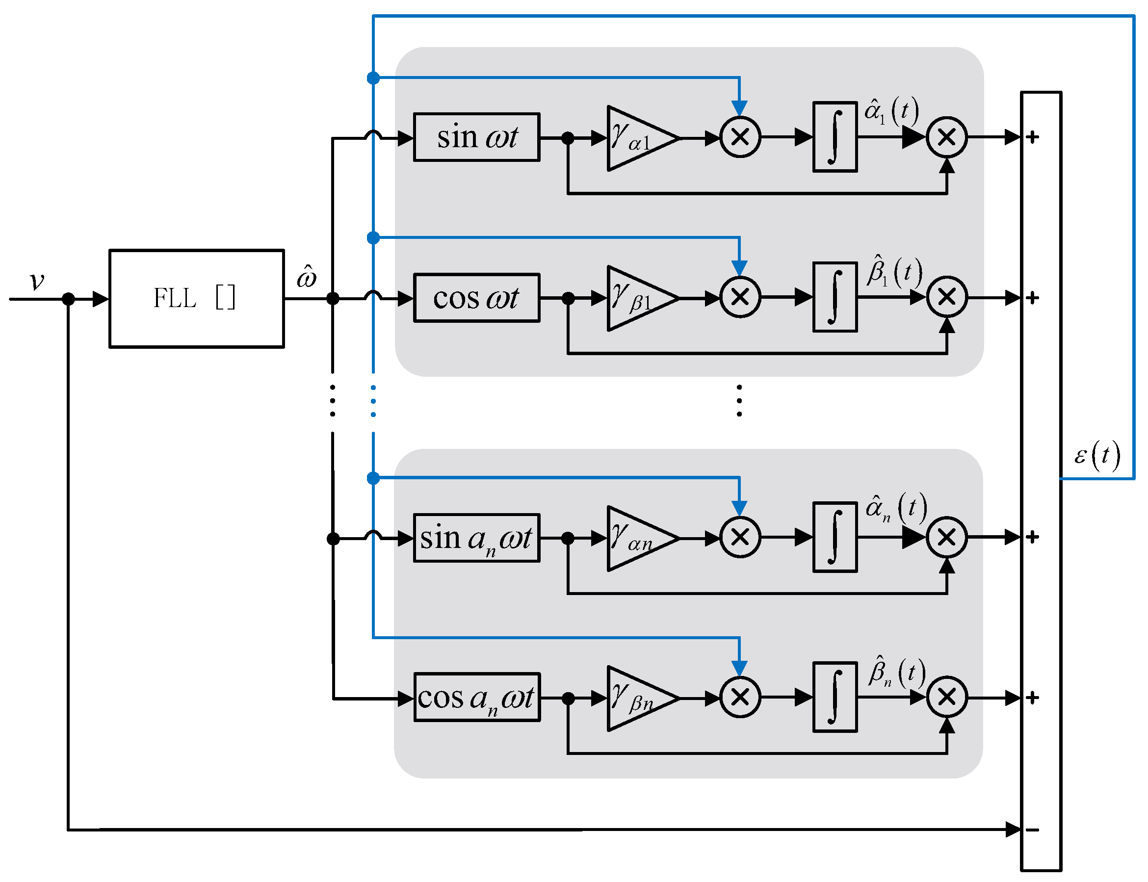
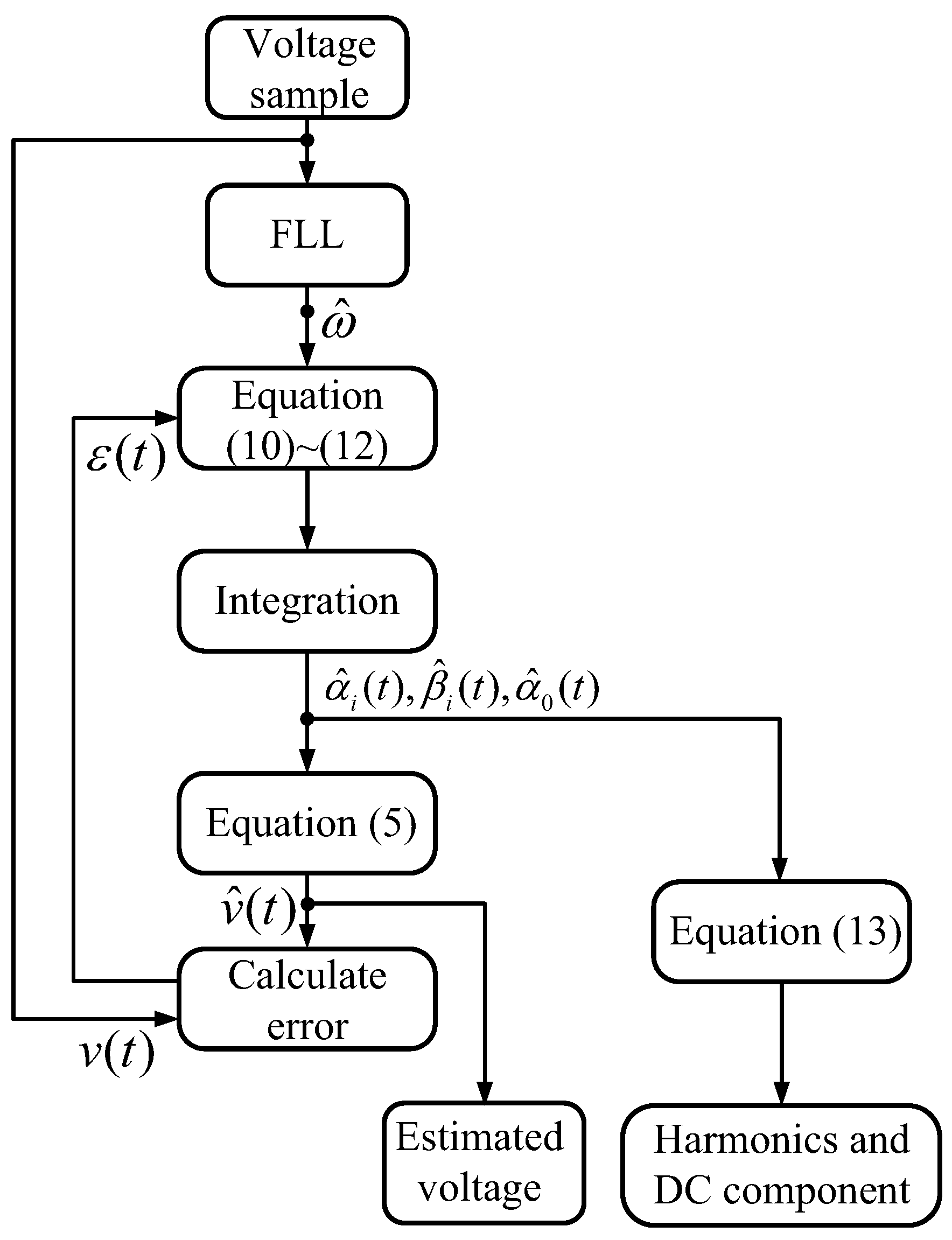
2. Voltage Parameter Detection Under Harmonically Distorted Conditions

In this section, a general scenario that contains harmonic disturbances and DC components is considered. Under these conditions, the voltage waveform deviates from its ideal sinusoidal form with half-wave symmetry. Grid voltage v with harmonics and DC components can be described as
v = i = 1 n V g i sin ( a i ω t + ϕ i ) + a 0 = V g 1 sin ( a 1 ω t + ϕ 1 ) + V g 2 sin ( a 2 ω t + ϕ 2 ) + + V g n sin ( a n ω t + ϕ n ) + a 0 = V g 1 sin ψ 1 + V g 2 sin ψ 2 + + V g n sin ψ n + a 0
where a i is a positive integer, with i > 0 and a 1 = 1 . ω is the fundamental frequency, V g n denotes the voltage amplitude of the nth-order harmonic component, and V g 1 represents the amplitude of a fundamental component. a 0 corresponds to the DC component. ϕ i represents the grid voltage phase angle, and it belongs to [0, 2 π ).
Expanding (1), we obtain
v = i = 1 n α i sin a i ω t + β i cos a i ω t + a 0 = V g 1 cos ϕ 1 sin a 1 ω t + V g 1 sin ϕ 1 cos a 1 ω t + + V g n cos ϕ n sin a n ω t + V g n sin ϕ n cos a n ω t + a 0 = α 1 sin a 1 ω t + β 1 cos a 1 ω t + + α n sin a n ω t + β n cos a n ω t + a 0
where
α i = V g i cos ϕ i , i > 0 β i = V g i sin ϕ i , i > 0
It is obvious that the grid voltage amplitude of the fundamental and harmonic component can be calculated as
V g i = α i 2 + β i 2
Thus, as long as we obtain the estimation of parameters α 1 , , α n and β 1 , , β n , the grid voltage amplitude is determined. Therefore, we present the adaptive method employed to estimate these parameters. The framework of the proposed method is illustrated in Figure 1. The grid voltage estimation described in (2) can be formulated as follows:
v ^ ( t ) = i = 1 n [ α ^ i ( t ) sin a i ω t + β ^ i ( t ) cos a i ω t ] + α ^ 0 ( t ) = α ^ 1 ( t ) sin a 1 ω t + β ^ 1 ( t ) cos a 1 ω t + + α ^ n ( t ) sin a n ω t + β ^ n ( t ) cos a n ω t + α ^ 0 ( t )
where α ^ i ( t ) is the estimation of α i . And β ^ i ( t ) is the estimation of β i , where subscript i represents 1 , , n . Accordingly, the estimation error is defined as
ε ( t ) = v ^ ( t ) v ( t ) = α ^ 1 ( t ) sin ω t + β ^ 1 ( t ) cos ω t + + α ^ n ( t ) sin a n ω t + β ^ n ( t ) cos a n ω t + α ^ 0 ( t ) v ( t )
Using (2), the estimation error results in
ε ( t ) = α ˜ 1 ( t ) sin ω t + β ˜ 1 ( t ) cos ω t + + α ˜ n ( t ) sin a n ω t + β ˜ n ( t ) cos a n ω t + α ˜ 0 ( t )
where we have
α ˜ i ( t ) = α ^ i ( t ) α i , i = 1 , , n
β ˜ i ( t ) = β ^ i ( t ) β i , i = 1 , , n
Using the adaptive algorithm [26], the adaptive estimator can be designed as
α ^ ˙ i ( t ) = γ α i ε ( t ) sin a i ω t
β ^ ˙ i ( t ) = γ β i ε ( t ) cos a i ω t
α ^ ˙ 0 ( t ) = γ 0 ε ( t )
where γ α i , γ β i , γ 0 > 0 , and they are constant parameters designed for the proposed estimator.
Therefore, based on the estimated parameters of α i and β i , the amplitude of the harmonic voltage component is calculated as
V ^ g i = α ^ i 2 + β ^ i 2
where V ^ g i is the estimation of the voltage amplitude of fundamental and harmonic component V g i . α ^ i and β ^ i represent the cosine and sine components of the grid voltage estimation V ^ g i , respectively.
The stability of the proposed estimator is analyzed by defining the following Lyapunov function:
V ( t ) = α ˜ 1 2 ( t ) 2 γ α 1 + β ˜ 1 2 ( t ) 2 γ β 1 + + α ˜ n 2 ( t ) 2 γ α n + β ˜ n 2 ( t ) 2 γ β n + α ˜ 0 2 ( t ) 2 γ 0
Subsequently, taking the derivative of (14) yields
V ˙ ( t ) = α ˜ 1 ( t ) α ˜ ˙ 1 ( t ) γ α 1 + β ˜ 1 ( t ) β ˜ ˙ 1 ( t ) γ β 1 + + α ˜ n ( t ) α ˜ ˙ n ( t ) γ α n + β ˜ n ( t ) β ˜ ˙ n ( t ) γ β n + α ˜ 0 ( t ) α ˜ ˙ 0 ( t ) γ 0
From (8) and (9),
α ˜ ˙ i ( t ) = α ^ ˙ i ( t ) = γ α i ε ( t ) sin a i ω t
β ˜ ˙ i ( t ) = β ^ ˙ i ( t ) = γ β i ε ( t ) cos a i ω t
Substituting (16) and (17) into (15) yields the following result:
V ˙ ( t ) = ε ( t ) [ α ˜ 1 ( t ) sin ω t + β ˜ 1 ( t ) cos ω t + + α ˜ n ( t ) sin ω t + β ˜ n ( t ) cos ω t + α ˜ 0 ( t ) ] = ε 2 ( t )
This concludes that
V ˙ ( t ) 0
By the Lyapunov stability theory, system (10)–(12) is globally stable. Further, in considering that sin a i ω t and cos a i ω t are persistently exciting and rich enough, through the use of the notion of the persistent excitement and the lemma in [27], the asymptotic convergent property can be proved:
lim t α ^ i ( t ) = α i
lim t β ^ i ( t ) = β i
lim t a ^ 0 = a 0
As a result, the voltage amplitude can be accurately estimated using the proposed method, achieving zero steady-state error.

3. Frequency-Locked Loop

In this section, the proposed structure is enhanced with an FLL to achieve frequency adaptability. Specifically, the grid frequency information in functions sin a i ω t and cos a i ω t can be generated by a FLL instead of using its nominal value. Therefore, the FLL proposed in [28] is chosen to provide the estimation frequency to our method. Obviously, the modified structure is robust with respect to frequency variation when compared to the structure in Section 2. This case is evaluated in the subsequent section to verify its performance.

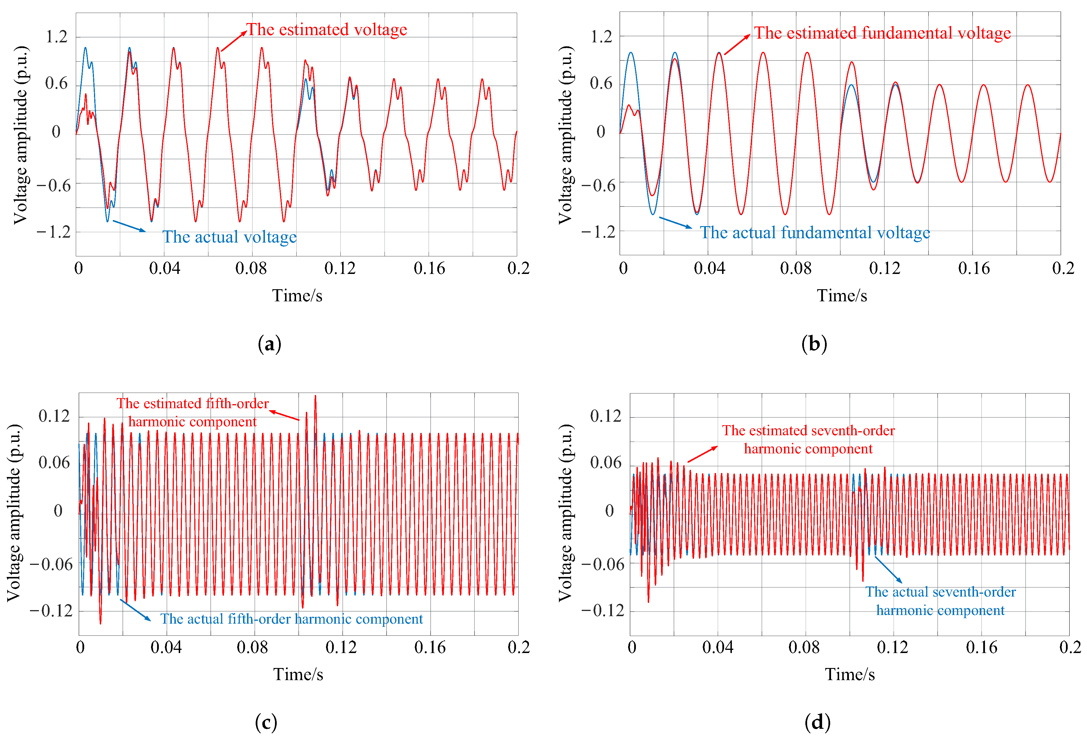
4. Simulation Results

The performance of the proposed method for detecting voltage parameters, including harmonics, is verified in this section. The simulation results based on MATLAB/SIMULINK (version: 9.12.0.2327980 (R2022a) Update 7) are provided in the following. The nominal frequency was 50 Hz, and the initial phase angle was 0. To demonstrate the effectiveness of the proposed method under voltage distortion conditions, the grid voltage contained a 0.1 p.u. fifth-order harmonic and a 0.05 p.u. seventh-order harmonic, with initial phase angles of 2 π / 3 and 4 π / 3 , respectively. Additionally, the voltage amplitude dropped from 1 p.u. to 0.6 p.u. at 0.1 s. The parameters of the proposed method were chosen as follows: γ α 1 = 200 , γ β 1 = 650 , γ α 2 = 200 , γ β 2 = 600 , γ α 3 = 200 , γ β 3 = 600 . The simulation results for detecting voltage parameters under harmonically distorted conditions are illustrated in Figure 2.
As shown in Figure 2, after a short dynamic response, the grid voltage can be accurately estimated without steady-state error, and its fifth and seventh harmonics can also be accurately extracted. When the voltage amplitude drops by 0.4 p.u. at 0.1 s, the proposed method exhibits a fast dynamic response and converges to actual values without steady-state error. Since the simulation model was built under ideal conditions, it is insufficient to fully demonstrate the reliability and performance of the proposed method in practical scenarios. Therefore, the simulation results serve only for model validation. The next section presents experimental results to validate the method’s performance under practical conditions.

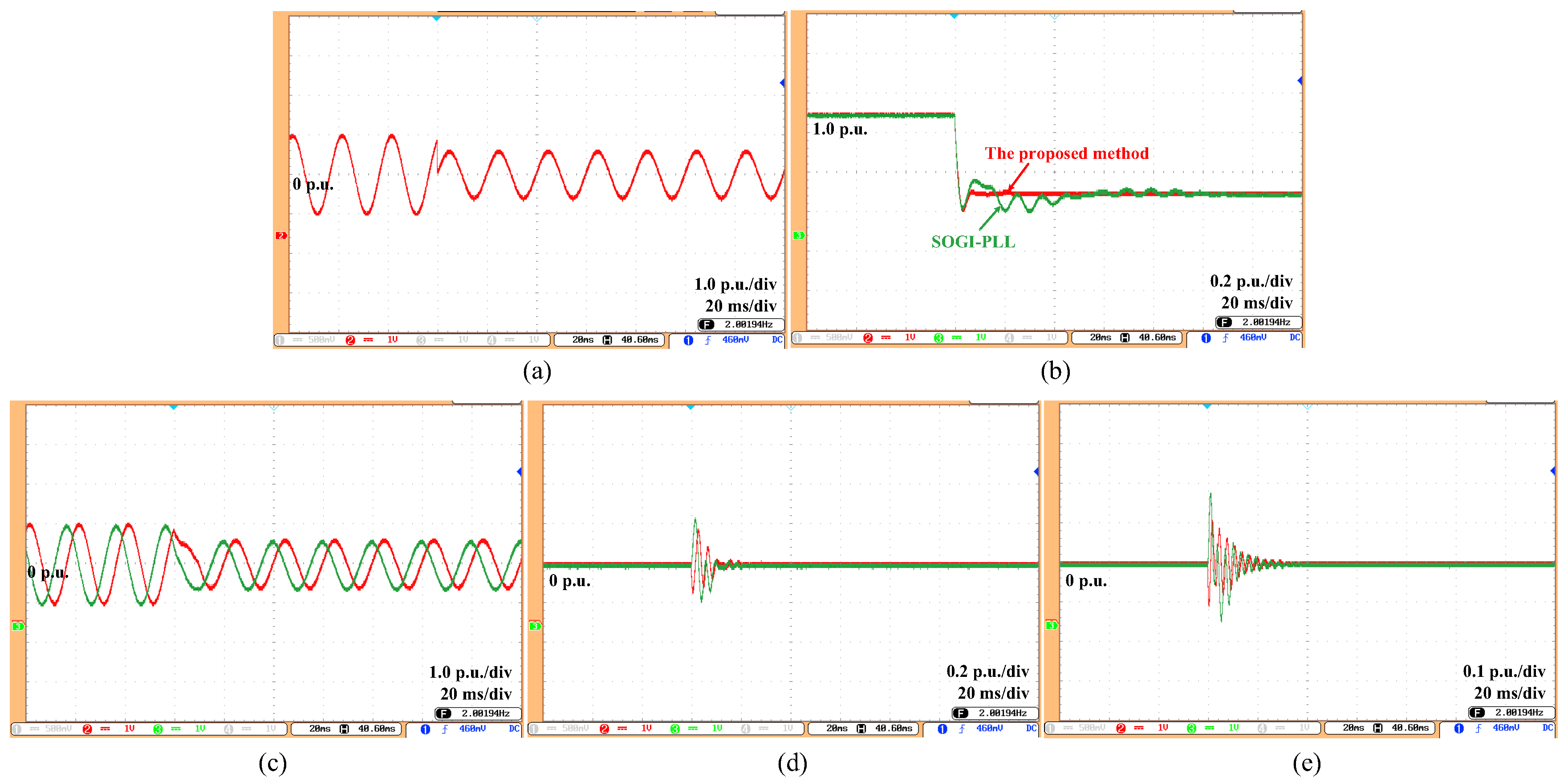
5. Experimental Results

In this section, the performance of the proposed method is evaluated using several experimental results, obtained from the method’s implementation in a digital signal processor (DSP) TMS320F28335 platform (Texas Instruments Inc., Dallas, TX, USA). The sampling frequency was 10 kHz. The general structure of the experimental model is illustrated in Figure 3. To clarify how the mathematical model is transposed into the programmed system, a workflow diagram is provided, as shown in Figure 4. For performance validation, the SOGI-PLL method was employed as a reference to compare with the newly developed technique. It is worth noting that the proposed structure we established here contains fifth- and seventh-order harmonic elimination blocks since these harmonics are dominant low-order harmonics in grid voltage. The initial parameters of the proposed method were chosen as follows: γ α 1 = 200, γ β 1 = 650, γ α 2 = 200, γ β 2 = 600, γ α 3 = 200, γ β 3 = 600.

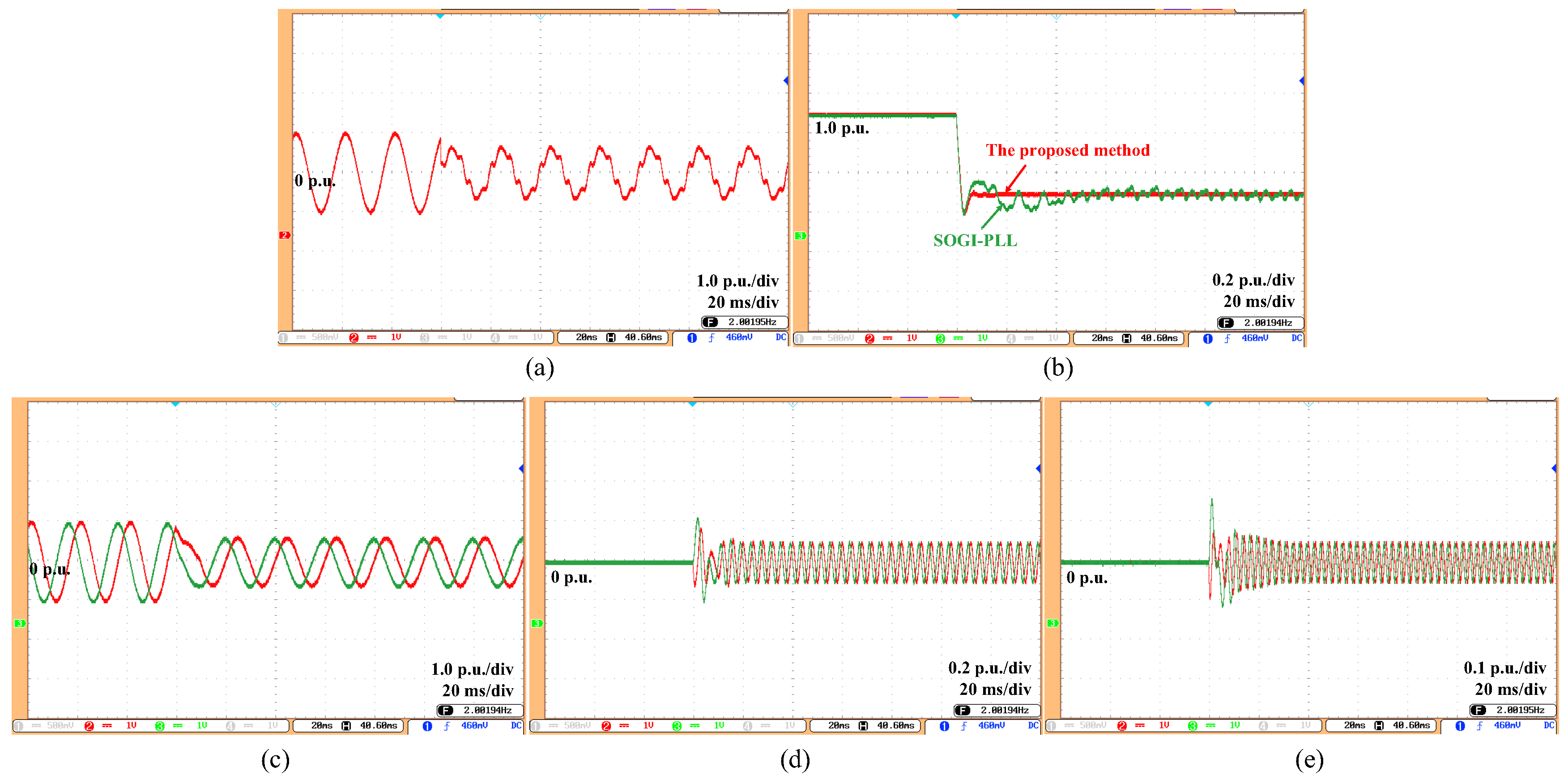
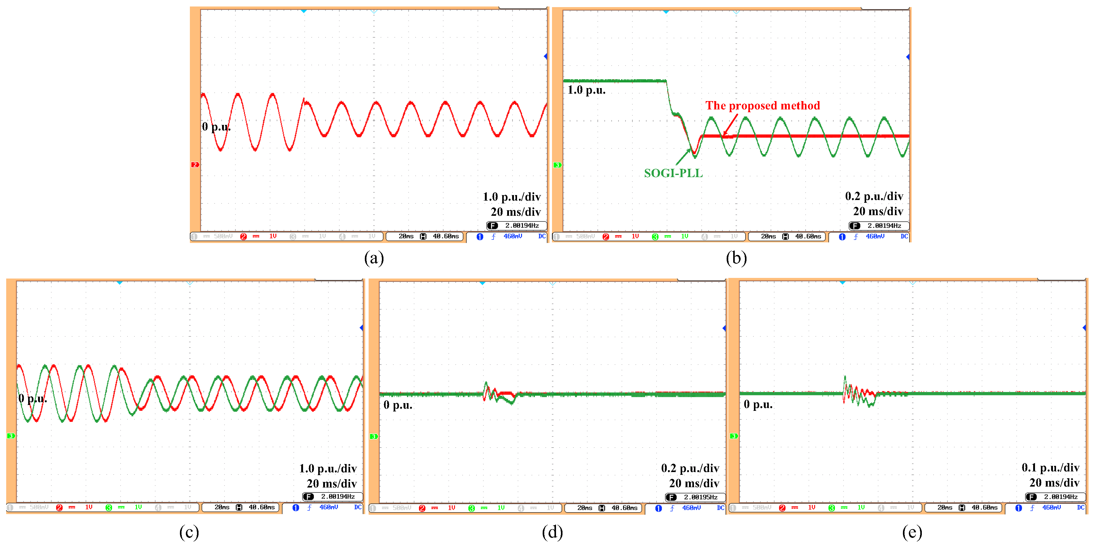
5.1. Case Without FLL
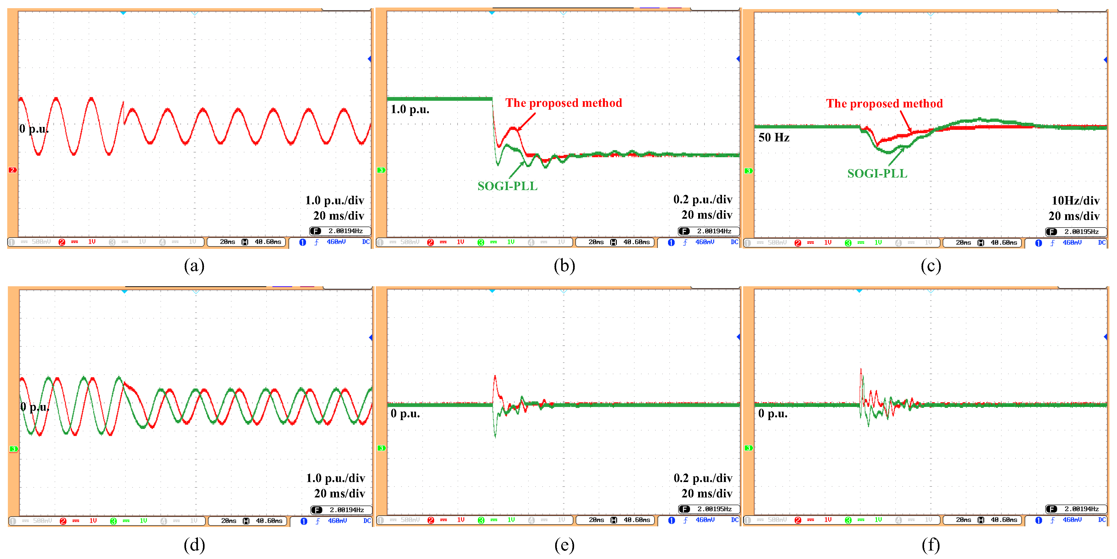
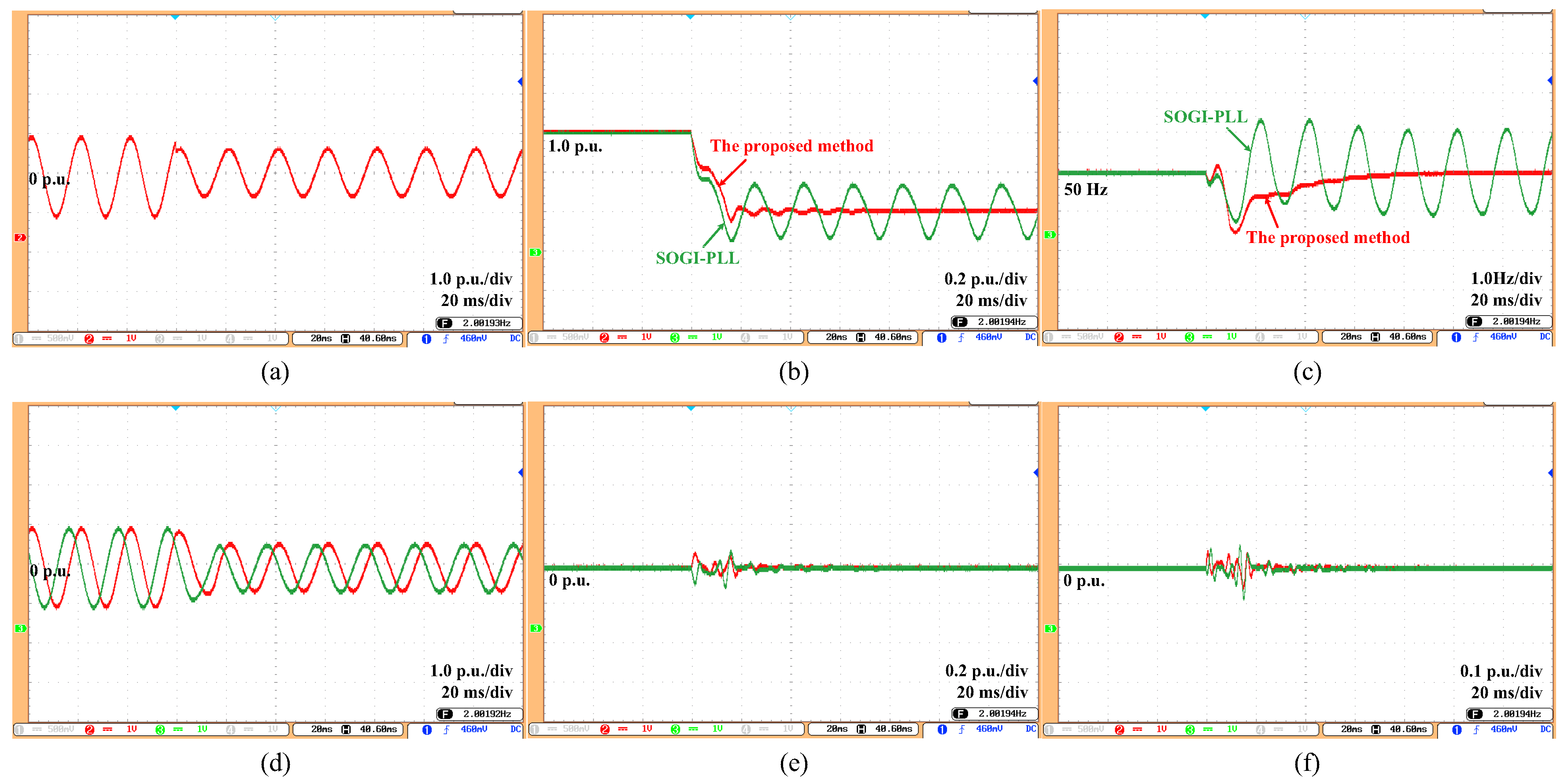
In this case, the structure without an FLL was implemented in four tests: (1) phase angle shift with amplitude drop, (2) frequency variation with amplitude drop, (3) harmonics with amplitude drop, (4) DC offset with amplitude drop. The fundamental frequency was 50 Hz, and the initial phase angle was π / 3 .
Test (1): During normal operation, the voltage is suddenly subjected to a 0.4 p.u. voltage drop and π / 3 phase jump. As illustrated in Figure 5, the experimental results under this conditions indicate that the proposed method achieves accurate tracking of the voltage amplitude with no steady-state error. Compared to the SOGI-PLL method with a settle time of 80 ms, the proposed method only takes 5.3 ms to settle. Hence, the proposed method exhibits quicker dynamic performance.
Test (2): The voltage frequency changes from 50 Hz to 51 Hz, and its amplitude decreases by 0.4 p.u. The experimental results under this condition are shown in Figure 6. As shown, the proposed method yields amplitude estimation results that exhibit significant fluctuation, primarily due to the assumption of constant frequency in this case. To address this issue, the model that contains an FLL will be tested in the next subsection.
Test (3): The grid voltage is subjected to a 0.1 p.u. fifth-order harmonic and a 0.05 p.u. seventh-order harmonic, while its amplitude decreases from 1.0 p.u. to 0.6 p.u. The corresponding experimental results are depicted in Figure 7. Clearly, the proposed method effectively removes the harmonics and accurately estimates the voltage amplitude. Notably, it also precisely extracts the fifth-order and seventh-order harmonic components from the voltage. Moreover, the proposed method has a dynamic response time of just 5.3 ms. In contrast, the SOGI-PLL exhibits a 3.2% steady-state error and a relatively slow dynamic response. More importantly, the SOGI-PLL is incapable of extracting harmonic components.
Test (4): A DC component of 0.1 p.u. is superimposed on the grid voltage, accompanied by a voltage amplitude drop of 0.4 p.u. As depicted in Figure 8, the experimental results under this condition are presented. Owing to the impact of DC bias, the SOGI-PLL has a 25% steady-state error. In contrast, the proposed method completely eliminates the impact of the DC component, demonstrating better robustness against DC bias. The experimental results in Section 5.1 are summarized in Table 2 for better clarity and comparison.

5.2. Case with FFL

In this study, the experiments of the proposed structure with an FFL were carried out. The tests were designed as follows: (1) phase angle shift with amplitude drop, (2) frequency variation of 1 Hz, (3) harmonics with amplitude drop, (4) DC offset with amplitude drop.
Test (1): The grid voltage undergoes a π / 3 phase jump and a 0.4 p.u. voltage drop. The corresponding experimental results are depicted in Figure 9. It is evident that the proposed method accurately tracks the voltage amplitude with zero steady-state error. Furthermore, due to the integration of the FLL, the proposed method is capable of estimating the voltage frequency. In terms of both voltage amplitude and frequency estimation, the dynamic response of the proposed method outperforms that of the SOGI-PLL.
Test (2): The grid voltage in this case is first at its nominal value and then undergoes a 1 Hz step change at t = 1 s. Figure 10 shows the obtained results in response to this case. The proposed method achieves zero steady-state error in estimating voltage amplitude and also accurately estimates voltage frequency, which is attributed to the integration of the FLL. Additionally, the proposed method exhibits a superior dynamic response, with a settling time of around 25 ms, compared to the SOGI-PLL’s settling time of approximately 56 ms.
Test (3): The grid voltage is affected by 0.1 p.u. fifth-order harmonics and 0.05 p.u. seventh-order harmonics. Meanwhile, the amplitude drops from 1.0 p.u. to 0.6 p.u. Figure 11 shows the experimental results of voltage amplitude and frequency under voltage distortion conditions. The proposed method achieves precise and steady-state error-free estimation of voltage amplitude under harmonic interference. In addition, the dynamic response is faster than that of the SOGI-PLL.
Test (4): A DC component of 0.1 p.u. is superimposed on the grid voltage, accompanied by a voltage amplitude drop of 0.4 p.u. In Figure 12, it is shown that due to the influence of the DC bias, the voltage amplitude estimation of SOGI-PLL has a 25% steady-state error and the estimated result oscillates. In contrast, the proposed method completely eliminates the impact of the dc component, achieving accurate voltage amplitude and frequency estimation. To clearly present the performance of the proposed method, the experimental results in Section 5.2 are organized and illustrated in Table 3.

5.3. Comparison with Traditional Methods

In order to demonstrate superior efficiency, we list the detection time of the proposed method and several traditional methods in Table 4, including MAF-PLL [29], VSRF-PLL [30], DDSRF-PLL [31], LSRF-PLL, DSOGI-PLL [32], and MRF-PLL [33]. Obviously, in comparison with these traditional methods, the proposed method has great advantages in detection speed.

6. Conclusions

In this paper, we proposed a voltage parameters adaptive detection method for the performance evaluation or low-voltage ride through (LVRT) operation of grid-tied new energy generation systems in the presence of harmonics and asymmetry in the grid voltage. Moreover, compared with traditional methods, the proposed method has the following advantages:
  • The novel method has great advantages in detection speed;
  • The novel method achieves accurate tracking of the voltage parameters with zero steady-state error under voltage distortion conditions;
  • The novel method is able to extract the harmonics and the DC component without steady-state error.
However, when frequency varies, the proposed method exhibits slight fluctuations and poor dynamic performance, as it assumes that the frequency remains constant. To address this, an FFL is incorporated into the method to estimate frequency, but this increases the algorithm’s computational complexity. Future work will focus on developing a voltage frequency adaptive estimation method to ensure great performance and low computational burden under frequency variation conditions.

Author Contributions

Conceptualization, W.H., Z.D., and G.L.; methodology, W.H. and Z.D.; writing—original draft preparation, W.H., Z.D., and S.L.; writing—review and editing, G.L., S.L., and Q.S.; software, N.L. and J.M.; supervision, Z.D. and Q.S.; project administration, Z.D. and Q.S.; funding acquisition, Z.D. and Q.S. All authors have read and agreed to the published version of the manuscript.

Funding

This work was supported by the National Key Research and Development Program of China under Grant 2023YFB4203200.

Data Availability Statement

All data underlying the conclusions of this study are fully provided in the manuscript. Further access may be obtained from the corresponding author.

Conflicts of Interest

Authors Qitao Sun, Nana Lu and Jinke Ma were employed by the Ming Yang Smart Energy Group Limited. The remaining authors declare that the research was conducted in the absence of any commercial or financial relationships that could be construed as a potential conflict of interest.

Abbreviations

The following abbreviations are used in this manuscript:
FLLfrequency-locked loop;
PLLphase-locked loop;
pPLLspower-based PLLs;
LPF-PLLlow-pass filter-based pPLL;
DFAC-pPLLdouble-frequency and amplitude compensation-based pPLL;
QSG-PLLsquadrature signal generation-based PLLs;
SOGI-PLLsecond-order generalized integrator-based phase-locked loop;
MAF-PLLsmoving average filter-based pPLLs;
TD-PLLtransfer delay-PLL;
VTD-PLLvariable-length delay-PLL;
ATD-PLLadaptive transfer delay-PLL;
NTD-PLLnon-frequency-dependent TD-PLL;
QSG-FLLsquadrature signal generation-based FLLs;
SOGI-FLLsecond-order generalized integrator-based FLL;
TD-AFLLtransfer delay-based adaptive frequency locked loop;
DDSRF-PLLDecoupled double synchronous reference frame PLL;
LSRF-PLLlow-pass filter-based synchronous reference frame PLL;
VSPF-PLLvariable sampling period filter phase-locked loop
DSOGI-PLLdual second-order generalized integrator-based phase-locked loop;
MRF-PLLmultiple-reference-frame phase-locked loop;
LVRTlow-voltage ride through.

References

  1. Khan, I.; Doolla, S. Improved fault ride-through response of grid forming inverters under symmetrical and asymmetrical faults. IEEE Trans. Energy Convers. 2025, 40, 394–408. [Google Scholar] [CrossRef]
  2. Feng, Y.; Huang, W.; Jin, Z.; Li, Y.; Shen, Z.J.; Shuai, Z. Voltage Support Strategy for Improving Power Transfer Capability of Grid-Connected Converter Under Unbalanced Conditions. IEEE Trans. Power Electron. 2024, 39, 7863–7875. [Google Scholar] [CrossRef]
  3. Xiao, F.; Dong, L.; Li, L.; Liao, X. Fast voltage detection method for grid-tied renewable energy generation systems under distorted grid voltage conditions. IET Power Electron. 2017, 10, 1487–1493. [Google Scholar] [CrossRef]
  4. Ma, C.; Gao, F.; He, G.; Li, G. Fast voltage detection method for the voltage ride through operation of grid-tied renewable energy generation systems. In Proceedings of the 2014 IEEE Applied Power Electronics Conference and Exposition—APEC 2014, Fort Worth, TX, USA, 16–20 March 2014; pp. 386–391. [Google Scholar]
  5. Ismail, F.; Jamaludin, J.; Abd Rahim, N. Enhanced Energy Delivery for Solar PV Distributed Generators at Voltage Sags. IEEE Access 2023, 11, 139688–139705. [Google Scholar] [CrossRef]
  6. Styvaktakis, E.; Bollen, M.H.; Gu, I.Y. Automatic classification of power system events using RMS voltage measurements. In Proceedings of the IEEE Power Engineering Society Summer Meeting, Chicago, IL, USA, 21–25 July 2002; Volume 2, pp. 824–829. [Google Scholar]
  7. Naidoo, R.; Pillay, P. A new method of voltage sag and swell detection. IEEE Trans. Power Deliv. 2007, 22, 1056–1063. [Google Scholar] [CrossRef]
  8. Zou, W.; Su, S. Voltage flicker detection based on wavelet fourier transform. In Proceedings of the 2011 International Conference on Electrical and Control Engineering, Yichang, China, 16–18 September 2011; pp. 4218–4220. [Google Scholar]
  9. Golestan, S.; Ramezani, M.; Guerrero, J.M.; Freijedo, F.D.; Monfared, M. Moving average filter based phase-locked loops: Performance analysis and design guidelines. IEEE Trans. Power Electron. 2014, 29, 2750–2763. [Google Scholar] [CrossRef]
  10. Golestan, S.; Monfared, M.; Freijedo, F.D.; Guerrero, J.M. Design and tuning of a modified power-based PLL for single-phase grid-connected power conditioning systems. IEEE Trans. Power Electron. 2012, 27, 3639–3650. [Google Scholar] [CrossRef]
  11. Avudaiappan, S.K.; Joshi, S.T.; Ganesan, S.I.; Chilakapati, N. A high-speed frequency adaptive grid synchronization technique for single-phase inverter under distorted grid conditions. Sādhanā 2022, 47, 69. [Google Scholar] [CrossRef]
  12. Ciobotaru, M.; Teodorescu, R.; Blaabjerg, F. A new single-phase PLL structure based on second order generalized integrator. In Proceedings of the 2006 37th IEEE Power Electronics Specialists Conference, Jeju, Republic of Korea, 18–22 June 2006; pp. 1–6. [Google Scholar]
  13. Lubura, S.; Šoja, M.; Lale, S.; Ikić, M. Single-phase phase locked loop with DC offset and noise rejection for photovoltaic inverters. IET Power Electron. 2014, 7, 2288–2299. [Google Scholar] [CrossRef]
  14. Karimi-Ghartemani, M.; Khajehoddin, S.A.; Jain, P.K.; Bakhshai, A.; Mojiri, M. Addressing DC component in PLL and notch filter algorithms. IEEE Trans. Power Electron. 2011, 27, 78–86. [Google Scholar] [CrossRef]
  15. Akhtar, M.A.; Choudhury, S.; Saha, S. LQR based PI controller tuning for transport delay-phase locked loop (TD-PLL). In Proceedings of the 2018 3rd International Innovative Applications of Computational Intelligence on Power, Energy and Controls with their Impact on Humanity (CIPECH), Ghaziabad, India, 1–2 November 2018; pp. 34–38. [Google Scholar]
  16. Akhtar, M.A.; Saha, S. A Systematic Approach of Loop Filter Tuning of TD-Based PLLs Using LQR-Based Approach Considering Time Delay. IEEE J. Emerg. Sel. Top. Power Electron. 2022, 10, 2424–2434. [Google Scholar] [CrossRef]
  17. Akhtar, M.A.; Saha, S.; Pal, D.; Verma, A.K.; Tir, Z. A Systematic Approach to Design Amplitude Estimators for NTD-PLL: Performance Improvement Under Abnormal Grid Disturbances. IEEE Trans. Power Electron. 2023, 38, 5456–5468. [Google Scholar] [CrossRef]
  18. Pompodakis, E.E.; Boubaris, A.; Voglitsis, D.; Papanikolaou, N.; Yiannis, K.; Karapidakis, E.S. Variable-Length Transfer Delay-Based Synchronization Approach for Improved Dynamic Performance in Single-Phase Inverters. IEEE Access 2024, 12, 151331–151347. [Google Scholar] [CrossRef]
  19. Golestan, S.; Guerrero, J.M.; Abusorrah, A.; Al-Hindawi, M.M.; Al-Turki, Y. An adaptive quadrature signal generation-based single-phase phase-locked loop for grid-connected applications. IEEE Trans. Ind. Electron. 2016, 64, 2848–2854. [Google Scholar] [CrossRef]
  20. Pin, G.; Chen, B.; Fedele, G.; Parisini, T. Robust Frequency-Adaptive PLL with Lyapunov Stability Guarantees. In Proceedings of the 2020 IEEE Conference on Control Technology and Applications (CCTA), Montreal, QC, Canada, 24–26 August 2020; pp. 498–503. [Google Scholar]
  21. Pin, G.; Chen, B.; Fedele, G.; Parisini, T. Robust Frequency-Adaptive Quadrature Phase-Locked-Loops with Lyapunov-Certified Global Stability. IEEE Trans. Control Syst. Technol. 2023, 31, 467–474. [Google Scholar] [CrossRef]
  22. Prakash, S.V.; Behera, S.; N, V.R.N.; Karthik, M. SOGI-PLL Based Control Technique for the Single-Phase Single-Stage Grid Connected PV System. In Proceedings of the 2023 First International Conference on Cyber Physical Systems, Power Electronics and Electric Vehicles (ICPEEV), Hyderabad, India, 28–30 September 2023; pp. 1–5. [Google Scholar]
  23. Dai, Z.; Zhang, Z.; Yang, Y.; Blaabjerg, F.; Huangfu, Y.; Zhang, J. A fixed-length transfer delay based adaptive frequency-locked loop for single-phase systems. IEEE Trans. Power Electron. 2018, 34, 4000–4004. [Google Scholar] [CrossRef]
  24. Dai, Z.; Lin, W. Adaptive estimation of three-phase grid voltage parameters under unbalanced faults and harmonic disturbances. IEEE Trans. Power Electron. 2016, 32, 5613–5627. [Google Scholar] [CrossRef]
  25. Surbhi; Teja, A.V.R.; J, K. A Novel Variable Time Delay FLL Based Estimation of Positive and Negative Sequence Components of Grid. In Proceedings of the IECON 2023—49th Annual Conference of the IEEE Industrial Electronics Society, Singapore, 16–19 October 2023; pp. 1–6. [Google Scholar]
  26. Tao, G. Adaptive Control Design and Analysis; John Wiley & Sons: Hoboken, NJ, USA, 2003; pp. 99–111. [Google Scholar]
  27. Goodwin, G.C.; Welsh, J.S. Self excited closed loop parametric estimation in the presence of noise undermodelling. In Proceedings of the 2002 American Control Conference (IEEE Cat. No. CH37301), Anchorage, AK, USA, 8–10 May 2002; Volume 4, pp. 3331–3336. [Google Scholar]
  28. Rodríguez, P.; Luna, A.; Candela, I.; Mujal, R.; Teodorescu, R.; Blaabjerg, F. Multiresonant frequency-locked loop for grid synchronization of power converters under distorted grid conditions. IEEE Trans. Ind. Electron. 2010, 58, 127–138. [Google Scholar] [CrossRef]
  29. Wang, L.; Jiang, Q.; Hong, L.; Zhang, C.; Wei, Y. A novel phase-locked loop based on frequency detector and initial phase angle detector. IEEE Trans. Power Electron. 2012, 28, 4538–4549. [Google Scholar] [CrossRef]
  30. Carugati, I.; Maestri, S.; Donato, P.G.; Carrica, D.; Benedetti, M. Variable sampling period filter PLL for distorted three-phase systems. IEEE Trans. Power Electron. 2011, 27, 321–330. [Google Scholar] [CrossRef]
  31. Rodríguez, P.; Pou, J.; Bergas, J.; Candela, J.I.; Burgos, R.P.; Boroyevich, D. Decoupled double synchronous reference frame PLL for power converters control. IEEE Trans. Power Electron. 2007, 22, 584–592. [Google Scholar] [CrossRef]
  32. Pinto, J.; Carvalho, A.; Rocha, A.; Araújo, A. Comparison of DSOGI-based PLL for phase estimation in three-phase weak grids. Electricity 2021, 2, 244–270. [Google Scholar] [CrossRef]
  33. Golestan, S.; Monfared, M.; Freijedo, F.D. Design-oriented study of advanced synchronous reference frame phase-locked loops. IEEE Trans. Power Electron. 2012, 28, 765–778. [Google Scholar] [CrossRef]
Figure 1. Structure of the proposed method.
Symmetry 17 00975 g001
Figure 2. Simulation results under harmonic distortion with amplitude drop (without FLL): (a) estimated and actual grid voltage, (b) estimated and actual fundamental voltage, (c) estimated and actual fifth-order harmonic component, (d) estimated and actual seventh-order harmonic component.
Symmetry 17 00975 g002
Figure 3. General structure of the experimental model.
Symmetry 17 00975 g003
Figure 4. Programming workflow of the proposed method.
Symmetry 17 00975 g004
Figure 5. Estimation results under phase angle jump with amplitude drop (without FLL). (a) Grid voltage, (b) grid amplitude (estimated), (c) fundamental voltage and its orthogonal component (estimated), (d) estimated 5th-order harmonic component, (e) estimated 7th-order harmonic component.
Symmetry 17 00975 g005
Figure 6. Estimation results under frequency variation with amplitude drop (without FLL). (a) Grid voltage, (b) grid amplitude (estimated), (c) fundamental voltage and its orthogonal component (estimated), (d) 5th-order harmonic component (estimated), (e) 7th-order harmonic component (estimated).
Symmetry 17 00975 g006
Figure 7. Estimation results under harmonic distortion with amplitude drop (without FLL). (a) Grid voltage, (b) grid amplitude (estimated), (c) fundamental voltage and its orthogonal component (estimated), (d) 5th-order harmonic component (estimated), (e) 7th-order harmonic component (estimated).
Symmetry 17 00975 g007
Figure 8. Estimation results under dc offset with amplitude drop (without FLL). (a) Grid voltage, (b) grid amplitude (estimated), (c) fundamental voltage and its orthogonal component (estimated), (d) 5th-order harmonic component (estimated), (e) 7th-order harmonic component (estimated).
Symmetry 17 00975 g008
Figure 9. Estimation results under phase angle jump with amplitude drop (with FLL). (a) Grid voltage, (b) grid amplitude (estimated), (c) grid frequency (estimated), (d) fundamental voltage and its orthogonal component (estimated), (e) 5th-order harmonic component (estimated), (f) 7th-order harmonic component (estimated).
Symmetry 17 00975 g009
Figure 10. Estimation results under frequency variation (with FLL). (a) Grid voltage, (b) grid amplitude (estimated), (c) grid frequency (estimated) (d) fundamental voltage and its orthogonal component (estimated), (e) 5th-order harmonic component (estimated), (f) 7th-order harmonic component (estimated).
Symmetry 17 00975 g010
Figure 11. Estimation results under harmonic distortion with amplitude drop (with FLL). (a) Grid voltage, (b) grid amplitude (estimated), (c) grid frequency (estimated) (d) fundamental voltage and its orthogonal component (estimated), (e) 5th-order harmonic component (estimated), (f) 7th-order harmonic component (estimated).
Symmetry 17 00975 g011
Figure 12. Estimation results under dc offset with amplitude drop (with FLL). (a) Grid voltage, (b) grid amplitude (estimated), (c) grid frequency (estimated), (d) fundamental voltage and its orthogonal component (estimated), (e) 5th-order harmonic component (estimated), (f) 7th-order harmonic component (estimated).
Symmetry 17 00975 g012
Table 1. Summary of aforementioned methods and their characteristics.
MethodCharacteristicMethodCharacteristic
RMS-based methodA minimum delay of one cyclePeak Voltage Detection MethodA minimum delay of a half-cycle
DFT-based methodA minimum delay of one cycleLPF-PLLSlow dynamic response
MAF-PLLSlow dynamic responseDFAC-pPLLA satisfactory dynamic response
TOGI-PLLDC offset rejection capabilityMSOGI-PLLBetter harmonic immunity
TD-PLLAffected by frequency deviationsNTD-PLLSteady-state error exists
VTD-PLLComplex stability analysisATD-PLLGood steady-state performance
GQPLLFrequency adaptationTD-AFLLObvious steady-state error under harmonic disturbances
Proposed methodWithout steady-state error under voltage distortion conditions
Table 2. Summary of experiment results in Section 5.1.
Experiment ConditionsSOGI-PLLProposed Method (No FLL)
test (1)settle time: last for 80 mssettle time: 5.3 ms
test (2)minor fluctuationlarge fluctuation
test (3)3.2% steady-state errorzero steady-state error
test (4)25% steady-state errorzero steady-state error
Table 3. Summary of experiment results in Section 5.2.
Experiment ConditionsSOGI-PLLProposed Method (with FLL)
test (1)settle time: last for 80 mssettle time: about 40 ms
test (2)settle time: about 56 mssettle time: about 25 ms
test (3)3.2% steady-state errorzero steady-state error
test (4)25% steady-state errorzero steady-state error
Table 4. Detection time comparison of different methods.
Detection MethodMaximum Detection Time Without Grid Voltage Distortion (ms)Detection Time with Low-Order Harmonic Distortion (ms)
DDSRF-PLL25longer than 25
VSPF-PLL2525
MAF-PLL20longer than 20
LSRF-PLL60longer than 60
MRF-PLL40longer than 40
DSOGI-PLL30longer than 30
Proposed method4.1610.7
Disclaimer/Publisher’s Note: The statements, opinions and data contained in all publications are solely those of the individual author(s) and contributor(s) and not of MDPI and/or the editor(s). MDPI and/or the editor(s) disclaim responsibility for any injury to people or property resulting from any ideas, methods, instructions or products referred to in the content.

