Article

Power Oscillation Emergency Support Strategy for Wind Power Clusters Based on Doubly Fed Variable-Speed Pumped Storage Power Support

School of Electrical Engineering, Shenyang University of Technology, Shenyang 110870, China
*
Author to whom correspondence should be addressed.
Symmetry 2025, 17(6), 964; https://doi.org/10.3390/sym17060964
Submission received: 17 May 2025 / Revised: 11 June 2025 / Accepted: 15 June 2025 / Published: 17 June 2025
(This article belongs to the Special Issue Advances in Intelligent Power Electronics with Symmetry/Asymmetry)

Abstract

Single-phase short-circuit faults are severe asymmetrical fault modes in high renewable energy power systems. They can easily cause large-scale renewable energy to enter the low-voltage ride-through (LVRT) state. When such symmetrical or asymmetrical faults occur in the transmission channels of high-proportion wind power clusters, they may trigger the tripping of thermal power units and a transient voltage drop in most wind turbines in the high-proportion wind power area. This causes an instantaneous active power deficiency and poses a low-frequency oscillation risk. To address the deficiencies of wind turbine units in fault ride-through (FRT) and active frequency regulation capabilities, a power emergency support scheme for wind power clusters based on doubly fed variable-speed pumped storage dynamic excitation is proposed. A dual-channel energy control model for variable-speed pumped storage units is established via AC excitation control. This model provides inertia support and FRT energy simultaneously through AC excitation control of variable-speed pumped storage units. Considering the transient stability of the power network in the wind power cluster transmission system, this scheme prioritizes offering dynamic reactive power to support voltage recovery and suppresses power oscillations caused by power deficiency during LVRT. The electromagnetic torque completed the power regulation within 0.4 s. Finally, the effectiveness of the proposed strategy is verified through modeling and analysis based on the actual power network of a certain region in Northeast China.

1. Introduction

In the power system, with the continuous integration of high-proportion new energy units [1,2,3], the overall rotational inertia of the grid shows a downward trend [4,5,6], and transient frequency security has become a key challenge restricting the development of the new power network. The factors causing low-frequency oscillation are rather complex. They not only include permanent power disturbances caused by faults such as the disconnection of new energy units, but also short-term power surges brought about by large-scale low-voltage ride-through of new energy units due to short-circuit faults, which can also lead to rapid changes in system frequency. Moreover, if faults occur in the 500-kilovolt transmission channels between regional grids, they may also cause low-frequency oscillation problems throughout the entire network. Fault ride-through refers to the situation where, in the event of a fault in the power system, the wind turbine can remain connected to the grid without being disconnected, and can quickly return to its normal operating state after the fault is cleared. Low-voltage ride-through is a special case of fault ride-through in power systems, which can maintain grid-connected operation without disconnection within a certain period of time and a certain degree of low-voltage range.
Nowadays, regional grids are closely connected. Multiple wind turbine units form a wind power cluster and transmit electricity outward through high-voltage interconnection lines. After a short-circuit grounding fault occurs in a 500-kilovolt power channel, if the number of wind turbines entering the low-voltage ride-through state increases under fault conditions, the transient voltage drop of most wind turbines in large-scale new energy bases may trigger low-voltage ride-through protection, instantly generating a significant active power deficiency. According to China’s power grid connection rules, the active power recovery rate of wind turbines after fault clearance should not be lower than 0.1 p.u./s. Before the wind turbine output recovers, regional grids with a high proportion of new energy are at risk of low-frequency oscillation. With the continuous large-scale integration of new energy [7,8,9,10], when the number of wind turbines entering the low-voltage ride-through state increases under fault conditions, the system frequency will further decrease, posing a risk of triggering low-frequency load shedding. Low-frequency oscillation can lead to the collapse of the power grid, cause tripping of connecting lines, and increase the risk of system power outages. Traditional methods generally involve strengthening the construction of backup channels between regional grids or enhancing the identification and verification of the low-voltage ride-through characteristics of wind power, and taking measures to limit the output of wind power clusters.
Pumped storage power stations have multiple functions such as peak shaving and valley filling, frequency and phase regulation, and emergency backup [11,12,13,14], and are currently the most mature and economically optimal large-scale energy storage methods. They play a significant role in the power system, effectively solving the peak shaving problem of the grid and ensuring its safe, stable, and economic operation. The fast response speed and bidirectional power adjustment capabilities of pumped storage power stations [15,16,17,18] make them irreplaceable in assisting the integration of centralized/distributed new energy and grid operation. Compared with traditional discrete and unidirectional control resources such as generator tripping and load shedding, they are very suitable for emergency control after short-term power disturbances [19,20]. The issue of power system frequency regulation has received extensive attention, and many studies have focused on the key role of energy storage systems in this regard. Some scholars have proposed an integrated strategy aimed at stabilizing the grid frequency through primary frequency regulation using hybrid energy storage systems, providing a new approach to addressing frequency fluctuations [21]. Some research has explored the coordinated control of traditional units, wind energy, and battery energy storage systems to enhance the effective support for frequency regulation services, and evaluated the effectiveness of energy storage resources in frequency regulation in single-area power systems. Their studies provide a reference for measuring the actual contribution of energy storage systems in frequency regulation and offer important theoretical and technical support for addressing the challenges of power system frequency fluctuations and ensuring grid stability [22,23,24,25].
In recent years, variable-speed pumped storage units have received extensive attention due to their significant role in power system frequency regulation and stable power supply. Many studies have focused on optimizing the control strategies and performance evaluation of variable-speed pumped storage units to enhance their effectiveness in suppressing power oscillations in regional power systems.
Regarding the control strategies of variable-speed pumped storage units, Reference [26] proposed a speed pullback control and adaptive strategy to optimize the operational performance of variable-speed pumped storage units. Reference [27] studied the power regulation characteristics of variable-speed pumped storage units in pumping mode, providing a theoretical basis for improving their regulation capabilities through quantitative analysis. Reference [28] conducted stability analysis and singular perturbation model reduction for variable-speed pumped storage units (VSPS) adopting rapid speed control strategies, providing a new approach for the small-signal oscillation stability analysis of the system. Additionally, some studies have focused on the performance of VSPS under different operating modes. Reference [29] proposed an improved start-up strategy for large-rated VSPS operating in pumping mode. Reference [30] analyzed the hydraulic disturbance characteristics and power control of fixed-speed and variable-speed pumped storage units in generating mode, offering new ideas for optimizing their operational performance. Reference [31] proposed a multi-time-scale model reduction strategy, providing an effective means for the oscillation stability analysis of VSPS grid-connected systems. In terms of the modeling and performance evaluation of VSPS, Reference [32] established a dynamic model of VSPS and proposed favorable speed instructions to enhance its performance during the power regulation process. Reference [33] explored the flexibility of VSPS in the primary frequency regulation of power grids and its assessment methods, providing a reference for optimizing its frequency regulation capability. Reference [34] investigated the impact of excitation control on the electromechanical transient modeling of VSPS, offering theoretical support for improving its transient stability. Reference [35] considered the integration of VSPS with AC power grids and new energy utilization, proposing an optimized operation strategy to enhance its overall operational efficiency. Currently, some of the literature has studied the inherent power characteristics of VSPS, but there is limited research on the simultaneous reactive and active power support and power oscillation suppression provided by VSPS when connected to regional power grids.
With the continuous large-scale connection of wind turbine units in high-proportion new energy regions, when the number of wind turbines entering the low-penetration state increases due to faults, the system frequency will further decrease, posing a risk of triggering low-frequency load shedding actions. This paper intends to construct a system frequency response analysis model and response depth considering VSPS for emergency power control under the short-term power impact of wind power clusters based on the actual power network of a certain region in Northeast China, and analyze the impact of the released power and duration of energy storage on the system frequency characteristics under short-term power disturbances. The study focuses on the rapid dual support capability of variable-speed pumped storage units in high-proportion new energy power systems under single asymmetric short-circuit faults. By using the excitation control of variable-speed pumped storage units to provide inertia support and fault ride-through energy, it ensures the active power balance during the low-voltage ride-through period and prioritizes the provision of dynamic reactive power to the grid to support voltage recovery. This compensates for the deficiencies of wind turbine units in fault ride-through and active frequency regulation. Based on the voltage at the wind power cluster connection point, a reactive power priority control for variable-speed pumped storage units is established to prioritize the stability of the voltage at the wind power cluster connection point and simultaneously provide rapid power support to the system to avoid power oscillations. The main contributions and innovations of this paper are listed as follows:
  • This paper studies the rapid dual support capability of variable-speed pumped storage units (VSPS) for the power system under single short-circuit faults in a high proportion of new energy power systems, and proposes a VSPS power dual-channel energy control model to make up for the deficiencies of wind turbine units in fault ride-through and low-frequency oscillation suppression. Existing research has not yet covered the analysis of the power of dual support capability and strategies of VSPS.
  • This paper studies the large and rapid active and reactive power control strategy of VSPS under the premise of reactive power priority, and proposes an additional energy branch of VSPS to suppress power oscillations in regional power grids. Based on the analysis of a certain new energy base in Northeast China, the control strategy proposed in this paper restores the asymmetric power system after the fault to a symmetrical and stable power system. Existing research has not yet covered the study of VSPS in suppressing system power oscillations. This paper is organized as follows.
The second part analyzes the establishment of the system response model under the influence of transmission channel faults; the third part analyzes the bidirectional regulation capacity and depth of the active and reactive power of variable-speed pumped storage units, and also analyzes the phase regulation capability of variable-speed pumped storage units; the fourth part considers the large and rapid active and reactive power control strategy of variable-speed pumped storage units with reactive power regulation, and based on the above control strategy, constructs the additional damping control of VSPS to suppress the power oscillation of regional power grids; the fifth part tests the method proposed in this paper based on a certain area’s system with a high proportion of wind power and concentrated thermal power; and finally, the sixth part summarizes the full text.

2. System Response Characteristics Under the Influence of Transmission Channel Faults

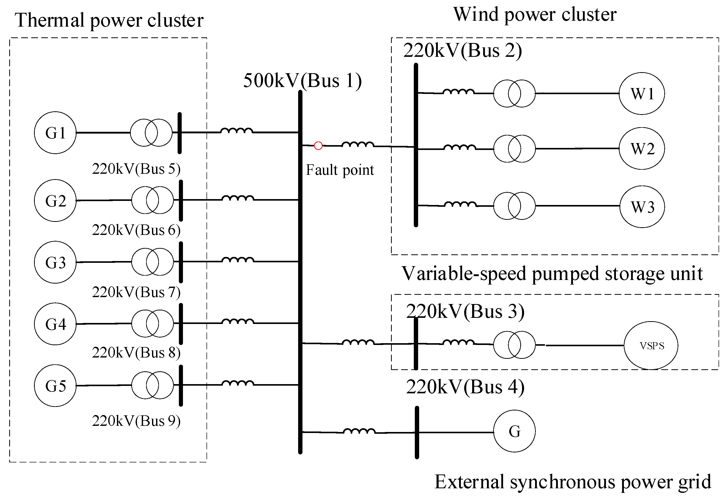
At present, regional power grids are closely interconnected. When a short-circuit grounding fault occurs on the 500-kilovolt power transmission line, the number of wind turbine units in the fault state that enter the low-voltage ride-through mode increases. In many wind turbines of large-scale new energy bases, the transient voltage drop may trigger the low-voltage ride-through protection, resulting in a sudden large shortage of active power. Before the wind turbine output recovers, the regional power grid with a high proportion of new energy sources has the risk of low-frequency oscillation. With the continuous large-scale integration of new energy into the power grid, the scale of wind power entering the low-voltage ride-through state under faults increases, and the system frequency will further decrease, posing the risk of triggering low-frequency load shedding actions. Usually, traditional methods mainly adopt the construction of backup channels between regional power grids to address this issue. However, this method has a long construction period. As shown in 
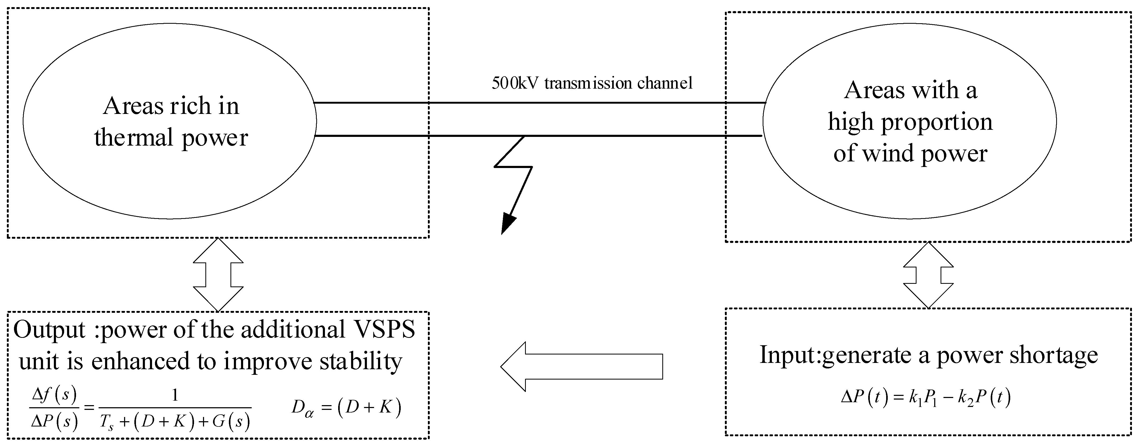
Figure 1, Region 1 is a region rich in thermal power, and Region 2 is a high-proportion wind power area with wind power clusters for external transmission. A large-scale and high-capacity energy storage device is urgently needed to intervene in the above situation to enhance the stability of the regional power system. The VSPS unit is one of the most effective methods. Figure 1 shows the schematic diagram of transmission channel faults in the regions rich in thermal power and the high proportion of wind power areas. Take Equation (1), namely the power difference, as the input value into the system, and construct the frequency response model considering the power difference and containing the VSPS unit at the output, which is expressed by Equations (2) and (3).
The power shortfall caused by low-voltage ride-through of wind power clusters in areas with a high proportion of wind power can be expressed as Equation (1).
Δ P t = k 1 P 1 k 2 P t
Let the power shortage caused during the fault and the wind power range of the high-proportion wind power transmission area affected by the fault be k1, and the active power recovery rate of the recovery area be k2. At the same time, set the total wind power output before the fault as P1, and the power shortage caused by the low-voltage ride-through of wind power as Δ P . The relationship between the power shortage caused by the low-voltage ride-through of wind power and time is Δ P t .
Meanwhile, referring to the use of the standard transfer function to describe the equivalent dynamic model of the mixed prime mover and governor, the system damping of the generator damping D and the frequency coefficient K in the areas rich in thermal power and the areas with a high proportion of wind power are combined, and the overall transfer function relationship of the system is obtained as shown in Equation (2); the new damping coefficient is D α , as shown in Equation (3).
Δ f s Δ P s = 1 T s + D + K + G s
D α = D + K
Among them, G s represents the system transfer function, Δ P s represents the perturbation power transfer function, and Δ f s represents the perturbation frequency transfer function. D α is the new damping coefficient.
Furthermore, a new general model of SFR (system frequency response) was obtained. The frequency response of the power system mentioned in this paper refers to the change in the system frequency after the 500 kV connection line of the regional power system is disturbed by active power, as shown in Figure 1. The process is shown in which the generator set in the system adjusts its output power through the governor and frequency regulation device to restore the system frequency to close to the rated value [36,37,38,39,40]. In this model, it is no longer confined to specific prime mover and governor models, and thus is more applicable to the frequency response model of power systems containing thermal power units, VSPS units, and wind turbine clusters.

3. System Power Response Analysis of Variable-Speed Pumped Storage Units

3.1. Analysis of Operating Range of Variable-Speed Pumped Storage Units

Referring to the earliest VSPS units put into operation in China, all the units discussed below are based on 300 MW. Theoretically, variable-speed motors can achieve rapid regulation of active power. However, in practical applications, various constraints need to be taken into account. When studying the induced capacity of AC excitation, the output capacity curve of the synchronous motor can be used as a reference. Since the temperature rise in the armature winding and the excitation winding is closely related to the winding itself, the structure, and the layout, in this study, the rated current of the stator winding and the excitation current can be considered as boundary conditions to study whether the system is stable when reactive power is controlled in both directions. The regulation limitations of active power and reactive power of variable-speed pumped storage units mainly manifest in the limitations of the input and output power of the turbine, the limitation of the stator current of the AC excitation motor itself, the rotor current limitation, and the rotor voltage limitation.
Ird and irq are the components of the rotor current ir in the d-axis and q-axis. Therefore, the sum of their squares is the amplitude of the rotor current. After simplification, we get Equation (4):
P 2 + ( Q 3 2 L m u s L s i m s ) 2 = 3 2 L m u s L s u r R r 2
P represents the maximum active power that can be generated, Q represents the maximum reactive power that can be generated, Lm represents the mutual inductance between the stator and rotor, Ls represents the srotor inductance, us represents the srotor side voltage, ims represents the current converted from the stator to the rotor side, ur represents the rotor side voltage, and Rr represents the internal resistance.
This indicates that the operating range of the stator power of the variable-speed unit is a circle with the rotor current as the constraint, whose center is on the Q-axis. Moreover, the center and radius are related to the stator voltage. When the unit is out of phase, the stator voltage is lower than the rated value, and the center and radius of the power circle will shrink towards the coordinate origin. At the same time, the maximum rotor voltage limit should be considered. When the rotor speed or rotor voltage changes, the motor power curve will change. The rotor voltage limit is as follows.
u r u 2 max = m U d c 6
In the Equation (5), m represents the modulation degree. When the rotor voltage reaches its maximum value u2max, m takes the maximum value of 1. The operating limits mainly occur in the sub-synchronous power generation and super-synchronous motor operation states, which are determined by the slip rate of the variable-speed pumped storage unit operation.

3.2. Analysis of the Reactive Power Capacity of Variable-Speed Pumped Storage Units

When the stator voltage is constant, the rated capacity (apparent power) of the unit determines the allowable value of the stator current. In the two-dimensional power-Q diagram, the limit line of the stator current is a circle centered at the origin. Based on the above analysis, the schematic diagram of the power regulation capability of the variable-speed pumped storage unit is shown in Figure 2. The drawing of Figure 2 is derived from Equations (4) and (5), which are, respectively, explained by setting different stator currents and rotor currents.
As shown in Figure 2, which is the power regulation capability diagram of the variable-speed pumped storage generator set, since the variable-speed pumped storage generator set has the bidirectional regulation capability of active power and reactive power, O1 represents the stator current constraint circle, O1A is the radius of the stator current constraint circle, O2 is the rotor current constraint circle, and O2B is the radius of the rotor current constraint circle. Circle O3 is the rotor voltage constraint circle, and O3C is the radius of the rotor voltage constraint circle, mainly determined by the slip rate. When the slip rate S < 0, a rotor voltage constraint circle 1, 2, 3 centered at O3 is formed; when the slip rate S > 0, rotor voltage constraint circles 4, 5, 6 centered at O4 are formed, where O4D is the radius of the rotor voltage constraint circle. From Figure 2, it can be seen that the variable-speed pumped storage generator set has the bidirectional regulation capability of active and reactive power. This paper mainly discusses the reactive power priority support of VSPS in the scenario of the low-voltage ride-through of large-scale wind power, and supports the system with the priority regulation value of reactive power adjustment. If the slip rate is positive, the reactive power regulation capability mainly manifests in the working state on the right plane; within the range formed by the combined restrictions proposed in this paper, it is possible to achieve simultaneous regulation of active and reactive power under reactive power priority control, and it can be found that as the depth of the reactive power regulation of VSPS increases, the regulation of active power of VSPS will also be continuously limited and reduced with the change in the slip rate.

4. VSPS Dual-Channel Power Control Strategy Construction and Stability Analysis

4.1. Construction of Overall Power Control for VSPS

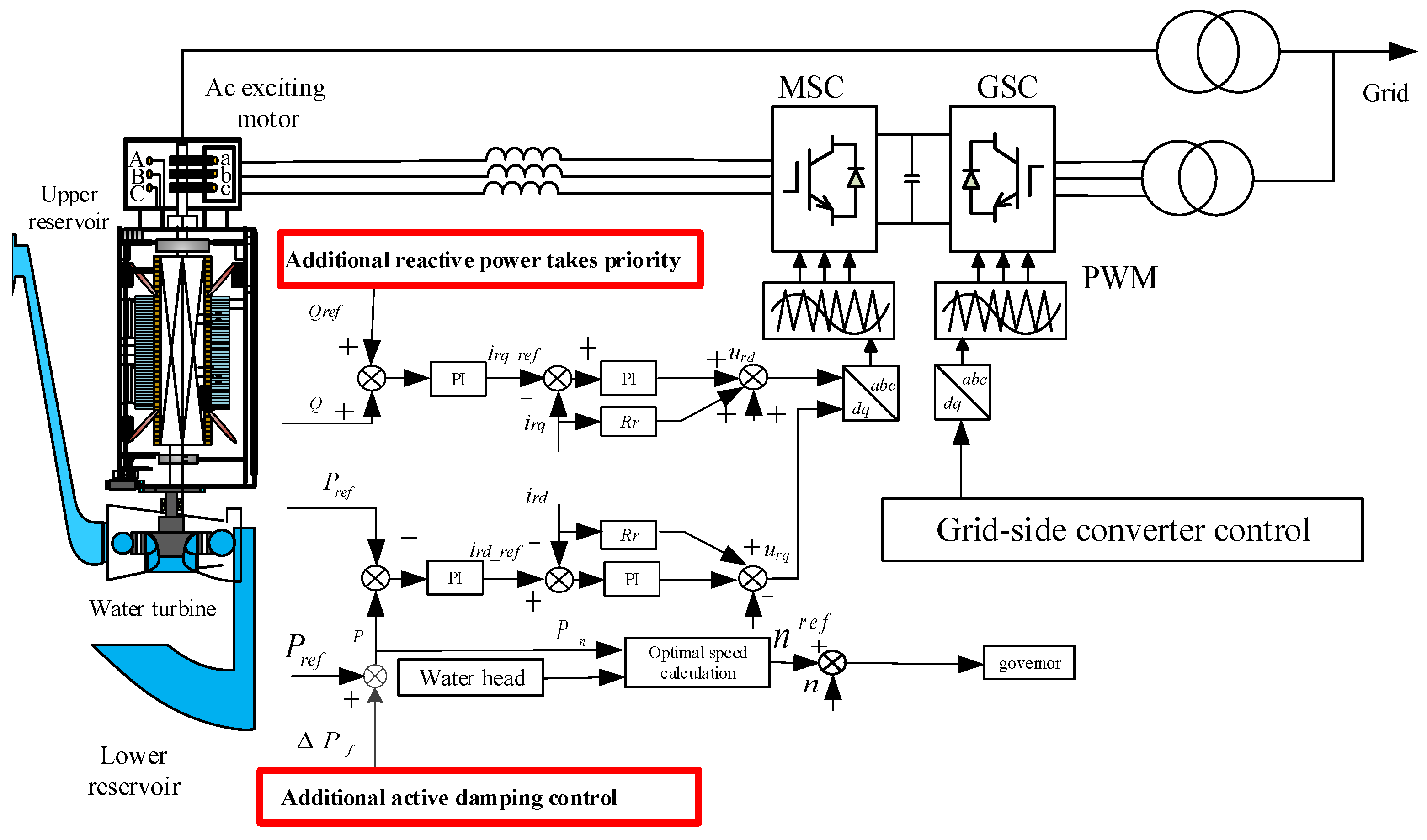
The VSPS unit is mainly composed of the hydraulic part, the mechanical part, and the electrical part. The hydraulic part mainly includes the upper reservoir, the lower reservoir, the water diversion pipe, etc. The mechanical part mainly includes the reversible pump turbine, the hydraulic ball valve, etc. The electrical part mainly includes the AC excitation motor, the converter and its control part, etc. This article mainly discusses the power control part. The power control of variable-speed pumped storage units is mainly divided into two parts: governor control and converter control. The governor control mainly manifests in the mechanical torque control of the water turbine generator, and the response speed to instantaneous power shortage is relatively slow. The converter control mainly manifests in the power electronic control part of the doubly fed converter, and through the AC excitation control, it performs decoupled control on the active and reactive power of the unit and the inertia response. Among them, the control objective of the grid-side converter is to maintain the stability of the DC voltage. Since the construction of the VSPS dual-channel power control strategy proposed in this paper mainly focuses on the unit measurement converter, the control part of the grid-side converter will not be further elaborated. The unit measurement converter consists of two parts: internal current control and external power control. It achieves power control by controlling the amplitude, frequency, and phase of the rotor current, while meeting the requirements of the external power system for the rapid support of active and reactive power. VSPS dual-channel power control refers to not merely controlling the active or reactive power output by the unit, but simultaneously generating both active and reactive power based on the reactive power output limit of the unit. Figure 3 shows the overall control idea of VSPS in this paper and the construction idea of the dual-channel power control strategy.
Considering the control objective of the converter on the machine side, as well as the servo relationship between the rotor voltage on the machine side and the operation of the unit, the stator voltage-oriented vector control strategy is selected for the converter on the machine side. The synchronous rotating coordinate system selects the d-axis direction as the stator flux direction, and the stator resistance is ignored. In the steady state, the stator flux is a constant value, and the lagging voltage is 90°. The AC excitation motor model can be obtained as follows from Equations (6) and (7):
u s d = u s u s q = 0
Ψ s d = 0 Ψ s q = u s d ω s
usd represents the d-axis voltage on the stator side, usq represents the q-axis voltage on the srotor side, and us represents the voltage on the stator side.
Ψ s d represents the d-axis flux linkage on the stator side, Ψ s q represents the q-axis flux linkage on the stator side, and ω s represents the angular velocity on the stator side.
In the current inner loop control, the rotor current cannot be directly controlled, so it is necessary to achieve rotor current control indirectly through a medium. Through the converter on the machine side, the relationship between the rotor current and the excitation voltage can obtain the strategy to control the excitation voltage and thereby control the rotor current, to establish a connection between the stator and rotor magnetic fluxes. Ignoring the transient state of the stator magnetic flux, the relationship between the voltage and the current can be derived from Equation (8):
u r d = R r i r d + i r d s ω s δ i r q s ω s L m L s Ψ s q u r q = R r i r q + i r q + s ω s δ i r d + s ω s L m L s Ψ s d
ird represents the current of the rotor’s d-axis, irq represents the current of the rotor’s q-axis, urd represents the voltage of the rotor’s d-axis, and urq represents the voltage of the rotor’s q-axis. Other meanings are the same as those mentioned in the previous formula. By observing Equation (8), it can be found that both voltage equations contain the d-axis current and q-axis current. This coupling phenomenon hinders the purpose of achieving separate control of the dq components. To solve the coupling problem and achieve decoupling control, feedforward voltage compensation needs to be introduced to correct the control. Finally, the current inner loop control is obtained, the outer loop of the converter on the machine side is active and reactive power control, and after PI control, the reference value of the inner loop current is obtained, which can represent the outer loop control as shown in Equation (9),
i s d = k p + k i s P P i s q = k p + k i s Q Q
isd represents the d-axis current on the machine side, isq represents the d-axis current on the network side, kp represents the proportionality coefficient, and ki represents the integration coefficient.

4.2. VSPS Reactive Power Priority Control Strategy

During the asynchronous operation of synchronous generators, numerous hazards can be triggered. When synchronous generators are operating in asynchronous mode, compared to the lagging mode, their excitation current significantly decreases, and the generator’s electromotive force also drops accordingly. The AC excitation variable-speed pumped storage units demonstrate strong asynchronous operation capabilities. The magnitude and relative position of the excitation magnetic field of the AC excitation generator are determined by the size and frequency of the excitation voltage, as well as their phase relationship with the stator voltage in the synchronous shaft system. By applying appropriate control strategies, the active power and reactive power output of the generator can be independently regulated, and the regulation of reactive power is a purely electromagnetic process with a very short transition period. Due to the increased freedom of excitation control, the position of the excitation magnetic field relative to the rotor can be effectively controlled. To provide reactive power support for the system during a grid voltage drop, not only does the unit need to be able to operate in parallel for a certain period, but it also needs to have the ability to provide dynamic reactive power support to the grid during faults and quickly return to normal operation after the grid fault is cleared. According to the principle of variable-speed pumped storage units and the principle of AC excitation converters, during a grid voltage drop, two reactive power sources can provide reactive power support for the grid: the AC excitation grid-side converter and the pumped storage unit itself. On one hand, the AC excitation grid-side converter can be controlled to operate in the “SVG(Static Var Generator)” mode during the voltage drop, but this requirement will increase the capacity of the AC excitation equipment; on the other hand, through the AC excitation rotor-side converter control, the variable-speed motor can be in the “strong excitation” state, output reactive power, and help restore the grid voltage.
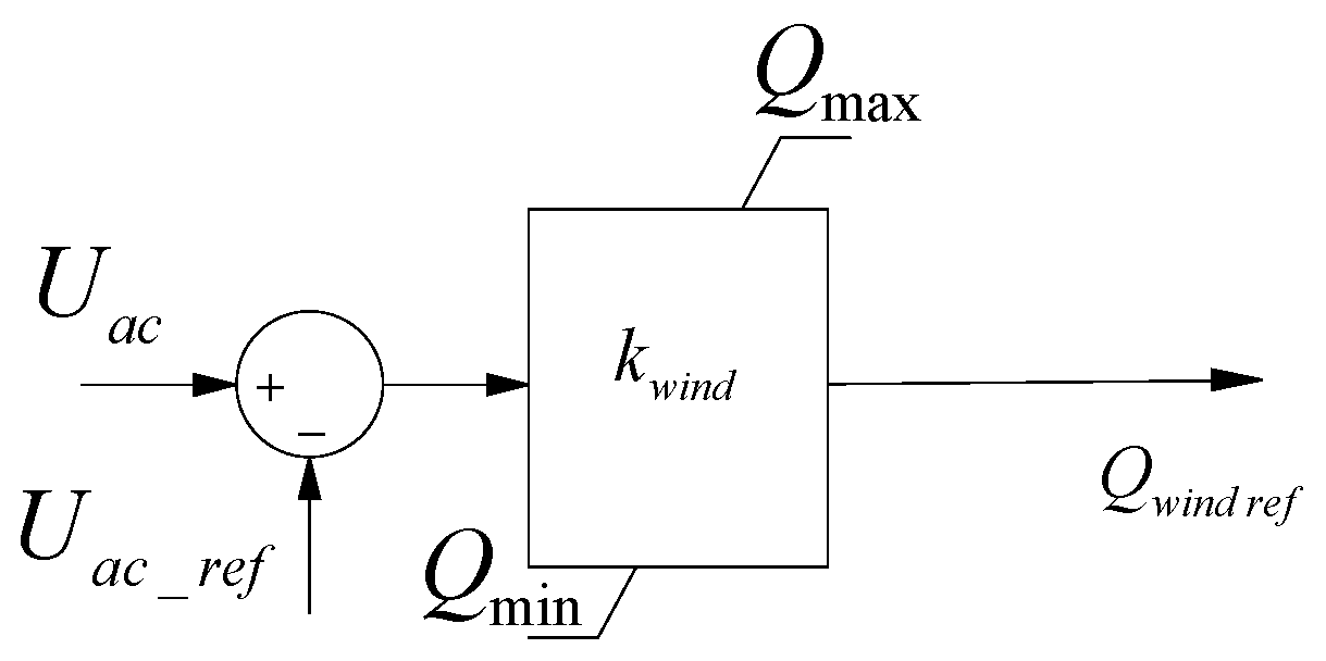
Since it is unreliable to transmit voltage change information to the control signal of the pumped storage through long-distance communication means, the receiving end converter station needs to accurately convert the information representing the wind farm cluster’s output side into the reactive power information required by the pumped storage. The essence of the reactive power priority support control strategy is reactive power–voltage drop control, and its control method can be expressed as Equation (10),
Q w i n d   r e f = K w i n d U a c U a c _ r e f + Q w i n d
where Kwind is the coupling coefficient between the output voltage of the wind farm cluster and the reactive power output by the VSPS machine-side converter. The reactive power priority control mode based on the Q-v curve proposed in this paper is shown in Figure 4. Figure 5 is the active power regulation system of reactive power priority control. The active power output must refer to the maximum and minimum output of reactive power in actual operation. The reference value of active power in Figure 5 points to the power operation range calculated in Figure 2.
K w i n d = Q max Q min Δ U max
The construction of the VSPS Reactive Power Priority Control Strategy first depends on the voltage sag signal of the AC transmission line, and refers to the previously calculated instantaneous maximum reactive power range that the VSPS can emit and the Q-v relationship. Finally, the reactive power priority control of the VSPS unit is obtained. The specific control idea is reflected in Figure 4. Meanwhile, the VSPS unit has dual-channel power output capability. However, the maximum value of the active power output of the VSPS is limited by the reactive power output range of the VSPS. To prioritize the stability of the voltage, reactive power priority control is adopted. The specific control scheme is described in Figure 5. And the relevant parameters are the same as those of Equations (10) and (11).

4.3. Construct Additional Damping Control for VSPS

Variable-speed pumped storage operates to dampen small power fluctuations by controlling the AC excitation. Currently, a virtual inertia frequency modulation control based on rotor kinetic energy is considered, which includes additional control links for the frequency change rate and frequency deviation. An additional frequency–power outer loop is added to the doubly fed generator control system, enabling the variable-speed pumped storage unit to have frequency response capabilities. The df/dt (differential) link is representative of the frequency change rate, and the Δf proportional link is representative of the dynamic frequency deviation. This additional frequency–power outer loop can rapidly change the output power of the unit, providing dynamic support for the system power.
The relationship between the grid frequency variation and power imbalance is reflected in Equation (12).
J ω s 2 S N d f d t + D Δ f = P G P l o a d = Δ P f
PG is the output power of a conventional synchronous generator, and Δf is the frequency change amount. D is the drop control coefficient. For grid frequency fluctuations, the relationship with frequency can be formed by the superposition of the inertia loop and the drop loop.
The unit on the variable-speed pumped storage side can obtain the change information of the receiving-end AC grid. Therefore, the power auxiliary control of the variable-speed pumped storage unit needs to respond to the fluctuations of the receiving end by responding to the frequency change information ∆ω received from the sending-end converter station, providing power support. An active damping controller is introduced to suppress the system’s low-frequency oscillation when a low-frequency oscillation occurs. SN represents the rated capacity of the VSPS unit. The specific relationship is reflected in Equation (13)
P r e f = P r e f + P a d d = P r e f + k w d ω s d t
where kw is the coupling coefficient of variable-speed pumped storage, Pref is the active power command of the variable-speed pumped storage unit, and Padd reflects the additional power increment due to frequency change. The mentioned additional damping control mainly generates power compensation in the form of active damping control, mainly including the gain, phase compensation, and voltage-limiting part, and is combined with power compensation control considering frequency compensation. The construction of the control idea is shown as Equation (14).
G ( s ) = K v p s T v p 1 + s T v p 1 + s T a p 1 + s T b p m
Among them, the damping controller first collects the grid frequency, and then obtains the power after the amplitude correction, filtering link, phase correction, and limiting link, compensating for the change values. Kvp is the amplitude correction parameter, Tvp is the oscillation suppression time constant, Tap and Tbp are the phase correction parameters, m is the correction order, and s is the Laplacian operator. Figure 6 shows the VSPS active power control considering active damping control.
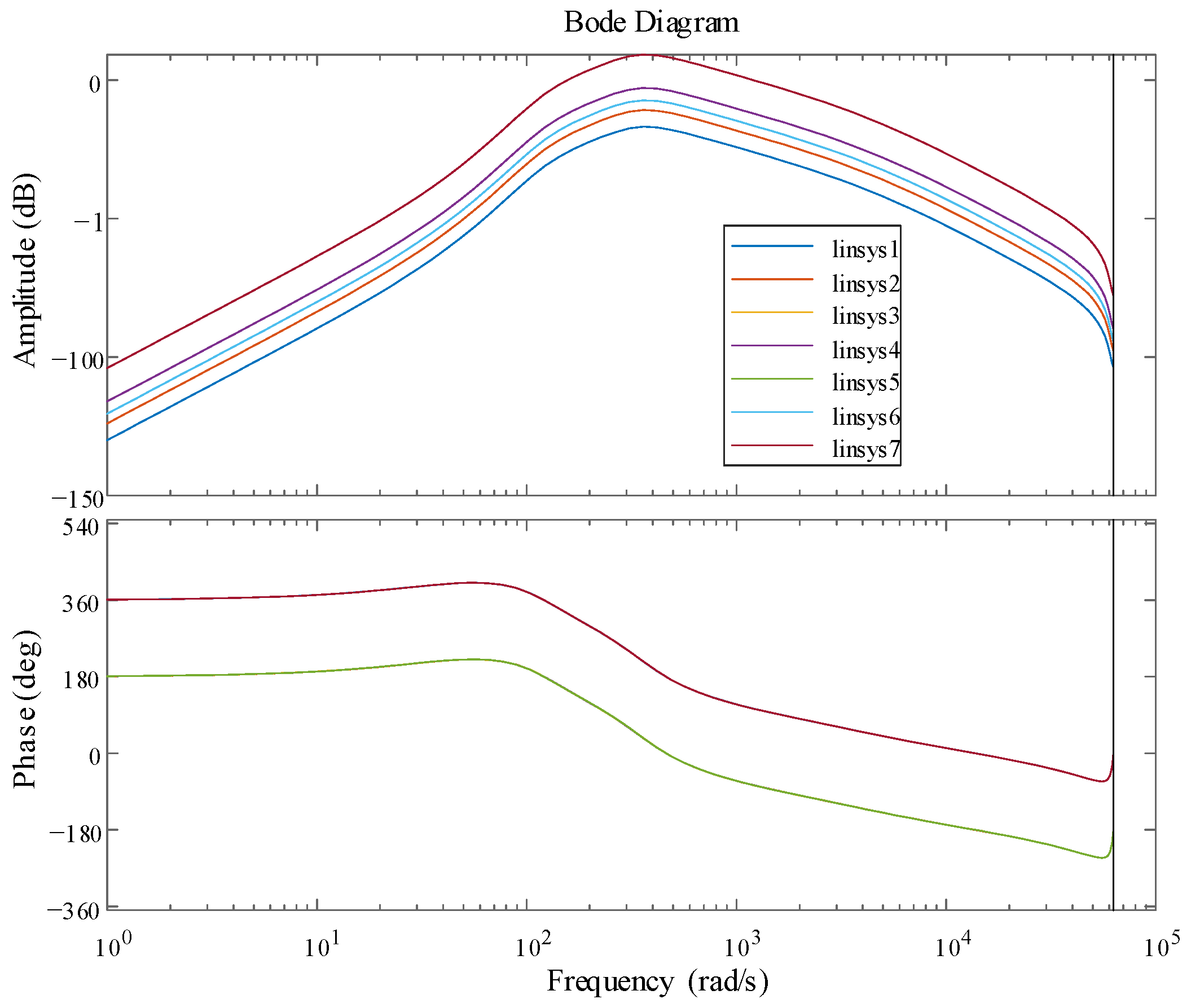
To verify the stability of the VSPS active control with additional damping in the overall system control, the Bode plot and Nichols plot of the additional damping control system were analyzed. Starting from the gain coefficient kvp in Figure 6 of the additional damping control, the system Bode plots under different gain coefficients were analyzed, and the stability of the VSPS active control with additional damping under different frequencies and phases was analyzed. Seven different gain coefficients were set for analysis, among which the gain coefficient kvp of curve linsys1 was 0.005, the gain coefficient kvp of curve linsys2 was 0.010, the gain coefficient kvp of curve linsys3 was 0.015, the gain coefficient kvp of curve linsys4 was 0.025, the gain coefficient kvp of curve linsys5 was 0.100, the gain coefficient kvp of curve linsys6 was −0.015, and the gain coefficient kvp of curve linsys7 was −0.100. The Bode plot considering the additional damping control is shown in Figure 7.
As shown in Figure 7, when the gain coefficient is positive, the peak amplitude (dB) gradually increases at different frequencies. The absolute values of curves linsys3 and linsys6 are the same, and the amplitude (dB) characteristics overlap. The absolute values of curves linsys4 and linsys7 are also the same, and the amplitude (dB) characteristics also overlap. Therefore, the amplitude (dB) characteristics are independent of the gain’s positive or negative sign. The gain coefficient does not affect the curves linsys1, 2, 3, 4, and 5, which overlap, and the curves linsys6 and 7 overlap. The phase (deg) characteristics are independent of the absolute value of the gain coefficient and only related to the positive or negative sign of the gain coefficient. To distinguish the overlapping curves, an analysis of the Nichols plot considering additional damping control is conducted, as shown in Figure 8.
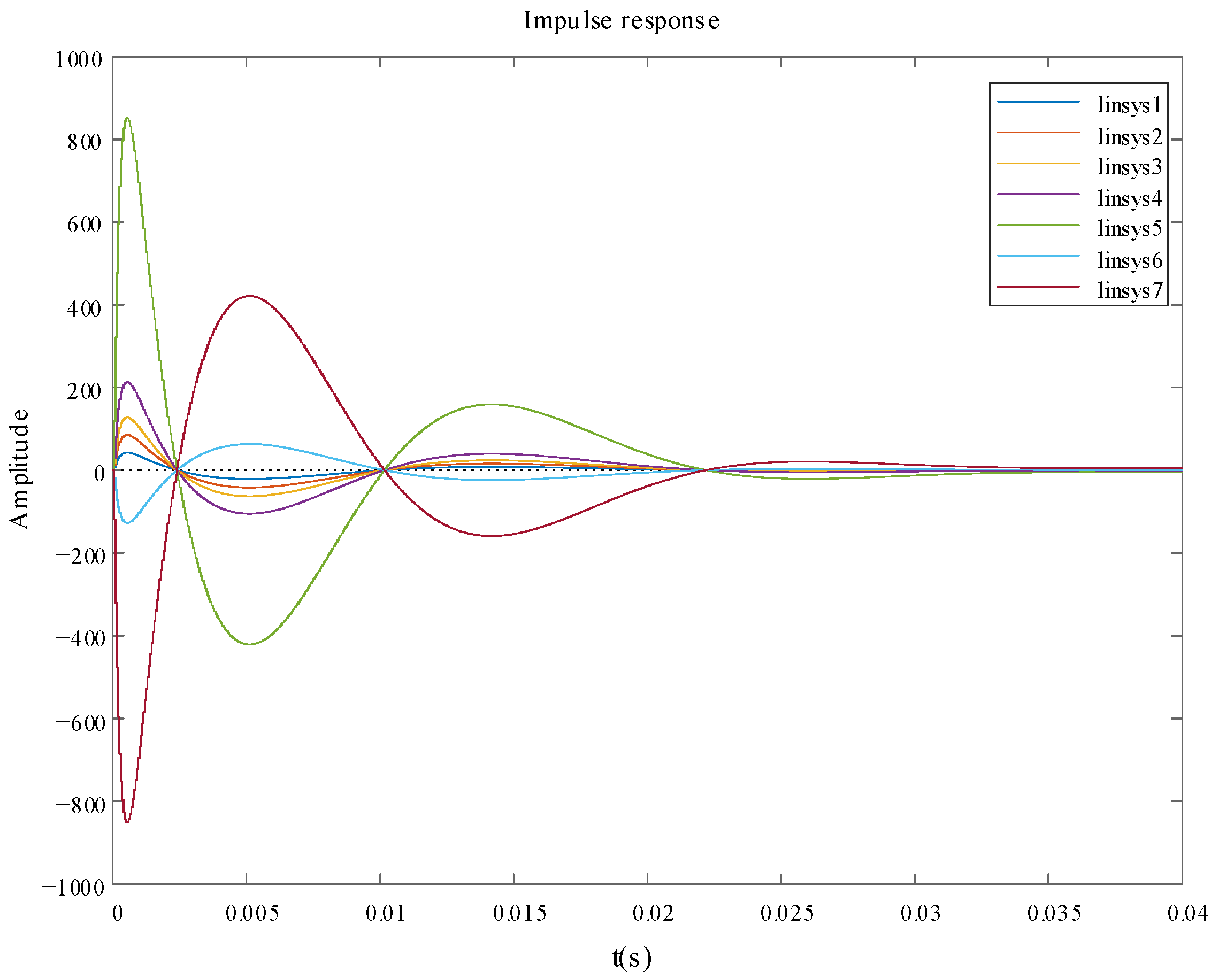
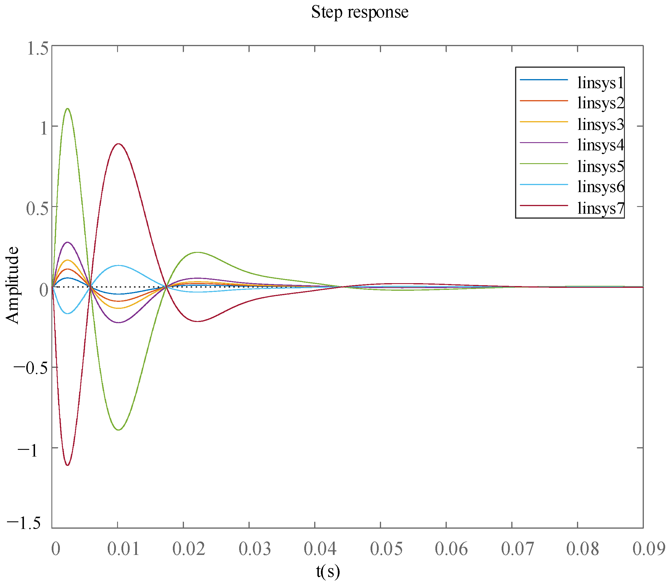
The Nichols plot curves under different gain coefficients were obtained, and all the curves in the Bode plot were separated. Except for linsys4 and linsys7, where the open-loop gain (dB) exceeded 0, all other gain coefficients were within 0. To analyze the response rate of the additional damping control, the step response and impulse response under different gain coefficients were analyzed. The coefficients of linsys1-7 were the same as those mentioned above. Figure 9 shows the impulse response considering additional damping control, and Figure 10 shows the step response considering additional damping control.
Based on the impulse response diagram considering the additional damping control as shown in Figure 9, under different gain coefficients of the additional damping control, except for the initial state of the impulse response having a large fluctuation, it enters a stable state after 0.03 s. According to Figure 10, considering the additional damping control, except for the initial state of the step response having a large fluctuation, it enters a stable state after 0.07 s.

5. Case Analysis

5.1. Simulation Calculation Background

This paper takes a certain new energy base in Northeast China, which is supported by an actual project, as the case study. Its equivalent topological structure is shown in Figure 11. Among them, G1, G2, G3, G4, and G5 are thermal power clusters, which are connected to 500 kV Bus 1 through 220 kV Bus 5-9. The installed capacity of the thermal power units is all 600 MW. W1, W2, and W3 are wind power clusters, which are further connected to 500 kV Bus 1 through 220 kV bus 2. The full-load power of wind power cluster 1 (W1) is 800 MW, that of wind power cluster 2 (W2) is 1300 MW, and that of wind power cluster 3 (W3) is 1500 MW. The VSPS is connected to the 500 kV Bus 1 through the 220 kV bus 3. Referring to the successful grid-connected Zhangbei variable-frequency pumped storage unit in China, it is set at 300 MW. The subsequent part of this paper mainly adopts MATLAB/Simulink software for simulation analysis. The version number of MATLAB/Simulink software is 2022a.
This example is set in Figure 11. The specific power of each unit is as follows. Table 1 shows the installed capacity of the unit.

5.2. Analysis of Wind Power Side Response

This paper intends to conduct a simulation verification analysis based on the most severe fault scenario. If a three-phase short-circuit fault occurs at the outlet of the wind power cluster convergence line, the fault point is marked in Figure 11; to prevent the power angle instability of the generating units, the stability control system will act to cut off the thermal power-generating units, and the thermal power units will be disconnected while the nearby wind power enters a low-power operation state. Condition 1 refers to when VSPS was not connected, and condition 2 refers to when VSPS was connected and dual-channel power control was in progress. In condition 1, a fault occurs again within 10 s and is cleared at 10.5 s, with the VSPS unit disconnected. An amount of 500 kV is the reference value of the mentioned voltage. When oscillation actually occurs, it will occur around 500 kV. The reference values of active power P, reactive power Q, mechanical torque, and electromagnetic torque depend on the actual output power. When power oscillation occurs again, the power oscillates near the actual power. The unit value is taken to improve the adaptability of different power outputs. Figure 12 shows the three-phase voltage, three-phase current, active power, and reactive power of the 500-kilovolt connection line.
From Figure 12, it can be seen that the power transmission of the power network connection system stops from 10 s to 10.5 s. After 10.5 s, the curves of the three-phase voltage, three-phase current, active power, and reactive power of the 500 kV connection line will exhibit severe power oscillation phenomena. If this power oscillation pattern continues to extend to other areas, it will have a significant impact on the stability of the regional power system. Meanwhile, as shown in Figure 13, the voltage at the connection point of the wind power cluster and the electromagnetic torque of the wind turbine are simulated and analyzed.
As can be seen from Figure 13, the voltage at the connection point of the wind power cluster drops from 10 s to 10.5 s, and after 10.5 s, there are varying degrees of oscillations in the voltage at the connection point of the wind power cluster and the electromagnetic torque of the wind turbines. There is a possibility that more severe oscillations may occur after 13 s.
Working condition 2 repeatedly failed at 10 s, and the fault was cleared at 10.5 s. In working condition 2, VSPS was connected, and dual-channel power control was carried out. Among them, Figure 14 shows the three-phase voltage, three-phase current, and active power and reactive power of the 500 kV connection line when VSPS was connected and dual-channel power control was in progress.
From Figure 14, it can be seen that the power transmission of the power network connection system stops from 10 s to 10.5 s. Considering the communication delay between the units and the control delay of the VSPS units, the curves of the three-phase voltage, three-phase current, active power, and reactive power of the 500 kV connection line after 10.5 s introduce dual-channel power control under the control of VSPS. It can be observed that the system power oscillates for 0.6 s and then returns to the normal operating state, improving the overall stability of the system. As shown in Figure 15, the voltage at the connection point of the wind power cluster and the electromagnetic torque of the wind turbine units are also simulated and analyzed.
As can be seen from Figure 15, the voltage at the connection point of the wind turbine cluster drops from 10 s to 10.5 s, and after 10.5 s, there are varying degrees of oscillation in the voltage at the connection point of the wind turbine cluster and the electromagnetic torque of the wind turbines. After the oscillation at 0.6 s, it returns to the normal operating state, enhancing the stability of the wind turbine cluster grid connection system.

5.3. Analysis of VSPS Side Response

Meanwhile, as shown in Figure 16, the rotor speed, active power output, and reactive power output curves of the VSPS system are analyzed.
From Figure 16, it can be seen that a fault occurred in the power network connection system from 10 s to 10.5 s. Considering the communication delay between the units and the control delay of the VSPS units, the VSPS units issued active power and reactive power at 10.5 s. The active power increased from 0.2 p.u. to 0.35 p.u., and the reactive power increased from 0.1 p.u. to 0.25 p.u. Both the active power and reactive power were adjusted within 0.4 s to support the system. Meanwhile, the rotor speed of the VSPS units reduced from 1.24 p.u. to 1.04 p.u., and the rotor quickly released energy. To analyze the stability of the VSPS units under control, as shown in Figure 17, the single-phase current curves on the unit side and the single-phase current curves on the grid side of the VSPS units were analyzed.
From Figure 17, it can be seen that a fault occurred in the power network connection system from 10 s to 10.5 s. Considering the communication delay between the units and the control delay of the VSPS unit, the curves of the single-phase current on the machine side and single-phase current on the grid side of the VSPS unit changed at 10.5 s. The value of the machine-side current Ir increased, and the phase of the grid-side current Ig increased, corresponding to the power curve in Figure 16. At the same time, as shown in Figure 18, the mechanical torque and electromagnetic torque of the VSPS are analyzed.
From Figure 18, it can be seen that the power network connection system failed in the 10 s to 10.5 s period. Considering the communication delay between the units and the VSPS unit control delay, the mechanical torque decreased, indicating that the VSPS was operating in the power generation state. The absolute values of the mechanical torque Tm and the electromagnetic torque Tem increased, corresponding to the rotor speed in Figure 16. The electromagnetic torque completed the power regulation within 0.4 s, corresponding to the active power change in Figure 16.
Based on the analysis of a certain new energy base in Northeast China in this section, the VSPS dual-channel energy control proposed in this paper improves the stability of the regional power grid and restores the asymmetric power system after the fault to a symmetrical power system.

6. Conclusions

This paper investigates the rapid dual support capability of variable-speed pumped storage (VSPS) units in high-proportion new energy power systems under single short-circuit fault conditions. A VSPS power dual-channel energy control model is proposed to compensate for the deficiencies in the fault ride-through and low-frequency oscillation suppression capabilities of wind turbine units. The bidirectional regulation ability and depth of the active and reactive power, as well as the reactive power leading capability of the VSPS units, are analyzed. A large-scale rapid active and reactive power control strategy prioritizing reactive power is proposed, and VSPS additional damping control is constructed to suppress regional power grid oscillations. Tests based on a new energy base in Northeast China show that the asymmetric power system can be restored to a symmetrical and stable state within 0.5s after a fault, preventing system power oscillation. Future work may focus on further optimizing these strategies and exploring their applications in more complex power system scenarios.

Author Contributions

W.C.: conceptualization; data curation; formal analysis; validation; writing—original draft; and writing—review and editing; J.X.: conceptualization; data curation; formal analysis; funding acquisition; and writing—review and editing. All authors have read and agreed to the published version of the manuscript.

Funding

This work was supported in part by the National Natural Science Foundation of China (51777130).

Data Availability Statement

The data that support the findings of this study are available from the corresponding author upon reasonable request.

Acknowledgments

This article thanks the editorial department of the publisher and the School of Electrical Engineering at Shenyang University of Technology for their strong support.

Conflicts of Interest

The authors declare no conflicts of interest.

References

  1. Xu, Z.; Liu, Q.; Xu, L.; Mo, L.; Zhang, Y.; Zhang, X. Optimal Dispatching Rules for Peak Shaving of Cascaded Hydropower Stations in Response to Large-Scale New Energy Integration. Processes 2025, 13, 612. [Google Scholar] [CrossRef]
  2. Wang, Z.; Lv, X.; Li, D.; Han, S. Integrated production simulation of renewable energy and transportation consumption. J. Phys. Conf. Ser. 2024, 2782, 012016. [Google Scholar] [CrossRef]
  3. Dunn, L.N.; Kavvada, I.; Badoual, M.D.; Moura, S.J. Bayesian hierarchical methods for modeling electrical grid component failures. Electr. Power Syst. Res. 2020, 189, 106789. [Google Scholar] [CrossRef]
  4. Qin, L.J.; Wu, X.T. Research on Intelligent Auxiliary Decision-Making System for Regional Power Grid Faults. Adv. Mater. Res. 2014, 329, 1254–1257. [Google Scholar] [CrossRef]
  5. Yang, M.; Han, C.; Zhang, W.; Fang, G.; Jia, Y. A short-term power prediction method based on numerical weather prediction correction and the fusion of adaptive spatiotemporal graph feature information for wind farm clusters. Expert Syst. Appl. 2025, 274, 126979. [Google Scholar] [CrossRef]
  6. Van Binsbergen, D.; Verma, A.; Nejad, A.; Helsen, J. Modeling of rain-induced erosion of wind turbine blades within an offshore wind cluster. J. Phys. Conf. Ser. 2024, 2875, 012040. [Google Scholar] [CrossRef]
  7. Parameswari, G.A.; Arunsankar, G. Hybrid approach based on optimal low-voltage ride-through capability in DFIG-based wind energy systems. Energy 2025, 324, 135541. [Google Scholar] [CrossRef]
  8. Liu, D.; Ma, X.; Wang, Z.; Yang, Y.; Wang, J. Crowbar-Less Low-Voltage Ride-Through Control Strategy for Full-Size Converter-Based Variable-Speed Pumped Storage Units in Generation Mode. Electronics 2025, 14, 1411. [Google Scholar] [CrossRef]
  9. Yin, J.; Chen, Z.; Qian, W. A Virtual Synchronous Generator Low-Voltage Ride-Through Control Strategy Considering Complex Grid Faults. Appl. Sci. 2025, 15, 1920. [Google Scholar] [CrossRef]
  10. Marri, M.I.; Malik, N.U.R.; Masud, M.; Jumani, T.A.; Khidrani, A.U.; Shahid, Z. Reinforcement Learning-Based Current Compensation for Brushless Doubly Fed Induction Generators Under Transient- and Low-Voltage Ride-Through Faults. Energies 2025, 18, 881. [Google Scholar] [CrossRef]
  11. Li, B.; Wang, Y. Enhanced Low-Voltage Ride-Through Scheme for Grid-Forming Converters Considering Current Limitation and Transient Stability Simultaneously. Sustainability 2025, 17, 1428. [Google Scholar] [CrossRef]
  12. Loulijat, A.; Hilali, A.; Makhad, M.; Chojaa, H.; Ababssi, N.; Mossa, M.A. Low-voltage ride-through capability of DFIG-based WECS improved by nonlinear backstepping controller synthesized in novel power state model. e-Prime 2025, 11, 100864. [Google Scholar] [CrossRef]
  13. International Hydropower Association. 2023 World Hydropower Outlook; International Hydropower Association: London, UK, 2023. [Google Scholar]
  14. Toufani, P.; Nadar, E.; Kocaman, A.S. Operational benefit of transforming cascade hydropower stations into pumped hydro energy storage systems. J. Energy Storage 2022, 51, 104444. [Google Scholar] [CrossRef]
  15. Blakers, A.; Stocks, M.; Lu, B.; Cheng, C. A review of pumped hydro energy storage. Prog. Energy 2021, 3, 022003. [Google Scholar] [CrossRef]
  16. Gustavsson, P.Z. Development of an Investment Model for Pumped Storage Hydropower; Uppsala University: Uppsala, Sweden, 2023. [Google Scholar]
  17. Zhao, Z.; Chen, D.; Li, J.; Wei, S.; Sun, H. Flexibility assessment of regional energy systems considering five types of pumped storage with different operational characteristics. Proc. CSEE 2023, 43, 7103–7115. (In Chinese) [Google Scholar]
  18. Xia, S.; Ding, Z.; Du, T.; Zhang, D.; Shahidehpour, M.; Ding, T. Multitime scale coordinated scheduling for the combined system of wind power, photovoltaic, thermal generator, hydropumped storage, and batteries. IEEE Trans. Ind. Appl. 2020, 56, 2227–2237. [Google Scholar] [CrossRef]
  19. Chen, Y.; Deng, C.; Liu, Y.; Xu, Z.; Li, D.; Chen, M.; Peng, P. Electromechanical transient modelling and active power-frequency coupling characteristics of doubly-fed variable speed pumped storage under pumping mode. Proc. CSEE 2022, 42, 942–957. [Google Scholar]
  20. Peng, Y.; Wang, X.; Liu, D.; Li, Y.; Yang, Y.; Xiong, Y.; Chen, M.; Zhong, H. Comparative research on the dispatching operation of hydro-wind-solar-storage complementary system considering configurations with hybrid and pure pumped-storage hydropower plants. Power Syst. Prot. Control 2024, 52, 179–187. (In Chinese) [Google Scholar]
  21. Zhou, D.; Zou, Z.; Dan, Y.; Wang, C.; Teng, C.; Zhu, Y. An Integrated Strategy for Hybrid Energy Storage Systems to Stabilize the Frequency of the Power Grid Through Primary Frequency Regulation. Energies 2025, 18, 246. [Google Scholar] [CrossRef]
  22. Wang, Y.; Pei, A.; Lei, M.; Ji, Y.; Wang, Z.; Zong, J. Adaptive state-of-charge limit based optimal configuration method of battery energy storage system for offshore isolated power grids considering wind uncertainty and frequency stability. J. Energy Storage 2025, 119, 116344. [Google Scholar] [CrossRef]
  23. Tighirt, A.; Aatabe, M.; El Guezar, F.; Bouzahir, H.; Vargas, A.N. Stochastic power management strategy for an autonomous wind energy conversion system with battery storage under random load consumption using Markov process. J. Energy Storage 2025, 114, 115812. [Google Scholar] [CrossRef]
  24. Tian, T.; Ma, Z.; Pan, T.; Wu, C.; Shu, J.; Feng, R.; Ding, J. Storage dimensioning and energy management for a grid-connected wind/PV/hydrogen/battery system using MISOCP approach. Int. J. Hydrog. Energy 2025, 100, 779–791. [Google Scholar] [CrossRef]
  25. Fang, Z.; Zechun, H.; Xu, X.; Jing, Z.; Yonghua, S. Assessment of the Effectiveness of Energy Storage Resources in the Frequency Regulation of a Single-Area Power System. IEEE Trans. Power Syst. 2017, 32, 3373–3380. [Google Scholar]
  26. Gao, C.; Yu, X.; Nan, H.; Guo, P.; Fan, G.; Meng, Z.; Ge, Y.; Cai, Q. Rotating speed, pulling-back control, and adaptive strategy of doubly-fed variable speed pumped storage unit. Renew. Energy 2024, 232, 121044. [Google Scholar] [CrossRef]
  27. Liu, Y.; Yang, W.; Yang, J.; Huang, Y.; Zhao, Z. Quantifying power regulation characteristics in the pump mode of a variable-speed pumped storage unit with DFIM. Energy Sci. Eng. 2024, 7, 2837–2851. [Google Scholar] [CrossRef]
  28. Tan, X.; Li, C.; Liu, D.; Wang, H.; Lu, X.; Zhu, Z.; Xu, R. Stability analysis and singular perturbation model reduction of DFIG-based variable-speed pumped storage unit adopting the fast speed control strategy. J. Energy Storage 2024, 87, 111340. [Google Scholar] [CrossRef]
  29. Malathy, N.; Sukhi, Y. Improved start-up strategy for a doubly fed induction machine fed a large rated variable speed pumped storage unit in pumping mode operation. Electr. Eng. 2023, 1, 615–629. [Google Scholar] [CrossRef]
  30. Rui, C.; Wencheng, G.; Fangle, Q. Hydraulic disturbance characteristics and power control of a pumped storage power plant with fixed and variable speed units under generating mode. J. Energy Storage 2023, 72, 108298. [Google Scholar]
  31. Tan, X.; Li, C.; Liu, D.; Wang, H.; Xu, R.; Lu, X.; Zhu, Z. Multi-time scale model reduction strategy of variable-speed pumped storage unit grid-connected system for small-signal oscillation stability analysis. Renew. Energy 2023, 211, 985–1009. [Google Scholar] [CrossRef]
  32. Huang, Y.; Yang, W.; Zhao, Z.; Han, W.; Li, Y.; Yang, J. Dynamic modeling and favorable speed command of a variable-speed pumped-storage unit during power regulation. Renew. Energy 2023, 206, 769–783. [Google Scholar] [CrossRef]
  33. Xu, Z.; Deng, C.; Yang, Q. Flexibility of variable-speed pumped-storage unit during primary frequency control and corresponding assessment method. Int. J. Electr. Power Energy Syst. 2023, 145, 108691. [Google Scholar] [CrossRef]
  34. Li, S.; Xie, H.; Yan, Y.; Wu, T.; Huang, T.; Liu, Y.; Cao, T. Excitation control of a variable speed pumped storage unit for electromechanical transient modeling. Energy Rep. 2022, S8, 818–825. [Google Scholar] [CrossRef]
  35. Yan, Y.; Wu, T.; Li, S.; Xie, H.; Li, Y.; Liu, M.; Xin, H. Optimal operation strategies of pumped storage hydropower plant considering the integrated AC grids and new energy utilization. Energy Rep. 2022, S8, 545–554. [Google Scholar] [CrossRef]
  36. Panagi, S.; Aristidou, P. Sizing of Fast Frequency Response Reserves for improving frequency security in low-inertia power systems. Sustain. Energy Grids Netw. 2025, 42, 101699. [Google Scholar] [CrossRef]
  37. Lu, Y.; Yang, G.; Liu, J.; Li, X.; Xu, W. Stability framework for off-grid hydrogen production systems: Coordinated control of steady-state source-load balancing and transient frequency response. Appl. Energy 2025, 390, 125807. [Google Scholar] [CrossRef]
  38. Chen, N.; Cao, S.; Hou, Y. An indirect harmonic balance method based on frequency response function simplification for periodical response analysis of local nonlinearity systems. Comput. Struct. 2025, 310, 107663. [Google Scholar] [CrossRef]
  39. Su, Z.; Yang, G.; Yao, L. Transient Frequency Modeling and Characteristic Analysis of Virtual Synchronous Generator. Energies 2025, 18, 1098. [Google Scholar] [CrossRef]
  40. Xie, Y.; Ma, S.; Shen, J.; Tang, X.; Zheng, L. Frequency transient analytic analysis considering the heat storage dynamic of the thermal unit in an interconnected power system. Energy Rep. 2025, 13, 2082–2094. [Google Scholar] [CrossRef]
Figure 1. Schematic diagram of transmission channel faults in areas rich in thermal power and those with a high proportion of wind power.
Symmetry 17 00964 g001
Figure 2. Power regulation capability diagram of variable-speed pumped storage generator set.
Symmetry 17 00964 g002
Figure 3. The overall power control strategy of VSPS and the construction strategy of dual-channel power control.
Symmetry 17 00964 g003
Figure 4. Reactive power priority control based on Q-v curve.
Symmetry 17 00964 g004
Figure 5. Active regulation system with reactive power priority control.
Symmetry 17 00964 g005
Figure 6. Active control of VSPS considering additional damping control.
Symmetry 17 00964 g006
Figure 7. Bode plot considering additional damping control.
Symmetry 17 00964 g007
Figure 8. Nichols plot with additional damping control.
Symmetry 17 00964 g008
Figure 9. Impulse response considering additional damping control.
Symmetry 17 00964 g009
Figure 10. Step response considering the additional damping control.
Symmetry 17 00964 g010
Figure 11. Schematic diagram of the regional power grid example in a certain area of China.
Symmetry 17 00964 g011
Figure 12. Curves of three-phase voltage, three-phase current, active power, and reactive power of the 500 kV connection line when VSPS is not connected.
Symmetry 17 00964 g012
Figure 13. Voltage at the connection point of the wind power cluster and electromagnetic torque of the wind turbines when VSPS is not connected.
Symmetry 17 00964 g013
Figure 14. Three-phase voltage, three-phase current, active power, and reactive power of the 500 kV connection line when VSPS is connected and performing dual-channel power control.
Symmetry 17 00964 g014
Figure 15. Voltage and electromagnetic torque curves of the wind turbine cluster connection point and the wind turbines under the condition of VSPS access and dual-channel power control.
Symmetry 17 00964 g015
Figure 16. Curve of rotor speed, active power output, and reactive power output of VSPS.
Symmetry 17 00964 g016
Figure 17. Curve of single-phase current on the machine side and single-phase current on the grid side of the VSPS unit.
Symmetry 17 00964 g017
Figure 18. Mechanical torque and electromagnetic torque of VSPS.
Symmetry 17 00964 g018
Table 1. Installed capacity of the unit.
RegionUnitInstalled Capacity/MW
Thermal power clusterG1600
G2600
G3600
G4600
G5600
Wind power clusterW1800
W21300
W31500
VSPSVSPS300
Disclaimer/Publisher’s Note: The statements, opinions and data contained in all publications are solely those of the individual author(s) and contributor(s) and not of MDPI and/or the editor(s). MDPI and/or the editor(s) disclaim responsibility for any injury to people or property resulting from any ideas, methods, instructions or products referred to in the content.

