1. Introduction
As the adoption of energy efficiency is promoted, there has been intense competition in improving performance while decreasing the clearance between the rotor and the stator of rotor/stator systems, such as those in aircraft engines and industrial gas and steam turbines [
1]. Such a rotor is intrinsically apt to contact the stator, thereby inducing strongly nonlinear rotor/stator rubbing, which can result in a plethora of dynamic phenomena [
2]. During rubbing, the normal and tangential forces are generated by the impact and friction between the rotor and the stator. Then, wear at the rubbing interfaces may progressively deteriorate the rotating system [
3]. Motivated by real-world applications, it is essential to quickly predict and correct rotor/stator rubbing for the prolonged life of rotating machines and their overall performance.
Rubbing is seen to be a notoriously delicate problem, which can exhibit a plethora of qualitatively different solutions or responses in the rotor/stator rubbing system. According to the characteristics of the orbit and full spectrum of the rubbing rotor, the global whirling responses of the rotor/stator system are divided into sequential phases: no rub motion, synchronous full annular rub, partial rub, and dry friction backward whirl [
4,
5,
6]. Through numerical and experimental studies, many rubbing behaviors in rotor/stator rubbing system have now become well known, for instance, the jump phenomenon and synchronous full annular rubs [
7,
8,
9], partial rubs in quasi-periodic whirl [
10,
11,
12], and dry friction backward whirl [
13,
14,
15]. One particularly worrying form of rubbing associated with large lateral vibration is dry friction backward whirl. Due to the opposite direction of friction force to the rotor rotation, the rotor is compelled into a severe processional whirling motion on stator surfaces. In particular, dry friction backward whirl occurs with super-critically traversing self-excited resonance and can exist in lower-speed regions [
8,
15]. In order to reveal the complete rubbing process and special dynamic behaviors of the whirling motion in the rotor/stator rubbing system, much research is carried out through numerical and experimental studies. As is well known, the typical response scenario with the increase of rotor speed is described as follows: no rub motion
synchronous full annular
partial rub
dry friction backward whirl [
5,
6,
16]. It is worth noting that the response process can be interrupted by even a low additional outside disturbance with the evocation of dry friction backward whirl. In order to reveal why rubbing occurs and how rubbing evolves, the global response characteristics, including the physical reason and the existence conditions of the global whirling responses, are determined by the aid of the standpoint of bifurcation theory [
5,
15,
17]. The results provide the first analytical explanation of periodic and quasi-periodic orbits. Then, the analytical prediction of the stick-slip responses on the switching manifold of dry friction backward whirl is derived in a piecewise smooth rotor/stator rubbing system [
18,
19]. From the point of view of nonlinear normal modes, the stable one can dominate the rubbing responses. On the other hand, the unstable one can be used to predict the limits of frequencies and friction coefficients for the occurrence of whirling motions [
20,
21]. Based on the spectral submanifolds associated with the periodic orbit of a nonlinear normal mode, a numerical solving tool is implemented to propose a fully numerical yet accurate computation of the invariant manifold. On this foundation, the reduced dynamics are obtained in the rotor/stator rubbing system [
22].
The complicated dynamics of the rotor/stator rubbing system are also investigated by experimental tests, from which a series of physical phenomena and experimental results emerge. Because of the motion of the seal pedestal, the statically measured seal masses and stiffnesses are not quite representative as modal masses and stiffnesses. The identified values of the rotor system parameters are used in numerical examples with the aid of the relationship between the rotor dry whip frequency and seal stiffness [
23]. Even though the behavior characteristics of the rubbing rotors are groundbreaking, the corresponding mechanism explanations are absent. Consequently, the coexistence and the switching of the rotor responses in different phases, as well as the instability of dry friction backward whirl, are illustrated [
24,
25,
26]. It is also observed from the experiments that a normal scenario of the rotor responses with the increase of the rotating speed is generated under unbalanced excitation [
6,
8,
23]. With the aid of the dynamics of the rubbing responses, the quasi-periodic responses of partial rub can be found, consisting of the harmonic components with different proportions [
27]. Chaos responses also have been detected by the trajectory folding [
28]. Even though stick-slip oscillation can be found in the rotating motions of engineering systems, only the slipping motion of the rotor is experimentally traced in the coast-down process of dry friction backward whirl [
6,
10]. It is thus concluded that stick-slip oscillation is still little understood in rotor/stator rubbing systems. For the inherent difficulty in the determination of the system parameters in the rotor/stator system at high rotating speed, most of the experimental results focus on the physical rubbing phenomena and their qualitative explanations. Therefore, it is essential to accurately determine the parameters of the rotor, stator, and contact between them, for the quantitative comparison between the experimental results and the theoretical solutions derived from the governing equations of the mathematical model.
Undoubtedly, this has very important engineering significance in the confirmation of theoretical results by an ideal Jeffcott model for real rotor/stator rubbing systems. While experimental studies have their own inherent difficulties. Due to the high nonlinearity of the rotor/stator rubbing system, the responses of the rubbing rotors are very sensitive to changes in system parameters and initial conditions. Thus, the values of the system parameters in a rotor/stator testing system should be determined under strict experimental conditions, to obtain accurate quantitative results. Unfortunately, most of the experimental studies on rubbing rotors focus on the verification of isolated whirling motions and their bifurcation behaviors, and neither the global responses nor their existence regions have been explored completely. For the global response characteristics of rubbing rotors, basic experimental studies take the lead over the qualitative authentication of experiments, and fall short of quantitative comparison with theoretical results. On the other hand, the coexistence and alternation of whirling motions of the rubbing rotors are shown qualitatively through separate experimental studies [
10,
29,
30], and adequate experiments with stationary parameters are set up to locally verify the isolated rubbing phenomena and their bifurcation behaviors [
31,
32,
33]. With the aid of the simulated results of a rotor system, the comparison of the unbalanced responses is used for the correctness of the given rotor parameters [
34]. In combination with the experiments, it is found that the contact parameters between the rotor and the stator vary during rubbing in the rotor/stator rubbing system [
35].
In order to explicitly confirm the global response characteristics, the theoretical solutions are proved to be in accordance with numerical examples in the rotor/stator rubbing system. However, their mechanism is unclear or difficult to quantitatively verify by experimental testing. The main obstacle to successful evaluation of the global response is the accurate identification of the system parameters. With the aid of the determination of the elastic stiffness of bearings and bases, as well as the kinetic dry friction during rubbing, it is essential to evaluate the global response characteristics of the rotor/stator rubbing systems. Based on the unified parameters, experiments and dynamic simulations can be utilized to completely verify the whirling responses and their existence conditions, through the comparison between theoretical solutions and testing results. Based on the analysis of above, the global dynamic characteristics of the rotor/stator rubbing system are studied and evaluated from the full-state analysis of dynamic simulations and experiments in the work. As such, the problem is mainly split into three sections. First, a new voltage divider composed of appropriate resistance units is designed for the enlargement of the measuring range of the signal processing system. In addition, a new method is proposed to identify the kinetic coefficient of dry friction. Then, with the aid of the orbits, full spectra, and existence boundaries, the characteristics and mechanisms of whirling motions, including no rub motion, synchronous full annular rub, partial rub, and dry friction backward whirl, are examined experimentally. Finally, the results of dynamical simulation are also presented to completely verify the global characteristics of the rotor/stator testing system. Through comparison between the theoretical solutions and the results of experiments and dynamic simulations, the global responses and their existence regions can be completely verified, filling the gap of experimental study and dynamic simulation on the global response characteristics. On the one hand, the new experimental technology and the rigid-flexible coupling technique are all proved by comparative analysis. On the other hand, the piecewise smooth mathematical model and the theoretical method are favorable to be used in the determination of the global response characteristics in the rotor/stator rubbing system. Furthermore, the global response characteristics benefit from the complete validation of experiments and dynamic simulations. Moreover, the new experimental technique and the rigid-flexible coupling technique can be the useful tools for the experimental testing and dynamic simulation of complex rotor/stator systems with high degrees of freedom in practice.
In particular, it is worth pointing out that the evaluation cannot be deemed as a critique of the developed mathematical model and methods in [
5], by which the rotor orbits and full spectra are of course generated with different system parameters and initial conditions. The aim of the work is to reproduce and illustrate the global response results already presented in the literature via a series of dynamic simulations and specific experimental testing. Again, it is not to suggest that the dynamic simulation can take the place of numerical simulation or theoretical methods. Rather, the purpose of the evaluation is to highlight the distinct features of rubbing solutions derived in [
5], which reveals exciting possibilities for future research.
2. Rotor/Stator Testing System
A testing rig is constructed and built to investigate the rotor/stator rubbing system. A Bently
®, London, UK, RK-4 rotor/stator rubbing test rig is fixed on the vibration-isolation platform, as shown in
Figure 1. A flexible shaft, with equivalent stiffness of
,
, and
, is supported by two brass bushing bearings and driven by a 73.5 W electric motor with a speed controller. A disk with 16 holes is attached to the shaft at the midspan, and the shaft is connected to the motor by a flexible coupling with the maximum speed of 10,000 r/min. The unbalance mass is placed at one specific hole, in which the phase angle of unbalance can be determined directly. A brass seal is embedded in the block and located on the shaft close to the disk, acting as a stator with clearance. The lateral vibration is monitored by four displacement proximity transducers in the horizontal and vertical configuration: two transducers are located near the seal, and the other two are close to the rotor mid-span, as shown in
Figure 1b. Keyphasor
® (Bently, London, UK) transducers are used for the measurement of the rotational speed and the response phase with a QUARC signal processor, as shown in
Figure 1c.
The contact model of the rotor and stator is illustrated by the case with the steel shaft and the brass seal. The main configuration parameters of the rotor/stator testing system are listed in
Table 1.
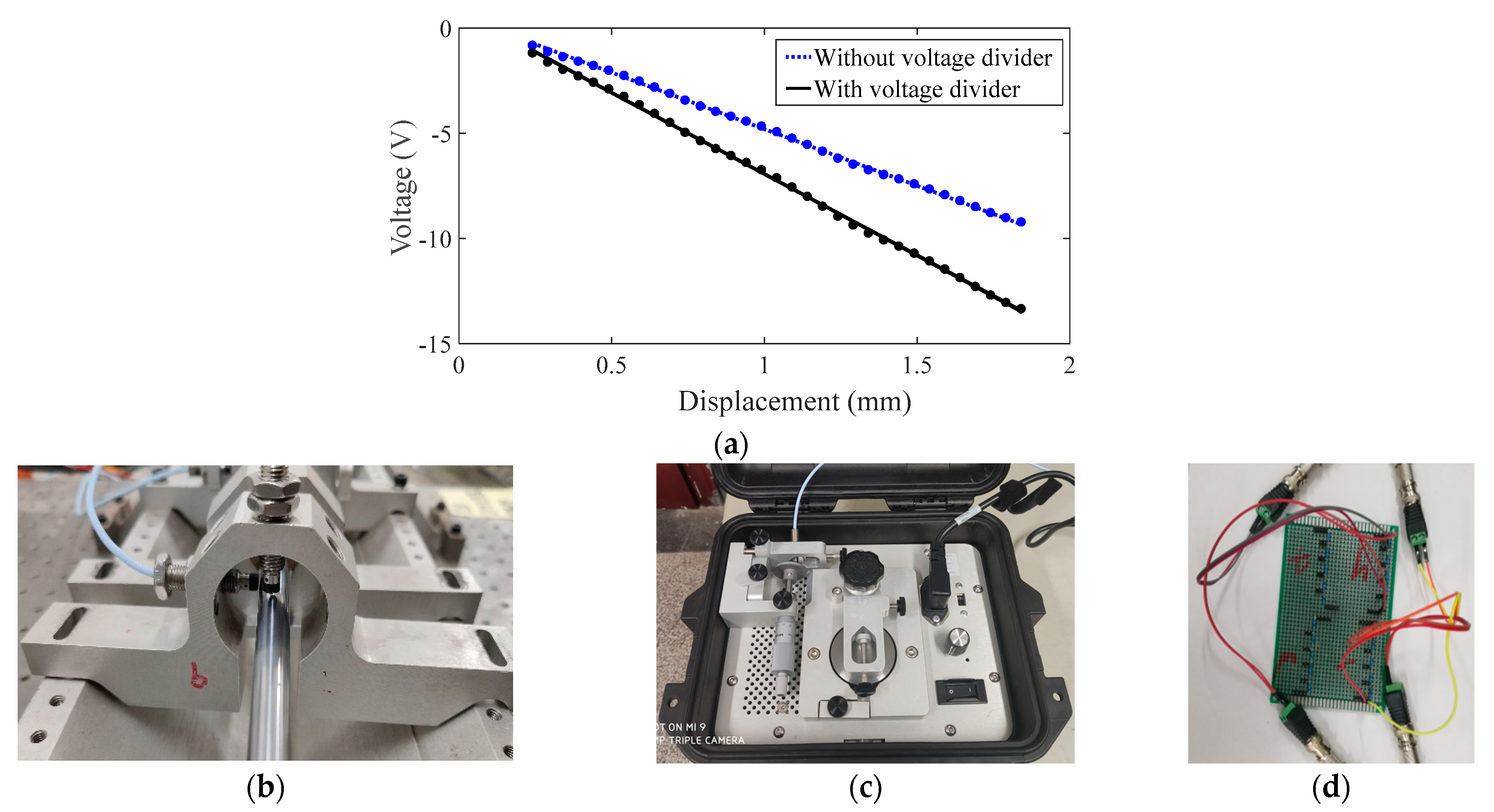
For the signal processing, the maximum output voltage of the transducers can reach 15 V for the large deflection of the flexible shaft with a diameter of 10 mm. This limit value exceeds the measurement range of plus or minus 10 V of the integrated signal acquisition device. Therefore, a new voltage divider composed of appropriate resistance units is designed for the enlargement of the measuring range of the signal processing system. Based on the data of the grouped transducers in
Figure 2b, the voltage divider in
Figure 2d is designed with the aid of a dedicated calibrator, as shown in
Figure 2c. By stepwise in-/decreasing of the gain of the voltage signal, the drop-down curve of voltage with respect to displacement is tracked, as shown in
Figure 2a. Through the comparison of the overall transducer sensitivity in
Figure 2a, the sensitivity of the eddy current displacement transducers with a voltage divider can be reduced from 7.87 V/mm to 5.38 V/mm. As such, a new voltage divider can be utilized to enhance the sensitivity and the dynamic range of various eddy current displacement transducers, by adjusting the values and arrangement of resistance units.
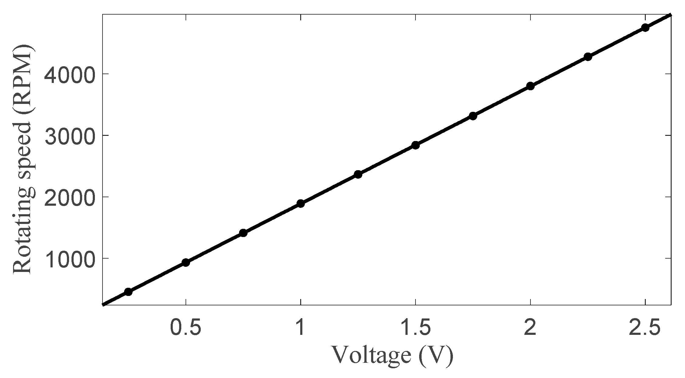
Considering the impedance in the speed control circuit, it is necessary to calibrate the sensitivity of the rotational speed control system to achieve accurate correction of the rotating speed. The proportional linear relationship between the input voltage and the rotating speed, as shown in
Figure 3, can be obtained through multiple sets of measurements, from which the ratio between the input voltage and the rotating speed is 1892 RPM/V.
After dynamic balancing emendation of the rotor system, the seal of the stator is fitted through flexible O-rings, which provide an elastic connection with the support. Therefore, the rotor-to-stator stiffness represents not only the separately equivalent stiffness of each section of the shaft but also a contribution of the elastic stiffness of the entire support system. Therefore, it is a very pivotal step to find the kinematic yet accurate parameters of the rotor/stator testing system, taking into account the rotor and stator attachments in the pedestal.
3. Theoretical Model of the Rotor/Stator Testing System
Based on the rotor/stator testing system depicted in
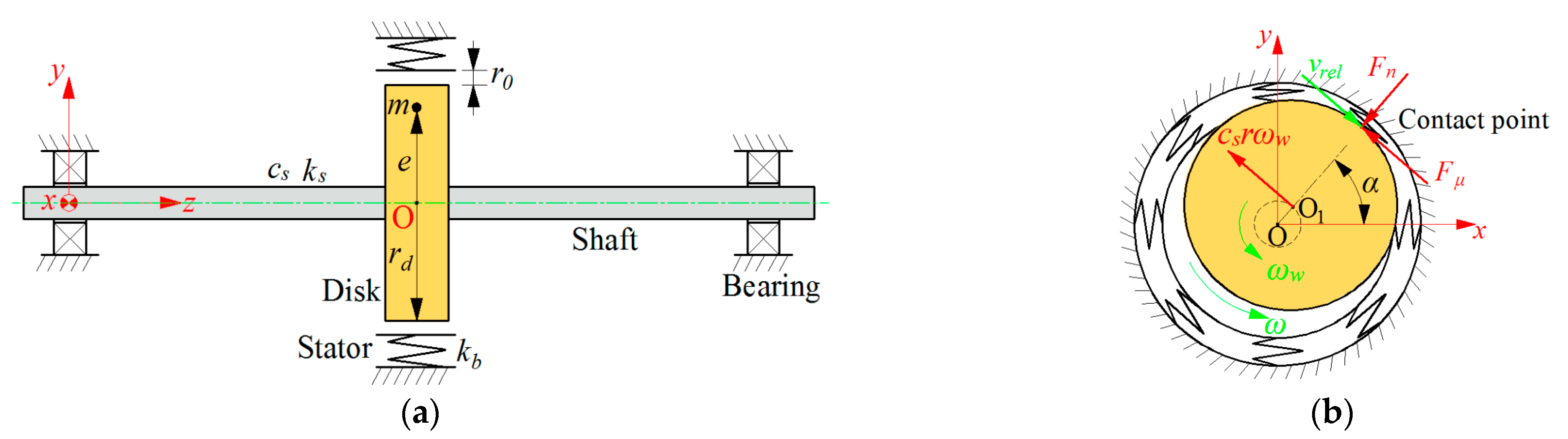
Figure 1, the coordinate system of the rotor/stator rubbing system with the origin O is defined, as visualized in
Figure 4, where a Jeffcott rotor is made up of a long and slender shaft fixed with a disk at the middle of the shaft, which is supported at the ends using two symmetric bearings. The stator is assumed to be rigidly fixed and is modeled as a symmetrical set of radial springs with isotropic stiffness
kb. Due to the unbalanced mass
m at the distance
e from the geometrical center O
1 of the disk, the radial displacement
of the rotor can exceed the clearance
r0 between the rotor and the stator, and rubbing with normal force
Fn and friction force
occurs. At the contact point, the whirl frequency of the rotor and the relative velocity between the rotor and the stator are respectively represented as
and
. The whirling angle between the radius displacement
r at the contact point and the horizontal direction is denoted by α.
Following [
5], taking into account the lubrication of the contact surfaces by appropriate and rational selection of the friction coefficient
μ without the gravity, the force relation for a rotor/stator rubbing system can be physically described as the Jeffcott rotor in contact with a non-rotating susceptible circumferential stator or a mechanical seal in the following differential equation:
where
cs denotes the damping parameter,
ks the stiffness of the rotor, and
the rotating angular speed of the rotor. Heaviside function
is one in the case of contact with
and zero otherwise. Sign function
represents the direction change of the friction force
Fμ and fluctuates between −1 and 1 in the case of
, i.e.,
. When the rotor whirls forward with
,
for
. On the contrary, when the rotor whirls backward with
and/or a large radial displacement
r, then
for
. Thus, no rub occurs with
, and rub occurs with
for forward whirl with
and backward whirl with
in the rotor/stator rubbing system governed by Equation (1).
Equation (1) can be recast into a set of first-order ordinary differential equations with discontinuous right-hand side.
where
,
,
,
,
, ,
,
, and I is a two-dimensional identity matrix
In particular, when
,
,
, or
, the tangent friction force
and the normal contact force
can be in the horizontal direction or vertical direction. This yields
By defining the non-dimensional variables as
,
,
,
,
,
,
,
,
,
, and
, Equation (1) can also be rewritten in the non-dimensional form
where the prime indicates the differentiation with respect to the dimensionless time variable
.
The system parameters of the rotor/stator rubbing system in Equations (1)–(4) are determined by the configuration parameters of the testing rotor and stator in
Table 1, whereas the kinetic parameters of the rotor/stator rubbing system, such as the equivalent stiffness
ks of the rotor and the dry friction coefficient
μ on the rubbing surface, cannot be directly obtained but must be characterized by the experimental parameters tracked from the dynamic load tests.
5. Experimental Results
According to the dimensionless parameters of the rotor/stator testing system in
Table 2, i.e.,
,
,
,
, and
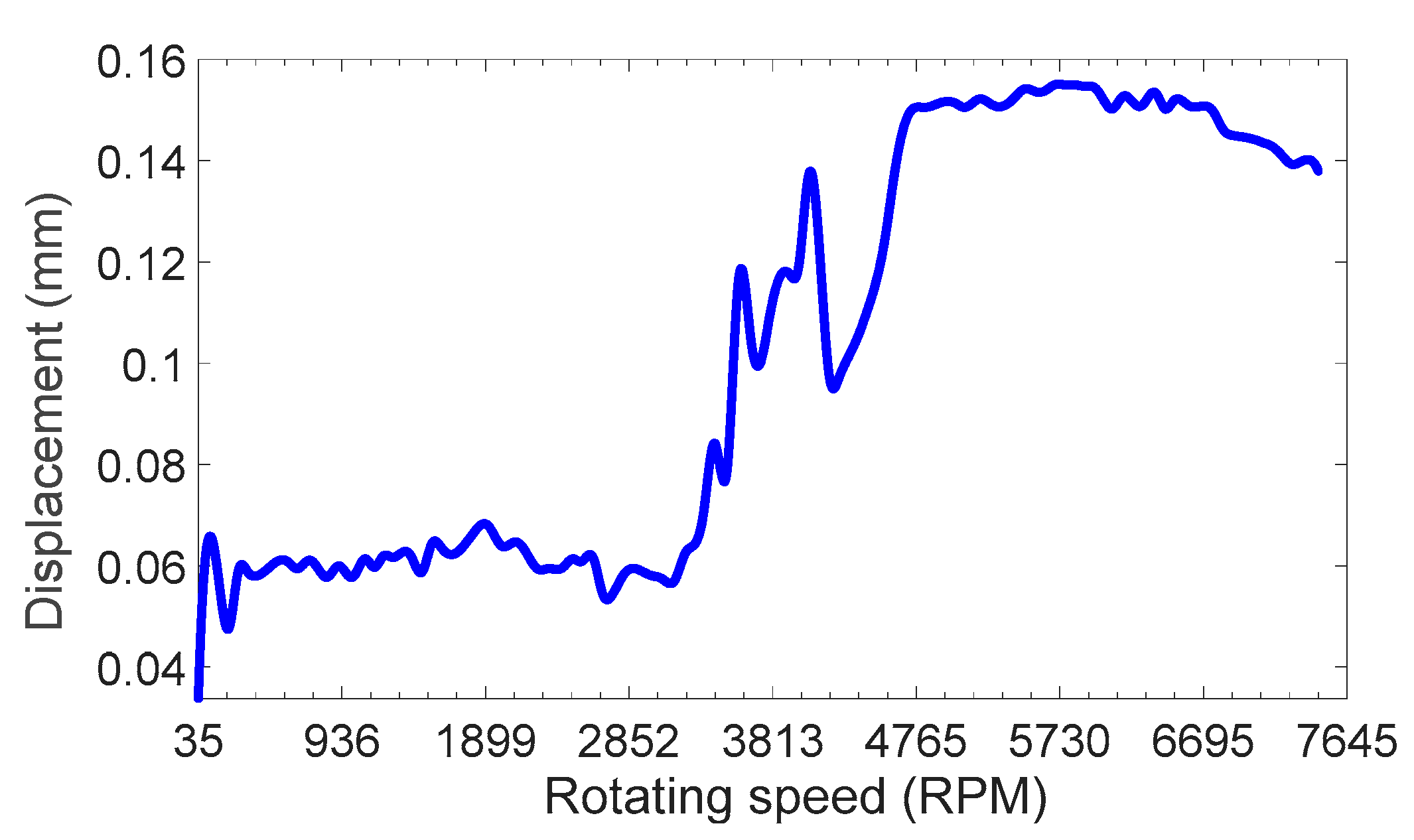
, the experimental tests are conducted to obtain the global dynamic characteristics of the rubbing responses. The experimental results of rotating speed-dependent variable displacement of the rotor are shown in
Figure 10. During the run-up process, the dual-peak curve of the rotor displacement is shown in
Figure 10a. It is shown that the first peak, labeled by P
1, is located at the natural frequency of the rotor system. Meanwhile, the second peak P
2 is located at the natural frequency of the coupled rotor/stator system. This phenomenon is not observed in a Jeffcott rotor system. It is indicated that an equivalent additional stiffness contributes to the rotor/stator rubbing system, resulting in the fluctuation of the system parameters. During the coast-down process, the rotor rapidly increases from 0 to 9494 RPM within 10 s and maintains this speed for 5 s before gradually decelerating to 82 RPM. It is seen from the rotor displacement in
Figure 10b that the ‘jump’ phenomenon appears with the displacement dramatically increasing from 2 mm to 4 mm. According to theoretical analysis [
5,
15] and experimental study [
23], partial rub ceases to exist with the occurrence of dry friction backward whirl at the ‘jump’ point during the coast-down process. It is also seen that the displacement of the rotor is much greater than the clearance when the rotating speed of the rotor slows to 5260 RPM. In addition, a negative super-synchronous frequency component can be derived in full spectrum. According to the response characteristics of dry friction backward whirl in [
5,
15,
17], it is concluded that dry friction backward whirl is induced when the rotating speed exceeds 5260 RPM. Then, as the rotating speed of the rotor gradually decreases to 82 RPM, the rotor cannot detach from the stator in dry friction backward whirl.
According to the response behavior of the rotor/stator rubbing system illustrated in [
5,
7,
23], the rotor orbit and full spectrum are employed to capture the performance of the whirling responses of the rotor/stator testing system. Then, by the aid of experimental data, the orbits and the full spectra of the representative rotor responses in the rotor/stator testing system are exemplified in
Figure 11. In the following figures, the rotor orbit is drawn with the displacement of the rotor represented by blue curves and the clearance between the rotor and stator represented by dotted red curves.
Figure 11a shows the rotor response of no rub motion of the rotor/stator testing system at
. It is seen from the orbit that the displacement
r of the rotor is less than the clearance
r0, i.e.,
r <
r0. It is also concluded from the full spectrum that a positive frequency component equal to the rotating speed of
is especially dominant, which is in agreement with current knowledge.
Figure 11b gives the rotor response of synchronous full annular rub of the rotor/stator testing system at
. It is seen from the orbit that the displacement
r of the rotor is greater than the clearance
r0, i.e.,
r >
r0. It is also concluded from the full spectrum that the dominant frequency component is also one equal to the rotating speed of
.
Figure 11c shows the rotor response of partial rub of the rotor/stator testing system at
. It is seen from the orbit that the displacement
r of the rotor is partly greater than the clearance
r0, i.e.,
r >
r0 and
r <
r0. It is also concluded from the full spectrum that a dominant negative frequency component appears for the backward whirl of the rotor opposite to its forward rotation. Therefore, the rotor response of partial rub with backward whirl is excited by both the backward and forward excitation mechanisms. All these characteristics from experimental data are in agreement with those from the theoretical solutions in [
15].
Figure 11d exhibits the rotor response of dry friction backward whirl of the rotor/stator testing system at
. It is seen from the orbit that the displacement of the rotor is much greater than the clearance
r0, i.e.,
, showing the large deformation of the rubbing rotor. It is indicated from the full spectrum that an observable negative super-synchronous frequency component far away from the negative natural frequency of the coupled nonlinear rotor/stator rubbing system is detected. With this condition, the direction of friction force can be inverted when the displacement of the rotor is sufficiently large to make the whirling speed exceed the circumferential speed of the rotor at contact points, i.e.,
in Equation (1). Therefore, dry friction backward whirl is a self-excited motion, during which the friction force on the contact surfaces can input or dissipate energy for the lateral vibration of the rotor.
Regardless of these differences between the mathematical model and the testing unit, the response types of the different whirling motions with different rotating speeds can be determined according to the basic response characteristics of the rotor orbits and full spectrum. Then, the experimental results of no rub motion, synchronous full annular rub, partial rub, and dry friction backward whirl are compared with the theoretical solutions. It is shown that the response characteristics of the experimental results compare very favorably with those of the theoretical solutions in [
5,
15,
17].
Based on the bifurcation and rubbing behaviors of the mathematical model of the rotor/stator rubbing system, the existence boundaries of the solutions for all phases of whirling motion have been rigorously determined in our previous work [
5]. The boundary of no rub motion is defined by the parameter equation with
. For the solutions in the phase with rubbing, bifurcation theory is utilized to determine the stability boundaries of synchronous full annular rub with constant amplitude at a frequency equal to the rotating speed of the rotor. The existence boundary of synchronous full annular rub is defined by the saddle-node bifurcation condition. The boundary between synchronous full annular rub and the quasi-periodic partial rub is defined by the Hopf bifurcation condition. As the rotating speed
increases, partial rub ceases to exist when dry friction backward whirl upon is triggered by imbalance. Taking into account the backward whirl frequency corresponding to the mode of the coupled nonlinear rotor/stator system, the critical condition for the onset of dry friction backward whirl or the loss of the stability of partial rub can be derived by the multiple scale method. Then, the boundaries of all phases of whirling motion can be determined by the critical solutions in the parameter plane of the rotating speed and friction coefficient, i.e.,
.
Compared to the theoretical boundaries of the steady rubbing responses in the parameter region of
, the experimental results of the global responses of the rotor/stator testing system are illustrated in
Figure 12. The diagram is plotted by the curves for theoretical bifurcation boundaries and the markers for experimental results. Following the theoretical solutions, curves
and
represent the critical rotating speed whereby rubbing occurs. Curve DF is the existence boundary of dry friction backward whirl. Curve DW is the boundary for the onset of dry friction backward whirl, which is triggered by imbalance and the cease of partial rub. In addition, the different coexistence regions are marked by numbers, that is, “0” denotes the coexistence region of no rub motion and dry friction backward whirl, and “1” the coexistence region of synchronous full annular rub, partial rub, and dry friction backward whirl.
In accordance with the theoretical solutions, the rotor responses obtained from experimental results are also illustrated by markers in
Figure 12. In the parameter plane of
, the cases respectively represented by the marker “(a)”, “(b)”, “(c)”, and “(d)” are introduced with one-to-one correspondence with the experimental results of no rub motion, synchronous full annular rub, partial rub, and dry friction backward whirl shown in
Figure 11, which agree well with theoretical solutions of the rotor/stator testing system.
For the case with
, which is represented by the magenta marker “(c)” in
Figure 12, the response of partial rub is illustrated in
Figure 11c. Under the given rotating speed, synchronous full annular rub can also occur with the different initial conditions, which is illustrated in
Figure 13a. Therefore, the coexistence region of “1” is validated by the experimental results of the coexistence of synchronous full annular rub and partial rub in the case of “(c)”. For the case with
, which is represented by the magenta marker “(d)” in
Figure 12, the response of dry friction backward whirl is illustrated in
Figure 11d. Under the given rotating speed, no rub motion can also occur with the different initial conditions, which is illustrated in
Figure 13b. Therefore, the coexistence region of “0” is validated by the experimental results of the coexistence of dry friction backward whirl and no rub motion in the case of “(d)”.
In summary, the scenario of the rotor/stator testing system with
is observed as no rub motion
synchronous full annular rub/partial rub
dry friction backward whirl/no rub motion, when the rotating speed of the rotor increases unrestrictedly from a very low value near zero to a value little larger than the natural frequency of the coupled nonlinear rotor/stator system. The global response characteristics of the rotor/stator testing system with
are well demonstrated and verified by the quantitative comparation between the experimental results and the theoretical solutions. On the other hand, the system parameters and their dimensionless values listed in
Table 1 and
Table 2 are also proved to be accurate by the identical global response characteristics of the rotor/stator testing system with
.
6. Dynamic Simulation Results
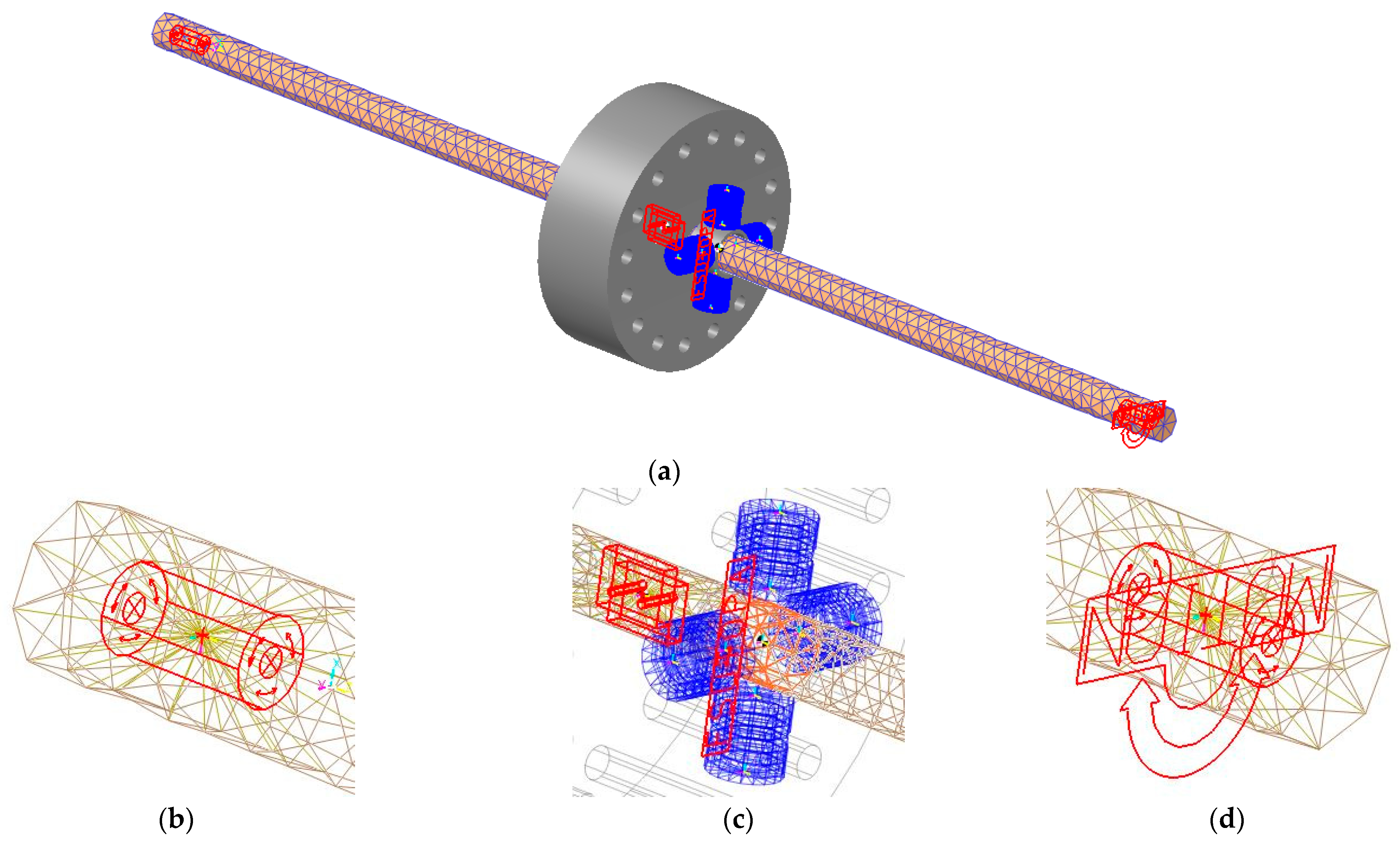
Based on the experimental parameters and the theoretical analysis of the rotor/stator testing system, the dynamic simulation of the rotor/stator rubbing is done by the flexible-multibody dynamic computing module of RecurDyn. The dynamic simulation model and the corresponding relations between the surface, edge, and position of the rotor/stator testing system are shown in
Figure 14. The rotor model is made up of a rigid disk and a flexible shaft with 1056 nodes and 3242 elements of three-dimensional Solid4, as shown in
Figure 14a. In addition, four virtual springs evenly distributed along the circumference are used to quantitatively simulate the elastic deformation of the stator during rubbing. In
Figure 14b–d, the rigid-flexible coupling constraints and connection relationships between the rigid disk, sliding bearings, and stator ring components are detailed. The stiffening zones and the rotating pairs are respectively represented by red rays and green symbols. In order to obtain the special coupling parameters between the stiffening zone and the flexible finite element of the shaft, such as the friction model, damping, and elasticity coefficient, an experimental modal analysis of the rotor testing system is carried out. Then, the parameters of the coupling rigid-flexible connection can be determined by comparing the modal parameters obtained from dynamic simulation and experimental modal analysis.
Following common practice, a low number of harmonics are carried out and successively increased until the resulting rubbing amplitude appears converged, i.e., does not change with increasing number of harmonics. The static deflection of the rotor is used as the initial condition of all the simulations. At least 500 time periods have been integrated in order to generate the correct results of the rotor/stator testing system. On the same parameter plane of
, as depicted in
Figure 12, the dynamic simulation results of the global response characteristics of the rotor/stator testing system with
,
,
, and
are also demonstrated by markers in
Figure 15. For the dynamic simulation results in the parameter plane of
, “green markers” represent regular dynamics in accord with theoretical solutions, and “red markers” represent abnormal whirling motion. It is obvious that the dynamic simulation results of the global responses are in good agreement with the theoretical solutions of the rotor/stator testing system with
μ ranging from 0 to 0.4 and
ranging from 0 to 1.3.
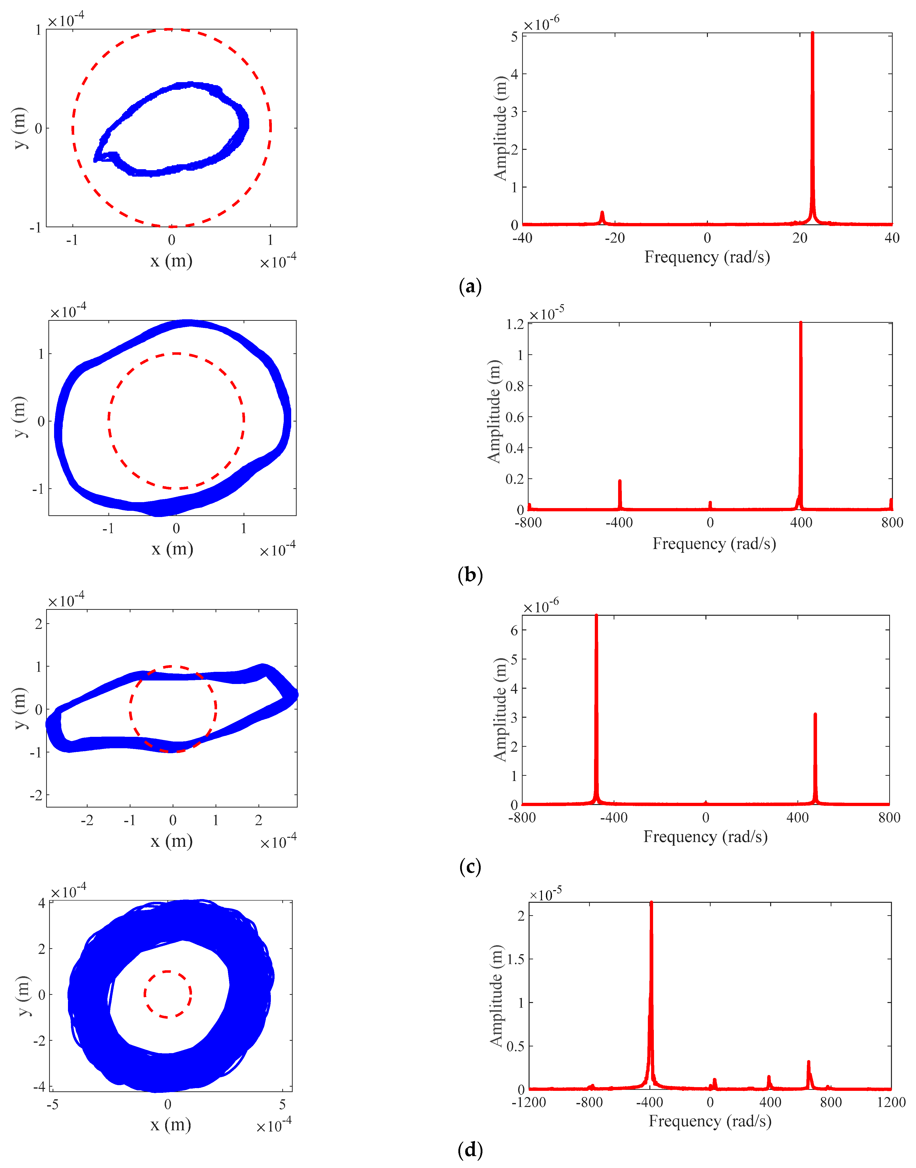
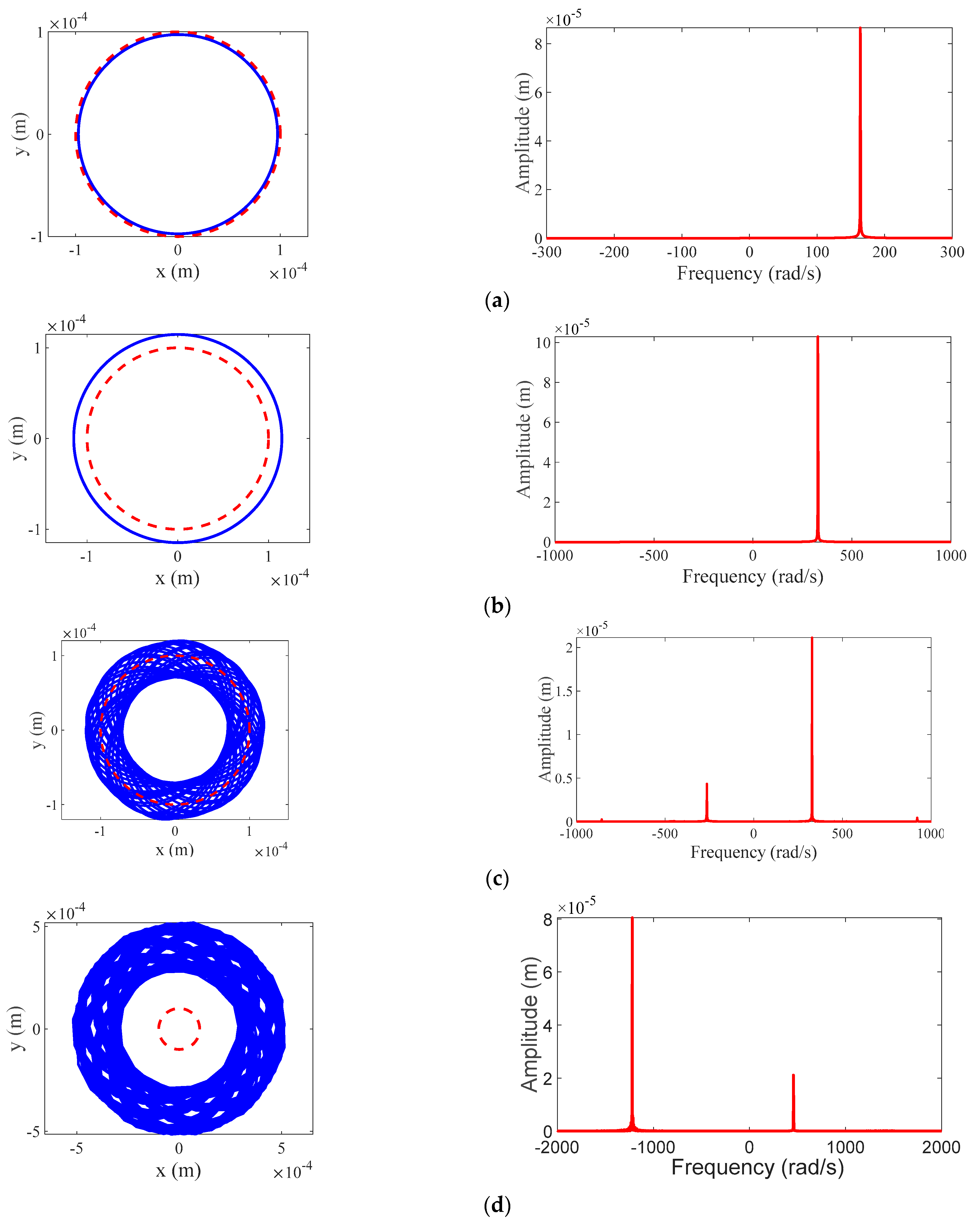
In order to make the global response characteristics of the rotor/stator testing system clearer, the dynamic simulation results of rotor orbit and full spectrum are confirmed in
Figure 16. The rotor responses of no rub motion, synchronous full annular rub, partial rub, and dry friction backward whirl, respectively—corresponding to the cases represented by the markers “(a)”, “(b)”, “(c)”, “(d)” and (e) on the parameter plane of
in
Figure 15—are shown in
Figure 16.
Figure 16a exhibits the rotor response of no rub motion with
and
.
Figure 16b exhibits the rotor response of synchronous full annular rub with
and
.
Figure 16c exhibits the rotor response of partial rub with
and
. It is seen from the full spectrum of the three types of responses that the positive frequency component equal to the rotating speed is especially dominant.
Figure 16d exhibits the rotor response of dry friction backward whirl with
and
, wherein the dominant frequency component is negative and opposite to the rotating speed. All of the rotor orbit and full spectrum results obtained from dynamic simulation agree well with what is derived by theoretical solutions of the rotor/stator testing system in Equation (1).
For the evaluation to the global response characteristics of the rotor/stator testing system, the orbits and full spectra of the rotor in the theoretical regions of different rubbing motions (i.e., no rub motion, synchronous full annular rub, partial rub, and dry friction backward whirl) are validated by the overlapping of the extensive dynamic simulation results, the experimental results, and the theoretical solutions. The agreements indicate the ability of the developed mathematical model and the theoretical method proposed in [
5] to deal with the global response characteristics of the rotor/stator rubbing system with the system parameters validated by the experimental results. As can be demonstrated from the theoretical solutions, which are obtained solely with Equation (1), as is usually done, the existence boundaries of no rub motion, synchronous full annular rub, partial rub, and dry friction backward whirl can be rigorously determined with very high accuracy. Based on this criterion, it is proved repeatedly that the scenario of the rotor/stator testing system is determined as no rub motion
synchronous full annular rub
partial rub
dry friction backward whirl/no rub motion. It is also interesting to note that dry friction backward whirl exists from a very low rotating speed with sufficient friction coefficient, which is identical to the experimental results of rotating speed-dependent variable displacement of the rotor during coast-down process, as shown in
Figure 10b.
7. Stick-Slip Oscillation of Dry Friction Backward Whirl
From the verified mathematical model of the rotor/stator testing system, the relative velocity
in the governing equation of Equation (1) can be elaborately expressed as
For dry friction backward whirl with
, the relative velocity
can be positive, negative, or zero for the piecewise smooth rotor/stator rubbing system. Thus, the discontinuous boundary of
is defined as the switching manifold. When the rotor performs pure rolling with
, the motion state at the contact points is referred to as sticking. Therefore, the relative motion between the rotation and the whirling of the rotor at the contact points might result in the switching motion between rolling and slipping, also known as stick-slip oscillation. The characteristics of stick-slip oscillations in dry friction backward whirl of rotor/stator rubbing systems are theoretically illustrated in [
18,
19,
20], but not verified by the experimental findings and the dynamic simulation results.
Based on the experimental results of dry friction backward whirl, as illustrated in
Figure 16d, the velocities
and
of the rotor in the X and Y directions can be roughly obtained by respectively differentiating the horizontal and vertical displacements
x and
y. Then, with the aid of the displacements
x and
y as well as their corresponding velocity
and
, the relative velocity
between the rotating speed and the whirling speed of the rotor can be derived from Equation (19). The time history of the relative velocity
is shown in
Figure 17. It is seen that the relative velocity
oscillates around zero, indicating the dominant pure rolling of the rotor on the contact surfaces of dry friction backward whirl. Yet, extraordinarily, the relative velocity
is much greater than zero during 11–14 s, implying the intermittent slipping of the rotor. From the experimental findings, the switching motion between rolling and slipping, i.e., stick-slip oscillation, corresponds to the decidedly nonsmooth behavior of sliding bifurcation in a rotor/stator rubbing system, which has been theoretically detailed in [
18,
19,
20].
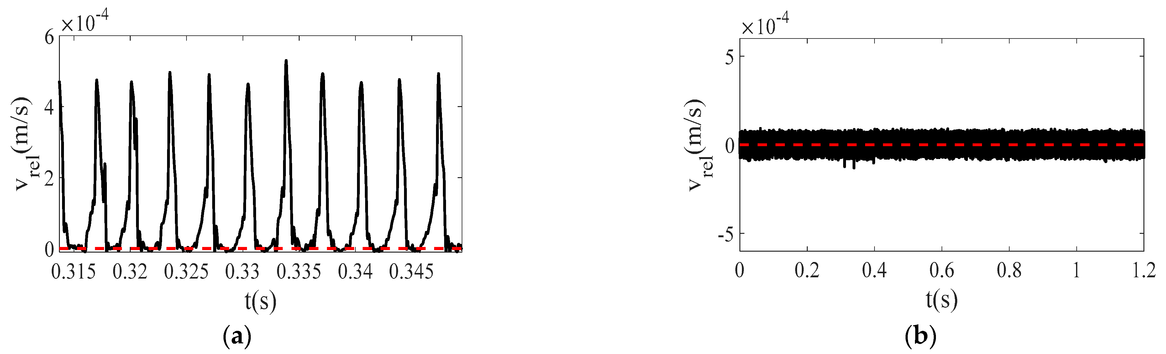
In a rotor/stator testing system with high speed, it is difficult to directly detect the quick switching between rolling and slipping in one period of stick-slip oscillation, but the characteristics of stick-slip oscillation can be captured by dynamic simulation. Based on the experimental parameters as described in
Table 1 and
Table 2 in the rotor/stator testing system, the relative velocity
can be obtained from the solutions of Equation (19) with the simulation results of
x,
y,
, and
. Then, using low-pass filtering, the simulation results of the time histories of the relative velocity
are given in
Figure 18. It is easily seen from
Figure 18a that the relative velocity
varies periodically up and down around the hypersurface of the switching manifold
. In the whole process of oscillation, the relative velocity
can either keep to zero, which corresponds to the pure rolling, or be greater than zero, which corresponds to the slipping of the rotor/stator testing system. Technically, the dynamic behavior of rolling-slipping oscillation in the rotor/stator testing system is defined as grazing-sliding bifurcation in [
19]. In
Figure 18b, the relative velocity
continuously oscillates around zero with small amplitude and can be seen to be almost equal to zero. The sticking motion corresponding to the pure rolling motion with
is easily identified for the rotor/stator testing system.
For both scenarios of rolling-slipping oscillation and pure rolling, the dynamic behavior of stick-slip oscillation is determined by dynamic simulation in the rotor/stator testing system. The characteristics of the relative velocity
in stick-slip oscillations are identical to the topological features of the nonsmooth trajectories around the switching manifolds theoretically derived from sliding bifurcation in [
18,
19,
20]. The oscillating behavior of the relative velocity
is also detected in the experimental measures.
8. Conclusions
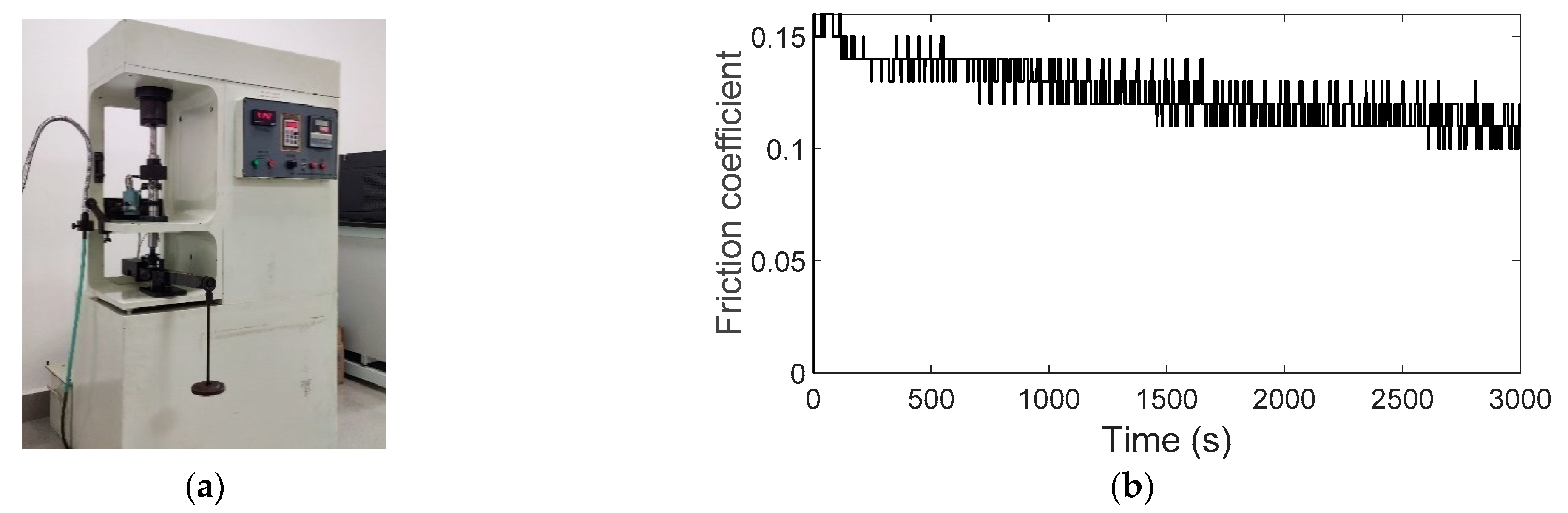
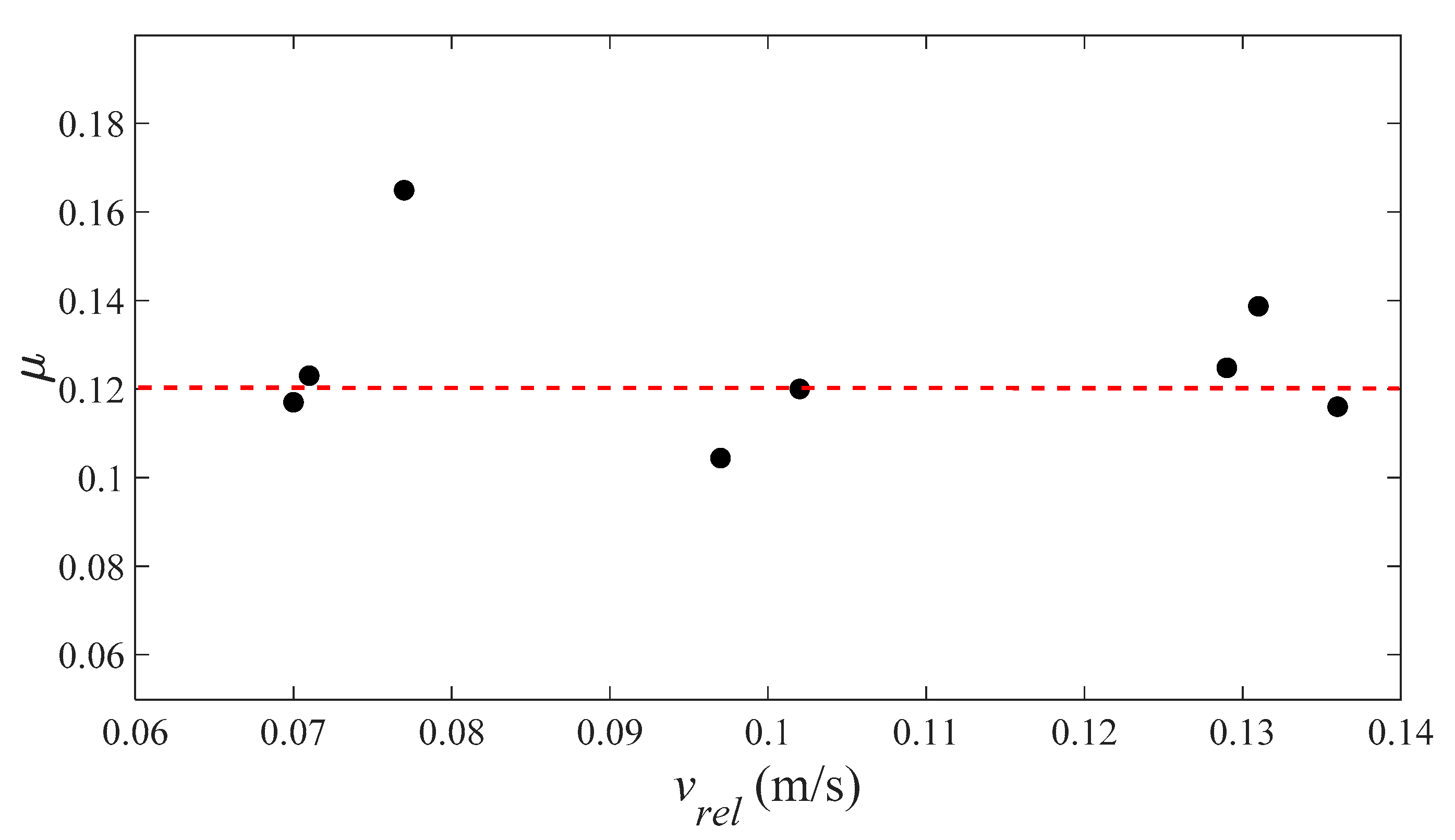
From the point of view of the global responses, the dynamic characteristics of the rotor/stator rubbing system are determined and evaluated by experiments and dynamic simulation. With the aid of a new voltage divider, the measuring range of the signal processing system grows with the sensitivity reducing from 7.87 V/mm to 5.38 V/mm. Taking into account the stiffness of the susceptible brass bushing bearings with rubber O-ring and the bearing/support stiffness, the equivalent stiffness of the rotor is accurately determined by the relationship between the natural frequency and the stiffness of the rotor. In addition, a new method for the determination of the kinetic dry friction between the rotor and the stator is proposed. Then, the friction coefficient between a brass stator and a steel rotor is determined as in the rotor/stator testing system.
Through experimental testing and dynamic simulation, the response characteristics of the rotor orbit and full spectrum, including all the four types of whirling motion (i.e., no rub motion, synchronous full annular run, partial rub, and dry friction backward whirl), are determined. According to the theoretical solutions in [
5], the results of experiments and dynamic simulation are in good accordance with those derived from theoretical solutions. During the run-up process, the characteristics of dual peak in the rotor displacement are detected. During the coast-down process, it is found that dry friction backward whirl can exist at a wide range of rotating speeds, that is, the interval from 9494 RPM to 82 RPM. On the parameter plane of rotating speed ranging from 0 to 1.3 and dry friction coefficient ranging from 0 to 0.4, all the boundary conditions of different whirling motions are proved valid by quantitative comparison. When
, synchronous full annular rub and partial rub can coexist. When
, dry friction backward whirl and no rub motion can coexist. In addition, the switching characteristics of the relative velocities in pure rolling and stick-slip oscillation are detected and validated by experiments and dynamic simulation. The final configuration for the experimental study and dynamic simulation on the global response characteristics can provide valuable insight into the dynamic characteristics of the rotor/stator rubbing system. It should be pointed out that the presented study does not address the gyroscopic effect and the torque of the rubbing rotor, which stands out as a potential focus for future work. For the purpose of making the research more useful and realistic under operational conditions, the gyroscopic effect and the torque on the transient nonlinear dynamic responses should also be accurately tested and calculated.


