
Inertia Support Capability Evaluation for Wind Turbine Generators Based on Symmetrical Operation


Abstract
1. Introduction
- (1)
- Considering the coupling effects among power, inertia, rotor speed, and aerodynamics, this paper analyzes the energy transfer process during the active inertia support of WTGs under virtual inertia control, identifying two key factors that influence the inertia support capability, which are real inertia and aerodynamic characteristics.
- (2)
- Furthermore, a symmetrical operation mode for WTGs is developed to assess the inertia support capability while accounting for prime mover characteristics, which is defined as an operation mode with a fixed ratio of WTGs’ rotor speed to SGs’ rotor speed.
- (3)
- Analysis results based on a standard IEEE 10-machine 39-bus system and an NREL 5MW WTG simulation model indicate that the inertia support provided by large WTGs has a minimal impact on their aerodynamic efficiency under non-fault conditions, allowing them to deliver inertia support equivalent to that of SGs with a power reduction of no more than 0.1%.
2. Mathematical Model and Virtual Inertia Control of WTGs
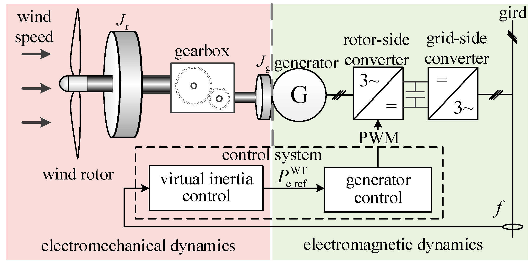
2.1. Mathematical Model of the WTG
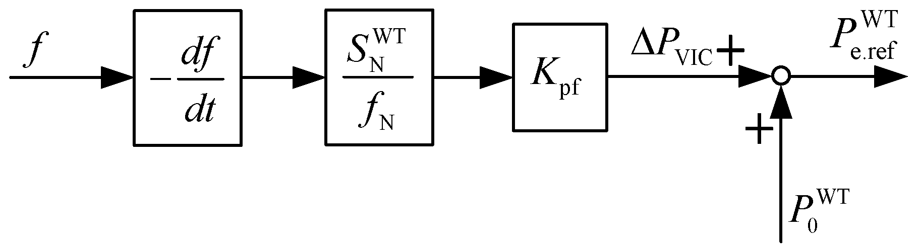
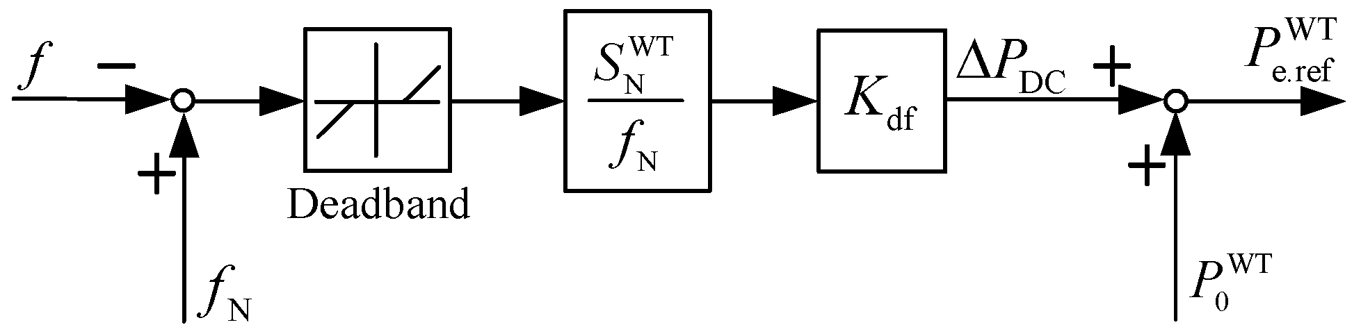
2.2. Virtual Inertia Control
3. Analysis of Influencing Factors for the Inertia Support Capacity of WTGs
3.1. Energy Transfer in Inertia Support Processes
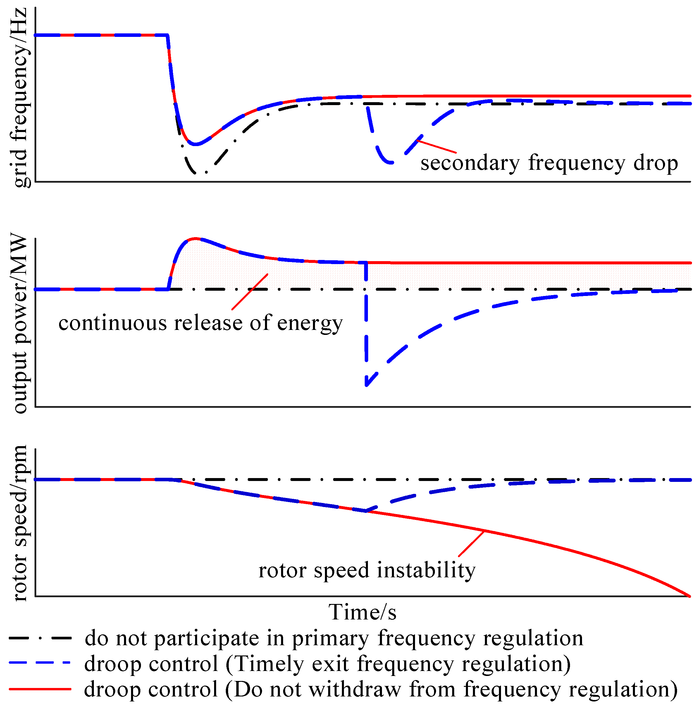
3.2. Difference in Energy Utilization Requirements Between Virtual Inertia Control and Primary Frequency Regulation
3.3. Factors That Influence Inertia Support Capacity
3.3.1. Real Inertia
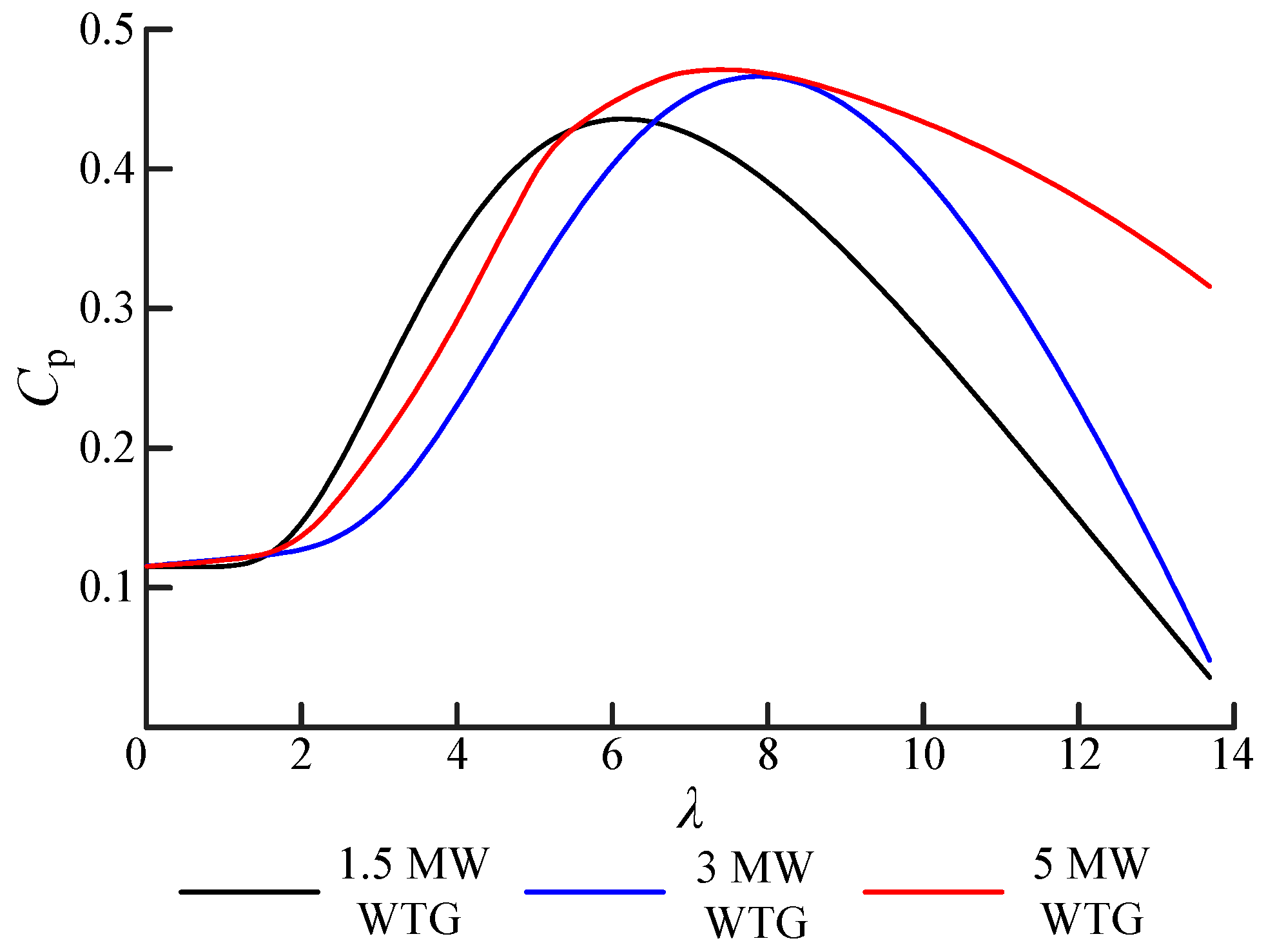
3.3.2. Aerodynamic Characteristics
4. Inertia Support Capability Evaluation for WTGs Based on Symmetrical Operation
4.1. Symmetrical Operation Mode of WTGs
4.2. Equivalent Inertia Calculation of WTGs Under Symmetrical Operation
4.3. Equivalent Inertia of WTGs Under Symmetrical Operation and Its Influence on Aerodynamic Efficiency
4.3.1. Equivalent Inertia Evaluation
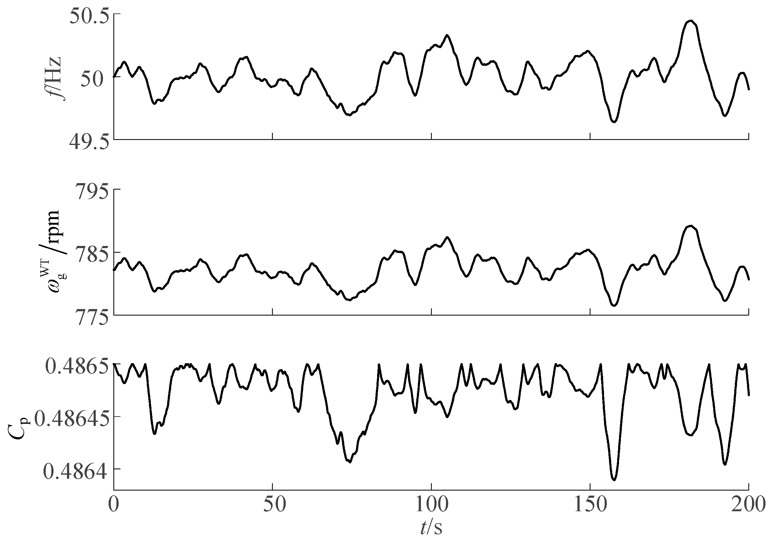
4.3.2. The Influence of Inertia Support on Aerodynamic Efficiency
4.4. The Influence of WTG Speed Variation Range on Equivalent Inertia and Aerodynamic Efficiency
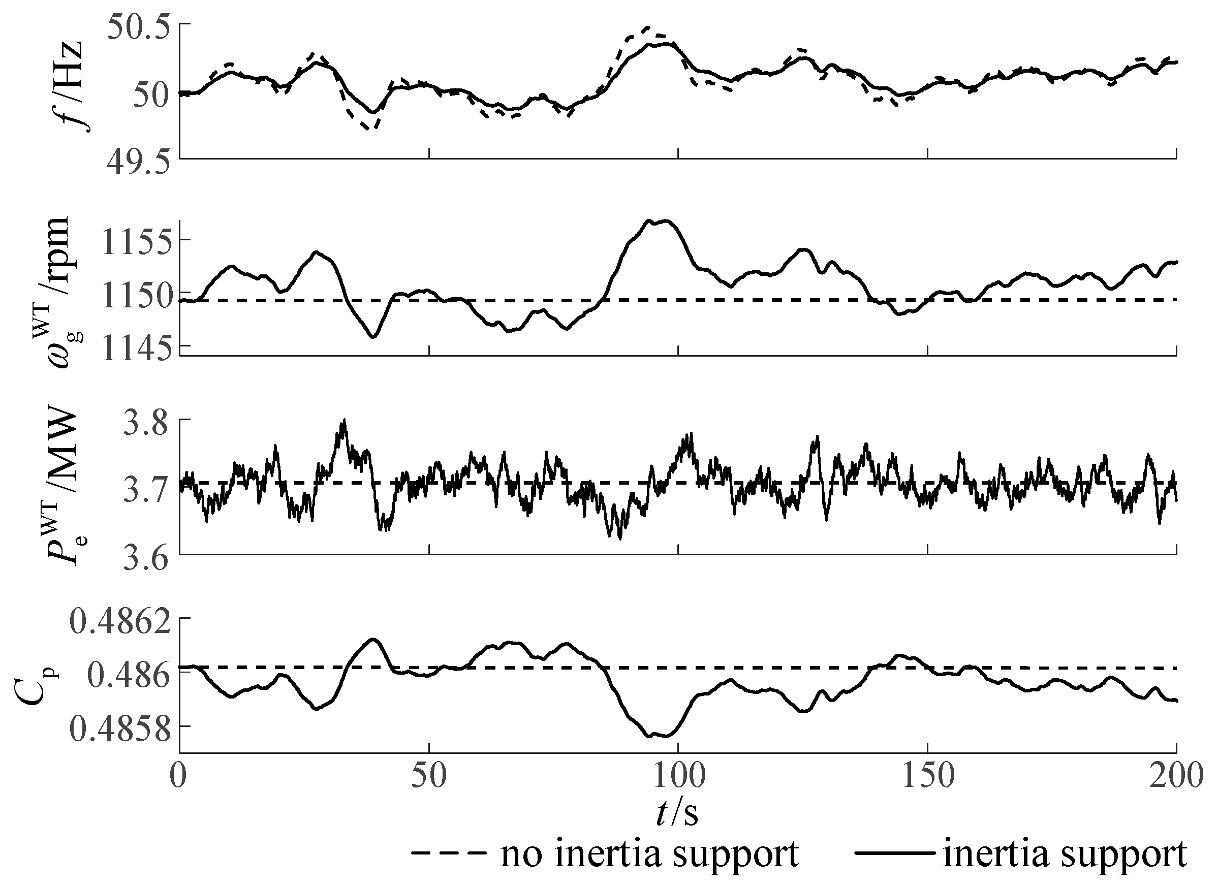
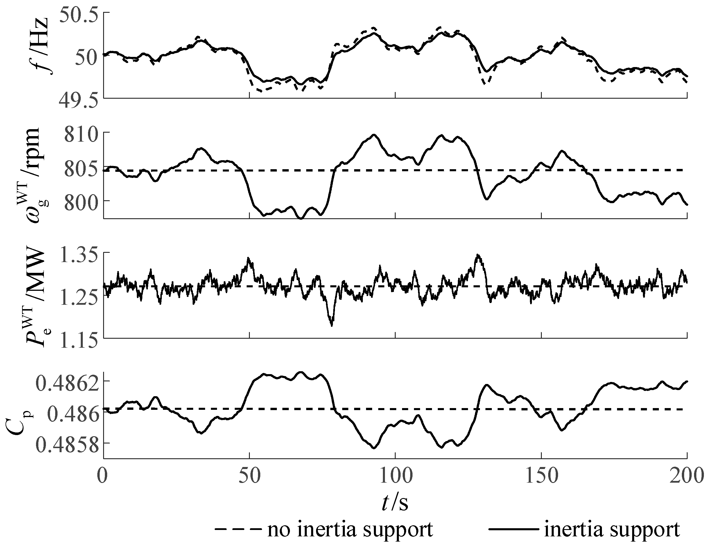
4.5. Verification of Virtual Inertia Control for WTGs Under De-Loading Operation
4.5.1. Case 1: Operating in the Same Rotor Speed Range
4.5.2. Case 2: Provide the Same Equivalent Inertia as G1
5. Conclusions
Author Contributions
Funding
Data Availability Statement
Conflicts of Interest
Appendix A
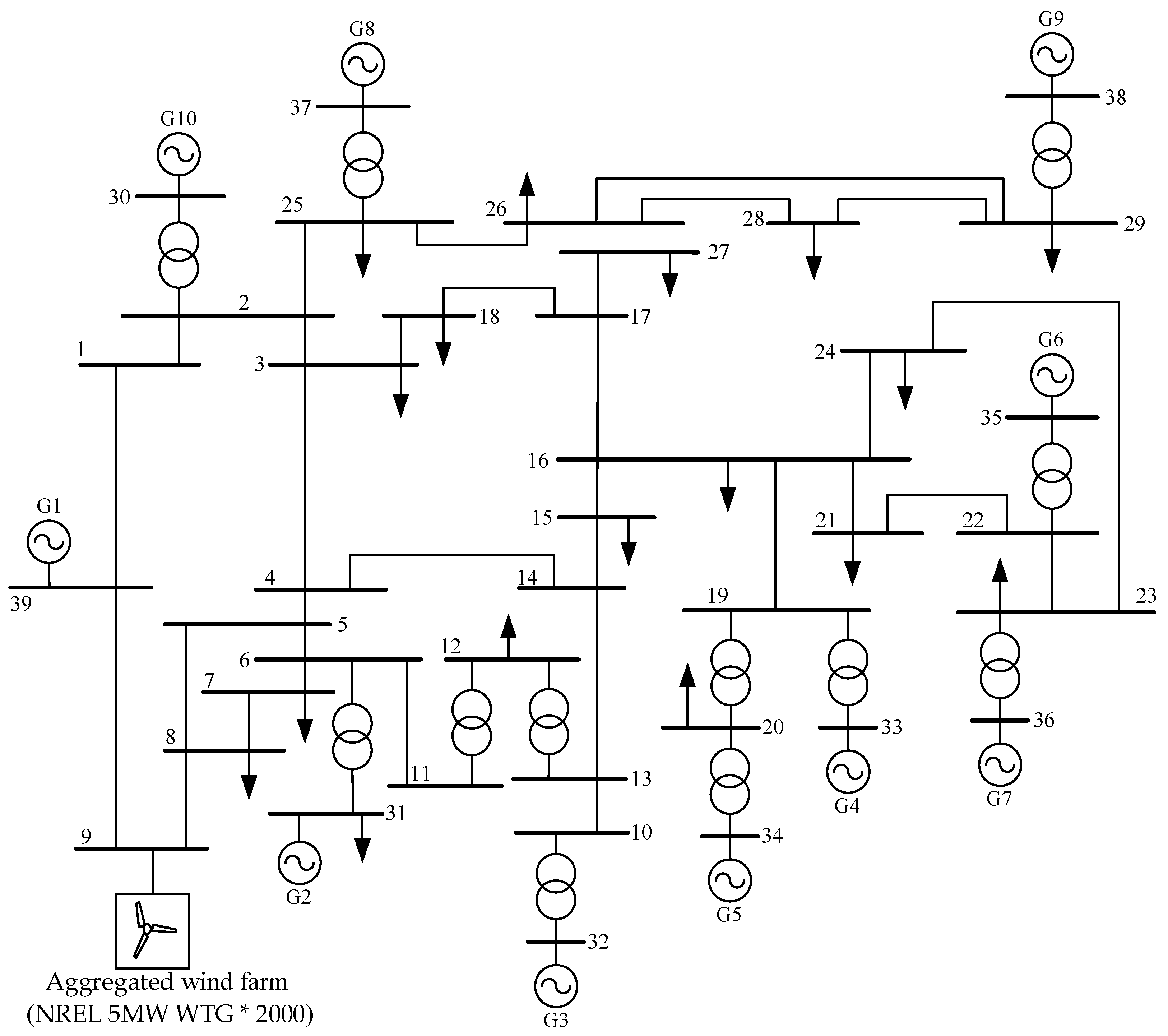
Appendix A.1. Parameters of Each SG in IEEE 10-Machine 39-Bus System

| SGs in the Standard IEEE 39-Bus System | Rated Capacity /MVA | Inertia Time Constant /s |
|---|---|---|
| G1 | 10,000 | 5 |
| G2 | 700 | 4.329 |
| G3 | 800 | 4.475 |
| G4 | 800 | 3.575 |
| G5 | 300 | 4.333 |
| G6 | 800 | 4.35 |
| G7 | 700 | 3.771 |
| G8 | 700 | 3.471 |
| G9 | 1000 | 3.45 |
| G10 | 1000 | 4.2 |
Appendix A.2. Parameters of 1.5 MW WTG and 5 MW WTG
| Parameter | Value of 1.5 MW WTG | Value of 5 MW WTG |
|---|---|---|
| wind rotor radius | 35 m | 63 m |
| wind rotor inertia | 2.96 × 10⁶ kgm2 | 3.54 × 10⁷ kgm2 |
| generator inertia | 53 kgm2 | 534.116 kgm2 |
| rated capacity | 1.5 MW | 5 MW |
| variable speed ratio | 87.965 | 97 |
| optimal tip speed ratio | 6.32 | 7.6 |
| maximum wind energy utilization coefficient | 0.4382 | 0.4865 |
Appendix B
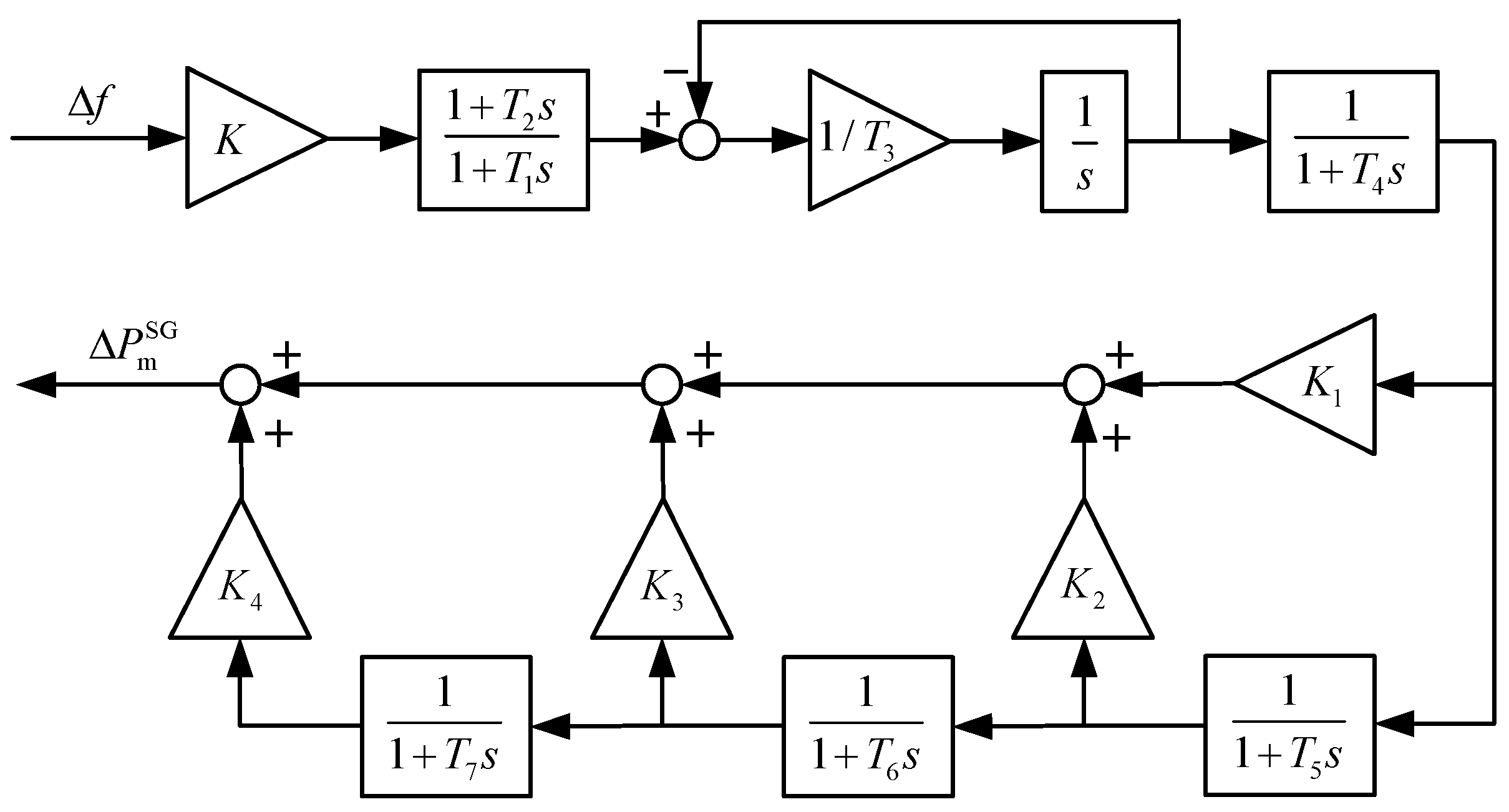
| Parameter | Value |
|---|---|
| controller gain | 5 |
| 0.2 | |
| 1 | |
| 0.6 | |
| 0.6 | |
| 0.5 | |
| 0.8 | |
| 1 | |
| 0.3 | |
| 0.25 | |
| 0.3 | |
| 0.15 |
References
- Shobug, M.A.; Chowdhury, N.A.; Hossain, M.A.; Sanjari, M.J.; Lu, J.; Yang, F. Virtual inertia control for power electronics-integrated power systems: Challenges and prospects. Energies 2024, 17, 2737. [Google Scholar] [CrossRef]
- Yap, K.Y.; Sarimuthu, C.R.; Lim, J.M.Y. Virtual inertia-based inverters for mitigating frequency instability in grid-connected renewable energy system: A review. Appl. Sci. 2019, 9, 5300. [Google Scholar] [CrossRef]
- Wang, H.; He, H.; Yang, Z.; Li, G.; Chen, Z.; Yang, J.; Zhang, G.; Dong, H. Frequency response methods for grid-connected wind power generations: A review. Electr. Power Syst. Res. 2023, 221, 109396. [Google Scholar] [CrossRef]
- Jafari, M.; Gharehpetian, G.B.; Anvari-Moghaddam, A. On the role of virtual inertia units in modern power systems: A review of control strategies, applications and recent developments. Int. J. Electr. Power Energy Syst. 2024, 159, 110067. [Google Scholar] [CrossRef]
- Fernández-Guillamón, A.; Gómez-Lázaro, E.; Muljadi, E.; Molina-Garcia, Á. A review of virtual inertia techniques for renewable energy-based generators. In Renewable Energy–Technologies and Applications; IntechOpen: Rijeka, Croatia, 2021. [Google Scholar]
- Hu, P.; Li, Y.; Yu, Y.; Blaabjerg, F. Inertia estimation of renewable-energy-dominated power system. Renew. Sustain. Energy Rev. 2023, 183, 113481. [Google Scholar] [CrossRef]
- Ekanayake, J.; Jenkins, N. Comparison of the response of doubly fed and fixed-speed induction generator wind turbines to changes in network frequency. IEEE Trans. Energy Convers. 2004, 19, 800–802. [Google Scholar] [CrossRef]
- Sun, D.; Liu, H.; Gao, S.; Wu, L.; Song, P.; Wang, X. Comparison of different virtual inertia control methods for inverter-based generators. J. Mod. Power Syst. Clean Energy 2020, 8, 768–777. [Google Scholar] [CrossRef]
- Tamrakar, U.; Shrestha, D.; Maharjan, M.; Bhattarai, B.P.; Hansen, T.M.; Tonkoski, R. Virtual inertia: Current trends and future directions. Appl. Sci. 2017, 7, 654. [Google Scholar] [CrossRef]
- Hosseini, S.A. Frequency control using electric vehicles with adaptive latency compensation and variable speed wind turbines using modified virtual inertia controller. Int. J. Electr. Power Energy Syst. 2024, 155, 109535. [Google Scholar] [CrossRef]
- Cheng, Y.; Azizipanah-Abarghooee, R.; Azizi, S.; Ding, L.; Terzija, V. Smart frequency control in low inertia energy systems based on frequency response techniques: A review. Appl. Energy 2020, 279, 115798. [Google Scholar] [CrossRef]
- Wang, X.; Li, K.; Liu, Y.; Cheng, H. Virtual inertia control of energy storage system in wind turbine based on extended state observer. Tran. China Electrotechnol. Soc. 2018, 33, 1257–1264. [Google Scholar]
- Bošnjaković, M.; Katinić, M.; Santa, R.; Marić, D. Wind turbine technology trends. Appl. Sci. 2022, 12, 8653. [Google Scholar] [CrossRef]
- Morren, J.; Pierik, J.; De Haan, S.W. Inertial response of variable speed wind turbines. Electr. Power Syst. Res. 2006, 76, 980–987. [Google Scholar] [CrossRef]
- Liu, B.; Zhao, J.; Huang, Q.; Milano, F.; Zhang, Y.; Hu, W. Nonlinear virtual inertia control of WTGs for enhancing primary frequency response and suppressing drivetrain torsional oscillations. IEEE Trans. Power Syst. 2021, 36, 4102–4113. [Google Scholar] [CrossRef]
- Harisha, K.; Jayasankar, V.N. Frequency stability of a wind-based energy system by virtual inertia controller of an inverter connected to grid. IETE J. Res. 2024, 70, 3134–3149. [Google Scholar] [CrossRef]
- Qiao, Y.; Guo, X.; Lu, Z.; Sun, R. Parameter setting of auxiliary frequency regulation of wind turbines considering secondary frequency drop. Power Syst. Technol. 2020, 44, 807–815. [Google Scholar]
- Jiang, C.; Cai, G.; Yang, D.; Liu, X.; Hao, S.; Li, B. Multi-objective configuration and evaluation of dynamic virtual inertia from DFIG based wind farm for frequency regulation. Int. J. Electr. Power Energy Syst. 2024, 158, 109956. [Google Scholar] [CrossRef]
- Tingyun, G.; Houyi, Z.; Bowen, L.; Junyi, M.; Qiang, F.; Yutao, X.; Qihui, F. Virtual inertia control to active support of the variable-speed wind turbine in variable frequency limit time. Front. Energy Res. 2024, 12, 1352385. [Google Scholar] [CrossRef]
- Lee, J.; Muljadi, E.; Srensen, P.; Kang, Y.C. Releasable kinetic energy-based inertial control of a DFIG wind power plant. IEEE Trans. Sustain. Energy 2016, 7, 279–288. [Google Scholar] [CrossRef]
- Qi, X.; Lei, L.; Yu, C.; Ma, Z.; Qu, T.; Du, M.; Gu, M. Adaptive distributed MPC based load frequency control with dynamic virtual inertia of offshore wind farms. IET Control. Theory Appl. 2024, 18, 2228–2238. [Google Scholar] [CrossRef]
- Khan, A.; Aragon, D.A.; Seyedmahmoudian, M.; Mekhilef, S.; Stojcevski, A. Inertia emulation control of PMSG-based wind turbines for enhanced grid stability in low inertia power systems. Int. J. Electr. Power Energy Syst. 2024, 156, 109740. [Google Scholar] [CrossRef]
- Mérida, J.; Aguilar, L.T.; Dávila, J. Analysis and synthesis of sliding mode control for large scale variable speed wind turbine for power optimization. Renew. Energy. 2014, 71, 715–728. [Google Scholar] [CrossRef]
- Wang, Y.; Meng, J.; Zhang, X.; Xu, L. Control of PMSG-based wind turbines for system inertial response and power oscillation damping. IEEE Trans. Sustain. Energy 2015, 6, 565–574. [Google Scholar] [CrossRef]
- Liu, H.; Li, M.; Liu, L.; Shi, J. Frequency trajectory planning-based transient frequency regulation strategy for wind turbine systems. IEEE J. Emerg. Sel. Top. Power Electron. 2021, 10, 3987–4000. [Google Scholar] [CrossRef]
- Zhang, X.; Chen, Y.; Yue, S.; Zha, X.; Zhang, D.; Xue, L. Retrospect and prospect of research on frequency regulation technology of power system by wind power. Power Syst. Technol. 2018, 42, 1793–1803. [Google Scholar]
- Jonkman, J. Definition of a 5-MW Reference wind Turbine for Offshore System Development; National Renewable Energy Laboratory: Golden, CO, USA, 2009. [Google Scholar]
- Ren, Y.; Li, L.; Brindley, J.; Jiang, L. Nonlinear PI control for variable pitch wind turbine. Control Eng. Pract. 2016, 50, 84–94. [Google Scholar] [CrossRef]
- Pai, M.A. Energy Function Analysis for Power System Stability; Kluwer Academic Publishers: Boston, MA, USA, 1989. [Google Scholar]
- Huang, C.; Li, F.; Jin, Z. Maximum power point tracking strategy for large-scale wind generation systems considering wind turbine dynamics. IEEE Trans. Ind. Electron. 2015, 62, 2530–2539. [Google Scholar] [CrossRef]
- Qin, X.; Su, L.; Chi, Y.; Guo, Q.; Xu, X. Functional orientation discrimination of inertia support and primary frequency regulation of virtual synchronous generator in large power grid. Autom. Electr. Power Syst. 2018, 42, 36–43. [Google Scholar]
- Boukhezzar, B.; Siguerdidjane, H.; Hand, M.M. Nonlinear control of variable-speed wind turbines for generator torque limiting and power optimization. J. Sol. Energy Eng. 2006, 128, 516–530. [Google Scholar] [CrossRef]
- GB/T 15945-2008; Power Quality—Frequency Deviation for Power System. Standardization Administration of China: Beijing, China, 2008.
- Abolvafaei, M.; Ganjefar, S. Maximum power extraction from a wind turbine using second-order fast terminal sliding mode control. Renew. Energy 2019, 139, 1437–1446. [Google Scholar] [CrossRef]
- Chen, Z.; Yin, M.; Zhou, L.; Xia, Y.; Liu, J.; Zou, Y. Variable parameter nonlinear control for maximum power point tracking considering mitigation of drive-train load. IEEE/CAA J. Autom. Sin. 2017, 4, 252–259. [Google Scholar] [CrossRef]
- Yao, S.; Chetan, M.; Griffith, D.T.; Escalera Mendoza, A.S.; Selig, M.S.; Martin, D.; Kianbakht, S.; Johnson, K.; Loth, E. Aero-structural design and optimization of 50 MW wind turbine with over 250-m blades. Wind Eng. 2022, 46, 273–295. [Google Scholar] [CrossRef]
- Guo, Y.; Bao, W.; Ding, L.; Liu, Z.; Kheshti, M.; Wu, Q.; Terzija, V. Analytically derived fixed termination time for stepwise inertial control of wind turbines—Part II: Application strategy. Int. J. Electr. Power Energy Syst. 2020, 121, 106106. [Google Scholar] [CrossRef]


| SGs in the Standard IEEE 39-Bus System | Real Inertia of Each SG/kgm2 | Real Inertia of the NREL 5 MW WTG Under the Same Capacity/kgm2 | Real Inertia of the NREL 1.5 MW WTG Under the Same Capacity/kgm2 |
|---|---|---|---|
| G1 | 7.04 × 10⁵ | 1.32 × 10⁶ | 1.05 × 10⁶ |
| G2 | 4.27 × 10⁴ | 9.22 × 10⁴ | 7.32 × 10⁴ |
| G3 | 5.04 × 10⁴ | 1.05 × 10⁵ | 8.36 × 10⁴ |
| G4 | 4.03 × 10⁴ | 1.05 × 10⁵ | 8.36 × 10⁴ |
| G5 | 3.66 × 10⁴ | 3.95 × 10⁴ | 3.14 × 10⁴ |
| G6 | 4.90 × 10⁴ | 1.05 × 10⁵ | 8.36 × 10⁴ |
| G7 | 3.72 × 10⁴ | 9.22 × 10⁴ | 7.32 × 10⁴ |
| G8 | 3.42 × 10⁴ | 9.22 × 10⁴ | 7.32 × 10⁴ |
| G9 | 4.86 × 10⁴ | 1.32 × 10⁵ | 1.05 × 10⁵ |
| G10 | 5.91 × 10⁴ | 1.32 × 10⁵ | 1.05 × 10⁵ |
| SGs in the Standard IEEE 39-Bus System | Real Inertia of Each SG/kgm2 | Real Inertia of the NREL 5 MW WTG Under the Same Capacity/kgm2 | Real Inertia of the NREL 1.5 MW WTG Under the Same Capacity/kgm2 |
|---|---|---|---|
| G1 | 7.04 × 10⁵ | 1.19 × 10⁶ | 7.42 × 10⁵ |
| G2 | 4.27 × 10⁴ | 8.36 × 10⁴ | 5.20 × 10⁴ |
| G3 | 5.04 × 10⁴ | 9.55 × 10⁴ | 5.94 × 10⁴ |
| G4 | 4.03 × 10⁴ | 9.55 × 10⁴ | 5.94 × 10⁴ |
| G5 | 3.66 × 10⁴ | 3.58 × 10⁴ | 2.23 × 10⁴ |
| G6 | 4.90 × 10⁴ | 9.55 × 10⁴ | 5.94 × 10⁴ |
| G7 | 3.72 × 10⁴ | 8.36 × 10⁴ | 5.20 × 10⁴ |
| G8 | 3.42 × 10⁴ | 8.36 × 10⁴ | 5.20 × 10⁴ |
| G9 | 4.86 × 10⁴ | 1.19 × 10⁵ | 7.42 × 10⁴ |
| G10 | 5.91 × 10⁴ | 1.19 × 10⁵ | 7.42 × 10⁴ |
| SGs in the Standard IEEE 39-Bus System | Real Inertia of Each SG/kgm2 | Real Inertia of the NREL 5 MW WTG Under the Same Capacity/kgm2 | Real Inertia of the NREL 1.5 MW WTG Under the Same Capacity/kgm2 |
|---|---|---|---|
| G1 | 7.04 × 10⁵ | 5.85 × 10⁵ | 3.64 × 10⁵ |
| G2 | 4.27 × 10⁴ | 4.09 × 10⁴ | 2.55 × 10⁴ |
| G3 | 5.04 × 10⁴ | 4.68 × 10⁴ | 2.91 × 10⁴ |
| G4 | 4.03 × 10⁴ | 4.68 × 10⁴ | 2.91 × 10⁴ |
| G5 | 3.66 × 10⁴ | 1.75 × 10⁴ | 1.09 × 10⁴ |
| G6 | 4.90 × 10⁴ | 4.68 × 10⁴ | 2.91 × 10⁴ |
| G7 | 3.72 × 10⁴ | 4.09 × 10⁴ | 2.55 × 10⁴ |
| G8 | 3.42 × 10⁴ | 4.09 × 10⁴ | 2.55 × 10⁴ |
| G9 | 4.86 × 10⁴ | 5.85 × 10⁴ | 3.64 × 10⁴ |
| G10 | 5.91 × 10⁴ | 5.85 × 10⁴ | 3.64 × 10⁴ |
Disclaimer/Publisher’s Note: The statements, opinions and data contained in all publications are solely those of the individual author(s) and contributor(s) and not of MDPI and/or the editor(s). MDPI and/or the editor(s) disclaim responsibility for any injury to people or property resulting from any ideas, methods, instructions or products referred to in the content. |
© 2024 by the authors. Licensee MDPI, Basel, Switzerland. This article is an open access article distributed under the terms and conditions of the Creative Commons Attribution (CC BY) license (https://creativecommons.org/licenses/by/4.0/).
Share and Cite
Chen, Z.; Li, Y.; Zhou, Q. Inertia Support Capability Evaluation for Wind Turbine Generators Based on Symmetrical Operation. Symmetry 2025, 17, 31. https://doi.org/10.3390/sym17010031
Chen Z, Li Y, Zhou Q. Inertia Support Capability Evaluation for Wind Turbine Generators Based on Symmetrical Operation. Symmetry. 2025; 17(1):31. https://doi.org/10.3390/sym17010031
Chicago/Turabian StyleChen, Zaiyu, Yang Li, and Qian Zhou. 2025. "Inertia Support Capability Evaluation for Wind Turbine Generators Based on Symmetrical Operation" Symmetry 17, no. 1: 31. https://doi.org/10.3390/sym17010031
APA StyleChen, Z., Li, Y., & Zhou, Q. (2025). Inertia Support Capability Evaluation for Wind Turbine Generators Based on Symmetrical Operation. Symmetry, 17(1), 31. https://doi.org/10.3390/sym17010031