Article

A Channel-Sensing-Based Multipath Multihop Cooperative Transmission Mechanism for UE Aggregation in Asymmetric IoE Scenarios

1
School of Information Science and Technology, Beijing University of Technology, Beijing 100124, China
2
AsiaInfo Technologies (China) Inc., Beijing 100094, China
3
State Key Laboratory of Digital Manufacturing Equipment and Technology, School of Mechanical Science and Engineering, Huazhong University of Science and Technology, Wuhan 430074, China
*
Authors to whom correspondence should be addressed.
These authors contributed equally to this work.
Symmetry 2024, 16(9), 1225; https://doi.org/10.3390/sym16091225
Submission received: 28 August 2024 / Revised: 15 September 2024 / Accepted: 15 September 2024 / Published: 18 September 2024
(This article belongs to the Section Computer)

Abstract

:
With the continuous progress and development of technology, the Internet of Everything (IoE) is gradually becoming a research hotspot. More companies and research institutes are focusing on the connectivity and transmission between multiple devices in asymmetric networks, such as V2X, Industrial Internet of Things (IIoT), environmental monitoring, disaster management, agriculture, and so on. The number of devices and business volume of these applications have rapidly increased in recent years, which will lead to a large load of terminals and affect the transmission efficiency of IoE data transmission. To deal with this issue, it has been proposed to perform data transmission via multipath cooperative transmission with multihop transmission. This approach aims to improve transmission latency, energy consumption, reliability, and throughput. This paper designs a channel-sensing-based cooperative transmission mechanism (CSCTM) with hybrid automatic repeat request (HARQ) for user equipment (UE) aggregation mechanism in future asymmetric IoE scenarios, which ensures that IoE devices data can be transmitted quickly and reliably, and supports real-time data processing and analysis. The main contents of this proposed method include strategies of cooperative transmission and redundancy version (RV) determination, a joint combination of decoding process at the receiving side, and a design of transmission priority through ascending offset sort (AOS) algorithm based on channel sensing. In addition, multihop technology is designed for the multipath cooperative transmission strategy, which enables cooperative nodes (CN) to help UE to transmit data. As a result, it can be obtained that CSCTM provides significant advancements in latency and energy consumption for the whole system. It demonstrates improvements in enhanced coverage, improved reliability, and minimized latency.

1. Introduction

With the continuous progress of wireless communication technology, the Internet of Everything (IoE) applications are constantly changing [1,2]. As we look towards the future, the emergence of sixth-generation (6G) wireless communication stands at the forefront, promising unprecedented capabilities and transformative potential [3]. Building upon the foundation laid by its predecessors, 6G aims to revolutionize connectivity by delivering unparalleled speed, reliability, and versatility. Moreover, the 6G system includes many asymmetric IoE networks, including but not limited to dedicated satellite missions, unmanned aerial vehicles (UAV), smart cities, smart factories, and so on [4].
With projected peak data rates reaching terabits per second (Tbps level), latency reduces to mere microseconds ( 1  ms), the reliability is expected to increase from 99.999% in 5G to 99.99999% in 6G, and the coverage area expects to expand from 5% of the ocean surface and 20% of the land area in 5G to almost complete coverage encompassing the space–air–ground–sea in 6G [5]. The coverage requirements and energy consumption can be improved through the work in this paper, achieving a dual enhancement of coverage and reliability, especially in IoE applications. In addition, the criteria of connection density expand from 10 6 devices/ km 2 to 10 8 devices/ km 2 , and the network energy efficiency increases from 10 7 bits/J to 10 9 bits/J [5]. Moreover, 6G will unlock a new era of ultra-fast, low-latency communication that will power the next generation of applications and services. Moreover, user equipment (UE) aggregation mechanism and multipath cooperative transmission with multihop technology have enabled the above indicators to be achieved to some extent, and network conflicts and latency can be reduced through data diversion [6]. This kind of multipath cooperative transmission can be applied in various technologies recently, such as machine learning, millimeter wave, terahertz communication, edge computing, cloud computing, blockchain, and so on [7,8,9]. In addition, the UE aggregation mechanism and multipath cooperative transmission solutions provide other possibilities for continuous performance enhancement in real-time data processing [10].

1.1. Related Works

In wireless communication systems, the UE aggregation mechanism and multipath cooperative transmission have emerged as crucial techniques to enhance coverage area, reliability, and efficiency. Multipath cooperative transmission exploits the existence of multiple propagation paths between the transmitter and receiver to improve signal robustness against fading and interference through multipath transmission control protocol (MPTCP) [11]. At the same time, the UE aggregation mechanism increases data rates and system capacity with the assistance of multiple cooperative nodes (CNs) [12]. Moreover, the UE aggregation mechanism and multipath cooperative transmission represent emerging transmission technologies in wireless communications. These technologies constitute a promising software-defined architecture that can be realized with reduced cost, size, weight, and power (C-SWaP) compared to other transmission technologies [13,14,15]. However, due to the introduction of additional devices in the transmission process, an inevitable increase in energy consumption of the overall system will occur. Thus, the current focus of research is on how to comprehensively optimize factors, such as reliability, latency, coverage, and energy consumption costs.
Several research works have investigated the benefits and challenges of UE aggregation mechanism and multipath cooperative transmission in wireless communication systems. These studies have addressed various aspects, such as performance optimization [16], resource allocation [17,18], and interference management [19]. Additionally, emerging technologies, such as massive multiple-input multiple-output (MIMO) [2,20], mmWave communication [21], and network slicing [22] have been explored to further enhance the capabilities of UE aggregation mechanism and multipath cooperative transmission in future IoE of asymmetric wireless networks.
Hybrid automatic repeat request (HARQ) is a sophisticated error correction technique that is widely used in modern wireless communication systems to improve reliability and efficiency in data transmission. HARQ combines the benefits of both automatic repeat request (ARQ) and forward error correction (FEC) mechanisms, offering robustness against channel impairments, while minimizing retransmissions and maximizing spectral efficiency [23]. HARQ operates by transmitting data packets along with redundancy information, allowing the receiver to detect and correct errors in the received packets. In the event of a decoding failure, the receiver sends a feedback signal to the transmitter indicating which packets were successfully received and which require retransmission. HARQ employs various strategies to optimize these decisions, including incremental redundancy and chase combining. These methods leverage the redundancy in previously received packets to enhance error correction capabilities [24].
According to the description above, HARQ can be divided into two types, which are chase combining HARQ (CC-HARQ) and incremental redundancy HARQ (IR-HARQ). In CC-HARQ, the data transmitted in each transmission remain the same, but data packets are combined using the signal-to-interference-plus-noise ratio (SINR) as weights during decoding, allowing for time diversity gain [25,26]. In IR-HARQ, the content of each transmitted information packet is intentionally varied through special design. As a result, each retransmission provides additional coding gain, enhancing the comprehensiveness of decoding information and facilitating accurate decoding [23,27,28]. Moreover, when the channel conditions are favorable, the performances of both decoding methods are similar. However, the multi-version approach of IR-HARQ performs better in harsh channel conditions. Nonetheless, CC-HARQ offers the advantages of simpler signaling and lower system overhead [29,30,31].
In cellular networks, sidelink communication is standardized by the Third Generation Partnership Project (3GPP), known as proximity services (ProSe) in long-term evolution (LTE) [32] and as the sidelink in 5G New Radio (5G NR) [33]. Sidelink communication leverages the proximity of devices to establish direct communication links, offering several advantages such as low latency, improved reliability, and reduced network congestion. This mode of communication is particularly beneficial in scenarios where devices are in close proximity or when network infrastructure is limited or unavailable, such as in disaster recovery, public safety, and Industrial Internet of Things (IIoT) [34,35,36,37].

1.2. Main Contributions

This paper proposes a channel-sensing-based cooperative transmission mechanism (CSCTM) with hybrid automatic repeat request techniques for UE aggregation in future asymmetric IoE scenarios. In this mechanism, CNs prioritize neighboring UE using the auxiliary sorting algorithm, AOS, which is based on channel sensing. They also share information with surrounding CNs through sidelink technology to determine the transmission redundancy version (RV). This approach ensures optimal transmission efficiency across the entire system. As a result, CSCTM with AOS optimizes the coverage and transmission reliability of devices and reduces transmission latency and energy consumption costs to some extent. When based on this model, the main contributions of this study can be summarized as follows:
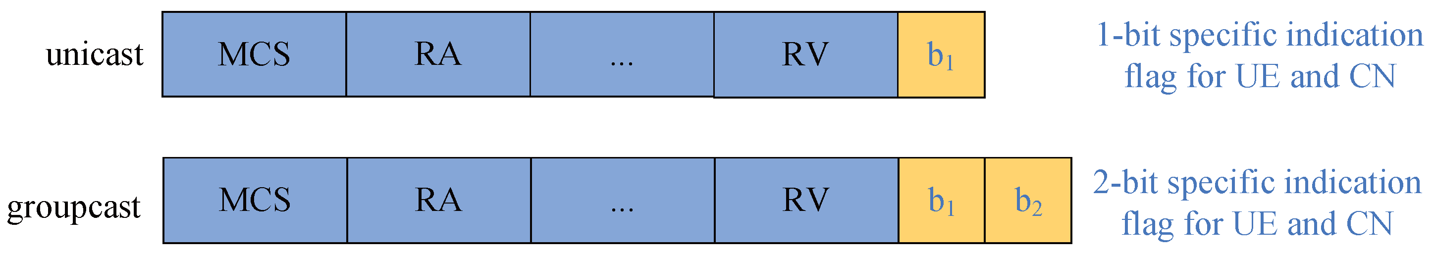
  • A new control signaling field is introduced to inform the cooperative transmission strategy of UE and CN through a unicast or groupcast method. The proposed control signaling can reduce the resource consumption of the next-generation node base station (gNB) sending information and better control the status of UE and CN.
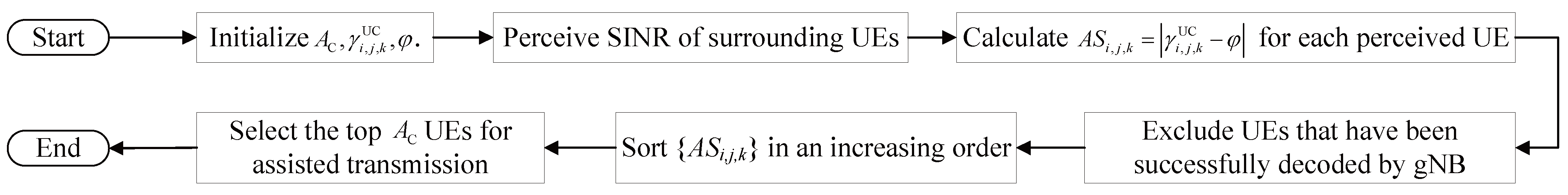
  • The AOS algorithm is designed to minimize resource consumption through prioritizing neighboring UE of each CN in the cooperative transmission stage. This can optimize the resource consumption of CN to solve the problem of capacity constraints.
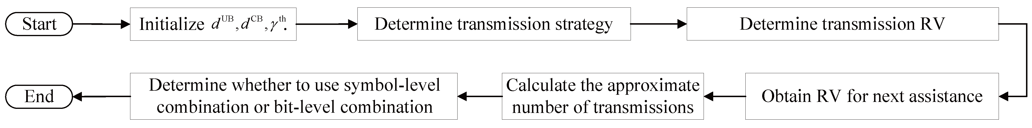
  • A novel mechanism CSCTM with HARQ for future asymmetric IoE scenarios is proposed in this paper, which determines transmission strategy by channel sensing and allocates optimal RVs for different transmitters. In addition, the CSCTM modifies the signal combination mechanism at the receiving end by employing various combining techniques for data retransmission from different transmitters.

1.3. Organization

The remainder of this article is organized as follows. Section 2 presents the system model, the design of the cooperative transmission procedure between UE, CN, and gNB, and the problem formulation. The theoretical calculation of transmission latency, the detailed design of the AOS algorithm, and the derivations of the average transmission number within CSCTM are described in Section 3. Section 4 evaluates the performances of the multipath cooperative transmission with HARQ and the proposed mechanisms under various environments and is followed by the conclusions in Section 5. In addition, the notation and operation descriptions of this paper are declared in Table 1.

2. System Model and Problem Formulation
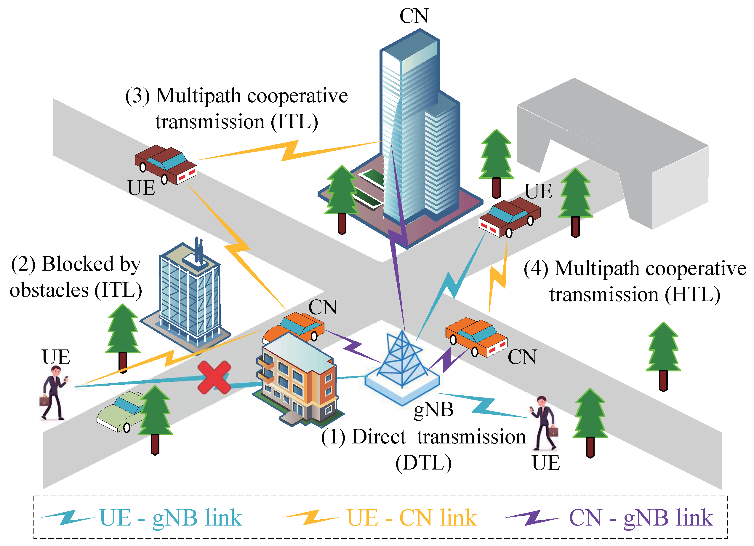
This section mainly discusses the system model, the design of the cooperative transmission procedure between UE, CN, and gNB, and the problem formulation.

2.1. System Model

This paper considers multipath cooperative transmission scenarios, as illustrated in Figure 1, wherein a heterogeneous network is assumed. All UE in the user equipment set U = 1 , , N U are randomly distributed inside the cell, and all CNs in the cooperation nodes set C = 1 , , N C are evenly distributed in the cell. Moreover, it is assumed that the maximal transmission power P t is fixed for every UE and every CN. The packet size of each task is identical. In addition, the SINR between any two devices can be donated by the following:
γ = P t P L Ω g 2 I + σ 2 ,
where g represents the fast channel fading and follows a Nakagami distribution [38] and g 2 is distributed according to a gamma distribution. Ω represents the shadowing effect and is modeled by a log-normal distribution. In addition, P L is the path loss of the channel, P t is the signal transmission power, I is the interference within devices, and the noise of the system is modeled as the Gaussian random noise with zero mean and variance σ 2 .
In this paper, the multihop technology utilizes a two-hop approach, wherein the UE transmits data to the gNB via the CN. Although data transmission between CNs can expand coverage, it also increases latency and energy consumption of one time segment. Additionally, the obstacles between the transmitter and receiver and out of the transmitter coverage will lead to low channel quality. Then assistance from other devices or changing the transmission strategy may be required in such scenarios.
The transmission scenario can be considered in different cases for different situations. In this paper, three different transmission links are discussed, namely, the direct transmission link (DTL), indirect transmission link (ITL), and hybrid transmission link (HTL). The decision regarding these transmission links is determined by the link quality between the UE, CN, and gNB. The factors that may affect channel quality include obstacles such as a long transmission distance, etc. Obstacles in wireless transmission refer to physical structures, objects, or environmental factors that obstruct the path between the transmitter and the receiver. These obstacles may include buildings, walls, trees, hills, and even atmospheric conditions, which will cause signal loss and interference. All of them can affect the distance of wireless data that can be reliably transmitted. In addition, the long distance between UE and the gNB results in significant path loss, leading to decreased SINR and reliability in data transmission. This can be mitigated by two or more CNs to assist with data transmission through the multipath. Here, we mainly talk about the most common situations as shown in Figure 1.
  • Direct transmission link (DTL): UE transmits data to gNB directly without any assistance. In this case, the channel quality between UE and gNB is good enough to support direct transmission, and UE is located in the coverage range of gNB, resulting in high communication quality characterized by a high SINR between them.
  • Indirect transmission link (ITL): UE transmits data to the nearby CN at first, then CN assists UE in transmitting data to gNB after decoding UE information successfully. Moreover, UE will terminate the transmission of information after CN confirms the assistance in transmitting the information. In this situation, the channel quality between UE and gNB is not good enough, which can occur in many scenarios, such as the presence of obstacles or long distances.
  • Hybrid transmission link (HTL): The data from UE can be decoded at CN and gNB simultaneously. In general, CN will decode the UE data successfully before gNB, then UE and CN transmit data to gNB jointly. In other words, UE continues transmitting data after CN decoding successfully. At this time, the channel quality between UE and gNB is similar to the channel quality between the nearby CN and gNB.

2.2. Design of Cooperative Transmission Procedure

This paper proposes two cooperative transmission procedures, distributed mode and centralized mode, for communication between the UE, CN, and gNB. These procedures are shown in Figure 2a,b. The following section provides detailed descriptions of the process for each step.
  • Step 1: UE establishes connections with gNB and nearby CNs.
  • Step 2: UE informs the gNB when it has packet requests.
  • Step 3: gNB determines the transmission strategy (DTL/ITL/HTL) for UE with packet requests by using the CSCTM, based on the channel qualities between the UE, CN, and gNB. The DTL strategy will be employed when the UE is close to the gNB, the ITL strategy will be used when the UE has poorer channel quality, and the HTL strategy will be used otherwise.
  • Step 4: UE begins transmitting data to the gNB via the physical channel, such as the physical uplink shared channel (PUSCH) in DTL and HTL strategies, or to the CN in the ITL strategy.
  • Step 5: When CN decodes UE data successfully, CN informs gNB that the information of the UE has been decoded successfully.
  • Step 6: The AOS and CSCTM algorithms will be executed by CN in the distributed mode, while they will be executed by gNB in the centralized mode. This is the main difference between the distributed mode and the centralized mode. In this situation, CNs communicate with each other through the physical sidelink shared channel (PSSCH) in the distributed mode or gNB sends the relevant instructions to CNs in the centralized mode. The communicated information or relevant instructions involve prioritizing decoded UE using the AOS algorithm and determining different transmission RVs for CNs and UE through CSCTM to achieve maximum decoding efficiency. Due to the limitations in CN-assisted transmission capabilities, not all UE can be assisted immediately after successful decoding by the CN. After that, if a UE still requires further data transmission operations (HTL), the CN will provide the optimal RV for HARQ encoding when the UE retransmits data in the distributed mode. In the centralized mode, the gNB will provide the optimal RV for UE in HTL and for CNs in ITL or HTL.
  • Step 7: On the UE side, the UE will continue retransmitting data when gNB does not decode the data successfully and it still has instructions to continue sending messages. On the CN side, CN will assist in transmitting UE data to gNB. Moreover, steps 6 and 7 are repeated until gNB decodes UE data successfully.
  • Step 8: gNB sends ACK feedback to the corresponding CNs and UE in the final step, and then the entire process ends.
Figure 2. The cooperative transmission procedures of the (a) distributed mode and (b) centralized mode.
Symmetry 16 01225 g002
Based on the existing 3GPP protocol specifications, the physical downlink control channel (PDCCH) is used to schedule downlink transmissions and uplink transmissions. The downlink allocation and uplink grant are obtained in the downlink control information (DCI) of PDCCH. The modulation and coding scheme (MCS), resource allocation (RA), and HARQ information associated with the downlink shared channel or uplink shared channel are included in the downlink allocation and uplink grant. In addition, the decision on whether the CN needs to receive information from the UE and provide assistance is communicated through control signaling sent by the gNB, which includes two different options. Option 1, known as unicast, includes an additional field with a 1-bit flag, as shown at the top of Figure 3. Different control signals are sent to different UE and CNs; this method is simplified by the addition of just 1 bit. On the UE side, b 1 = 1 indicates that data transmission should continue, and b 1 = 0 means it should be suspended. On the CN side, b 1 = 1 means assist the specified UE, and b 1 = 0 means do not assist. Option 2, known as groupcast, has an additional field with a 2-bit flag, as shown at the bottom of Figure 3. All devices, including UE and CNs, receive the same control signaling, which includes a 2-bit addition. The meaning of b 1 is the same as in the unicast type for UE decisions, and b 2 determines whether CN assists the UE. In addition, using PSSCH requires the distance between devices to be less than a threshold value, which depends on the length of the cyclic prefix (CP).

2.3. Problem Formulation

To improve the overall performance of wireless communication systems, this paper explores two critical aspects: the latency and energy consumption involved in successfully decoding data transmitted from the UE to the gNB. The superiority of the algorithm is demonstrated by comparing the energy-delay product (EDP), a performance metric widely utilized by scholars [39,40,41]. Then, the comprehensive optimization problem of latency and energy consumption can be formulated as follows:
min α , β 1 N U i = 1 N U T all , i E all , i ,
s . t . T all , i = k = 1 N t , i T trans , i , k + T prop , i , k + T queue , i , k + T proc , i , k
E all , i = k = 1 N t , i j = 1 N C α i , j , k + k = 1 N t , i β i , k · P t
k = 1 N t , i j = 1 N C α i , j , k γ j , k CB + β i , k γ i , k UB > γ th , i U
k = 1 N t , i γ i , j , k UC > γ th , k = 1 N t , i γ i , k UB > γ th
α i , j , k , β i , k { 0 , 1 } , i U , j C , k N t , i
i = 1 N U α i , j , k A C , j C , k N t , i
N t , i N * , i U ,
where T all , i and E all , i represent the overall latency and energy consumption of the ith UE data successfully decoded at gNB. α i , j , k and β i , k are flags, indicating the assistance states of jth CN and ith UE at the kth transmission. α i , j , k = 1 indicates that the jth CN can assist the ith UE, while α i , j , k = 0 signifies that the ith UE has a lower priority within the jth CN or jth CN does not decode the ith UE data at the kth transmission. β i , k = 1 indicates that the ith UE still transmits information at the kth transmission, while β i , k = 0 signifies that the ith UE does not transmit information at the kth transmission. The detailed designs of α and β are described in Section 3. N U and N C are the number of UE and CNs in the cell, respectively. P t is the energy consumption of each transmission of UE and CN. N t , i represents the transmission number of the ith UE when gNB decodes successfully. γ th is the SINR threshold of data transmission. γ i , j , k UC , γ i , k UB , and γ j , k CB represent the SINRs between the transmitter and receiver during the kth transmission. The transmitter here can be UE or CN, and the receiver can be CN or gNB. N * denotes the set of positive integers.

3. Detailed Design of AOS-Based Channel Sensing for CSCTM

In this section, the detailed design of the theoretical calculation and analysis of latency, the AOS algorithm, and the derivations of average transmission numbers of different links in CSCTM are described. AOS and CSCTM algorithms contribute significantly to the overall system performance by considering a comprehensive optimization of both latency and energy consumption.

3.1. Theoretical Calculation and Analysis of Latency

In order to calculate the latency of traffic data transmission from UE to gNB, four components must be considered: transmission latency, propagation latency, queuing latency, and processing latency. This subsection will discuss each latency, respectively.

3.1.1. Transmission Latency

The transmission latency, T trans , is the time it takes for a UE or CN to transmit a packet at the line transmission rate [42], which is given by the following:
T trans = P s R ,
where P s is the packet size in bits and R is the link rate in bit/s.

3.1.2. Propagation Latency

The propagation latency, T prop , is the time it takes for data to travel from the transmitter to the receiver, which can be expressed by the following:
T prop = d v 0 ,
where d is the distance between the transmitter and the receiver, and v 0 is the speed of electromagnetic waves.

3.1.3. Queuing Latency

The queuing latency, T queue , is the time that a packet waits in a queue before transmission begins. It can vary significantly depending on the network load. Each CN uses the AOS algorithm to prioritize the ordering of received UE, which will be described in detail in Section 3.2. T queue is defined as follows:
T queue = κ T proc ,
where κ indicates the number of times the UE waits for the CN to transmit data from other UE in the queue. On the CNs’ side, they can sort the received UE based on the CSI of the UE data and then perform the subsequent processing operations in order.

3.1.4. Processing Latency

In this paper, we describe how the data processing flowchart for decoding UE data at CNs and gNBs can be managed using the CSCTM. As shown in Figure 4, if the received data at the receiver has the same RV, symbol-level processing can be initiated. This stage includes resource demapping, channel estimation, channel equalization, deprecoding, and demodulation. Following symbol-level processing, the received signal is transformed from a complex value to soft bits. Once the combined signal-to-interference-plus-noise ratio (SINR) reaches a predetermined threshold, bit-level processing begins. This phase encompasses descrambling, demultiplexing, de-rate matching, channel decoding, and a cyclic redundancy check (CRC). This method is designed to reduce processing latency, energy consumption, and computational overhead at the receiver. In this communication model, the processing latency, T proc , is defined as follows:
T proc = Q s , Symbol - level processing Q b , Bit - level processing
where Q s is the latency of symbol-level processing and Q b is the latency of bit-level processing.

3.1.5. Overall Latency

In the current communication system, the transmission latency of a single UE needs to be calculated as the sum of the above latencies. For each time segment, the UE can be divided into two categories. The first category of UE transmits data using DTL, without assistance from CNs. The second category requires CN assistance, involving ITL or HTL transmission methods. Due to the UE aggregation mechanism, the UE-gNB and CN-gNB interfaces are identical. As a result, both UE and CNs can send the same data to the gNB to enhance reliability, or different data to increase throughput.
For DTL, the overall latency is calculated by multiplying the transmission number from the UE to gNB and the time duration of a single transmission, which is expressed as follows:
T all DTL = N t UB T trans UB + T prop UB + T proc UB ,
where N t UB represents the transmission number from the UE to gNB under the threshold SINR γ th , assuming that the gNB has enough parallel decoding channels and that the received data do not require queuing latency.
For ITL and HTL, the calculation method of the overall latency is the transmission number from UE to CN multiplied by the time of a single transmission in this process plus the transmission number from CN to gNB multiplied by the time of a single transmission in this process, which can be expressed as follows:
T all ITL / HTL = N t UC T trans UC + T prop UC + T queue UC + T proc UC + N t CB T trans CB + T prop CB + T proc CB ,
where N t UC and N t CB represent the transmission number between the UE and CN and the transmission number between CN and gNB under the threshold SINR γ th , respectively. During this time, the UE will not interrupt sending information. In addition, since there is no decoding and queuing latency at gNB to receive UE data directly, the single transmission latency by ITL or HTL is greater than that by DTL if the UE needs the assistance of CNs by default. Therefore, when the CN successfully decodes the UE data and decides to assist the UE in transmitting data, the assisting transmission latency of the UE will be calculated through ITL or HTL.

3.2. Design of Ascending Offset Sort-Based Channel Sensing

Due to the prioritized assisting capability of CNs and the large number of nearby UE, it is not feasible to assist all UE. Therefore, the AOS algorithm can be utilized by CNs to prioritize the sorted UE that have been decoded nearby. CNs initiate assistance transmission for UE with higher priority, which can reduce the queuing latency of nearby UE. If a UE has higher priority with CN assistance, the value of κ will be smaller.
The specific process of the AOS algorithm is shown in Figure 5. The AOS algorithm makes decisions based on the SINR of UE data to optimize the use of time during UE data transmission. After obtaining the SINR of UE data, priority allocation can be performed in advance on the CN side. To be more detailed, each CN will perceive the SINR of every surrounding UE γ i , j , k UC firstly. Then, the absolute sort (AS) γ i , j , k UC φ for each perceived UE is calculated at the assistance node. The value of the SINR factor φ can be adjusted according to the actual system conditions. After that, CNs will exclude UE that have been successfully decoded by the gNB and have received an ACK. Finally, CNs sort the AS of surrounding UE and select the top A C UE for assisted transmission. Consequently, the higher the priority of a UE, the larger the value of κ in (5) will be. The corresponding algorithm is illustrated in Algorithm 1.
Algorithm 1 Ascending Offset Sort Algorithm
Require: 
The maximum number of UE that can be assisted for a CN A C . The SINR between ith UE and jth CN γ i , j , k UC . The SINR adjustment factor φ .
1:
for each CN do
2:
   Perceive SINR γ i , j , k UC of surrounding UE.
3:
   for  u each   perceived   UE  do
4:
     A S i , j , k γ i , j , k UC φ
5:
   end for
6:
   Determine the assisting sequence based on the AS of the UE that decoded successfully and did not receive an ACK from the gNB.
7:
   Sort { A S i , j , k } in an increasing order (small → large).
8:
   Select the top A C UE for assisted transmission.
9:
end for 
Ensure: 
The assisting sequence of UE in this time segment.

3.3. Channel-Sensing-Based Cooperative Transmission Mechanism

In this paper, the CSCTM can determine the transmission strategy for UE based on channel sensing and decide the transmission RV for UE and assisting CNs. The decision-making authority for the transmission strategy rests with the gNB, which is essential at the beginning of the transmission. If the channel quality between the UE and gNB is sufficient, data can be transmitted via DTL without CN assistance, thus saving energy consumption at the CN. If the channel quality between the UE and gNB is inadequate, the UE can transmit data via ITL. After several CNs successfully decode the UE data, the UE may cease data transmission to conserve its energy, as its role becomes minimal compared to that of the CNs at this point. In other cases, if the channel quality between the UE and gNB is similar to that between the nearby CN and gNB, then both the UE and CN can transmit data simultaneously (HTL) to achieve the maximum transmission rate. Additionally, CNs share information through the CSCTM to determine the optimal RV for the UE and assisted CNs, which maximizes transmission efficiency and reduces latency.
In the traditional transmission system, gNB attempts to decode UE data each time when it receives UE data. This method is suitable for UE with higher SINR. However, for UE with lower SINR, such as outside the coverage area or obstructed by obstacles, attempting to decode each time will waste a significant amount of resources and energy consumption. In this paper, an innovative approach combining bit-level and symbol-level processing is proposed. For UE with lower SINR, the data merge at the symbol level initially. After reaching a certain number of merges, decoding is then performed at the bit level. This approach significantly reduces the overhead of bit-level processing. To implement this method, the calculation of the aforementioned certain number of merges is crucial. The specific calculation method is based on the average number of transmissions calculated according to the transmission failure probability of different links.
In this paper, a probability function is defined as follows:
P ( q , n , f ) = q n 1 ( 1 q ) , f = 1 q n , f = 0
where q represents the probability of a transmission failure. n is the number of transmissions, with each transmission assumed to be independent. The variable f indicates whether a transmission is successful; f = 0 represents the transmission failure and f = 1 represents the transmission success. The derivation of the average transmission number from the UE to the gNB can be divided into M + 1 stages, as shown in Figure 6, where M is the number of CNs assisting UE in transmission. T ¯ M is the average transmission number under M CNs assisted. q UB , q i CB , and q j UC represent the probability of a transmission failure from UE to gNB, from ith CN to gNB, and from UE to jth CN, respectively.

3.3.1. No Cooperative Transmission with M = 0

In cases where no CN is present in the cell, or if no CN is assisting the UE with data transmission, the UE transmits data directly to the gNB. If the probability of a transmission failure from the UE to the gNB is q UB , the previous n 1 attempts have failed, but the nth attempt is successful. Furthermore, the number of allowed retransmissions is sufficiently large to effectively neglect packet loss, and thus it can be considered infinite [43]. Therefore, the average transmission of a single UE is expressed as (10) by using [44], Equation (2) §0.231, p. 8.
T ¯ DTL 0 = n = 1 + n P q UB , n , 1 = 1 1 q UB .

3.3.2. One Cooperative Transmission with M = 1

If there is only one CN, or at most one CN assisting in transmission within the cell, two scenarios may arise: one where the CN does not assist the UE in transmitting information, and another where the CN assists the UE. If the probabilities of transmission failure from UE to gNB, UE to CN, and CN to gNB are expressed as q UB , q 1 UC , and q 1 CB , respectively, and the previous n 1 transmission attempts have failed but the nth attempt at transmission is successful, then three situations may occur: only the UE transmits data (DTL), only the CN transmits data (ITL), and both UE and CN transmit data together (HTL). When only the UE transmits data without CN assistance, the average transmission for a single UE in the first case is expressed as T ¯ DTL 1 = 1 1 q UB , which is the same as T ¯ DTL 0 .
When the CN assists the UE in transmitting information and successfully decodes the UE data on the n 1 th transmission, the CN will then take over and transmit the information on behalf of the UE, who will no longer transmit the information. The gNB will successfully decode the information for this task on the n 2 th transmission. This process can be divided into two stages: the CN receiving data from UE, T ¯ ITL , 1 1 , and the CN assisting in transmitting data, T ¯ ITL , 2 1 .
T ¯ ITL , 1 1 = n 1 = 1 + n 1 P q 1 UC , n 1 , 1 = 1 q 1 UC q 1 UC n 1 = 1 + n 1 q 1 UC n 1 = 1 1 q 1 UC .
T ¯ ITL , 2 1 = n 2 = n 1 + 1 + n 2 n 1 P q 1 CB , n 2 n 1 , 1 n = n 2 n 1 n = 1 + n P q 1 CB , n , 1 = 1 1 q 1 CB .
The average transmission number of this case is as follows:
T ¯ ITL 1 = T ¯ ITL , 1 1 + T ¯ ITL , 2 1 = 1 1 q 1 UC + 1 1 q 1 CB .
In the case where the CN assists the UE in transmitting, the UE does not cease transmission but rather transmits information jointly with the CN. This process can also be divided into two stages: the CN receiving data from the UE, T ¯ HTL , 1 1 , and the UE and CN jointly transmitting data, T ¯ HTL , 2 1 . To be more specific, the gNB does not successfully decode data at the n 1 th transmission but CN does decode data successfully in the first stage. Then, the probability of UE to gNB link can be defined as P q UB , n 1 , 0 , and the probability of the UE to CN link can be defined as P q UC , n 1 , 1 . Thus, the probability of the first stage is P q UB , n 1 , 0 P q 1 UC , n 1 , 1 .
T ¯ HTL , 1 1 = n 1 = 1 + n 1 P q UB , n 1 , 0 P q 1 UC , n 1 , 1 = 1 q 1 UC q 1 UC n 1 = 1 + n 1 q UB q 1 UC n 1 = q UB 1 q 1 UC 1 q UB q 1 UC 2 .
For the second stage, UE and CN transmit data to gNB together. If gNB decodes data successfully at the n 2 th transmission, then the transmission number of the second stage is n 2 n 1 , so the probability can be defined as P q UB q 1 CB , n 2 n 1 , 1 .
T ¯ HTL , 2 1 = n 2 = n 1 + 1 + n 2 n 1 P q UB q 1 CB , n 2 n 1 , 1 = 1 1 q UB q 1 CB .
Then, the average transmission number of this case is as follows:
T ¯ HTL 1 = T ¯ HTL , 1 1 + T ¯ HTL , 2 1 = q UB 1 q 1 UC 1 q UB q 1 UC 2 + 1 1 q UB q 1 CB .

3.3.3. M Cooperative Nodes

Suppose there are M cooperation nodes as the maximum number that can assist specified UE at the same time.
Theorem 1.
The average transmission number of DTL is given by the following:
T ¯ DTL M = 1 1 q UB .
Proof. 
By using [44], Equation (2) §0.231, p. 8, we have the following:
T ¯ DTL M = n = 1 + n P q UB , n , 1 = n = 1 + n q UB n 1 1 q UB = 1 q UB q UB q UB 1 q UB 2 = 1 1 q UB .
   □
Theorem 2.
The average transmission number of ITL is given by the following:
T ¯ ITL M = k = 1 M 1 q k UC q k UC i = 1 k 1 q i CB j = k M q j UC 1 i = 1 k 1 q i CB j = k M q j UC 2 + 1 1 i = 1 M q i CB .
Proof. 
According to Figure 6, the entire communication process of ITL for a single UE can be divided into M + 1 stages, which are T ITL , 1 M , T ITL , 2 M , , T ITL , M M , T ITL , M + 1 M . The first M stages can be represented by a general formula, T ITL , k M ( 1 k M ) . To be more specific, the first CN decodes data successfully at the n 1 th transmission in the first stage, but the other M 1 CNs do not decode successfully. Then, the probability of this stage is P q 1 UC , n 1 , 1 j = 2 M P q j UC , n 1 , 0 . As a result, the theoretical average transmission number for the first stage, T ¯ ITL , 1 M , can be calculated by using [44], Equation (2) §0.231, p. 8.
T ¯ ITL , 1 M = n 1 = 1 + n 1 P q 1 UC , n 1 , 1 j = 2 M P q j UC , n 1 , 0 = n 1 = 1 + n 1 q 1 UC n 1 1 1 q 1 UC j = 2 M q j UC n 1 = 1 q 1 UC q 1 UC n 1 = 1 + n 1 j = 1 M q j UC n 1 = 1 q 1 UC q 1 UC j = 1 M q j UC 1 j = 1 M q j UC 2 .
Similarly, for the kth stage, there are k CNs that decode data successfully at the n k th transmission, but the other M k CNs do not decode successfully. Then, the probability of this stage is P q k UC , n k n k 1 , 1 i = 1 k 1 P q i CB , n k n k 1 , 0 j = k + 1 M P q j UC , n k n k 1 , 0 . And the average transmission number for the kth stage T ¯ ITL , k M can be calculated as follows:
T ¯ ITL , k M = n k = n k 1 + 1 + n k n k 1 P q k UC , n k n k 1 , 1 i = 1 k 1 P q i CB , n k n k 1 , 0 j = k + 1 M P q j UC , n k n k 1 , 0 n = n k n k 1 n = 1 + n P q k UC , n , 1 i = 1 k 1 P q i CB , n , 0 j = k + 1 M P q j UC , n , 0 = 1 q k UC q k UC n = 1 + n i = 1 k 1 q i CB j = k M q j UC n = 1 q k UC q k UC i = 1 k 1 q i CB j = k M q j UC 1 i = 1 k 1 q i CB j = k M q j UC 2 .
For the last stage, M CNs transmit data to gNB together, and gNB decodes data successfully at the n M + 1 th transmission. Then, the probability of this stage is i = 1 M P q i CB , n M + 1 n M , 1 . As a result, the theoretical average transmission number for the last stage, T ¯ ITL , M + 1 M , can be calculated as follows:
T ¯ ITL , M + 1 M = n M + 1 = n M + 1 + n M + 1 n M i = 1 M P q i CB , n M + 1 n M , 1 n = n M + 1 n M n = 1 + n i = 1 M q i CB n 1 1 i = 1 M q i CB = 1 1 i = 1 M q i CB .
Then, summing the M + 1 stages, one can obtain the final theoretical value of the average transmission number of ITL, as follows:
T ¯ ITL M = k = 1 M T ¯ ITL , k M + T ¯ ITL , M + 1 M = k = 1 M 1 q k UC q k UC i = 1 k 1 q i CB j = k M q j UC 1 i = 1 k 1 q i CB j = k M q j UC 2 + 1 1 i = 1 M q i CB .
   □
Theorem 3.
The average transmission number of HTL is given by the following:
T ¯ HTL M = k = 1 M 1 q k UC q k UC q UB i = 1 k 1 q i CB j = k M q j UC 1 q UB i = 1 k 1 q i CB j = k M q j UC 2 + 1 1 q UB i = 1 M q i CB .
Proof. 
According to Figure 6, the entire communication process of the HTL for a single UE can be divided into M + 1 stages: T HTL , 1 M , T HTL , 2 M , , T HTL , M M , T HTL , M + 1 M . The first M stages can be represented by a general formula, T HTL , k M ( 1 k M ) . Then, the theoretical calculations of the average transmission number for these stages are referenced as (25)–(27). The specific calculation is similar to that of ITL, but HTL includes the transmission from the UE to the gNB link, thus necessitating the addition of this link’s probability. At first, the first CN successfully decodes the data at the n 1 th transmission in the first stage, while the other M 1 CNs and gNB do not decode successfully. Then, the probability of this stage should be P q 1 UC , n 1 , 1 j = 2 M P q j UC , n 1 , 0 P q UB , n 1 , 0 . As a result, the theoretical average transmission number for the first stage T ¯ HTL , 1 M can be calculated by using [44], Equation (2) §0.231, p. 8.
T ¯ HTL , 1 M = n 1 = 1 + n 1 P q 1 UC , n 1 , 1 j = 2 M P q j UC , n 1 , 0 P q UB , n 1 , 0 = n 1 = 1 + n 1 q 1 UC n 1 1 1 q 1 UC j = 2 M q j UC n 1 q UB n 1 = 1 q 1 UC q 1 UC n 1 = 1 + n 1 q UB j = 1 M q j UC n 1 = 1 q 1 UC q 1 UC q UB j = 1 M q j UC 1 q UB j = 1 M q j UC 2 .
Similarly, for the kth stage, there are k CNs that decode data successfully at the n k th transmission, but the other M k CNs and gNB do not decode successfully. Then, the probability of this stage is P q k UC , n k n k 1 , 1 i = 1 k 1 P q i CB , n k n k 1 , 0 j = k + 1 M P q j UC , n k n k 1 , 0 P q UB , n k n k 1 , 0 . And the average transmission number for the kth stage T ¯ HTL , k M can be calculated as follows:
T ¯ HTL , k M = n k = n k 1 + 1 + n k n k 1 P q k UC , n k n k 1 , 1 i = 1 k 1 P q i CB , n k n k 1 , 0 j = k + 1 M P q j UC , n k n k 1 , 0 P q UB , n k n k 1 , 0 n = n k n k 1 n = 1 + n P q k UC , n , 1 i = 1 k 1 P q i CB , n , 0 j = k + 1 M P q j UC , n , 0 P q UB , n , 0 = 1 q k UC q k UC n = 1 + n q UB i = 1 k 1 q i CB j = k M q j UC n = 1 q k UC q k UC q UB i = 1 k 1 q i CB j = k M q j UC 1 q UB i = 1 k 1 q i CB j = k M q j UC 2 .
For the last stage, M CNs and UE transmit data to gNB together, and gNB decodes data successfully at the n M + 1 th transmission. Then, the probability of this stage is i = 1 M P q i CB , n M + 1 n M , 1 P q UB , n M + 1 n M , 1 . As a result, the theoretical average transmission number for the last stage, T ¯ HTL , M + 1 M , can be calculated as follows:
T ¯ HTL , M + 1 M = n M + 1 = n M + 1 + n M + 1 n M i = 1 M P q i CB , n M + 1 n M , 1 P q UB , n M + 1 n M , 1 n = n M + 1 n M n = 1 + n q UB i = 1 M q i CB n 1 1 q UB i = 1 M q i CB = 1 1 q UB i = 1 M q i CB .
Then, by summing the M + 1 stages, one can obtain the final theoretical value of the average transmission number of HTL, which is shown in (28):
T ¯ HTL M = k = 1 M T ¯ HTL , k M + T ¯ HTL , M + 1 M = k = 1 M 1 q k UC q k UC q UB i = 1 k 1 q i CB j = k M q j UC 1 q UB i = 1 k 1 q i CB j = k M q j UC 2 + 1 1 q UB i = 1 M q i CB .
   □
In summary, the overall process of the CSCTM algorithm can be seen in Algorithm 2 and Figure 7. Firstly, the transmission strategy of each UE will be determined on the gNB side. The main factor values of η 1 and η 2 are illustrated in [12]. When CNs receive the transmission strategy for each UE, they can communicate with each other to decide the transmission RV for this round and the next. After that, the gNB will calculate the approximate number of transmissions by comparing Theorems 1, 2, and 3 to determine whether to employ symbol-level processing or bit-level processing. This approach effectively reduces the number of bit-level executions, thereby reducing latency.
Algorithm 2 Channel-sensing-based cooperative transmission mechanism.
Require: 
The distance between UE and gNB d UB . The distance between CN and gNB d CB . The threshold SINR γ th .
1:
if determine transmission strategy do
2:
   Choose the values of η 1 and η 2 through γ th [12].
3:
   if  η 1 d UB < d CB  do
4:
     UE ← DTL strategy.
5:
   else if  d UB > η 2 d CB  do
6:
     UE ← ITL strategy.
7:
   else do
8:
     UE ← HTL strategy.
9:
   end if
10:
end if
11:
if determine transmission RV do
12:
   Obtain RV for next assistance based on UE and relevant assistance of CN in sending data.
13:
   Calculate the approximate number of transmissions by comparing Theorems 1, 2, and 3 to determine whether to use symbol-level combination or bit-level combination.
14:
end if 
Ensure: 
Transmission strategy or transmission RV.

4. Simulation Results and Discussion

In this section, the best choice of φ is analyzed first, then the performances of HARQ under bit-level processing and symbol-level processing are discussed. In the end, the comparison between CSCTM and AOS in the latency, energy consumption, and EDP criteria are shown.

4.1. Performance and Results of the AOS Algorithm

This paper examines the performance of UE across the entire cell with CN assistance and compares it to the performance when CNs do not use the AOS algorithm. When each CN is equipped with the AOS algorithm, it first assesses the channel quality between itself and the UE within its sensing range. It then calculates the AS using the distance factor value φ to prioritize the UE within the sensing range. We can see from Figure 8 that the highest throughput gain in this system model occurs when φ = 12.0 Therefore, we set φ = 12.0 in the subsequent simulations.

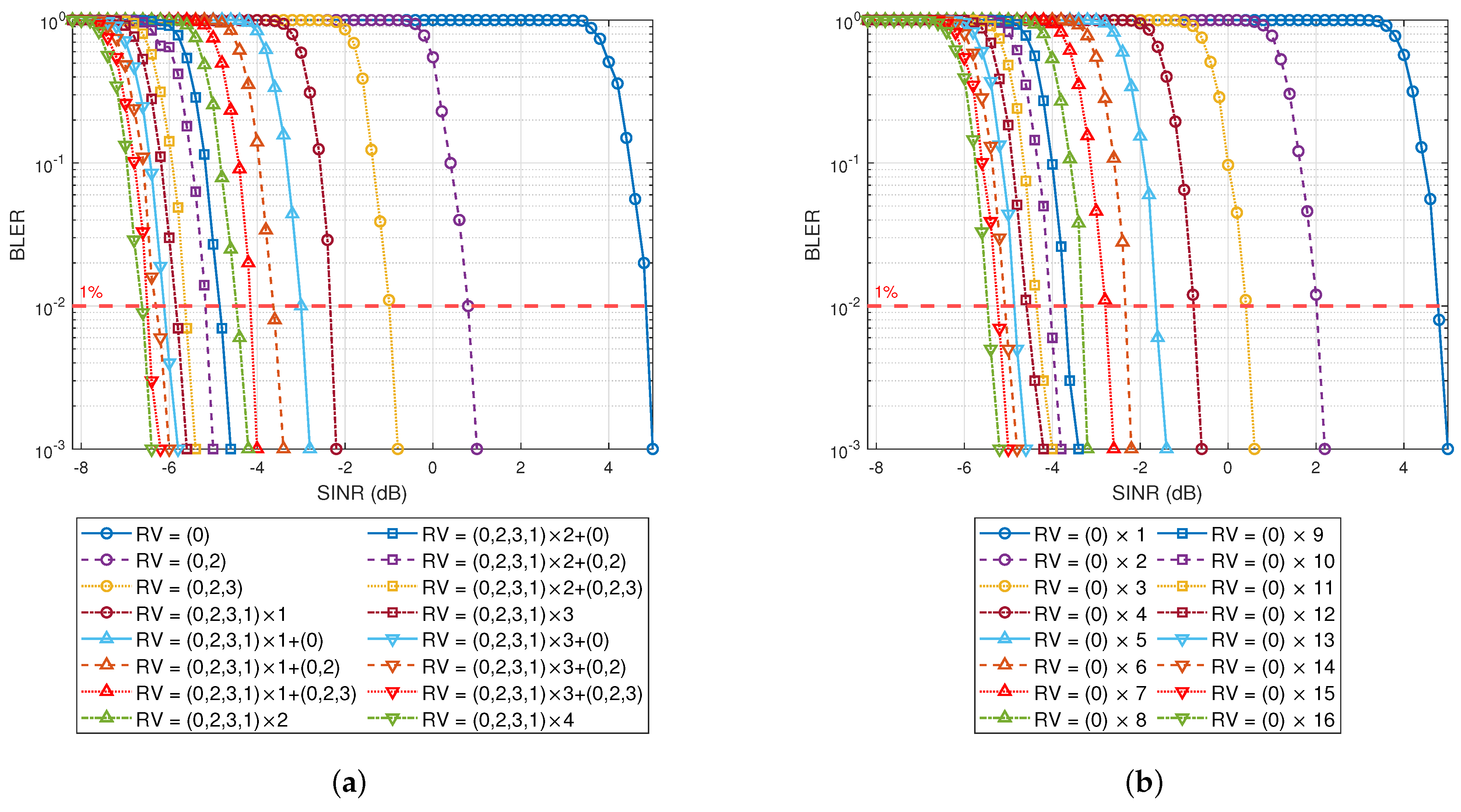
4.2. HARQ Retransmission Performance Analysis

Researchers have analyzed and evaluated the cyclic buffer rate matching and bit selection algorithms for the low-density parity-check code (LDPC) in 5G NR. Moreover, they investigated and compared the performances of HARQ retransmissions of different RV sequences. The results indicate that the sequential performances for RV = ( 0 , 2 , 3 , 1 ) are optimal [45]. Building upon this foundation, this paper simulates the SINR gain obtained after each retransmission, which is convenient for the subsequent research.
When using different RVs for each retransmission (sending data in the order of 0 , 2 , 3 , 1 ), the block error rate (BLER) curves of the UE data are shown in Figure 9a. In the figure’s legend, RV = ( 0 , 2 , 3 , 1 ) × n + ( x ) means that the data have been transmitted ( 4 n + number of x ) times. For example, an RV = ( 0 , 2 , 3 , 1 ) × 2 + ( 0 , 2 ) signifies that the data have been transmitted ( 4 × 2 + 2 ) = 10 times, which includes three instances of RV = 0 , three instances of RV = 2 , two instances of RV = 3 , and two instances of RV = 1 . The gain obtained from each retransmission is quantified and listed in Table 2. When using the same RV for each retransmission (RV = 0 ), the BLER curve of the UE data is shown in Figure 9b, and the gains from each retransmission are presented in Table 3.
It can be observed from Figure 9a that the numerical gain for the second transmission (RV = 2 ) is 1.5119 γ (accounting for 151.19% of the first transmission) when using 1% BLER as the baseline. Similarly, the numerical gain for the third transmission (RV = 3 ) is 1.3100 γ (with 131.00% of the first transmission). And for the fourth transmission (RV = 1 ), it is 1.3861 γ (with 138.61% of the first transmission). In addition, the gain of the CC-HARQ transmission method in the simulation is not as high as that of IR-HARQ. Therefore, gains of 100%, 151.19%, 131.00%, and 138.61% are used for each retransmission in the following simulation.

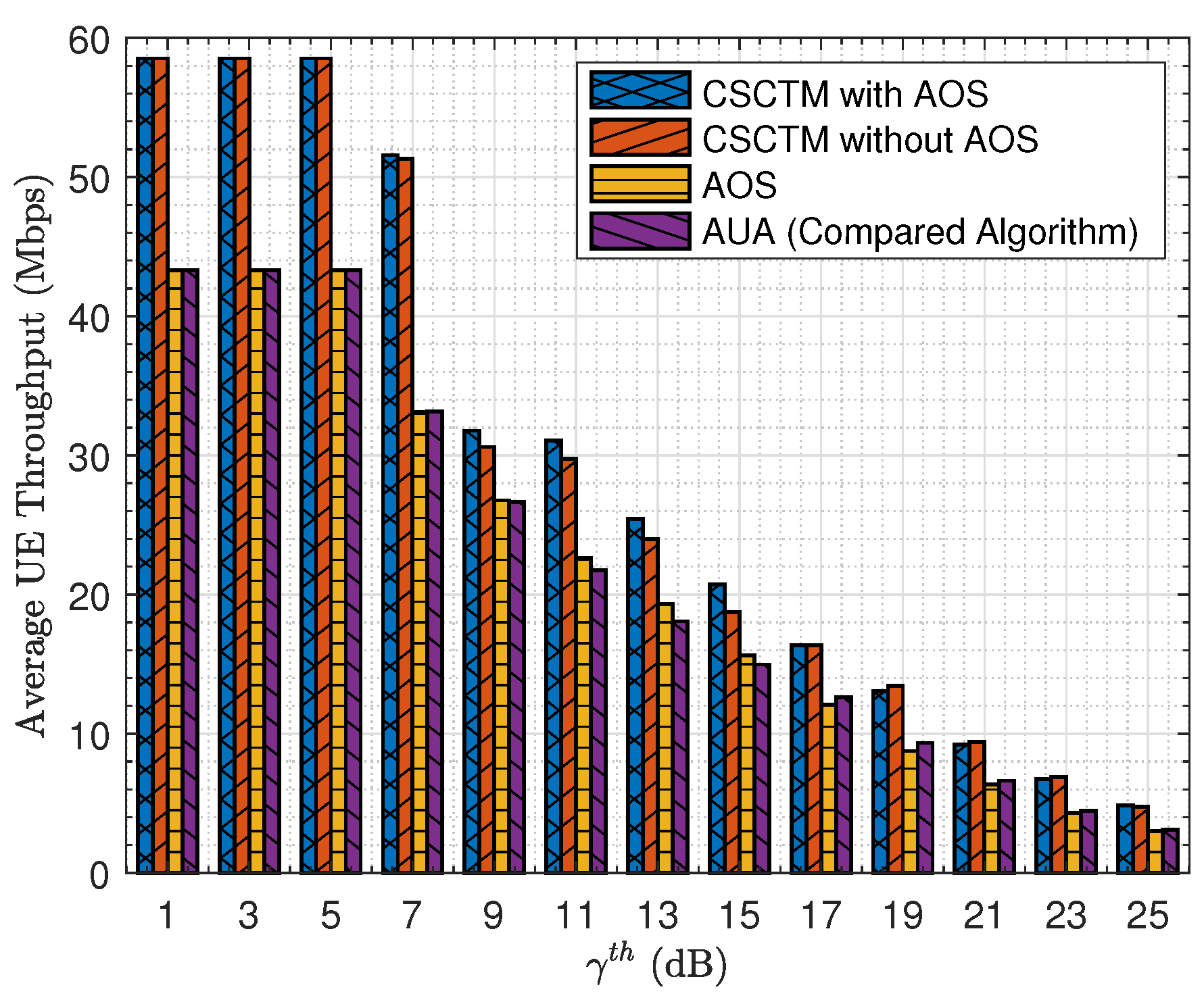
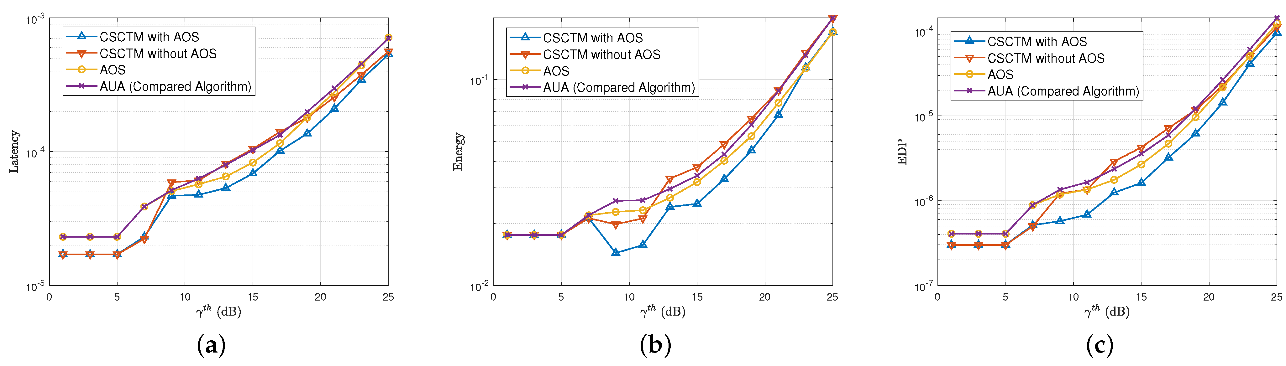
4.3. The Performance Comparison between CSCTM and AOS

With the advancement of modern communication technology, there has been an increase in frequency, resulting in a reduction in transmission distance. In this paper, a specific distance is deliberately chosen to pose challenges for successful decoding in a single transmission and to demonstrate the advantages of CNs in HRLLC. In addition, considering the trade-off between minimizing latency and energy, the minimum power for a single transmission is specifically utilized, which is 5 dBm (3.2 mW). Unless specified otherwise, the relevant parameters of the simulation are shown in Table 4.
In this paper, we use adaptive UE aggregation (AUA) as the object of comparison to demonstrate the superiority of our proposed algorithm [12]. AUA is a dynamically adjusted transmission algorithm that allows UE with different channel qualities to use different transmission modes at different SINR thresholds. Through the relevant simulations, Figure 10 shows the average UE throughput under different SINR thresholds. By determining the UE transmission strategy and flexibly controlling the transmission of UE and CN, CSCTM can effectively stop the energy consumption of UE or CN that is ineffective. At the same time, CSCTM can combine bit-level processing with symbol-level processing, which effectively reduces resource overhead during bit-level processing. In addition, CNs are connected through PSSCH for data concatenation, and suitable, RV is determined for transmission through CSCTM technology. During retransmission, additional parity bits are carried out to reduce the error rate of retransmission. Therefore, CSCTM with AOS has shown excellent performance in throughput, which is significantly higher than AUA and only AOS algorithms, indicating a significant reduction in transmission latency.
Furthermore, Figure 11 illustrates the latency, energy consumption, and EDP of different algorithms under various threshold levels γ th , respectively. The latency figure statistically analyzes the average time required for all UE data to be transmitted to the gNB at different γ th settings. In Figure 11a, it can be observed that the CSCTM maintains lower latency at both higher and lower γ th . Although performance in the middle range is not ideal, the AOS algorithm can make adjustments by controlling the assisted UE, creating a complementary effect. Ultimately, the entire system demonstrates good latency performance across different γ th settings under the joint support of CSCTM and AOS.
In addition, there are latency and energy consumption considerations when data are transmitted between two devices. There might be a sudden decrease in energy consumption when the γ th = 9 dB because the transmission number from CN to gNB may increase, as shown in Figure 11b. Moreover, the AOS algorithm prioritizes the decoded UE to maximize resource utilization with CN assistance, which provides assistance resources to more needed UE when γ th is larger than 9 dB. Due to φ being a fixed value at different SINR thresholds, the AOS algorithm has an advantage for models with higher transmission times (high γ th ). It is not suitable to use the AOS algorithm at a low SINR threshold. However, CSCTM can offset the disadvantage of AOS at low SINR thresholds, which means that CSCTM and AOS algorithms can be combined for future asymmetric IoE scenarios. The application of such algorithms enables data transmission to devices beyond traditional ranges while maintaining lower overall latency and energy consumption. Even in scenarios with high device densities, CSCTM and AOS algorithms remain capable of handling the pressure, ensuring stability and reliability in system operations. Consequently, data transmission is no longer restricted by geographical limitations. As a result, the proposed algorithm in Figure 11c shows a 25–65% reduction in EDP compared to the AUA algorithm at different SINR thresholds.

5. Conclusions

This paper introduces a novel approach for UE aggregation in future asymmetric IoE scenarios, termed channel-sensing-based multipath multihop cooperative transmission with HARQ. The method, called CSCTM, involves the transmission strategy for UE, the decision of transmission RVs for UE and CNs, joint transmission involving symbol-level and bit-level processing, and the prioritizing algorithm AOS to address capacity constraints for CNs. Moreover, the concept of multipath cooperative transmission utilizes multihop technology, which makes data transmission more flexible. Result analysis demonstrates that CSCTM achieves the most efficient transmission, optimally enhancing UE experience, boosting device coverage and transmission reliability, and reducing EDP by 25–65% compared to the AUA algorithm at different SINR thresholds.
This research provides valuable insights into the potential of distributed cooperation systems for future asymmetric IoE networks. In future work, the impact of potential security issues will be considered, which will represent a higher-level challenge, as well as the power control of multiple UE and CNs.

Author Contributions

Conceptualization, H.-M.C. and R.F.; data curation, H.-M.C., R.F. and Z.W.; formal analysis, H.-M.C., R.F., S.W. and Y.S.; investigation, H.-M.C., R.F. and Y.Z.; methodology, H.-M.C., R.F. and S.W.; project administration, H.-M.C. and R.F.; resources, H.-M.C. and R.F.; software, H.-M.C., R.F. and Z.W.; supervision, H.-M.C., R.F., S.W., Z.W., Y.S. and Y.Z.; validation, H.-M.C., R.F., Y.S. and Y.Z.; visualization, H.-M.C. and R.F.; writing—original draft, H.-M.C. and R.F.; writing—review and editing, H.-M.C. and R.F. All authors have read and agreed to the published version of the manuscript.

Funding

This work was supported by BJUT Project no. 40042001202218 and the National Key Research and Development Program of China (No. 2020YFF0305401).

Data Availability Statement

The original contributions presented in this study are included in the article’s further inquiries can be directed to the corresponding authors.

Conflicts of Interest

Author Shoufeng Wang was employed by the company AsiaInfo Technologies (China) Inc. The remaining authors declare that the research was conducted in the absence of any commercial or financial relationships that could be construed as a potential conflict of interest.

Abbreviations

The following abbreviations are used in this manuscript:
3GPPthird-generation partnership project
5G NRfifth-generation new radio
6Gsixth-generation
ACKacknowledgment
AOSascending offset sort
ARQautomatic repeat request
ASabsolute sort
AUAadaptive UE aggregation
BLERblock error rate
CC-HARQchase combining hybrid automatic repeat request
CNcooperative node
CPcyclic prefix
CRCcyclic redundancy check
CSCTMchannel-sensing-based cooperative transmission mechanism
CSIchannel state information
C-SWaPCost, size, weight, and power
DCIdownlink control information
DTLdirect transmission link
EDPenergy-delay product
gNBnext-generation node base station
HARQhybrid automatic repeat request
HTLhybrid transmission link
IIoTIndustrial Internet of Things
IoEInternet of Everything
IR-HARQincremental redundancy hybrid automatic repeat request
ITLindirect transmission link
LDPClow-density parity-check code
LTElong-term evolution
MCSmodulation and coding scheme
MIMOmultiple-input multiple-output
MPTCPmultipath transmission control protocol
UAVunmanned aerial vehicle
UEuser equipment
ProSeproximity service
PDCCHphysical downlink control channel
PSSCHphysical sidelink control channel
PUSCHphysical uplink shared channel
RAresource allocation
RVredundancy version
SINRsignal-to-interference-plus-noise ratio

References

  1. Rong, B. 6G: The Next Horizon: From Connected People and Things to Connected Intelligence. IEEE Wirel. Commun. 2021, 28, 8. [Google Scholar] [CrossRef]
  2. Ren, Q.; Sun, Y.; Wang, T.; Zhang, B. Energy-Efficient Cooperative MIMO Formation for Underwater MI-Assisted Acoustic Wireless Sensor Networks. Remote Sens. 2022, 14, 3641. [Google Scholar] [CrossRef]
  3. Nguyen, D.C.; Ding, M.; Pathirana, P.N.; Sensviratne, A.; Li, J.; Niyato, D.; Dobre, O.; Poor, H.V. 6G Internet of Things: A Comprehensive Survey. IEEE Internet Things J. 2022, 9, 359–383. [Google Scholar] [CrossRef]
  4. Vivo Mobile Communications Ltd. Study on UE Aggregation for Industry with Multi-Connectivity. In Proceedings of the 3GPP TSG SA WG2 Electronic Meeting, 18–22 October 2021; Available online: https://www.3gpp.org/ftp/tsg_sa/WG2_Arch/TSGS2_146E_Electronic_2021-08/INBOX/DRAFTS/UE%20Aggregation%20for%20Industry%20with%20Multi-connectivity.pdf (accessed on 23 April 2024).
  5. Wang, C.-X.; You, X.; Gao, X.; Zhu, X.; Li, Z.; Zhang, C.; Wang, H.; Huang, Y.; Chen, Y.; Haas, H.; et al. On the Road to 6G: Visions, Requirements, Key Technologies, and Testbeds. IEEE Commun. Surv. Tutor. 2023, 25, 905–974. [Google Scholar] [CrossRef]
  6. China Mobile. Motivation of Study for UE Aggregation. In Proceedings of the 3GPP TSG RAN Rel-18 Workshop, RWS-210355, 28 June 2021–2 July 2021; Available online: https://www.3gpp.org/ftp/TSG_RAN/TSG_RAN/TSGR_AHs/2021_06_RAN_Rel18_WS/Docs/RWS-210355.zip (accessed on 24 April 2024).
  7. Aasen, H.; Honkavaara, E.; Lucieer, A.; Zarco-Tejada, P.J. Quantitative Remote Sensing at Ultra-High Resolution with UAV Spectroscopy: A Review of Sensor Technology, Measurement Procedures, and Data Correction Workflows. Remote Sens. 2018, 10, 1091. [Google Scholar] [CrossRef]
  8. Fantacci, R.; Picano, B. End-to-End Delay Bound for Wireless uVR Services Over 6G Terahertz Communications. IEEE Internet Things J. 2021, 8, 17090–17099. [Google Scholar] [CrossRef]
  9. Ma, S.; Wang, S.; Tsai, W.-T. Delay Analysis of Consensus Communication for Blockchain-Based Applications Using Network Calculus. IEEE Wirel. Commun. Lett. 2022, 9, 1825–1829. [Google Scholar] [CrossRef]
  10. Verma, S.; Kawamoto, Y.; Fadlullah, Z.M.; Nishiyama, H.; Kato, N. A Survey on Network Methodologies for Real-Time Analytics of Massive IoT Data and Open Research Issues. IEEE Commun. Surv. Tutor. 2017, 19, 1457–1477. [Google Scholar] [CrossRef]
  11. Lyu, L.; Chen, C.; Zhu, S.; Cheng, N.; Yang, B.; Guan, X. Control Performance Aware Cooperative Transmission in Multiloop Wireless Control Systems for Industrial IoT Applications. IEEE Internet Things J. 2018, 5, 3954–3966. [Google Scholar] [CrossRef]
  12. Chen, H.; Fang, R.; Chen, T.; Wang, P.; Wang, Z.; Lin, S.; Li, F. A Novel Adaptive UE Aggregation-Based Transmission Scheme Design for a Hybrid Network with Multi-Connectivity. Symmetry 2023, 5, 1766. [Google Scholar] [CrossRef]
  13. Renzo, M.D.; Zappone, A.; Debbah, M.; Alouini, M.-S.; Yuen, C.; Rosny, J.; Tretyakov, S. Smart Radio Environments Empowered by Reconfigurable Intelligent Surfaces: How It Works, State of Research, and The Road Ahead. IEEE J. Sel. Areas Commun. 2020, 38, 2450–2525. [Google Scholar] [CrossRef]
  14. Liu, Y.; Liu, X.; Mu, X.; Hou, T.; Xu, J.; Renzo, M.D.; AI-Dhahir, N. Reconfigurable Intelligent Surfaces: Principles and Opportunities. IEEE Commun. Surv. Tutor. 2021, 23, 1546–1577. [Google Scholar] [CrossRef]
  15. Boulogeorgos, A.-A.A.; Alexiou, A. Performance Analysis of Reconfigurable Intelligent Surface-Assisted Wireless Systems and Comparison With Relaying. IEEE Access 2020, 8, 94463–94483. [Google Scholar] [CrossRef]
  16. More, S.; Naik, U.L. Optimization driven Multipath Routing for the video transmission in the VANET. In Proceedings of the 2018 IEEE Global Conference on Wireless Computing and Networking (GCWCN), Lonavala, India, 23–24 November 2018; pp. 6–10. [Google Scholar]
  17. Sadi, Y.; Erkucuk, S.; Panayirci, E. Flexible Physical Layer based Resource Allocation for Machine Type Communications Towards 6G. In Proceedings of the 2020 2nd 6G Wireless Summit (6G SUMMIT), Levi, Finland, 17–20 March 2020; pp. 1–5. [Google Scholar]
  18. Hu, J.; Liu, G.; Ma, Z.; Xiao, M.; Fan, P. Low-Complexity Resource Allocation for Uplink RSMA in Future 6G Wireless Networks. IEEE Wirel. Commun. Lett. 2024, 13, 565–569. [Google Scholar] [CrossRef]
  19. Mahmood, N.H.; López, O.A.; Alves, H.; Latva-Aho, M.; Fan, P. A Predictive Interference Management Algorithm for URLLC in Beyond 5G Networks. IEEE Commun. Lett. 2021, 25, 995–999. [Google Scholar] [CrossRef]
  20. Suyama, S.; Okuyama, T.; Nonaka, N.; Asai, T. Recent Studies on Massive MIMO Technologies for 5G Evolution and 6G. In Proceedings of the 2022 IEEE Radio and Wireless Symposium (RWS), Las Vegas, NV, USA, 16–19 January 2022; pp. 90–93. [Google Scholar]
  21. Romero-Peña, J.S.; Cardona, N. Diffuse Modular Honeycomb Passive Reflector for Efficient mmWave Propagation in Indoor Environments. In Proceedings of the 2022 Joint European Conference on Networks and Communications & 6G Summit (EuCNC/6G Summit), Grenoble, France, 7–10 June 2022; pp. 49–52. [Google Scholar]
  22. Chirivella-Perez, E.; Salva-Garcia, P.; Ricart-Sanchez, R.; Calero, J.A.; Wang, Q. Intent-Based E2E Network Slice Management for Industry 4.0. In Proceedings of the 2021 Joint European Conference on Networks and Communications & 6G Summit (EuCNC/6G Summit), Porto, Portugal, 8–11 June 2021; pp. 353–358. [Google Scholar]
  23. Makki, B.; Svensson, T.; Zorzi, M. Finite Block-Length Analysis of the Incremental Redundancy HARQ. IEEE Wirel. Commun. Lett. 2014, 3, 529–532. [Google Scholar] [CrossRef]
  24. Anand, A.; de-Veciana, G. Resource Allocation and HARQ Optimization for URLLC Traffic in 5G Wireless Networks. IEEE J. Sel. Areas Commun. 2018, 36, 2411–2421. [Google Scholar] [CrossRef]
  25. Khan, F.; Rehma, A.; Zhang, Y.; Mastorrakis, S.; Song, H.; Jan, M.A.; Dev, K. A Secured and Reliable Continuous Transmission Scheme in Cognitive HARQ-Aided Internet of Things. IEEE Internet Things J. 2021, 8, 14835–14844. [Google Scholar] [CrossRef]
  26. Dosti, E.; Shehab, M.; Alves, H.; Latva-aho, M. Ultra reliable communication via CC-HARQ in finite block-length. In Proceedings of the 2017 European Conference on Networks and Communications (EuCNC), Oulu, Finland, 12–15 June 2017; pp. 1–5. [Google Scholar]
  27. Zhao, M.-M.; Zhang, G.; Xu, C.; Zhang, H.; Li, R.; Wang, J. An Adaptive IR-HARQ Scheme for Polar Codes by Polarizing Matrix Extension. IEEE Commun. Lett. 2018, 22, 1306–1309. [Google Scholar] [CrossRef]
  28. Frenger, P.; Parkvall, S.; Dahlman, E. Performance comparison of HARQ with Chase combining and incremental redundancy for HSDPA. In Proceedings of the IEEE 54th Vehicular Technology Conference (VTC), Atlantic City, NJ, USA, 7–11 October 2001; pp. 1829–1833. [Google Scholar]
  29. Cheng, J.-F. Coding performance of hybrid ARQ schemes. IEEE Trans. Commun. 2006, 54, 1017–1029. [Google Scholar] [CrossRef]
  30. Avranas, A.; Kountouris, M.; Ciblat, P. Energy-Latency Tradeoff in Ultra-Reliable Low-Latency Communication With Retransmissions. IEEE J. Sel. Areas Commun. 2018, 36, 2475–2485. [Google Scholar] [CrossRef]
  31. Kim, D.; Jung, B.C.; Lee, H.; Sung, D.K.; Yoon, H. Optimal modulation and coding scheme selection in cellular networks with hybrid-ARQ error control. IEEE Trans. Wirel. Commun. 2008, 7, 5195–5201. [Google Scholar] [CrossRef]
  32. Nasraoui, L.; Ikki, S. Neighbor Discovery for ProSe and V2X Communications. IEEE Internet Things J. 2021, 8, 7241–7251. [Google Scholar] [CrossRef]
  33. Ganesan, K.; Mallick, P.B.; Löhr, J. NR Sidelink Enhancement in 3GPP Release 17. J. ICT Stand. 2021, 9, 79–90. [Google Scholar] [CrossRef]
  34. Ganesan, K. 5G Advanced: Sidelink Evolution. IEEE Commun. Stand. Mag. 2023, 7, 58–63. [Google Scholar] [CrossRef]
  35. Harounabadi, M.; Soleymani, D.M.; Bhadauria, S.; Leyh, M.; Roth-Mandutz, E. V2X in 3GPP Standardization: NR Sidelink in Release-16 and Beyond. IEEE Commun. Stand. Mag. 2021, 5, 12–21. [Google Scholar] [CrossRef]
  36. Bazzi, A.; Campolo, C.; Todisco, V.; Bartoletti, S.; Decarli, N.; Molinaro, A.; Berthet, A.O.; Gallacher, R.A. Toward 6G Vehicle-to-Everything Sidelink: Nonorthogonal Multiple Access in the Autonomous Mode. IEEE Veh. Technol. Mag. 2023, 18, 50–59. [Google Scholar] [CrossRef]
  37. Verma, S.; Kawamoto, Y.; Kato, N. A Network-Aware Internet-Wide Scan for Security Maximization of IPv6-Enabled WLAN IoT Devices. IEEE Internet Things J. 2021, 8, 8411–8422. [Google Scholar] [CrossRef]
  38. Chen, H.-M.; Wang, J.-B.; Chen, M. Downlink outage probability of distributed antenna systems over shadowed Nakagami-m fading channels with antenna selection. In Proceedings of the 2009 International Conference on Wireless Communications & Signal Processing, Nanjing, China, 13–15 November 2009; pp. 1–4. [Google Scholar]
  39. Laros III, J.H.; Pedretti, K.; Kelly, S.M.; Shu, W.; Ferreira, K.; Dyke, J.V.; Vaughan, C. Energy-Efficient High Performance Computing; Springer: London, UK, 2012; pp. 51–55. [Google Scholar] [CrossRef]
  40. Vijaykumar, G.; Pekhimenko, A.; Jog, S.; Ghose, A.; Bhowmick, R.; Ausavarungnirun, C.; Das, M.; Kandemir, T.C.; Mowry, O.M. A Framework for Accelerating Bottlenecks in GPU Execution with Assist Warps; Elsevier: Amsterdam, The Netherlands, 2017; pp. 373–415. [Google Scholar] [CrossRef]
  41. Ivan, R.; Nikola, B.; Osman, S.; Adrian, C.; Veljko, M. An Overview of Architecture-Level Power- and Energy-Efficient Design Techniques; Elsevier: Amsterdam, The Netherlands, 2015; pp. 1–57. [Google Scholar]
  42. dos Santos, A.; Soares, B.; Fan, C.; Kuipers, M.; Sabino, S.; Grilo, A.M.; Pereira, P.R.B.; Nunes, M.S.; Casaca, A. Characterization of Substation Process Bus Network Delays. IEEE Trans. Ind. Inform. 2018, 14, 2085–2094. [Google Scholar] [CrossRef]
  43. Hamidi-Sepehr, F.; Nimbalker, A.; Ermolaev, G. Analysis of 5G LDPC Codes Rate-Matching Design. In Proceedings of the 2018 IEEE 87th Vehicular Technology Conference (VTC Spring), Porto, Portugal, 3–6 June 2018; pp. 1–5. [Google Scholar]
  44. Gradshteyn, I.S.; Ryzhik, I.M. Table of Integrals, Series, and Products, 7th ed.; Jeffrey, A., Zwillinger, D., Eds.; Elsevier: Burlington, VT, USA; Academic Press: Burlington, VT, USA, 2007. [Google Scholar]
  45. Lagrange, X. Throughput of HARQ protocols on a block fading channel. IEEE Commun. Lett. 2010, 14, 257–259. [Google Scholar] [CrossRef]
Figure 1. The scene featuring different cooperative transmission strategies.
Symmetry 16 01225 g001
Figure 3. The newly designed control signals of unicast and groupcast.
Symmetry 16 01225 g003
Figure 4. The flowchart of 6G baseband signal processing at the receiver side.
Symmetry 16 01225 g004
Figure 5. The flowchart of the AOS algorithm.
Symmetry 16 01225 g005
Figure 6. The divided stages of the average transmission number and the probability under different transmission links.
Symmetry 16 01225 g006
Figure 7. The flowchart of CSCTM.
Symmetry 16 01225 g007
Figure 8. The UE average throughput (blue bars) and throughput gain (purple triangles) under AOS with different factor values φ .
Symmetry 16 01225 g008
Figure 9. BLER of repeated transmissions by (a) different RV (IR-HARQ) and (b) identical RV (CC-HARQ).
Symmetry 16 01225 g009
Figure 10. The average UE throughput under different SINR thresholds.
Symmetry 16 01225 g010
Figure 11. The (a) latency, (b) energy consumption, and (c) EDP under different SINR thresholds.
Symmetry 16 01225 g011
Table 1. Notation and operation descriptions.
NotationExplanation
RThe radius of the entire cell
rDistance between CN and gNB
N U The total UE number within the cell
N C The total CN number within the cell
N t , i The transmission number of the ith UE when gNB decodes successfully
γ th SINR threshold
γ i , k UB SINR between the ith UE and gNB during the kth transmission
γ i , j , k UC SINR between the ith UE and jth CN during the kth transmission
γ j , k CB SINR between the jth CN and gNB during the kth transmission
α i , j , k Whether or not the jth CN needs to assist the ith UE during the kth transmission
β i , k Whether or not the ith UE needs to transmit data during the kth transmission
T all , i The overall latency of ith UE data successfully decoded at gNB
E all , i The overall energy consumption of ith UE data successfully decoded at gNB
A C The maximum number of UE that can be assisted by a single CN in one time segment
A S i , j , k The absolute sort of ith UE and jth CN during the kth transmission
T trans The transmission latency for one time segment
T prop The propagation latency for one time segment
T queue The queuing latency for one time segment
T proc The processing latency for one time segment
P L Pathloss of the channel
P s Packet size
P t Transmission power
R Link rate
T ¯ M The average transmission number under assistance from M CNs
qThe probability of transmission failure
q UB The probability of transmission failure from UE to gNB
q i CB The probability of transmission failure from ith CN to gNB
q j UC The probability of transmission failure from UE to jth CN
Q s The processing latency at the symbol level
Q b The processing latency at the bit level
φ A dynamically adjusted SINR factor
κ The number of times that the UE waits for the CN to transmit other UE data in the queue
fThe successful transmission flag
MThe number of CNs assisting UE in transmission
nThe transmission number of specific tasks
η 1 , η 2 The main factor values used in transmission strategy determination
Ω Shadowing effect, modeled by a log-normal distribution
IThe interference within devices
gThe fast channel fading, following a Nakagami distribution
σ 2 The noise of the system, modeled as a Gaussian random noise with zero mean and variance
N * The set of positive integers
· The absolute operation to the input parameter
Table 2. Retransmissions by different RVs.
Tx
Number
Previous RVCurrent RVSINR
Value
SINR Value
Increment
SINR dB
Increment
1st TxRV = (-)RV = (0) γ γ   ( 100.00 % )
2nd TxRV = (0)RV = (0, 2) 2.5119 γ 1.5119 γ   ( 151.19 % ) 4 dB
3rd TxRV = (0, 2)RV = (0, 2, 3) 3.8019 γ 1.3100 γ   ( 131.00 % ) 1.8 dB
4th TxRV = (0, 2, 3)RV = (0, 2, 3, 1) × 1 5.1880 γ 1.3861 γ   ( 138.61 % ) 1.35 dB
5th TxRV = (0, 2, 3, 1) × 1RV = (0, 2, 3, 1) × 1 + (0) 6.0255 γ 0.8375 γ   ( 83.75 % ) 0.65 dB
6th TxRV = (0, 2, 3, 1) × 1 + (0)RV = (0, 2, 3, 1) × 1 + (0, 2) 6.7608 γ 0.7353 γ   ( 73.53 % ) 0.5 dB
7th TxRV = (0, 2, 3, 1) × 1 + (0, 2)RV = (0, 2, 3, 1) × 1 + (0, 2, 3) 7.5856 γ 0.8248 γ   ( 82.48 % ) 0.5 dB
8th TxRV = (0, 2, 3, 1) × 1 + (0, 2, 3)RV = (0, 2, 3, 1) × 2 8.1280 γ 0.5424 γ   ( 54.24 % ) 0.3 dB
Table 3. Retransmissions by identical RVs.
Tx
Number
Previous RVCurrent RVSINR
Value
SINR Value IncrementSINR dB
Increment
1st TxRV = (-)RV = (0) × 1 γ γ   ( 100.00 % )
2nd TxRV = (0) × 1RV = (0) × 2 1.8408 γ 0.8408 γ   ( 84.08 % ) 2.65 dB
3rd TxRV = (0) × 2RV = (0) × 3 2.1878 γ 0.3470 γ   ( 34.70 % ) 0.75 dB
4th TxRV = (0) × 3RV = (0) × 4 2.4832 γ 0.2954 γ   ( 29.54 % ) 0.55 dB
5th TxRV = (0) × 4RV = (0) × 5 2.6305 γ 0.1473 γ   ( 14.73 % ) 0.25 dB
6th TxRV = (0) × 5RV = (0) × 6 2.7544 γ 0.1239 γ   ( 12.39 % ) 0.2 dB
7th TxRV = (0) × 6RV = (0) × 7 2.8511 γ 0.0967 γ   ( 9.67 % ) 0.15 dB
8th TxRV = (0) × 7RV = (0) × 8 2.9512 γ 0.1001 γ   ( 10.01 % ) 0.15 dB
Table 4. Simulation settings.
ParameterValue
Cell radius (R) 1000 m
Distance between cooperation node and gNB (r) 500 m
UE number ( N U )10,000
Cooperation node number ( N C )32
The maximum assisting number for a single CN ( A C )16
Transmit power ( P t ) 3.2 mW
Packet size ( P s ) 1000 bits
Link rate ( R ) 10 8 bps
Adjusted SINR factor ( φ ) 12.0 dB
Disclaimer/Publisher’s Note: The statements, opinions and data contained in all publications are solely those of the individual author(s) and contributor(s) and not of MDPI and/or the editor(s). MDPI and/or the editor(s) disclaim responsibility for any injury to people or property resulting from any ideas, methods, instructions or products referred to in the content.

